Embed Size (px)
Citation preview
Towards a Dynamic Framework for Interactivity
Charlie Roberts
Submitted in partial fulfillment of the requirements for a Master of Arts degreeMedia Arts and Technology Program
University of California, Santa Barbara

Acknowledgments
My committee: JoAnn Kuchera-Morin, Matthew Wright, Tobias Hollerer and Curtis Roads
The AlloSphere working group, in particular Lance Putnam and Graham Wakefield
The MAT community
Towards a Dynamic Framework for Interactivity Charlie Roberts
1
Table Of Contents
Abstract 5
1. Introduction 5
1.1 Problem Statement 5
1.2 Project Goal 6
1.3 Definition of Terms 6
1.4 Document Overview 8
2. Background Research 8
2.1 Interactive Frameworks Integrated Into Virtual Reality Toolkits 8
2.2 Standalone Interactive Frameworks 9
3. The Device Server in Detail 11
3.1 An Overview of the Device Server 11
3.2 The Device Server Graphical User Interface (GUI) 13
3.3 Lua Configuration Files 15
3.3.1 Master Device List 15
3.3.2 Device Configuration Files 15
3.3.3 Application Interface and Implementation Files 17
3.4 OSC Communication 19
3.4.1 Connecting and Disconnecting 19
3.4.2 Sending Messages 20
3.4.3 Dynamically registering to receive control messages 20
3.4.4 Device Communication 21
3.5 Homogenizing Device Signals and Encouraging Experimentation 22
3.6 The Lua Expression Engine 23
3.7 Software Architecture 24
3.8 Signal Flow 26
Towards a Dynamic Framework for Interactivity Charlie Roberts
2
3.9.1 Device Server Plug-ins and the Bundle Manager 29
4. Early Implementations & Lessons Learned 30
4.1 Version 1.0 32
4.2 Device Server Version 2.0 35
4.2.1 The Mapping Layer 35
4.2.2 Expression Engine 36
4.2.3 Application Centric View vs. Device Centric View 37
4.3 Lessons Learned (Device Server 3.0) 37
4.3.1 Moving from XML / JavaScript to Lua 38
4.3.1.1 Code Reuse and Dynamism 38
4.3.1.2 Speed and Efficiency 40
4.3.2 Abstracting the Abstraction Layer 41
4.3.3 Device Driver Plugins 41
5. Comparison and Evaluation 42
5.2.1 VRPN 42
5.2.1.1 Dynamism 42
5.2.1.2 OSC 43
5.2.1.3 Device Agnosticism 43
5.2.1.4 Distributed Servers, Latency and GUIs 44
5.2.1.5 Control Signal Processing 45
5.2.2 Gadgeteer 45
5.2.3 VRui 46
5.2.4 DIVERSE ToolKit (DTK) 46
5.2.5 Mapping tools of the Digital Orchestra Toolbox 47
5.3 Latency 48
5.4 User Feedback 48
6. Future Directions and Conclusion 49
Towards a Dynamic Framework for Interactivity Charlie Roberts
3
Appendix 1 - Sample Lua Configuration Files and Scripts 53
Appendix 2 - Device Server Lua Scripting Reference 57
General Usage 57
Console Object 57
Mapping Object 57
Application Object 58
Constants 59
References 60
Towards a Dynamic Framework for Interactivity Charlie Roberts
4
Abstract
The Device Server provides both a methodology and an application for distributing control signals to
software applications. The interface of the Device Server lets users see connections between devices and
application functionalities, alter these connections and save alterations into configuration files for later
use. The methodology abstracts knowledge of devices away from applications allowing developers to
think of control signals in terms of functional usage rather than hardware specific constraints. The Device
Server uses the Lua programming language for configuration and control signal processing; this provides
a level of dynamism absent in other interactive frameworks. I wrote the Device Server with the goal of
easing multi-user interaction inside the AlloSphere immersive instrument at the University of California,
Santa Barbara.
1. Introduction
The realtime rendering of complex sonifications and visualizations often require a distributed computing
architecture to be successfully realized. In large scale immersive environments such as the AlloSphere 1
the processing requirements of projects are amplified by the size of the physical space; more speakers
and more projectors are required along with more processing power to drive them. Similarly, the
infrastructure for dealing with interactivity in large spaces poses problems that are often absent in small
interactive systems. How can multiple users interact with a visualization simultaneously? How can one
device speak to multiple applications? How can an application use a variety of devices to control the
same functionality? How can we free application developers from having to manage a myriad of device
drivers and control signal processing scripts? How can we let users decide how to interact with data
instead of having developers decide for them?
1.1 Problem Statement
This project focuses on the problem of providing a scalable, dynamic framework for interactivity. Existing
interactive frameworks for virtual reality are inflexible and static; applications utilizing these frameworks
must be recompiled whenever they want to change the configuration of devices controlling them.
Towards a Dynamic Framework for Interactivity Charlie Roberts
5
Although this is arguably acceptable for virtual reality experiments where controls are well defined in
advance, it does not allow fluid experimentation with devices in multi-user systems. The problem is further
aggravated by a lack of graphical user interfaces in the server applications of existing frameworks. This
lack prevents users and developers from seeing how devices are connected to application parameters
and from changing these connections without having to modify or recompile application source code.
Creating usable control systems for navigating and manipulating Virtual Reality Environments (VREs) is
challenging, especially when there are multiple users engaged in different tasks simultaneously. Defining
control systems for musical and artistic performance systems is equally difficult; each artist will want to
customize their controls to ensure as much expressive potential as possible. Interactive frameworks need
to provide flexibility and dynamism that encourages experimentation and innovation with devices and
control; instead, current frameworks serve as a stumbling block to these goals.
1.2 Project Goal
The Device Server was conceptualized as part of a framework to provide scalable, dynamic, multi-user
interaction in the AlloSphere. The initial design allows multiple users to interact with multiple applications
via multiple devices while avoiding the introduction of latency. It is intended to free application developers
from incorporating device specific drivers into their applications and enforce the decoupling of specific
devices from specific application functionalities. It should scale down to single user / single device
systems and scale up to as many users and devices as possible. Finally, it should allow easy
experimentation with interactive devices and let users individually customize their interfaces to
applications.
1.3 Definition of Terms
Device - In this paper the term device will generally refer to a piece of hardware that provides interactive
affordances to users. However, devices feeding into the Device Server can also be virtual; for example, a
Towards a Dynamic Framework for Interactivity Charlie Roberts
6

row of sliders on a computer screen could be seen as a “device” by the Device Server and used to control
applications. Other example devices include gamepads, mobile phones and VR gloves.
Control - Usually one particular interface element of a device. For example, a single button is a control on
a gamepad device. In some cases one interface element might have multiple controls associated with it,
e.g. a joystick might generate both a X and a Y signal separately.
Signal - Any time-varying or spatial-varying quantity that a control on a device sends to the Device Server
for distribution. I will not make any distinction between discrete and continuous time signals, nor discrete
continuous valued signals; all signals are created equal for purposes of this paper.
Message - The Device Server outputs messages to client applications. The messages are formatted
according to The Open Sound Control protocol (OSC), which will be discussed later.
Application - An application is a computer program that is a client to the Device Server; it registers to
receive messages created from the signals of devices.
Functionality - A functionality is one dimension of control inside a client application. For example,
changing the X position of a camera is one functionality an application might expose; changing the Y
position could be another.
Interface - Each application has a single Lua2 interface file that defines what functionalities the
application exposes and the range of values these functionalities expect to utilize.
Implementation - A Lua file that gives mappings (see below) for a particular interface. There can be
many different implementations for a single interface; users can select which implementation script they
would like to use through the Device Server GUI.
Towards a Dynamic Framework for Interactivity Charlie Roberts
7

Mapping - A mapping takes an application functionality described in the applicationʼs interface file and
routes a signal from a control to that functionality. It may also contain processing scripts that transform the
signal.
1.4 Document Overview
I will begin Section 2 by looking at existing interactivity frameworks, three of which were designed for
Virtual Reality applications, one of which was designed for musical applications. Section 3 will provide a
detailed functional and architectural description of the current Device Server. Section 4 will discuss
previous iterations of the Device Server and the design decisions that brought it to its current state.
Section 5 focuses on usage, evaluation and comparison to existing interactive frameworks. Section 6
discusses further directions for development and concludes.
2. Background Research
2.1 Interactive Frameworks Integrated Into Virtual Reality Toolkits
Many early Virtual Reality (VR) toolkits incorporated interactive functionality intended to free application
developers from worrying about device drivers (references... panda, diver , etc.). However, in most cases
the functionality provided was not designed to be scalable, extensible or abstracted to easily
accommodate different device configurations. As stated on the homepage of the Vrui 3 VR toolkit from UC
Davis “Although all toolkits have some kind of built-in input device driver to hide hardware details, none
provide a higher-level semantic interface that allows to write an application once, and run it in VR
environments with widely differing input environments.” 4 Gadgeteer5, part of the VR Juggler6 package, is
a notable exception to this rule along with the Vrui VR toolkit itself.
Gadgeteer inserts a level of abstraction between device drivers and applications; this layer attempts to
classify devices into one of eight categories: Analog, Command, Digital, Glove, Gesture, Position,
Towards a Dynamic Framework for Interactivity Charlie Roberts
8
Simulator and String. The Simulator category is another level of abstraction that allows devices of one
type of category to pose as another, a design paradigm that can also be found in the Virtual Reality
Peripheral Network (VRPN) 7 which will be discussed shortly. The advantage of abstracting devices into
categories is that any two devices of the same category can be used interchangeably. This means VREs
have a better chance of successfully running in physical locations possessing different devices.
The Vrui VR toolkit also has this level of device abstraction; however, it goes one step further by
introducing the concept of tools. Tools provide a set of functionality while leaving the the inner
composition of the functionality hidden. As one example, multiple devices could be combined to create a
navigation tool. Other navigation tools composed of differing devices might exist but any two tools of the
same type are guaranteed to provide the same range of control signals and can be used interchangeably.
Enforcing these abstractions comes with a price: individual controls of one category cannot easily be
exchanged for controls of another category. In the Device Server the signals generated by all controls are
treated equally as floating point numbers and any control signal maybe exchanged for any other. This
difference between the Device Server and other VR frameworks is discussed in detail in Section 5.
2.2 Standalone Interactive Frameworks
The Virtual Reality Peripheral Network (VRPN) is the most commonly used standalone library for
interfacing with high-end virtual reality devices. It presents a distributed client / server model, where a
server can provide a number of device streams and a typical client is a virtual reality application that
registers to receive one or more streams from one or more servers. VRPN also supports the first
abstraction layer found in Vrui VR and Gadgeteer, i.e. users can request to receive messages from a
Tracker object without worrying about which particular model of tracking device they will be accessing.
The developers of VRPN put a great deal of emphasis on ensuring low latency performance; input
messages from devices often reach connected clients in less than a millisecond. The existence of multiple
servers simultaneously allows for a great deal of flexibility in interactive systems architecture. If a VRE
Towards a Dynamic Framework for Interactivity Charlie Roberts
9
contained ten devices each device could be connected to its own dedicated computer with its own
dedicated VRPN server program running or all ten could run on a single machine with a single server
program. Anything in between these two extremes is also possible. By connecting client applications
directly to the computers hosting devices without using an intermediary (as is the case with the Device
Server) VRPN reduces network overhead and creates the lowest latency connection possible.
Disadvantages of decentralization include more network connections to manage and the lack of a central
location for monitoring connections and signals.
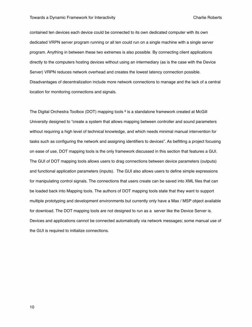
The Digital Orchestra Toolbox (DOT) mapping tools 8 is a standalone framework created at McGill
University designed to “create a system that allows mapping between controller and sound parameters
without requiring a high level of technical knowledge, and which needs minimal manual intervention for
tasks such as configuring the network and assigning identifiers to devices”. As befitting a project focusing
on ease of use, DOT mapping tools is the only framework discussed in this section that features a GUI.
The GUI of DOT mapping tools allows users to drag connections between device parameters (outputs)
and functional application parameters (inputs). The GUI also allows users to define simple expressions
for manipulating control signals. The connections that users create can be saved into XML files that can
be loaded back into Mapping tools. The authors of DOT mapping tools state that they want to support
multiple prototyping and development environments but currently only have a Max / MSP object available
for download. The DOT mapping tools are not designed to run as a server like the Device Server is.
Devices and applications cannot be connected automatically via network messages; some manual use of
the GUI is required to initialize connections.
Towards a Dynamic Framework for Interactivity Charlie Roberts
10

3. The Device Server in Detail
This section will discuss the functional and architectural details of the Device Server.
3.1 An Overview of the Device Server
The Device Server is a router for the signals generated by interactive devices. It aggregates the access of
all devices into a single interface and provides a flexible configuration mechanism allowing client
applications to decide which device signals will be forwarded to them as messages and how those signals
will be transformed. The configuration files are written in Lua; this is also the language used to write
expressions for signal transformation.
Fig.1 The mapping tools GUI. Devices are on the left, application parameters are on the right.
Towards a Dynamic Framework for Interactivity Charlie Roberts
11

Multiple client applications may be connected to the Device Server simultaneously; in the AlloSphere,
typical client applications include data visualizations, scientific simulations and works of visual and sonic
art. Multiple clients can be registered to receive signals from the same controls on the same devices; the
signals can be transformed differently for each application.
Each client application has a single Lua interface file defining the functionalities it exposes for control.
Applications also have implementation files defining which devices and controls are assigned to the
functionalities exposed in the interface. There can be multiple implementations for each application;
different implementation files can be defined to accommodate different numbers of users and different
devices. For example, one implementation for an application might define a configuration for a single user
using a single device while another defines a configuration for multiple devices used by a single user. Yet
another implementation might describe a multiuser setup employing a variety of devices. The application
implementation file in current use can be easily changed in the Device Server GUI; neither the Device
Server nor the application needs to be restarted when an implementation file is selected. This makes it
simple to change configurations when a device is malfunctioning or a user wants to experiment with a
different device.
The Device Server primarily communicates using Open Sound Control (OSC) 9, a network
communications protocol used extensively in the media arts and found in a wide variety of prototyping
platforms. Client applications begin communicating with the Device Server by sending a “handshake”
message using OSC; this message tells the Device Server what the name of the application is, what IP
address the client application is using and what port it would like to receive OSC messages at. When the
handshake is received the Device Server registers the client application and reads in the Lua
configuration files associated with it. The first configuration file, the interface, describes the functionalities
that the application exposes. The second file, the default implementation, describes which controls should
be connected to each functionality and what transformations should be applied to the signals the controls
Towards a Dynamic Framework for Interactivity Charlie Roberts
12
generate. Once the Device Server reads these files it begins serving OSC messages to the client
application as described in the configuration files.
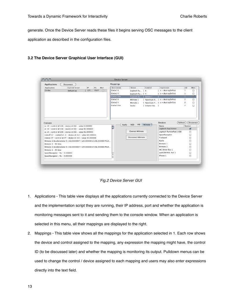
3.2 The Device Server Graphical User Interface (GUI)
1. Applications - This table view displays all the applications currently connected to the Device Server
and the implementation script they are running, their IP address, port and whether the application is
monitoring messages sent to it and sending them to the console window. When an application is
selected in this menu, all their mappings are displayed to the right.
2. Mappings - This table view shows all the mappings for the application selected in 1. Each row shows
the device and control assigned to the mapping, any expression the mapping might have, the control
ID (to be discussed later) and whether the mapping is monitoring its output. Pulldown menus can be
used to change the control / device assigned to each mapping and users may also enter expressions
directly into the text field.
`Fig.2 Device Server GUI
Towards a Dynamic Framework for Interactivity Charlie Roberts
13

3. Console - Various messages can be sent from the Device Server to the console window including
application handshake messages, device specific connection instructions and monitoring of signals
and messages. The console is also accessible through the Lua scripting environment for debugging
expressions.
4. Device Specific Controls - Devices that require extra GUI controls for utilization are represented with
a tab here.
5. Devices - All devices connected to the Device Server are displayed here. You can remove them from
the Device Server application and refresh the list in the event new devices are added and donʼt
automatically appear. You can also monitor all of a devices messages here.
The GUI is an essential feature of the Device Server and is not found in any of the interactivity
frameworks geared towards VR applications. The GUI allows users to alter implementation scripts on-the-
fly by changing the devices, controls, expressions and control IDs assigned to mappings. This
encourages experimentation using different devices and widgets to control application functionality.
Changes to implementation scripts can overwrite the current script file or be saved to new documents.
This makes it easy to develop configurations for different users; an initial configuration script is created
and subsequently altered by users who choose the devices and control systems they prefer to use. Each
user can save their own implementation script with their own control preferences; these scripts can be
recalled through the Device Server GUI.
Another important element of the GUI is signal monitoring; the Device Server allows monitoring at many
different levels in its architecture. First, the signals from each device can be monitored after they are
initially modified by any existing device expressions. Next, individual mappings can be monitored; the
values sent to the console from individual mappings are after the signal has been processed with any
expression the mapping may contain. Finally, monitoring can happen at the application level, where all
messages outputted to a client application can be viewed. This flexibility in monitoring is helpful when
debugging problems in implementation files and device drivers.
Towards a Dynamic Framework for Interactivity Charlie Roberts
14
3.3 Lua Configuration Files
Along with the information given in this section further examples of configuration files from existing
applications can be found in Appendix 1.
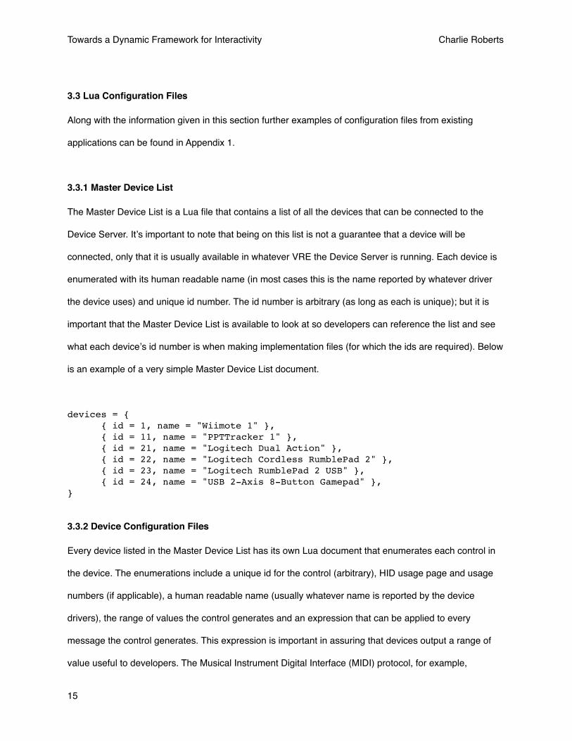
3.3.1 Master Device List
The Master Device List is a Lua file that contains a list of all the devices that can be connected to the
Device Server. Itʼs important to note that being on this list is not a guarantee that a device will be
connected, only that it is usually available in whatever VRE the Device Server is running. Each device is
enumerated with its human readable name (in most cases this is the name reported by whatever driver
the device uses) and unique id number. The id number is arbitrary (as long as each is unique); but it is
important that the Master Device List is available to look at so developers can reference the list and see
what each deviceʼs id number is when making implementation files (for which the ids are required). Below
is an example of a very simple Master Device List document.
devices = { { id = 1, name = "Wiimote 1" }, { id = 11, name = "PPTTracker 1" }, { id = 21, name = "Logitech Dual Action" }, { id = 22, name = "Logitech Cordless RumblePad 2" }, { id = 23, name = "Logitech RumblePad 2 USB" }, { id = 24, name = "USB 2-Axis 8-Button Gamepad" },}
3.3.2 Device Configuration Files
Every device listed in the Master Device List has its own Lua document that enumerates each control in
the device. The enumerations include a unique id for the control (arbitrary), HID usage page and usage
numbers (if applicable), a human readable name (usually whatever name is reported by the device
drivers), the range of values the control generates and an expression that can be applied to every
message the control generates. This expression is important in assuring that devices output a range of
value useful to developers. The Musical Instrument Digital Interface (MIDI) protocol, for example,
Towards a Dynamic Framework for Interactivity Charlie Roberts
15
specifies that most output values are seven bit numbers in the range of {0. 127}. With the exception of
controlling other MIDI devices, this range of values has very little practical usage. Changing these values
to the range {0, 1} with an expression at the device level removes the need for the expression to be
scattered throughout multiple application implementation files, or, even worse, for an application
developer to handle the scaling and offsetting in their own code. As another example, tracking systems
such as the WorldViz Precision Point Tracking (PPT) system used in the AlloSphere output the physical
location of a tracker object in three dimensional space. This output varies greatly in different installations
due differing physical sizes. In order to provide a constant range of values between multiple spaces the
device configuration files in each space could be configured to output values in the range of {-1, 1}. This
helps ensure the portability of applications between different VREs using the Device Server.
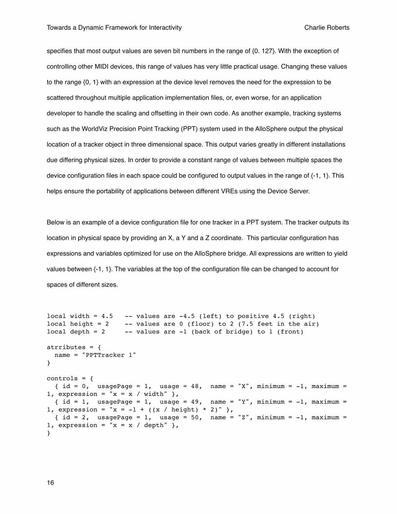
Below is an example of a device configuration file for one tracker in a PPT system. The tracker outputs its
location in physical space by providing an X, a Y and a Z coordinate. This particular configuration has
expressions and variables optimized for use on the AlloSphere bridge. All expressions are written to yield
values between {-1, 1}. The variables at the top of the configuration file can be changed to account for
spaces of different sizes.
local width = 4.5 -- values are -4.5 (left) to positive 4.5 (right)local height = 2 -- values are 0 (floor) to 2 (7.5 feet in the air)local depth = 2 -- values are -1 (back of bridge) to 1 (front)
atrributes = { name = "PPTTracker 1"}
controls = { { id = 0, usagePage = 1, usage = 48, name = "X", minimum = -1, maximum = 1, expression = "x = x / width" }, { id = 1, usagePage = 1, usage = 49, name = "Y", minimum = -1, maximum = 1, expression = "x = -1 + ((x / height) * 2)" }, { id = 2, usagePage = 1, usage = 50, name = "Z", minimum = -1, maximum = 1, expression = "x = x / depth" }, }
Towards a Dynamic Framework for Interactivity Charlie Roberts
16

The attributes dictionary is reserved for future use; one potential use of this dictionary will be to expose
force feedback mechanisms in devices.
3.3.3 Application Interface and Implementation Files
Each application has a single Interface file, named Interface.lua, that defines the functionalities the
application exposes. Each functionality is identified by a human readable name that will appear in the
Device Server GUI. The only additional information provided in this file is the range of values that the
client application is expecting to receive for each functionality. Knowing this range enables an important
feature of the Device Server: by knowing the range of values a device creates and knowing the range of
values an application expects to receive the Device Server can automatically offset and scale the signals
outputted by devices to the range client applications expect. Different controls on different devices can
easily be interchanged using the Device Server GUI knowing that the appropriate range of signals will
always be passed on to client applications. This encourages experimentation and play.
There can be multiple implementation files per application; users select which implementation they would
like to use on a per application basis through a pulldown menu in the Device Server GUI. Separate
implementation files are created to accommodate different configurations of devices. For example, one
implementation might use a wired joystick for control while another uses a wireless one. Users of an
application can also create separate implementation files that express their individual control preferences;
these files can saved from within the Device Server application at which point they will appear in the
application script pulldown menu for future use.
The implementation files contain a list of mappings that each correspond to a functionality defined in the
interface file for the application. Each mapping contains the name of an application functionality, a device
and a control (identified by id) that will feed that functionality, an expression that can be applied to the
signal from the device, an OSC address where the signal will be sent to, and a unique control ID number.
Towards a Dynamic Framework for Interactivity Charlie Roberts
17
The device number is retrieved from the Master Device List while the control number is gathered from the
deviceʼs configuration file. Expressions will be discussed in detail further on in this section.
The control ID number (called cID in the implementation file) is an arbitrary integer that is added to the
end of every OSC message sent out by the mapping. Its intended usage scenario is for when multiple
controls on different devices are routed to the same OSC address; the cID number can be used to
differentiate between the different signals. For example, letʼs say the client application is a multiplayer
game in which every player can “fire”. One way to handle this in the implementation file is to create a
separate OSC address for every player, e.g. “/fire1”, “/fire2”, “/fire3” etc. Another way to do this is to
assign all the messages to “/fire” but then have a different cID value for each of the different controls. If
the players are stored in an array in the client application using a cID makes life much easier for
development; developers just use the cID value to index which player in the array a particular control
message should affect.
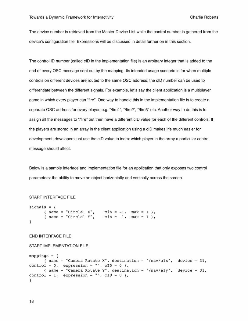
Below is a sample interface and implementation file for an application that only exposes two control
parameters: the ability to move an object horizontally and vertically across the screen.
START INTERFACE FILE
signals = { { name = "Circle1 X", min = -1, max = 1 }, { name = "Circle1 Y", min = -1, max = 1 }, }
END INTERFACE FILE
START IMPLEMENTATION FILE
mappings = { { name = "Camera Rotate X", destination = "/nav/a1x", device = 31, control = 0, expression = "", cID = 0 }, { name = "Camera Rotate Y", destination = "/nav/a1y", device = 31, control = 1, expression = "", cID = 0 },}
Towards a Dynamic Framework for Interactivity Charlie Roberts
18
END IMPLEMENTATION FILE
The location of interface and implementation files is a preference in the Device Server. When a client
application handshakes with the Device Server, the server looks in the location specified in the preference
sand then looks for a directory with the same name as the client application. It reads the Interface.lua file
from this directory and then immediately reads an implementation file called Default.lua. The default
implementation is in place so that users donʼt have to manually choose an implementation in the Device
Server GUI every time a client application launches; this one particular file will load automatically.
3.4 OSC Communication
OSC communication has four general purposes within the Device Server:
1. Connection and disconnection between clients and the Device Server
2. Sending mapped messages from the Device Server to client applications
3. Dynamically registering or unregistering to receive control messages from devices
4. Devices can communicated with the Device Server via OSC; one example of a device that does this
is the Apple iPhone.
3.4.1 Connecting and Disconnecting
The first message sent by any client app to the Device Server is the handshake message. This registers
the client application and tells the Device Server to load the applicationʼs implementation and interface
files. The arguments to the OSC message are the name of the client application, the IP address of the
computer the application is running on and the network port the application would like to receive the
messages at. A sample handshake would look like the following:
/handshake “Hydrogen Bond” “192.168.1.3” 9600
When applications are ready to terminate, they send a disconnection message:
/disconnectApplication “Hydrogen Bond”
Towards a Dynamic Framework for Interactivity Charlie Roberts
19

3.4.2 Sending Messages
In the Interface file specific OSC addresses are defined for each application functionality; when a mapped
control sends a signal to the Device Server it is routed to its appropriate destination using the IP address
and port of the application (provided when the application first shook hands with the Device Server) and
the OSC address from the interface file. A sample message might look as follows:
/changeCameraXOrientation .25 0
The first number is the processed value of the control. The second is the controID number, as described
in section 3.3.3.
3.4.3 Dynamically registering to receive control messages
Configuration files alone are not always enough to provide mappings for applications. When the number
of users and / or devices is not known configurations cannot be created that will take into account all
possible variations. For example, if users are asked to use their iPhones to control an application there
will likely be a different number of iPhones connected to the Device Server every time that application is
run depending on the number of users carrying iPhones.
The Device Server provides notifications to connected applications when new devices are added (or
removed) to the system; this notification includes the ID number of the device. The Master Device List
should account for the maximum possible number of devices that will be connected to the system at once
e.g. if it is possible that 30 iPhones may be connected to the Device Server then there should be thirty
iPhone entries in the Master Device List. The server then allows for applications to dynamically change
their mappings in order to account for new devices. A typical chain of events is illustrated below:
Towards a Dynamic Framework for Interactivity Charlie Roberts
20
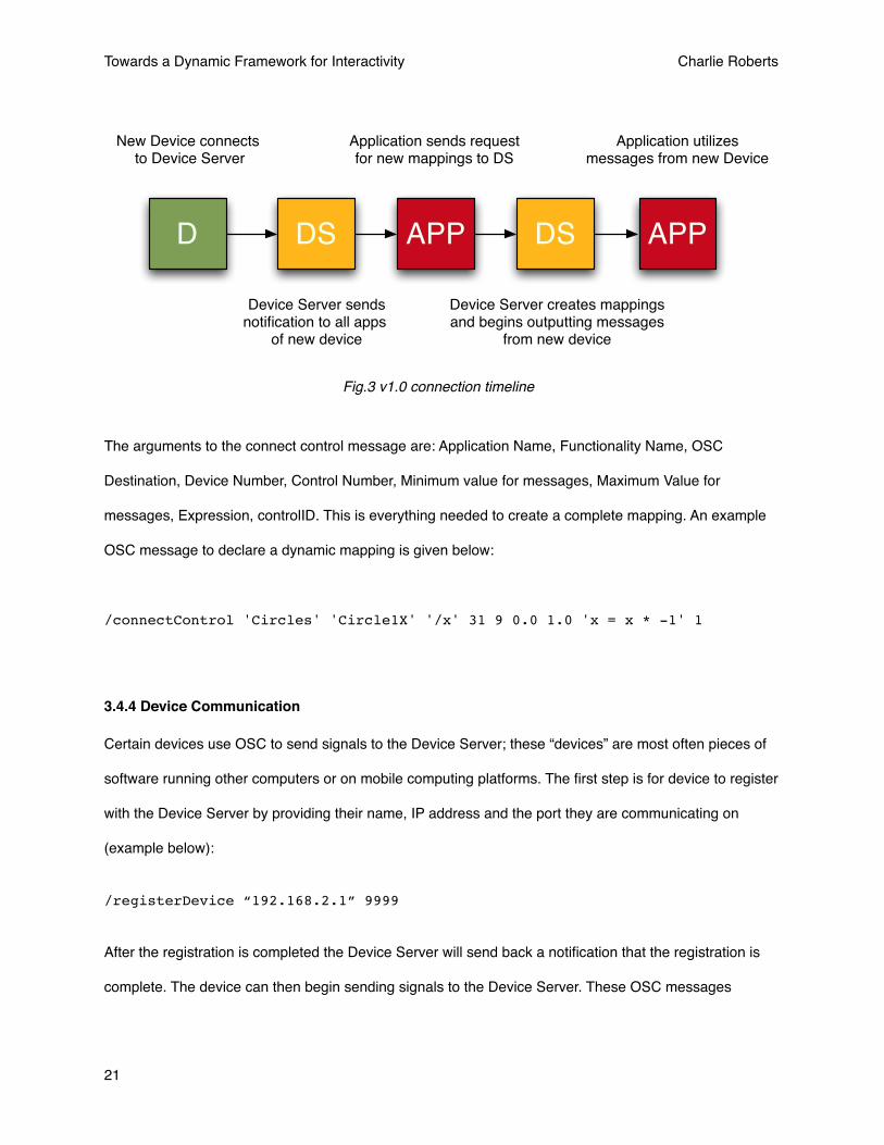
The arguments to the connect control message are: Application Name, Functionality Name, OSC
Destination, Device Number, Control Number, Minimum value for messages, Maximum Value for
messages, Expression, controlID. This is everything needed to create a complete mapping. An example
OSC message to declare a dynamic mapping is given below:
/connectControl 'Circles' 'Circle1X' '/x' 31 9 0.0 1.0 'x = x * -1' 1
3.4.4 Device Communication
Certain devices use OSC to send signals to the Device Server; these “devices” are most often pieces of
software running other computers or on mobile computing platforms. The first step is for device to register
with the Device Server by providing their name, IP address and the port they are communicating on
(example below):
/registerDevice “192.168.2.1” 9999
After the registration is completed the Device Server will send back a notification that the registration is
complete. The device can then begin sending signals to the Device Server. These OSC messages
D DS APP DS APP
New Device connects to Device Server
Device Server sends notification to all apps
of new device
Application sends request for new mappings to DS
Device Server creates mappingsand begins outputting messages
from new device
Application utilizes messages from new Device
Fig.3 v1.0 connection timeline
Towards a Dynamic Framework for Interactivity Charlie Roberts
21
contain three arguments: the name of the device, the name of the control issuing the signal, the value of
the signal (example below):
/OSCDeviceMsg “iPhone 1” “Slider 1” .5
When the device is disconnecting it should also send an OSC notification to the Device Server. Devices
can also be disconnected manually through the Device Server GUI in the event that a device crashes
before it is able to issue a notification.
3.5 Homogenizing Device Signals and Encouraging Experimentation
The Device Server uses the ranges described in mappings along with ranges in the device description
files to offset and scale the signal received from a device to match the range of values an application
functionality is expecting to receive. For example, analog joysticks often output a signal in the range {0,
255}. If an application mapping has a joystick is assigned to it but is expecting to receive a range of
values {-1, 1} the Device Server will take the value from the joystick, divide it by 255, multiply it by two and
then subtract one. Having the Device Server do this automatically means that, within reason, any control
on any device can be assigned to a mapping and still generate the range of values the application is
expecting to receive. For many cases this is only transformation necessary, but more complicated
transformations (non-linear, look-up-tables etc.) can also be completed using the Lua expression engine
described in 3.6. Although initial device and control mappings are created when an application
handshakes with the Device Server, the device and control assigned to a particular mapping may be
changed afterwards using pulldown menus in the Device Server GUI. Users can easily experiment with
using different devices / controls to control application parameters without having to recompile the client
application or modify Lua implementation files. When new mappings are found that are of interest they
can saved into new implementation files and recalled for later use. It is important that process of
experimenting with devices is as easy as possible so that users feel empowered to find the system of
controls that will make them most comfortable using visualizations.
Towards a Dynamic Framework for Interactivity Charlie Roberts
22
3.6 The Lua Expression Engine
The signals sent out by devices can be transformed through the usage of Lua expressions. Lua
functionality is currently included in the Device Server through the use of the LuaCore framework 10which
binds Lua to Objective-C. This allows Objective-C mapping objects to be passed into the Lua state, where
the expression for the mapping can be read in and executed. Lua expressions are used in a couple of
different parts of the Device Server; refer to Fig. 5 for a detailed diagram showing when and where device
signals are modified by Lua.
Expressions are normally placed in the implementation files for a client application, but can also be used
inside of device configuration files. The functions used in expressions can be stored in separate Lua files
and read into the Lua state in order to promote code reuse; for example, if every application was using a
table lookup function for a control it would make sense to have that function in a separate file that could
be included using Luaʼs dofile() function.
The format for an expression inside a mapping is as follows:
x = destroyDrift(x)
The variable x is both used as the number to feed destroyDrift() and is also the final return value; in this
case destroyDrift() is expected to return a value that will be assigned to x and used as the output. One
example of a destroyDrift function that would remove analog drift when a joystick is centered is below:
function destroyDrift(value) if(value > -.07 and value < .07) then return 0 else return x endend
Towards a Dynamic Framework for Interactivity Charlie Roberts
23
A complete example of an implementation file that uses this function can be found in Appendix 1. As
mentioned previously, Objective-C mapping objects are passed into the Lua state every time an
expression is evaluated. The object representing the client application is also passed in; this application
object contains an array of all the mappings associated with the application. By accessing this application
object any mapping can look at the previous value(s) of any other mapping. You can also access that
value of mappings before Lua expressions were applied to it (but after scaling and offsetting) or access
the raw signal of the device. Finally, you can print to the Device Server console from inside the Lua
expression engine. For a complete reference to Device Server specific Lua functionality, please see
Appendix 2.
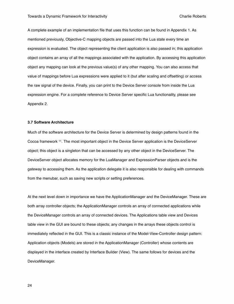
3.7 Software Architecture
Much of the software architecture for the Device Server is determined by design patterns found in the
Cocoa framework 11. The most important object in the Device Server application is the DeviceServer
object; this object is a singleton that can be accessed by any other object in the DeviceServer. The
DeviceServer object allocates memory for the LuaManager and ExpressionParser objects and is the
gateway to accessing them. As the application delegate it is also responsible for dealing with commands
from the menubar, such as saving new scripts or setting preferences.
At the next level down in importance we have the ApplicationManager and the DeviceManager. These are
both array controller objects; the ApplicationManager controls an array of connected applications while
the DeviceManager controls an array of connected devices. The Applications table view and Devices
table view in the GUI are bound to these objects; any changes in the arrays these objects control is
immediately reflected in the GUI. This is a classic instance of the Model-View-Controller design pattern:
Application objects (Models) are stored in the ApplicationManager (Controller) whose contents are
displayed in the interface created by Interface Builder (View). The same follows for devices and the
DeviceManager.
Towards a Dynamic Framework for Interactivity Charlie Roberts
24

Each Application object is a controller for an array of Mapping objects. Application objects are responsible
for reading in interface and implementation files (with the help of the LuaManager object that parses
them) and converting them into the appropriate set of Mapping objects.
Mapping objects have a number of responsibilities and, in many ways, do the bulk of the work in the
Device Server. When a signal travels from a device through the Device Server, the Mapping objects are
the last stop in the processing chain before an OSC message is sent to the client application.
Device objects are little more than glorified property lists. The only functionality they expose is returning id
numbers of controls based on their human readable names (and vice-versa), equality testing and a pretty
printing description method. They also store an array of dictionaries containing information about every
control in the device including the controlʼs name, its range of values and whether or not it has any
expressions associated with it. The actual generation of device objects and management of device drivers
is handled by plugins that are loaded by the BundleManager object which will be discussed shortly.
Towards a Dynamic Framework for Interactivity Charlie Roberts
25
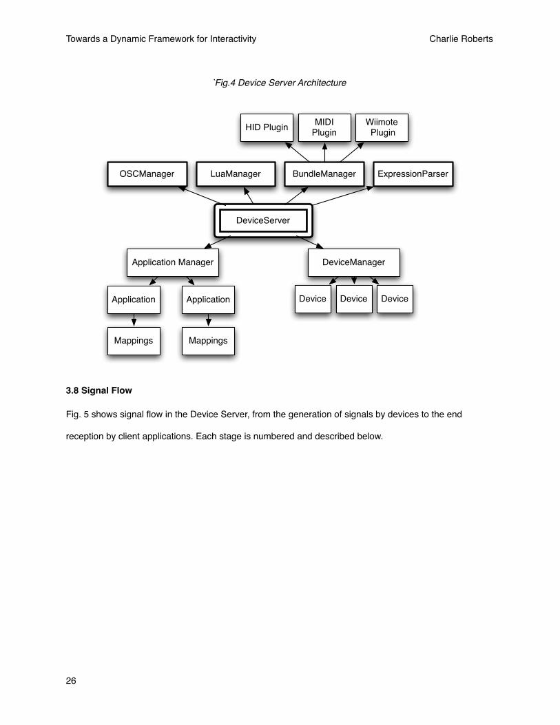
3.8 Signal Flow
Fig. 5 shows signal flow in the Device Server, from the generation of signals by devices to the end
reception by client applications. Each stage is numbered and described below.
`Fig.4 Device Server Architecture
DeviceServer
Application Manager DeviceManager
Device Device DeviceApplication Application
MappingsMappings
LuaManagerOSCManager BundleManager ExpressionParser
HID PluginMIDI
PluginWiimote Plugin
Towards a Dynamic Framework for Interactivity Charlie Roberts
26

Device
Device Configuration File
Application Interface File
Selected Implementation
File
Mapping Objects
Offset / Scaling
Lua Expression
Mapping rangeDevice range
Device Server
Key
Source / Destination
Output Viewable in Console
Signal Transformation
Lua Configuration File
Signal / Message
Information
MONITOR
MONITOR
MONITOR
Device Object
Device Expresssion
3
1
Application Manager 4
Application Objects
5
6
Client Applications
8
Device Plugin 2
OSCManager
7
1. A signal is generated by the device
2. The signal is read by the device plugin and passed to the device object representing it
Fig.5 Device Server Signal Flow
Towards a Dynamic Framework for Interactivity Charlie Roberts
27
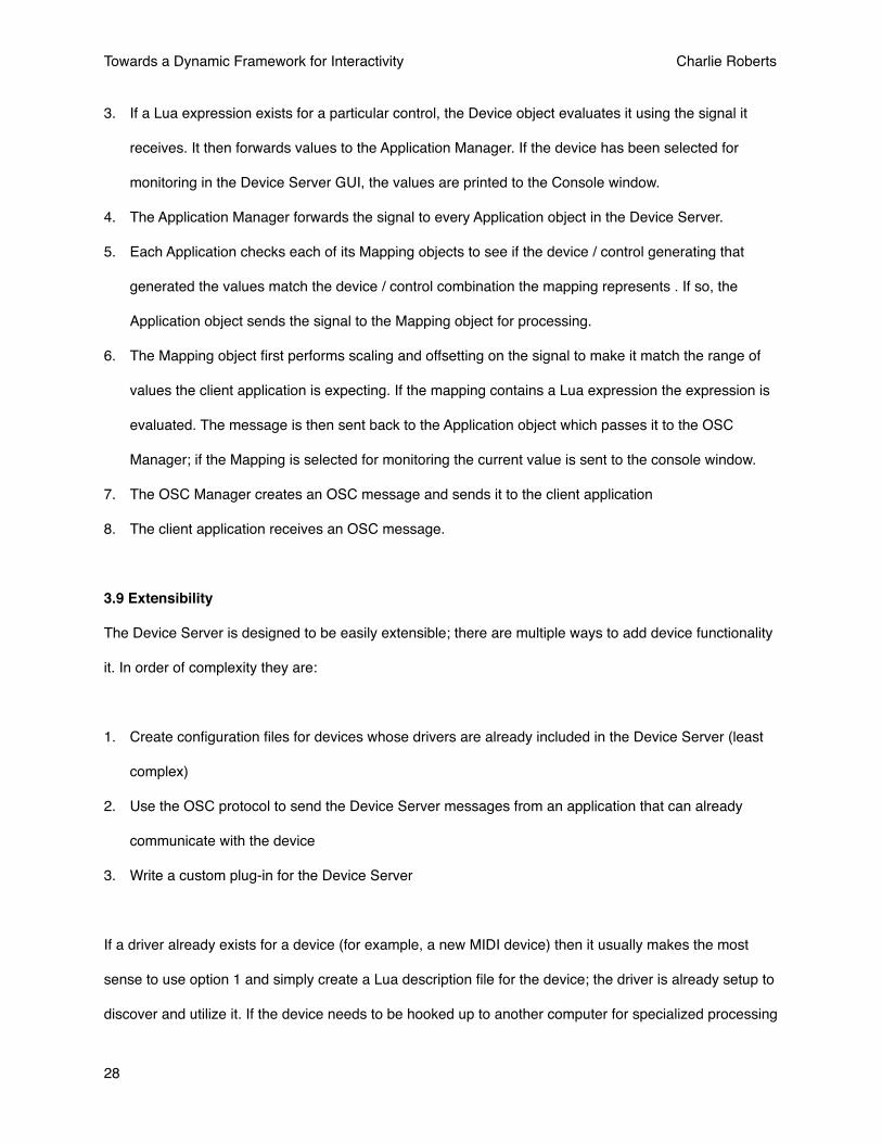
3. If a Lua expression exists for a particular control, the Device object evaluates it using the signal it
receives. It then forwards values to the Application Manager. If the device has been selected for
monitoring in the Device Server GUI, the values are printed to the Console window.
4. The Application Manager forwards the signal to every Application object in the Device Server.
5. Each Application checks each of its Mapping objects to see if the device / control generating that
generated the values match the device / control combination the mapping represents . If so, the
Application object sends the signal to the Mapping object for processing.
6. The Mapping object first performs scaling and offsetting on the signal to make it match the range of
values the client application is expecting. If the mapping contains a Lua expression the expression is
evaluated. The message is then sent back to the Application object which passes it to the OSC
Manager; if the Mapping is selected for monitoring the current value is sent to the console window.
7. The OSC Manager creates an OSC message and sends it to the client application
8. The client application receives an OSC message.
3.9 Extensibility
The Device Server is designed to be easily extensible; there are multiple ways to add device functionality
it. In order of complexity they are:
1. Create configuration files for devices whose drivers are already included in the Device Server (least
complex)
2. Use the OSC protocol to send the Device Server messages from an application that can already
communicate with the device
3. Write a custom plug-in for the Device Server
If a driver already exists for a device (for example, a new MIDI device) then it usually makes the most
sense to use option 1 and simply create a Lua description file for the device; the driver is already setup to
discover and utilize it. If the device needs to be hooked up to another computer for specialized processing
Towards a Dynamic Framework for Interactivity Charlie Roberts
28
(for example, a camera-based tracking system) then using the OSC protocol to communicate over the
network is a good choice. If no driver exists and the device is to be plugged in to the Device Server
directly, writing a plugin is the best option. Plugins are also the best option to use if a GUI is needed for
communication with the device.
Configuration files for devices are discussed in section 3.3.2 and the use of the OSC for devices is
covered in 3.4.4. The process of writing a custom plug-in is described below.
3.9.1 Device Server Plug-ins and the Bundle Manager
Device drivers were originally compiled straight into the Device Server application; recent versions of the
Device Server support the ability to dynamically load plug-ins containing drivers and GUIs needed to
communicate with devices. Using a plugin architecture keeps the Device Server modular and allows
developers to add new devices without having to modify the Device Server itself.
The Device Server comes with an XCode project template that automates the process of writing plug-ins.
The template contains a basic GUI hooked into a plug-in manager class with example code for how to
use the GUI and send device signals to applications. The plug-ins are NSBundle objects from the Cocoa
framework. They include a framework called DeviceServerBundle.framework that has all the necessary
header files to interface with the Device Server. There is also a flag that indicates whether or not an
optional GUI is included in the plug-in; in the current version of the Device Server the HID !!!plug-in does
not utilize a GUI while all other plug-ins do.
GUIs are often a necessary to interface with devices. For example, a Bluetooth pairing process needs to
be completed before you can use a Nintendo Wiimote with a personal computer. The pairing process
consists of telling the computer to scan for signals from Wiimotes and then pressing two buttons on the
Wiimote simultaneously to register it with the computer. Without a GUI of some sort there is no easy way
to tell the computer to begin the scanning process. The Wiimote plugin for the Device Server includes a
Towards a Dynamic Framework for Interactivity Charlie Roberts
29
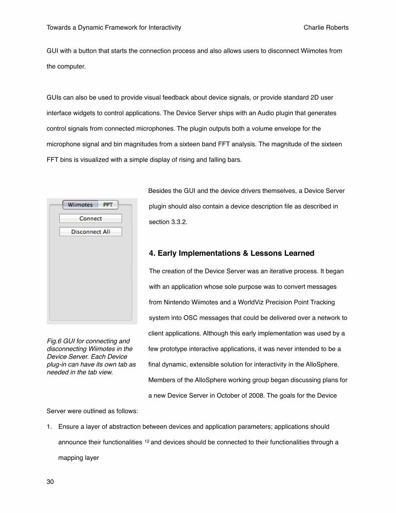
GUI with a button that starts the connection process and also allows users to disconnect Wiimotes from
the computer.
GUIs can also be used to provide visual feedback about device signals, or provide standard 2D user
interface widgets to control applications. The Device Server ships with an Audio plugin that generates
control signals from connected microphones. The plugin outputs both a volume envelope for the
microphone signal and bin magnitudes from a sixteen band FFT analysis. The magnitude of the sixteen
FFT bins is visualized with a simple display of rising and falling bars.
Besides the GUI and the device drivers themselves, a Device Server
plugin should also contain a device description file as described in
section 3.3.2.
4. Early Implementations & Lessons Learned
The creation of the Device Server was an iterative process. It began
with an application whose sole purpose was to convert messages
from Nintendo Wiimotes and a WorldViz Precision Point Tracking
system into OSC messages that could be delivered over a network to
client applications. Although this early implementation was used by a
few prototype interactive applications, it was never intended to be a
final dynamic, extensible solution for interactivity in the AlloSphere.
Members of the AlloSphere working group began discussing plans for
a new Device Server in October of 2008. The goals for the Device
Server were outlined as follows:
1. Ensure a layer of abstraction between devices and application parameters; applications should
announce their functionalities 12 and devices should be connected to their functionalities through a
mapping layer
Fig.6 GUI for connecting and disconnecting Wiimotes in the Device Server. Each Device plug-in can have its own tab as needed in the tab view.
Towards a Dynamic Framework for Interactivity Charlie Roberts
30
2. Provide a scripting mechanism for manipulating signals; this processing should occur on the server
and not in the client application
3. Centralize devices and device drivers to a single server; client applications only need to know a single
IP address / port to have access to every device in the system.
4. A Console should be present so that messages sent by devices can be monitored and displayed; this
helps troubleshoot device connectivity, driver issues and problems in the mapping layer.
The remainder of this section discusses features of versions 1.x and 2.x of the Device Server. Design
decisions involving the mapping abstraction layer, the GUI, configuration scripts and the techniques used
for parsing expressions are all discussed.
Towards a Dynamic Framework for Interactivity Charlie Roberts
31

4.1 Version 1.0
Version 1.0 (and subsequent versions) of the Device Server software was created for the OS X operating
system using Cocoa as its interface library. In v1.0, the mapping abstraction between applications and the
devices they were connected to was not implemented; applications connected to the devices they were
interested in explicitly by registering with the Device Server via OSC.
Natural to ApplicationMapper
User ApplicationUser OSC address
space
PPT System
Hardware
Software
ConceptualUnit
Joystick(s) Wireless
mappingregistrations
Status GUI
User Space
Device Space
OSC (user mapped)
User Natural[ /nav/x ] [ /joystick*/x * 2 - 1][ /nav/y ] [ /joystick*/y * 2 - 1][ /nav/run ] [ /joystick*/button1 ][ /agent1/call ] [ /wii*/button1 ]
multicast
Allosphere Core Device Server
(v. 1.0)
HIDOSC (natural)
Bluetooth
Device Integrator
OSC (config)
registrationsyntax(1 copy)
Key
Initial design diagram of the Device Server. Image by Lance Putnam
Towards a Dynamic Framework for Interactivity Charlie Roberts
32
There were two types of Extensible Markup Language (XML) configuration files used in v1.0. The first
was identical to the Master Device List currently used except that it is formatted in XML instead of Lua. A
small sample script is given below; the full Master Device List currently used in the AlloSphere currently
can be found in Appendix A.
<?xml version="1.0" encoding="UTF-8" ?><devices> <device id="1" name="Wiimote 1" /> <device id="2" name="PPTTracker 1" /> <device id="3" name="Logitech Dual Action" /> <device id="4" name="Logitech Cordless RumblePad 2" /></devices>
The second type of configuration file used describes device features; there is one XML document per
device connected to the Device Server. A small example for a PPT infrared tracker is provided below,
another example written in Lua and currently used in the AlloSphere can be found in Appendix A.
<?xml version="1.0" encoding="UTF-8" ?><device name="PPTTracker 1" type="OSC"> <control id="0" usagePage="1" usage="48" name="X" minimum="-1" maximum="1" range="2" expression="" /> <control id="1" usagePage="1" usage="49" name="Y" minimum="-1" maximum="1" range="2" expression="" /> <control id="2" usagePage="1" usage="50" name="Z" minimum="-1" maximum="1" range="2" expression="" /> </device>
Each signal output of the device is enumerated in the device description file. The enumeration assigns a
unique id number, identifies the usage page and usage number in the Human Interface Device (HID)
protocol, gives the human readable name of the control and the range of values that the control creates.
Once these configuration files were written, the Device Server was ready to operate and handle
connections. To create a connection to a particular control, a user would first “handshake” with the Device
Server using OSC; this handshake is identical to the handshake message used in v3.0. The messages
used to connect controls to the application are very similar what is used in v3.0 for dynamically registering
mappings. A sample OSC message for connecting a control in v1.0 given below:
Towards a Dynamic Framework for Interactivity Charlie Roberts
33
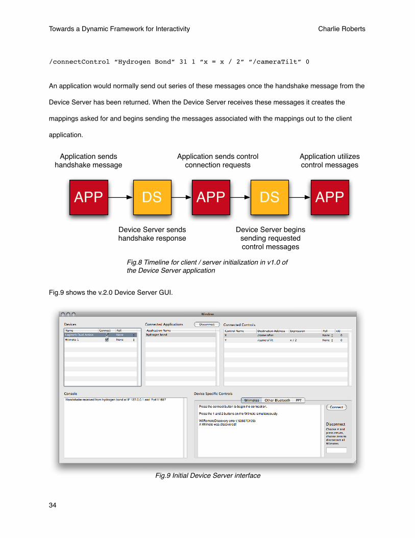
/connectControl “Hydrogen Bond” 31 1 “x = x / 2” “/cameraTilt” 0
An application would normally send out series of these messages once the handshake message from the
Device Server has been returned. When the Device Server receives these messages it creates the
mappings asked for and begins sending the messages associated with the mappings out to the client
application.
APP DS APP DS APP
Application sends handshake message
Device Server sendshandshake response
Application sends controlconnection requests
Device Server beginssending requested control messages
Application utilizes control messages
Fig.8 Timeline for client / server initialization in v1.0 of the Device Server application
Fig.9 shows the v.2.0 Device Server GUI.
Fig.9 Initial Device Server interface
Towards a Dynamic Framework for Interactivity Charlie Roberts
34
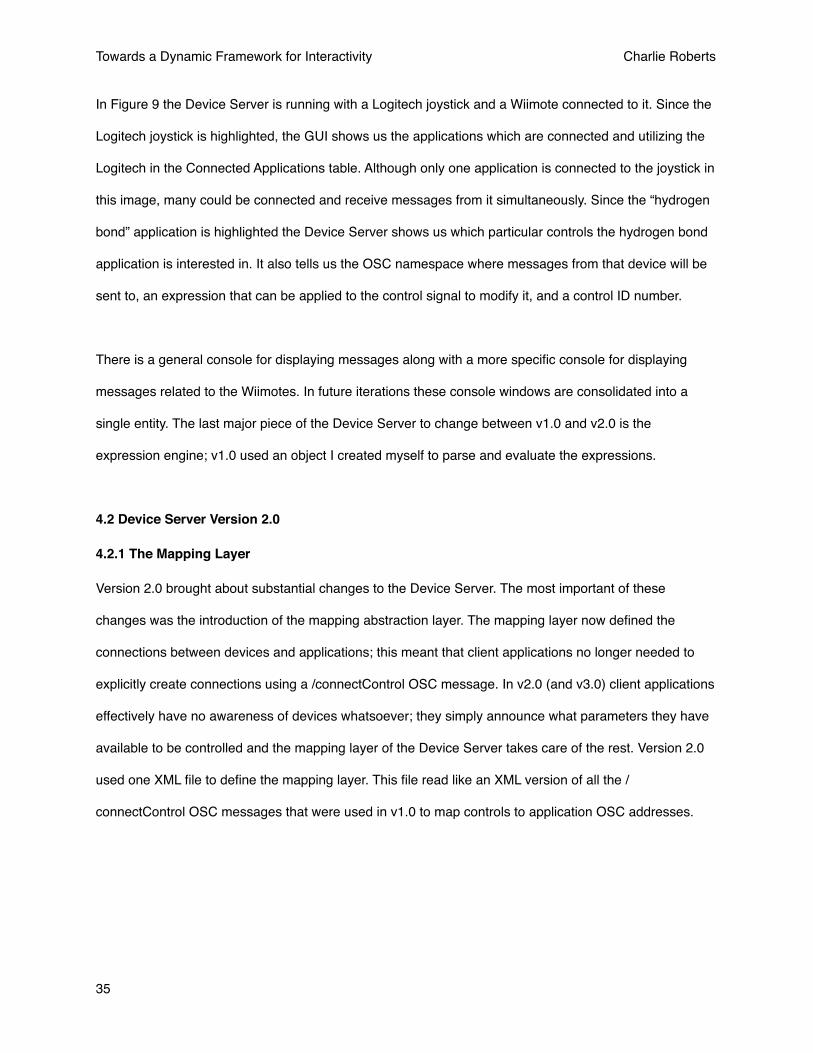
In Figure 9 the Device Server is running with a Logitech joystick and a Wiimote connected to it. Since the
Logitech joystick is highlighted, the GUI shows us the applications which are connected and utilizing the
Logitech in the Connected Applications table. Although only one application is connected to the joystick in
this image, many could be connected and receive messages from it simultaneously. Since the “hydrogen
bond” application is highlighted the Device Server shows us which particular controls the hydrogen bond
application is interested in. It also tells us the OSC namespace where messages from that device will be
sent to, an expression that can be applied to the control signal to modify it, and a control ID number.
There is a general console for displaying messages along with a more specific console for displaying
messages related to the Wiimotes. In future iterations these console windows are consolidated into a
single entity. The last major piece of the Device Server to change between v1.0 and v2.0 is the
expression engine; v1.0 used an object I created myself to parse and evaluate the expressions.
4.2 Device Server Version 2.0
4.2.1 The Mapping Layer
Version 2.0 brought about substantial changes to the Device Server. The most important of these
changes was the introduction of the mapping abstraction layer. The mapping layer now defined the
connections between devices and applications; this meant that client applications no longer needed to
explicitly create connections using a /connectControl OSC message. In v2.0 (and v3.0) client applications
effectively have no awareness of devices whatsoever; they simply announce what parameters they have
available to be controlled and the mapping layer of the Device Server takes care of the rest. Version 2.0
used one XML file to define the mapping layer. This file read like an XML version of all the /
connectControl OSC messages that were used in v1.0 to map controls to application OSC addresses.
Towards a Dynamic Framework for Interactivity Charlie Roberts
35

The addition of the mapping layer made the connection process much simpler; client applications simply
handshake with the Device Server as shown in Figure 10:
APP DS DS APP
Application sends handshake message
Device Server sendshandshake response
Device Server readsmapping configuration
Device Server beginssending configured control messages
Application utilizes control messages
DS
v2.0 also added the ability for users to change mappings in the GUI, and added the offsetting and scaling
to ensure that no matter what device and control is assigned to an application functionality that
functionality will always receive the range of values it expects (see section 3.5).
Below is an example of XML mapping document for a simple app that allows a joystick to control the
coordinates of an object on the screen.
<?xml version="1.0" encoding="UTF-8"?><mappings> <map destination="/X" device="31" control="0" min="-1" max="1" expression="" cID="0" /> <map destination="/Y" device="31" control="1" min="-1" max="1" expression="" cID="0" /></mappings>
4.2.2 Expression Engine
Another important change in v2.0 was the introduction of JavaScript based expression engine. By
including the WebKit library the Device Server was able to take advantage of the highly optimized
SquirrelFish JavaScript engine. This enabled more complex expressions to be written that were also more
efficient.
Fig.10 Device Server GUI
Towards a Dynamic Framework for Interactivity Charlie Roberts
36
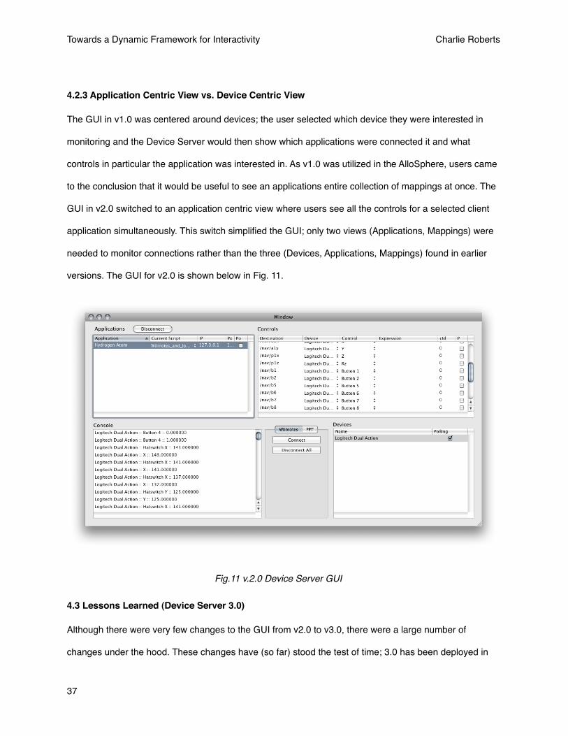
4.2.3 Application Centric View vs. Device Centric View
The GUI in v1.0 was centered around devices; the user selected which device they were interested in
monitoring and the Device Server would then show which applications were connected it and what
controls in particular the application was interested in. As v1.0 was utilized in the AlloSphere, users came
to the conclusion that it would be useful to see an applications entire collection of mappings at once. The
GUI in v2.0 switched to an application centric view where users see all the controls for a selected client
application simultaneously. This switch simplified the GUI; only two views (Applications, Mappings) were
needed to monitor connections rather than the three (Devices, Applications, Mappings) found in earlier
versions. The GUI for v2.0 is shown below in Fig. 11.
4.3 Lessons Learned (Device Server 3.0)
Although there were very few changes to the GUI from v2.0 to v3.0, there were a large number of
changes under the hood. These changes have (so far) stood the test of time; 3.0 has been deployed in
Fig.11 v.2.0 Device Server GUI
Towards a Dynamic Framework for Interactivity Charlie Roberts
37
the AlloSphere for about six months and no major changes to the software architecture have been
needed since deployment. The changes in v3.0 resulted from growing use in the AlloSphere; as more
applications were ported to rely on the Device Server for interactivity more developers began making
requests for new features or changes in functionality. These requests led to a number of notable
improvements in v3.0 which will be detailed in this section.
4.3.1 Moving from XML / JavaScript to Lua
In v2.0 of the Device Server XML was used for the configuration files and JavaScript was used for the
writing expressions. There was resistance to developers in the AlloSphere working group to using XML;
many preferred Lua as a data descriptor language. Although I was initially hesitant to put in the work to
change from XML to Lua, the more I studied the possibilities the more convinced I was that the change
was needed. This section outlines the many benefits of transitioning to Lua.
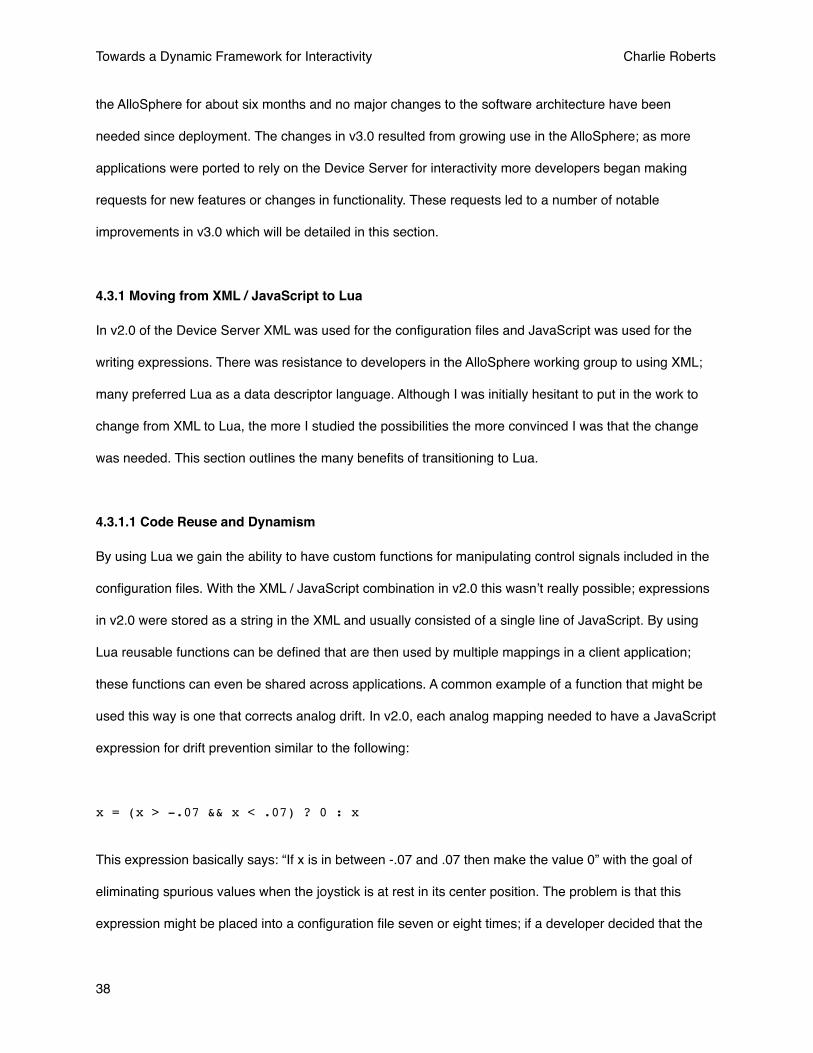
4.3.1.1 Code Reuse and Dynamism
By using Lua we gain the ability to have custom functions for manipulating control signals included in the
configuration files. With the XML / JavaScript combination in v2.0 this wasnʼt really possible; expressions
in v2.0 were stored as a string in the XML and usually consisted of a single line of JavaScript. By using
Lua reusable functions can be defined that are then used by multiple mappings in a client application;
these functions can even be shared across applications. A common example of a function that might be
used this way is one that corrects analog drift. In v2.0, each analog mapping needed to have a JavaScript
expression for drift prevention similar to the following:
x = (x > -.07 && x < .07) ? 0 : x
This expression basically says: “If x is in between -.07 and .07 then make the value 0” with the goal of
eliminating spurious values when the joystick is at rest in its center position. The problem is that this
expression might be placed into a configuration file seven or eight times; if a developer decided that the
Towards a Dynamic Framework for Interactivity Charlie Roberts
38
values should be {-.6, .6} instead of {-.7, .7} he or she would have to change the code eight times. Using
Lua we can define a function once, such as:
function destroyDrift(value) if(value > -.07 and value < .07) then return 0 else return x endend
Then the expression used in the mapping file just becomes x = destroyDrift(x). Developers can
now perform any needed modifications in the function rather than the expressions themselves; these
modifications will be instantly reflected in all mappings utilizing it.
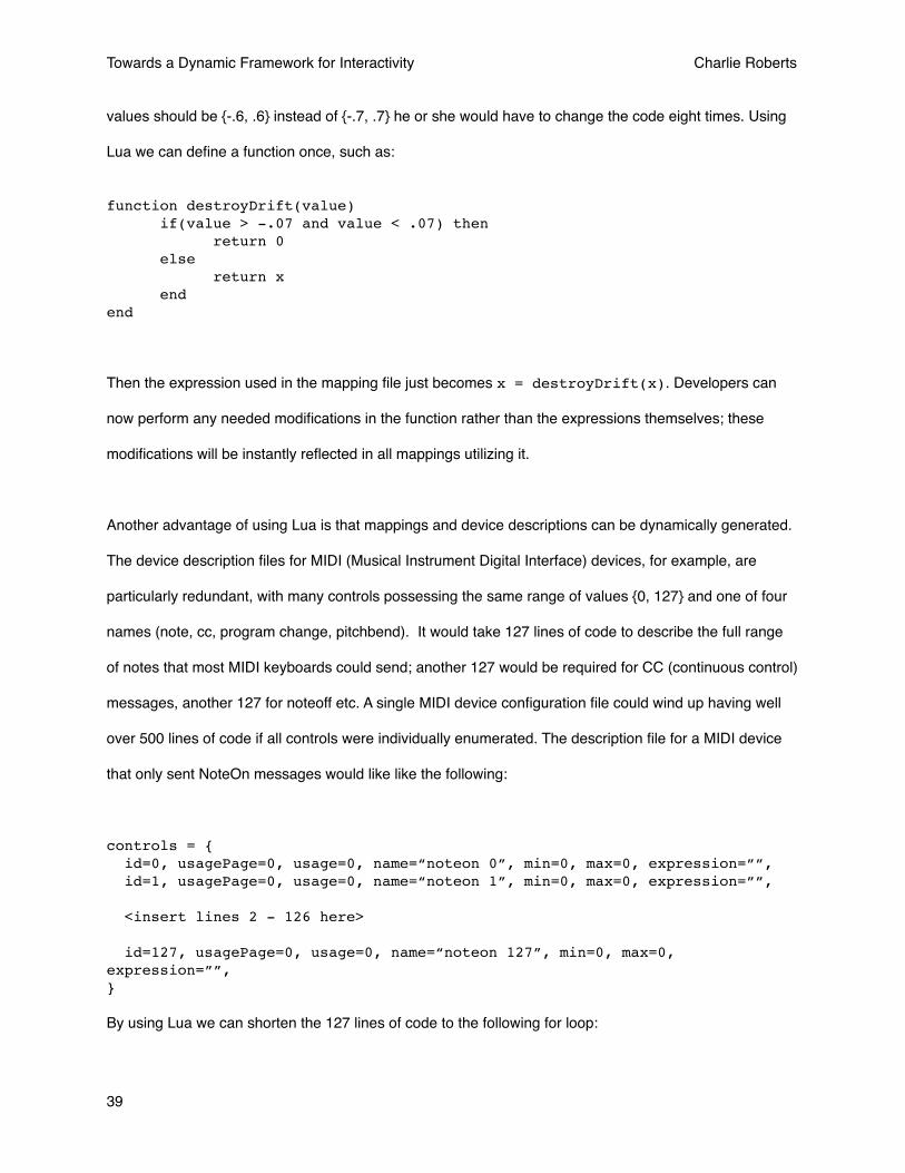
Another advantage of using Lua is that mappings and device descriptions can be dynamically generated.
The device description files for MIDI (Musical Instrument Digital Interface) devices, for example, are
particularly redundant, with many controls possessing the same range of values {0, 127} and one of four
names (note, cc, program change, pitchbend). It would take 127 lines of code to describe the full range
of notes that most MIDI keyboards could send; another 127 would be required for CC (continuous control)
messages, another 127 for noteoff etc. A single MIDI device configuration file could wind up having well
over 500 lines of code if all controls were individually enumerated. The description file for a MIDI device
that only sent NoteOn messages would like like the following:
controls = { id=0, usagePage=0, usage=0, name=“noteon 0”, min=0, max=0, expression=””, id=1, usagePage=0, usage=0, name=“noteon 1”, min=0, max=0, expression=””,
<insert lines 2 - 126 here>
id=127, usagePage=0, usage=0, name=“noteon 127”, min=0, max=0, expression=””,}
By using Lua we can shorten the 127 lines of code to the following for loop:
Towards a Dynamic Framework for Interactivity Charlie Roberts
39
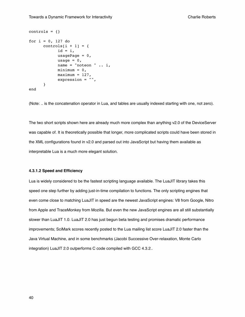
controls = {}
for i = 0, 127 do controls[i + 1] = { id = i, usagePage = 0, usage = 0, name = "noteon " .. i, minimum = 0, maximum = 127, expression = "", }end
(Note: .. is the concatenation operator in Lua, and tables are usually indexed starting with one, not zero).
The two short scripts shown here are already much more complex than anything v2.0 of the DeviceServer
was capable of. It is theoretically possible that longer, more complicated scripts could have been stored in
the XML configurations found in v2.0 and parsed out into JavaScript but having them available as
interpretable Lua is a much more elegant solution.
4.3.1.2 Speed and Efficiency
Lua is widely considered to be the fastest scripting language available. The LuaJIT library takes this
speed one step further by adding just-in-time compilation to functions. The only scripting engines that
even come close to matching LuaJIT in speed are the newest JavaScript engines: V8 from Google, Nitro
from Apple and TraceMonkey from Mozilla. But even the new JavaScript engines are all still substantially
slower than LuaJIT 1.0. LuaJIT 2.0 has just begun beta testing and promises dramatic performance
improvements; SciMark scores recently posted to the Lua mailing list score LuaJIT 2.0 faster than the
Java Virtual Machine, and in some benchmarks (Jacobi Successive Over-relaxation, Monte Carlo
integration) LuaJIT 2.0 outperforms C code compiled with GCC 4.3.2..
Towards a Dynamic Framework for Interactivity Charlie Roberts
40
By using LuaJIT in the Device Server application developers get very fast scripting of signal
transformations and the flexibility of changing scripts as much as they want without having to recompile
their application.
4.3.2 Abstracting the Abstraction Layer
One problem with the XML mappings file used in v2.0 was that many mappings wound up containing
identical sets of information. In particular, the range of values each mapping was expecting to receive was
identical between all the different mapping configuration files for a given application. if an application
changes the controls that were available to it, or changes the accepted range of signals it wants to see,
then mappings in all the separate configuration files would have to be changed individually. The solution
for this in v3.0 was to place all the static information associated with mappings into a separated file, which
was termed the Interface file for the application. The information that might change for mappings (which
device / control was connected, expressions to be applied to the signal etc.) was placed in
Implementation files. For example, you might have one implementation that uses a wired joystick for
navigation, another that used a wireless joystick and a third that used a MIDI device. Each of these
configurations would have its own implementation file but all would look to the same interface file to
determine what controls were available for mapping and what range of values each control was expecting
to receive. The implementation and interface files for v3.0 are described in detail in section 3.3.3.
4.3.3 Device Driver Plugins
Prior to v3.0, device drivers were hardcoded into the Device Server project. This meant the Device Server
itself had to be modified in order use new devices. In v3.0, there is a plugin system that allows developers
to write their own modular device driver for the Device Server. Developers can use an XCode template
that comes with a framework giving them access to all the main objects in the Device Server application.
Simple GUIs can be added if communication with devices is needed; for example, a handshake message
has to be sent to the PPT system. The drivers and the GUIs are dynamically loaded when the Device
Server first begins running. The plugin system is described in detail in section 3.9.1.
Towards a Dynamic Framework for Interactivity Charlie Roberts
41
5. Comparison and Evaluation
In Section 2 various alternatives to the Device Server were discussed; in this section they will be explicitly
compared to the Device Server. Most of the discussion will be dedicated to VRPN; many of the
architectural differences between the Device Server and VRPN are also present in VRui and Gadgeteer.
The Mapping tools of the Digital Orchestra Toolbox will also receive a more detailed treatment as it is
conceptually most similar to the Device Server of all the frameworks reviewed. User feedback and latency
concerns will also be discussed.
5.2.1 VRPN
VRPN is perhaps the most widely used framework for interactivity. There are fundamental design
differences in the architecture between VRPN that create benefits and drawbacks to using either platform.
5.2.1.1 Dynamism
With the Device Server no recompilation is necessary to change what device is feeding your application;
you simply change the implementation file for your app and refresh the script. This allows for a level of
experimentation with devices that would be difficult to achieve in a static setup (mapping tools reference).
In a multiuser setup dynamism becomes particularly important. If you have five users in a VR environment
and each user is experimenting with different roles and different devices, it would be practically
impossible to configure with a server that could not be dynamically configured. Every time a person would
want to change a device or the filtering of a device signal in some way the entire application would have
to be recompiled. The Device Server provides a very fluid way to deal with these issues by giving a GUI
to select which devices / controls are assigned to which application functionalities. Lua scripts can also be
modified and refreshed via the Device Server GUI while the application is running.
In their article "Using a scripting engine to facilitate the development of force fields in a distributed haptic
setup"13 the authors talk about their efforts to bring dynamism to VRPN. They created a custom VRPN
Towards a Dynamic Framework for Interactivity Charlie Roberts
42
force-field server object that interpreted Lua code sent to it by clients after a connection link had been
established. This type of functionality is available within the Device Server out of the box. Change the Lua
script assigned to a mapping, hit refresh, and you're done.
This dynamism also includes introduction of devices into virtual environments. Mobile devices can be
dynamically introduced to the Device Server and immediately utilized by running applications, who are
automatically sent notification of their introduction. Applications are also sent a notification whenever
devices are disconnected so that they can respond accordingly.
5.2.1.2 OSC
Although not necessarily an advantage for computer scientists, choosing OSC as the communication
protocol for the Device Server greatly eases using devices for artists, musicians and hybrid engineers. As
of this writing, Max/MSP is the only common prototyping library used that has a library or object for
handling VRPN connections. Pd, Processing, Quartz Composer and OpenFrameworks all have excellent
support for OSC communication.
5.2.1.3 Device Agnosticism
In VRPN there are several different classes of devices; when you register to receive messages from one
type of device and assign it to control parameters of your application that's the only type of device that
can be used for that callback. There are exceptions, but they are what might be called "hacks"; for
example, the vrpn_AnalogFly object takes in messages from a joystick and outputs vrpn_Tracker
messages. Any conversion between different types of devices requires this type of specialized, compiled
object to be created in VRPN. With the Device Server, all signals are treated equally and any object can
be used to feed any parameter of an application.
The downside to this is that itʼs not possible to easily switch one entire device for another in the Device
Server because it doesnʼt have that extra layer of abstraction present (classes of devices). Switching
Towards a Dynamic Framework for Interactivity Charlie Roberts
43

individual controls is easier, including switching from one button to another button on the same device,
but switching an entire device is more difficult.
5.2.1.4 Distributed Servers, Latency and GUIs
There is no GUI application available to establish and monitor VRPN connections between devices. This
is possibly due to differences in the client / server models between VRPN and the Device Server. The
Device Server has one centralized aggregation point for all devices in a system; VRPN does not have any
such aggregation point out of the box. Rather, VRPN assumes that client applications will connect directly
to computers that are serving up device signals. A simplified comparison of the interfaces in the two
architectures is given below in Fig. 12.
Without a centralized aggregation point, there is no easy computer to locate a GUI based monitoring app
on. A special VRPN (a VRPN Server is a program that sends out signals from one or more devices) could
VRPN Device Server
Device Device Device
Server Server
Client Client Client
Device Device Device
Client Client Client
Server
Device
Host
Fig.12 Device Server / VRPN comparison
Towards a Dynamic Framework for Interactivity Charlie Roberts
44
be specially configured to aggregate the signals of other VRPN servers, but no server like this has been
created as of yet.
The VRPN model is in some cases a lower latency model than the Device Server as clients almost
always have direct network connections to the computers hosting the devices. In Fig. 12 one of the
devices has an intermediary computer that it is hosted on; an example of this in the AlloSphere is the
WorldViz PPT system. The cameras are hooked up to a dedicated computer that performs the computer
vision analysis necessary to obtain the three dimensional coordinates of each tracking device. This
coordinate information is then sent to the Device Server, which in turn sends it out to client applications.
In a typical VRPN setup the client applications would be interfaced directly with the computer performing
the vision processing; this would avoid one network hop and the associated overhead.
A final disadvantage of having multiple servers (as in VRPN) is that there is potentially a large number of
IP addresses that a client application needs to be aware of as opposed to the single IP address needed
when using the Device Server.
5.2.1.5 Control Signal Processing
The Device Server features the ability to write custom expressions for control processing; these
expressions are dynamic and can be adjusted without having to recompile a client application. Although it
is definitely possible to perform control signal processing using a VRPN, any adjustment of the
processing will require the developers to recompile their VRPN server. It is possible to embed a scripting
engine into a VRPN plugin (earlier force-field reference), but it is extra work that would be required for
every single device in a interactive system.
5.2.2 Gadgeteer
Gadgeteer has the same device abstraction layer that VRPN has with the same costs and benefits.
Devices of the same type can easily be interchanged, but mixing and matching individual control objects
Towards a Dynamic Framework for Interactivity Charlie Roberts
45
becomes difficult. In Gadgeteer, abstract device categories also have predefined ranges of output, for
example, devices of type Analog always return a floating point number in the range of {0, 1}. This means
controls in a client application have to be hardwired to accept a range of values that will not apply to other
abstract input types. If a control in an application only knows how to use numbers from {0, 1} there is no
way for it to successfully process, for example, positional data measured in meters.
5.2.3 VRui As mentioned in 2.1 VRui has an extra layer of abstraction called tools. In effect, a tool is a meta device; a
tool combines the controls of multiple devices into a single interface and also states a functionality for the
aggregation. In VRPN and Gadgeteer individual devices can be swapped for one another if they are of
the same type; VRui takes this one step further by allowing collections of devices and controls that
represent functionalities to be interchanged easily.
5.2.4 DIVERSE ToolKit (DTK)
The DIVERSE (Device Independent Virtual Environments- Reconfigurable, Scalable, Extensible) ToolKit
14(DTK) provides an architecture similar to other virtual reality frameworks mentioned in this thesis. It
distinguishes itself by using a shared object memory model for distribution instead of a client / server
messaging model.
There is no GUI for the DTK. Device objects are treated as dynamic shared objects, and thus can be
loaded and unloaded at runtime. This allows servers to be reconfigured and different devices to be
connected to running applications without the need for recompilation. However, the loading and unloading
of devices is all done through the command line and there are no monitoring mechanisms for examining
signals and troubleshooting them.
The DTK does not provide any mechanism for transformation of control values.
Towards a Dynamic Framework for Interactivity Charlie Roberts
46

5.2.5 Mapping tools of the Digital Orchestra Toolbox
The DOT mapping tools are conceptually closest to the Device Server of all the frameworks compared.
However, there are still fundamental differences between the two. The DOT mapping tools thinks of every
object that it manages connections for as a device. Devices in the mapping tools can have both inputs
and outputs; interaction devices would typically only have outputs while applications would typically only
have inputs. This allows easy bi-directional communication to take place; a good example of when
communication would need to flow from application to device (rather than vice-versa) is force feedback.
The Device Server does not currently possess any mechanisms for force feedback. In many ways, the
DOT mapping tools solution of having all objects (applications and devices) treated as a collection of
inputs and outputs is a more elegant than having a distinction between the two that starts to breakdown
when bi-directional communication is necessitated.
The current implementation of the DOT mapping tools is also not intended to act as a server. There is no
way to have an application register with the mapping tools and automatically begin receiving messages;
users must manually load in an XML file after navigating to its container directory. With the Device Server,
the Default.lua implementation is loaded automatically upon receiving a handshake message and
messages are immediately transmitted from the Device Server. This is possible due to the directory
structure that the Device Server enforces for applications and their scripts; there is never a need to
search for implementation files. Running virtual environments in the AlloSphere is a complicated task;
adding an extra step of having users navigate to configuration files every time a new application is loaded
is not acceptable.
The Lua scripting environment of the Device Server provides a great deal more flexibility than the single
line expressions and static XML files of the DOT mapping tools.
Even though the DOT mapping tools framework was discovered many months after work on the Device
Server had begun, the similarities between the two is notable, particularly in comparison to the other
Towards a Dynamic Framework for Interactivity Charlie Roberts
47

frameworks described in this section. The Device Server also has a GUI that makes it easy to alter
connections between devices and applications. The Device Server also uses a data description format
(Lua instead of XML in the current version) to both describe devices and store the connections used in
applications. The similarities between the two are interesting considering that both were developed by
hybrid musicians / engineers instead of virtual reality researchers.
5.3 Latency
Latency of the Device Server was measured while fifteen accelerometers were running through the
Device Server simultaneously. Over the course of a hundred samples, the mean latency was found to be
.490 ms with a standard deviation of .169 ms while running on a dual core Mac Pro. The amount of
latency introduced by the Lua expression engine is variable according to the complexity of the script,
however, recent improvements to the JIT compilation in Lua are greatly increasing the speed of the
expression engine.
5.4 User Feedback
I conducted a short lesson on how to use the Device Server with (primarily) graduate students in the
Media Arts and Technology program at the University of California, Santa Barbara with different levels of
experience in regards to both programming and the use of interactive devices. Afterwards students were
asked to submit thoughts and opinions about the Device Server. All users reported that they would
consider using the Device Server for projects not running in the AlloSphere. The universal complaint was
regarding the need for documentation and examples:
• “step by step instruction, flowchart, and debug tips”,
• “create a video tutorial or/and make a web based listing, step by step of the process, breaking the
steps into chunks.”,
• “make/receive code in the general languages (should be easy since people have already completed
it) ... i.e. have a basic max patch on hand for max users, lua for lua users, etc”.
Towards a Dynamic Framework for Interactivity Charlie Roberts
48

Watching students attempt to use the Device Server led me to believe that the need for example client
applications and configuration files is the most critical of their concerns. As mentioned in the final
comment above, these example clients should come from a variety of platforms (Max/MSP, Pd,
Processing, C++, Lua etc.) so that everyone has a template ready to be altered and used. These
examples should be included in the source code repository.
6. Future Directions and Conclusion
I would prefer if the Device Server wasnʼt tied to Cocoa and OS X; i am most interested in porting the
Device Server to Java and some work has already been done to this effect. However, in terms of
application development time, Cocoa adds many luxuries that speed development. For example, there
was little code required to write the Application and Device array controllers; the array controller objects
included in Cocoa handle the addition and removal of objects and update attached displays in the Device
Server GUI with very little glue code required. Creating a plugin architecture was also relatively simple;
the NSBundle handles dynamic loading and unloading of objects at runtime. Still, I think it would spur
outside usage and development contributions if the Device Server was not platform specific. There is also
a much larger community of Java developers than Objective-C developers to get involved in the project.
There are a number of reasons I would prefer to port the Device Server to Java rather than C++. With
Java, there is no need to worry about platform specific drivers for MIDI, HID etc. The Java drivers will
work cross-platform; not having to worry about platform specific driver issues is another major advantage
of initially limiting myself to OS X development. VRPN illustrates this problem perfectly as the VRPN
library contains many classes that only function under one operating system. The most recent version as
of the time of this writing, v 7.22, was the first to add HID support for OS X and there are many other
devices that only work under Windows. Java also provides a unified GUI development environment with
Swing whereas C++ possesses a myriad of GUI options (Qt, wxWidgets, GTK, etc.). If the Device Server
used Swing all Java developers would have at least some experience with GUI programming; there is no
similar alternative for C++ that all developers would be familiar with.
Towards a Dynamic Framework for Interactivity Charlie Roberts
49
The device abstraction layers found in the other frameworks (VRPN, VRui etc) yield interesting benefits
that should be explored. I would like to figure out a way to provide similar abstractions in the Device
Server without sacrificing the ability to have any control replace any other control in a mapping. I am
particularly interested in the tools concept found in VRui; that is, the ability group devices and controls
into units defined by their functionality rather than the controls they present. The ability to quickly map a
navigation tool to camera movement in a VRE would be an excellent addition to the Device Server.
I am interested in adding a full eatured back-end for VRPN to the Device Server. I believe the VRPN
community could benefit from the configuration abstractions and scripting capabilities that the Device
Server has to offer. Although it would require some hacks to get working, creating a VRPN based Device
Server would be a valuable contribution to the virtual reality community.
A final goal is to make the Device Server easier for artists and musicians as opposed to developers. The
ability to dynamically configure performance applications to accept a variety of controls and devices
would be valuable in the digital arts community. However, there are currently some significant barriers to
entry to use the Device Server; the most significant of these is the ability to program in Lua. Although it is
very easy to change configurations and save them on-the-fly with the Device Server, the initial
configuration files must currently be created in a text editor. One possibility for simplification is to augment
the Device Server GUI so that it is capable of creating interface and implementation files from scratch.
This would allow users to avoid having to use Lua for configuration purposes although they would still
need to learn basic Lua syntax if they needed to write custom expressions for transforming control
signals.
Conclusion
The Device Server provides a dynamic, scalable solution for multi-user interactivity. As compared to other
VR interactive frameworks its dynamism encourages users to experiment with interactivity by simplifying
Towards a Dynamic Framework for Interactivity Charlie Roberts
50

the process of experimentation. Users can change control configurations via simple pull-down menus
without having to recompile or reprogram applications. The Device Server homogenizes the values sent
from devices to applications so that users donʼt have to worry about the signals different devices emit;
they are all transformed to the ranges expected by client applications. This dynamism is of great value in
multi-user setups as it is relatively straightforward to change the functionalities assigned to different
devices and the roles of users employing them. Once changed these configurations can be easily saved
and recalled for future use.
The Device Server assists VRE developers by managing the disparate protocols used to communicate
with interactive devices. Instead of worrying about how to programmatically include device drivers into
VREs developers can concentrate on the interactive affordances of different devices and how best to
utilize them. Developers also benefit from the Lua scripting environment which allows them to offload the
transformation of control signals onto to the Device Server so that the CPUs of rendering computers are
not taxed. Finally, developers are not required to create different versions of their software in order to
accommodate different devices; the Device Server handles all device configuration concerns for them.
The Device Server benefits interactive system architectures by providing a single central location for all
device signals to be accessed. It allows multiple applications to access connected devices and provides a
convenient method for monitoring all connections and the signals traveling between them. Devices
requiring a dedicated computer for signal processing can forward messages to the Device Server post-
processing at which point they are available to all connected applications.
The Device Server is currently being used by multiple applications inside the AlloSphere scientific
instrument located at the University of California, Santa Barbara. Development and design of the Device
Server progresses iteratively and benefits from the input of both developers and VRE participants. Future
work on the server will focus on incorporating input abstractions found in other VR frameworks, opening
Towards a Dynamic Framework for Interactivity Charlie Roberts
51
development to outside developers and making the server as simple as possible for use in the digital arts
community.
Towards a Dynamic Framework for Interactivity Charlie Roberts
52
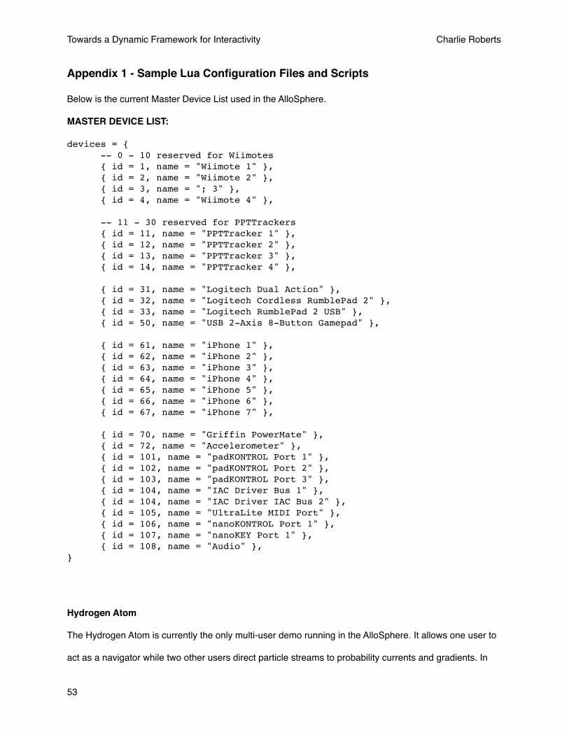
Appendix 1 - Sample Lua Configuration Files and Scripts
Below is the current Master Device List used in the AlloSphere.
MASTER DEVICE LIST:
devices = { -- 0 - 10 reserved for Wiimotes { id = 1, name = "Wiimote 1" }, { id = 2, name = "Wiimote 2" }, { id = 3, name = "; 3" }, { id = 4, name = "Wiimote 4" }, -- 11 - 30 reserved for PPTTrackers { id = 11, name = "PPTTracker 1" }, { id = 12, name = "PPTTracker 2" }, { id = 13, name = "PPTTracker 3" }, { id = 14, name = "PPTTracker 4" }, { id = 31, name = "Logitech Dual Action" }, { id = 32, name = "Logitech Cordless RumblePad 2" }, { id = 33, name = "Logitech RumblePad 2 USB" }, { id = 50, name = "USB 2-Axis 8-Button Gamepad" }, { id = 61, name = "iPhone 1" }, { id = 62, name = "iPhone 2" }, { id = 63, name = "iPhone 3" }, { id = 64, name = "iPhone 4" }, { id = 65, name = "iPhone 5" }, { id = 66, name = "iPhone 6" }, { id = 67, name = "iPhone 7" }, { id = 70, name = "Griffin PowerMate" }, { id = 72, name = "Accelerometer" }, { id = 101, name = "padKONTROL Port 1" }, { id = 102, name = "padKONTROL Port 2" }, { id = 103, name = "padKONTROL Port 3" }, { id = 104, name = "IAC Driver Bus 1" }, { id = 104, name = "IAC Driver IAC Bus 2" }, { id = 105, name = "UltraLite MIDI Port" }, { id = 106, name = "nanoKONTROL Port 1" }, { id = 107, name = "nanoKEY Port 1" }, { id = 108, name = "Audio" }, }
Hydrogen Atom
The Hydrogen Atom is currently the only multi-user demo running in the AlloSphere. It allows one user to
act as a navigator while two other users direct particle streams to probability currents and gradients. In
Towards a Dynamic Framework for Interactivity Charlie Roberts
53
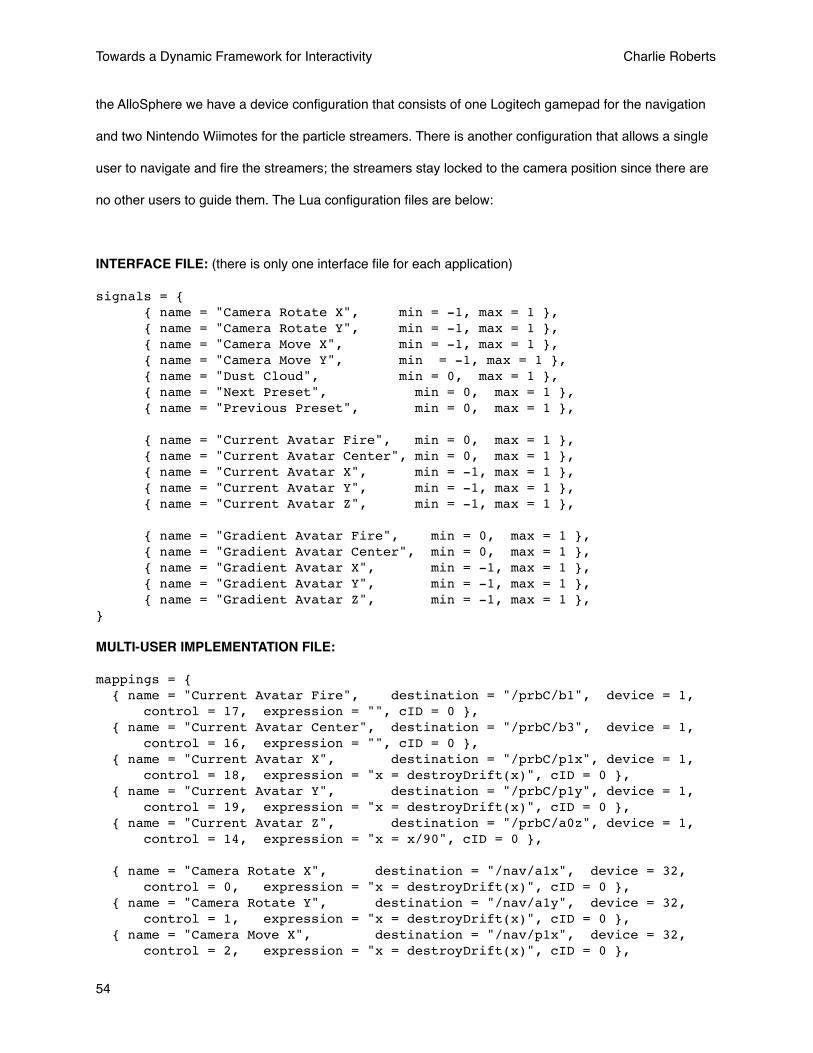
the AlloSphere we have a device configuration that consists of one Logitech gamepad for the navigation
and two Nintendo Wiimotes for the particle streamers. There is another configuration that allows a single
user to navigate and fire the streamers; the streamers stay locked to the camera position since there are
no other users to guide them. The Lua configuration files are below:
INTERFACE FILE: (there is only one interface file for each application)
signals = { { name = "Camera Rotate X", min = -1, max = 1 }, { name = "Camera Rotate Y", min = -1, max = 1 }, { name = "Camera Move X", min = -1, max = 1 }, { name = "Camera Move Y", min = -1, max = 1 }, { name = "Dust Cloud", min = 0, max = 1 }, { name = "Next Preset", min = 0, max = 1 }, { name = "Previous Preset", min = 0, max = 1 }, { name = "Current Avatar Fire", min = 0, max = 1 }, { name = "Current Avatar Center", min = 0, max = 1 }, { name = "Current Avatar X", min = -1, max = 1 }, { name = "Current Avatar Y", min = -1, max = 1 }, { name = "Current Avatar Z", min = -1, max = 1 }, { name = "Gradient Avatar Fire", min = 0, max = 1 }, { name = "Gradient Avatar Center", min = 0, max = 1 }, { name = "Gradient Avatar X", min = -1, max = 1 }, { name = "Gradient Avatar Y", min = -1, max = 1 }, { name = "Gradient Avatar Z", min = -1, max = 1 },}
MULTI-USER IMPLEMENTATION FILE:
mappings = { { name = "Current Avatar Fire", destination = "/prbC/b1", device = 1, control = 17, expression = "", cID = 0 }, { name = "Current Avatar Center", destination = "/prbC/b3", device = 1, control = 16, expression = "", cID = 0 }, { name = "Current Avatar X", destination = "/prbC/p1x", device = 1, control = 18, expression = "x = destroyDrift(x)", cID = 0 }, { name = "Current Avatar Y", destination = "/prbC/p1y", device = 1, control = 19, expression = "x = destroyDrift(x)", cID = 0 }, { name = "Current Avatar Z", destination = "/prbC/a0z", device = 1, control = 14, expression = "x = x/90", cID = 0 }, { name = "Camera Rotate X", destination = "/nav/a1x", device = 32, control = 0, expression = "x = destroyDrift(x)", cID = 0 }, { name = "Camera Rotate Y", destination = "/nav/a1y", device = 32, control = 1, expression = "x = destroyDrift(x)", cID = 0 }, { name = "Camera Move X", destination = "/nav/p1x", device = 32, control = 2, expression = "x = destroyDrift(x)", cID = 0 },
Towards a Dynamic Framework for Interactivity Charlie Roberts
54
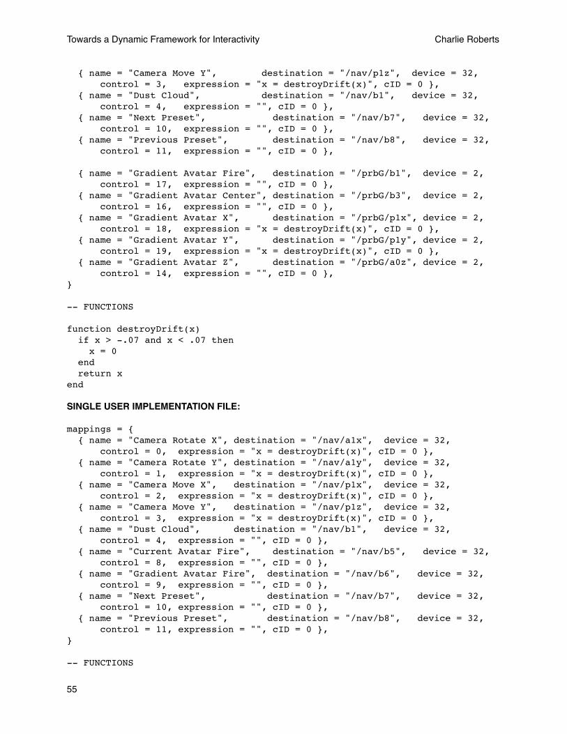
{ name = "Camera Move Y", destination = "/nav/p1z", device = 32, control = 3, expression = "x = destroyDrift(x)", cID = 0 }, { name = "Dust Cloud", destination = "/nav/b1", device = 32, control = 4, expression = "", cID = 0 }, { name = "Next Preset", destination = "/nav/b7", device = 32, control = 10, expression = "", cID = 0 }, { name = "Previous Preset", destination = "/nav/b8", device = 32, control = 11, expression = "", cID = 0 }, { name = "Gradient Avatar Fire", destination = "/prbG/b1", device = 2, control = 17, expression = "", cID = 0 }, { name = "Gradient Avatar Center", destination = "/prbG/b3", device = 2, control = 16, expression = "", cID = 0 }, { name = "Gradient Avatar X", destination = "/prbG/p1x", device = 2, control = 18, expression = "x = destroyDrift(x)", cID = 0 }, { name = "Gradient Avatar Y", destination = "/prbG/p1y", device = 2, control = 19, expression = "x = destroyDrift(x)", cID = 0 }, { name = "Gradient Avatar Z", destination = "/prbG/a0z", device = 2, control = 14, expression = "", cID = 0 },}
-- FUNCTIONS
function destroyDrift(x) if x > -.07 and x < .07 then x = 0 end return xend
SINGLE USER IMPLEMENTATION FILE:
mappings = { { name = "Camera Rotate X", destination = "/nav/a1x", device = 32, control = 0, expression = "x = destroyDrift(x)", cID = 0 }, { name = "Camera Rotate Y", destination = "/nav/a1y", device = 32, control = 1, expression = "x = destroyDrift(x)", cID = 0 }, { name = "Camera Move X", destination = "/nav/p1x", device = 32, control = 2, expression = "x = destroyDrift(x)", cID = 0 }, { name = "Camera Move Y", destination = "/nav/p1z", device = 32, control = 3, expression = "x = destroyDrift(x)", cID = 0 }, { name = "Dust Cloud", destination = "/nav/b1", device = 32, control = 4, expression = "", cID = 0 }, { name = "Current Avatar Fire", destination = "/nav/b5", device = 32, control = 8, expression = "", cID = 0 }, { name = "Gradient Avatar Fire", destination = "/nav/b6", device = 32, control = 9, expression = "", cID = 0 }, { name = "Next Preset", destination = "/nav/b7", device = 32, control = 10, expression = "", cID = 0 }, { name = "Previous Preset", destination = "/nav/b8", device = 32, control = 11, expression = "", cID = 0 },} -- FUNCTIONS
Towards a Dynamic Framework for Interactivity Charlie Roberts
55

function destroyDrift(x) if x > -.07 and x < .07 then x = 0 end return xend
EXAMPLE DEVICE CONFIGURATION DOCUMENT::
atrributes = { name = "Logitech Cordless RumblePad 2"}
controls = { { id = 0, usagePage = 1, usage = 48, name = "X", minimum = 0, maximum = 255, expression = "" }, { id = 1, usagePage = 1, usage = 49, name = "Y", minimum = 0, maximum = 255, expression = "" }, { id = 2, usagePage = 1, usage = 50, name = "Z", minimum = 0, maximum = 255, expression = "" }, { id = 3, usagePage = 1, usage = 53, name = "Rz", minimum = 0, maximum = 255, expression = "" }, { id = 4, usagePage = 9, usage = 1, name = "Button 1", minimum = 0, maximum = 1, expression = "" }, { id = 5, usagePage = 9, usage = 2, name = "Button 2", minimum = 0, maximum = 1, expression = "" }, { id = 6, usagePage = 9, usage = 3, name = "Button 3", minimum = 0, maximum = 1, expression = "" }, { id = 7, usagePage = 9, usage = 4, name = "Button 4", minimum = 0, maximum = 1, expression = "" }, { id = 8, usagePage = 9, usage = 5, name = "Button 5", minimum = 0, maximum = 1, expression = "" }, { id = 9, usagePage = 9, usage = 6, name = "Button 6", minimum = 0, maximum = 1, expression = "" }, { id = 10, usagePage = 9, usage = 7, name = "Button 7", minimum = 0, maximum = 1, expression = "" }, { id = 11, usagePage = 9, usage = 8, name = "Button 8", minimum = 0, maximum = 1, expression = "" }, { id = 12, usagePage = 9, usage = 9, name = "Button 9", minimum = 0, maximum = 1, expression = "" }, { id = 13, usagePage = 9, usage = 10, name = "Button 10", minimum = 0, maximum = 1, expression = "" }, { id = 14, usagePage = 9, usage = 11, name = "Button 11", minimum = 0, maximum = 1, expression = "" }, { id = 15, usagePage = 9, usage = 12, name = "Button 12", minimum = 0, maximum = 1, expression = "" }, { id = 16, usagePage = 1, usage = 57, name = "Hatswitch", minimum = 0, maximum = 8, expression = "" }, { id = 17, usagePage = 1, usage = 48, name = "Hatswitch X", minimum = 0, maximum = 255, expression = "" }, { id = 18, usagePage = 1, usage = 49, name = "Hatswitch Y", minimum = 0, maximum = 255, expression = "" },}
Towards a Dynamic Framework for Interactivity Charlie Roberts
56

Appendix 2 - Device Server Lua Scripting Reference
General UsageAll expressions are introduced in one of two places: the implementation files of an application or the device configuration files. An expression normally takes the following form:
x = x + (x / 2)
or
x = someFunctionName(x)
where someFunctionName is the name of a Lua function that has been defined in the implementation file. In these expressions, x represents both the final value passed to the application (hence it appears on the left side of the equal sign) and also the value passed into the expression to be used. If we call a Lua function in the expression, it needs to return a value for X to be passed to the application. An example of a function that will pass the highest value stored is given below:
highestValue = -10000
function getHighestValue(x) if x > highestValue then highestValue = x end return highestValueend
In the implementation file, this function would be called assigned in a mapping as follows:
expression = “x = getHighestValue(x)”
Console ObjectThe console object can be used to print to the console view in the Device Server Gui
Methods: print(aString)Example script:
console:print(“The value is “ .. x)
Mapping ObjectThe Mapping object represents the mapping that the Lua expression currently being evaluated belongs to. It contains a number of properties and access to the Application object. rawX() is a particularly useful method that gets the value of the signal feeding into the mapping before any offsetting, scaling or expressions have been performed. preExpressionValue() is another useful method used to get the value after offsetting and scaling but before the expression has been evaluated
Methods: min(), max(), scalar(), rawX(), preExpressionValue(), application(), deviceID(), controlID()
min() - the low end of the device signal range
max() - the high end of the device signal range
Towards a Dynamic Framework for Interactivity Charlie Roberts
57
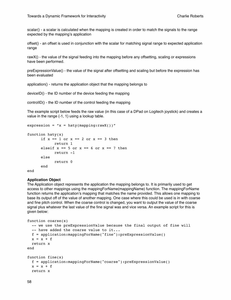
scalar() - a scalar is calculated when the mapping is created in order to match the signals to the range expected by the mappingʼs application
offset() - an offset is used in conjunction with the scalar for matching signal range to expected application range
rawX() - the value of the signal feeding into the mapping before any offsetting, scaling or expressions have been performed.
preExpressionValue() - the value of the signal after offsetting and scaling but before the expression has been evaluated
application() - returns the application object that the mapping belongs to
deviceID() - the ID number of the device feeding the mapping
controlID() - the ID number of the control feeding the mapping
The example script below feeds the raw value (in this case of a DPad on Logitech joystick) and creates a value in the range {-1, 1} using a lookup table.
expression = “x = haty(mapping:rawX())”
function haty(x) if x == 1 or x == 2 or x == 3 then return 1 elseif x == 5 or x == 6 or x == 7 then return -1 else return 0 endend
Application ObjectThe Application object represents the application the mapping belongs to. It is primarily used to get access to other mappings using the mappingForName(mappingName) function. The mappingForName function returns the applicationʼs mapping that matches the name provided. This allows one mapping to base its output off of the value of another mapping. One case where this could be used is in with coarse and fine pitch control. When the coarse control is changed, you want to output the value of the coarse signal plus whatever the last value of the fine signal was and vice versa. An example script for this is given below:
function coarse(x) -- we use the preExpressionValue because the final output of fine will -- have added the coarse value to it... f = application:mappingForName("fine"):preExpressionValue() x = x + f return xend
function fine(x) f = application:mappingForName("coarse"):preExpressionValue() x = x + f return x
Towards a Dynamic Framework for Interactivity Charlie Roberts
58
end
Constants
DNR - When a function returns DNR (Do Not Return) no value is sent out to applications. This can be used to create momentary triggers from continuous signals or to only send values under special circumstances. For example, if we only wanted to send a message when the volume of an audio signal was above a particular value we could do so as follows:
function audioThreshold(x) if x > .75 then return x else return DNR endend
gPwd - gPwd is a global that refers to the present working directory when used with application Implementation files. It is used to assist in code reuse. For example, the Device Server first loads a file called “Default.lua” when an application handshakes it. One common use for gPwd is for Default.lua to point to an existing script that is named descriptively. A simple Default.lua that loads another file is given below:
dofile(gPwd .. "Wireless No Wiimotes.lua")
dofile simply runs the script at the provided location.
Towards a Dynamic Framework for Interactivity Charlie Roberts
59
References
Towards a Dynamic Framework for Interactivity Charlie Roberts
60
1 Amatriain, X., Kuchera-Morin, J., Hollerer, T., Pope, S.T., "The AlloSphere: Immersive Multimedia for Scientific Discovery and Artistic Exploration”, IEEE MultiMedia, vol. 16, no. 2, pp. 64-75, Apr.-June 2009
2 Ierusalimschy, R., Figueiredo, L., Filho, W., “Lua—an extensible extension language”, Software—Practice & Experience, v.26 n.6, p.635-652, June 1996
3 Kreylos, O., “Environment-independent VR development”, In: Bebis, G., et al. (Eds.): Advances in Visual Computing, ISVC 2008, Part I, LNCS 5358, pp. 901–912, 2008
4 Oliver Kreylos' Research and Development Homepage - Vrui VR Toolkit. http://idav.ucdavis.edu/~okreylos/ResDev/Vrui/index.html
5 Gadgeteer: Device Driver Authoring Guide. Iowa State University: (2007)
6 Bierbaum, A., Just, C., Hartling, P., Meinert, K., Baker, A., Cruz-Neira, C., “Vr juggler: A virtual platform for virtual reality application development.” IEEE Virtual Reality. (2001)
7 Russell M. Taylor, II , Thomas C. Hudson , Adam Seeger , Hans Weber , Jeffrey Juliano , Aron T. Helser, “VRPN: a device-independent, network-transparent VR peripheral system”, Proceedings of the ACM symposium on Virtual reality software and technology, November 15-17, 2001, Baniff, Alberta, Canada
8 Malloch, Joseph, Stephen Sinclair, and Marcelo M. Wanderley. "A Network-Based Framework for Collaborative Development and Performance of Digital Musical Instruments." In R. Kronland- Martinet, S. Ystad, and K. Jensen (Eds.): CMMR 2007, - Proc. of Computer Music Modeling and Retrieval 2007 Conference, LNCS 4969. Berlin Heidelberg: Springer-Verlag, pp. 401–425, 2008
9 Wright, M., Freed, A., “Open Sound Control: A new protocol for communicating with sound synthesizers.” In Proceedings of the International Computer Music Conference, 1997.
10 LuaCore, a Cocoa wrapper to Lua. http://gusmueller.com/lua/
11 Cocoa Design Patterns. http://developer.apple.com/mac/library/DOCUMENTATION/Cocoa/Conceptual/CocoaFundamentals/CocoaDesignPatterns/CocoaDesignPatterns.htm
12 Wright, M., Freed, A., Lee, A., Madden, T. and Momeni, A., “Managing Complexity with Explicit Mapping of Gestures to Sound Control with OSC”, In International Computer Music Conference, (Habana, Cuba, 2001), 314--317. (http://cnmat.CNMAT.Berkeley.EDU/ICMC2001/pdf/OSC-GestureMap.2.pdf)
13 Raymaekers, C., De Weyere, T., Coninx, K., “Using a scripting engine to facilitate the development of force fields in a distributed haptic setup" In 3rd International Conference on Enactive Interfaces. (Montpellier, France), 81-82, 2006
14 Kelso, J., Satterfield, S., Arsenault, L., Ketchan, P., Kriz, R., “DIVERSE: A Framework for Building Extensible and Reconfigurable Device-Independent Virtual Environments and Distributed Asynchronous Simulations.” Presence: Teleoperators & Virtual Environments 2003 12:1, 19-36


![Mathematica Tutorial: Dynamic Interactivity · In[12]:= Slider@Dynamic@xDD Out[13]= This creates a new dynamic output of x since the last one has probably scrolled off your screen](https://img.dokumen.tips/doc/110x75/5fde489fd895e86b6b7d0d2b/mathematica-tutorial-dynamic-interactivity-in12-sliderdynamicxdd-out13.jpg)
![Towards Fully Reflective Environments · research community as well [13, 35]. However, even themetacircularapproachesproduceVMsthatdonot enable significant observability and interactivity](https://img.dokumen.tips/doc/110x75/5f598e381d59b41d8151f83a/towards-fully-reflective-environments-research-community-as-well-13-35-however.jpg)