Embed Size (px)
Citation preview

3A4350AEN
Operation
ToughTek™ CM-Series Continuous MixersElectric continuous mixer for water-based cementitious materials. For professional use only.
Not approved for use in explosive atmospheres or hazardous locations.
See Page 2 for model information.
Important Safety InstructionsRead all warnings and instructions in this and all related manuals. Save these instructions.
2 3A4350A
ContentsWarnings . . . . . . . . . . . . . . . . . . . . . . . . . . . . . . . . . 3Component Identification . . . . . . . . . . . . . . . . . . . . 5
CM-40 . . . . . . . . . . . . . . . . . . . . . . . . . . . . . . . . . 5CM-40 Silo . . . . . . . . . . . . . . . . . . . . . . . . . . . . . 6Control Box (J) . . . . . . . . . . . . . . . . . . . . . . . . . . 7Water Pump System (L) . . . . . . . . . . . . . . . . . . . 8Water Pressure Over-ride Plug (OP) . . . . . . . . . 9
Setup . . . . . . . . . . . . . . . . . . . . . . . . . . . . . . . . . . . . 10Grounding . . . . . . . . . . . . . . . . . . . . . . . . . . . . . 10
Operation . . . . . . . . . . . . . . . . . . . . . . . . . . . . . . . . 11Start Up . . . . . . . . . . . . . . . . . . . . . . . . . . . . . . . 11Mixing and Dispensing Material . . . . . . . . . . . . . 12Clean Out . . . . . . . . . . . . . . . . . . . . . . . . . . . . . 14Shutdown . . . . . . . . . . . . . . . . . . . . . . . . . . . . . . 15Routine Maintenance . . . . . . . . . . . . . . . . . . . . . 16
Butterfly Valve Mounting Pattern . . . . . . . . . . . . . 16Technical Specifications . . . . . . . . . . . . . . . . . . . . 17Graco Standard Warranty . . . . . . . . . . . . . . . . . . . 18
Models
Related Manuals
Manuals are available at www.graco.com
Model Part Description Power
CM-40 25M080 ToughTek CM-40 200-240 VAC, 1 Phase, 50 Hz
25M081 ToughTek CM-40 200-240 VAC, 1 Phase, 60 Hz
25M082 ToughTek CM-40 200-240 VAC, 3 Phase, 50 Hz
CM-40 Silo 25M085 ToughTek CM-40 Silo 200-240 VAC, 1 Phase, 50 Hz
25M086 ToughTek CM-40 Silo 200-240 VAC, 1 Phase, 60 Hz
25M087 ToughTek CM-40 Silo 200-240 VAC, 3 Phase, 50 Hz
Manual Description
3A3651 ToughTek P-Series Pumps

Warnings
3A4350A 3
WarningsThe following warnings are for the setup, use, grounding, maintenance, and repair of this equipment. The exclama-tion point symbol alerts you to a general warning and the hazard symbols refer to procedure-specific risks. When these symbols appear in the body of this manual or on warning labels, refer back to these Warnings. Product-specific hazard symbols and warnings not covered in this section may appear throughout the body of this manual where applicable.
WARNINGMOVING PARTS HAZARDMoving parts can pinch, cut or amputate fingers and other body parts.• Keep clear of moving parts.• Do not operate equipment with protective guards or covers removed.• Pressurized equipment can start without warning. Before checking, moving, or servicing equip-
ment, follow the Pressure Relief Procedure and disconnect all power sources.
ELECTRIC SHOCK HAZARDThis equipment must be grounded. Improper grounding, setup, or usage of the system can cause electric shock.• Turn off and disconnect power before servicing equipment.• Connect only to grounded electrical outlets.• Ensure ground prongs are intact.• Do not expose to rain. Store indoors.• All electrical wiring must be done by a qualified electrician and comply with all local codes and
regulations.
Warnings
4 3A4350A
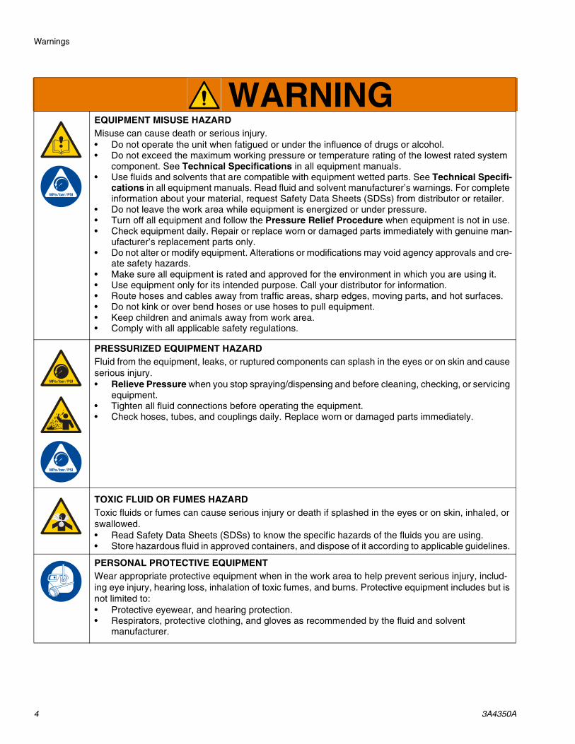
EQUIPMENT MISUSE HAZARDMisuse can cause death or serious injury.• Do not operate the unit when fatigued or under the influence of drugs or alcohol.• Do not exceed the maximum working pressure or temperature rating of the lowest rated system
component. See Technical Specifications in all equipment manuals.• Use fluids and solvents that are compatible with equipment wetted parts. See Technical Specifi-
cations in all equipment manuals. Read fluid and solvent manufacturer’s warnings. For complete information about your material, request Safety Data Sheets (SDSs) from distributor or retailer.
• Do not leave the work area while equipment is energized or under pressure.• Turn off all equipment and follow the Pressure Relief Procedure when equipment is not in use.• Check equipment daily. Repair or replace worn or damaged parts immediately with genuine man-
ufacturer’s replacement parts only.• Do not alter or modify equipment. Alterations or modifications may void agency approvals and cre-
ate safety hazards.• Make sure all equipment is rated and approved for the environment in which you are using it.• Use equipment only for its intended purpose. Call your distributor for information.• Route hoses and cables away from traffic areas, sharp edges, moving parts, and hot surfaces.• Do not kink or over bend hoses or use hoses to pull equipment.• Keep children and animals away from work area.• Comply with all applicable safety regulations.
PRESSURIZED EQUIPMENT HAZARDFluid from the equipment, leaks, or ruptured components can splash in the eyes or on skin and cause serious injury.• Relieve Pressure when you stop spraying/dispensing and before cleaning, checking, or servicing
equipment. • Tighten all fluid connections before operating the equipment.• Check hoses, tubes, and couplings daily. Replace worn or damaged parts immediately.
TOXIC FLUID OR FUMES HAZARDToxic fluids or fumes can cause serious injury or death if splashed in the eyes or on skin, inhaled, or swallowed.• Read Safety Data Sheets (SDSs) to know the specific hazards of the fluids you are using.• Store hazardous fluid in approved containers, and dispose of it according to applicable guidelines.
PERSONAL PROTECTIVE EQUIPMENTWear appropriate protective equipment when in the work area to help prevent serious injury, includ-ing eye injury, hearing loss, inhalation of toxic fumes, and burns. Protective equipment includes but is not limited to:• Protective eyewear, and hearing protection. • Respirators, protective clothing, and gloves as recommended by the fluid and solvent
manufacturer.
WARNING

Component Identification
3A4350A 5
Component Identification
CM-40
Ref. Description
A Mixing Tube Discharge Nozzle
B Mixing Shaft
C Mixing Tube
D Feed Screw
E Gearbox Motor
F Motor Cable
G Hopper Grate
H Hopper
J Control Box
K Wedge Retainer
L Water Pump System
M Power Cable
Ref. Description

Component Identification
6 3A4350A
CM-40 Silo
Ref. Description
A Mixing Tube Discharge Nozzle
B Mixing Shaft
C Mixing Tube
D Feed Screw
E Gearbox Motor
F Motor Cable
J Control Box
K Wedge Retainer
L Water Pump System
M Power Cable
Z Butterfly Valve
Ref. Description

Component Identification
3A4350A 7
Control Box (J)
ON
OFF
VFDFAULTWHEN
LIT
WATER PRIME
SPEED SELECTOR
WATER PSI
WATER PSIFWR REV1
23
WATER PUMPOFF ON
Ref. Description
N Main Power In Connector
P Power Out Connector
Q Main Power Disconnect Switch
R START/STOP Push Button
S Speed Selector Knob
T Forward/Reverse Mixer Direction Switch
U Water Prime Button
V Water Pressure Indicator
W Water Pump ON/OFF Switch
X Remote Switch Connector
Y Water Pressure Switch Plug
Ref. Description
Component Identification
8 3A4350A
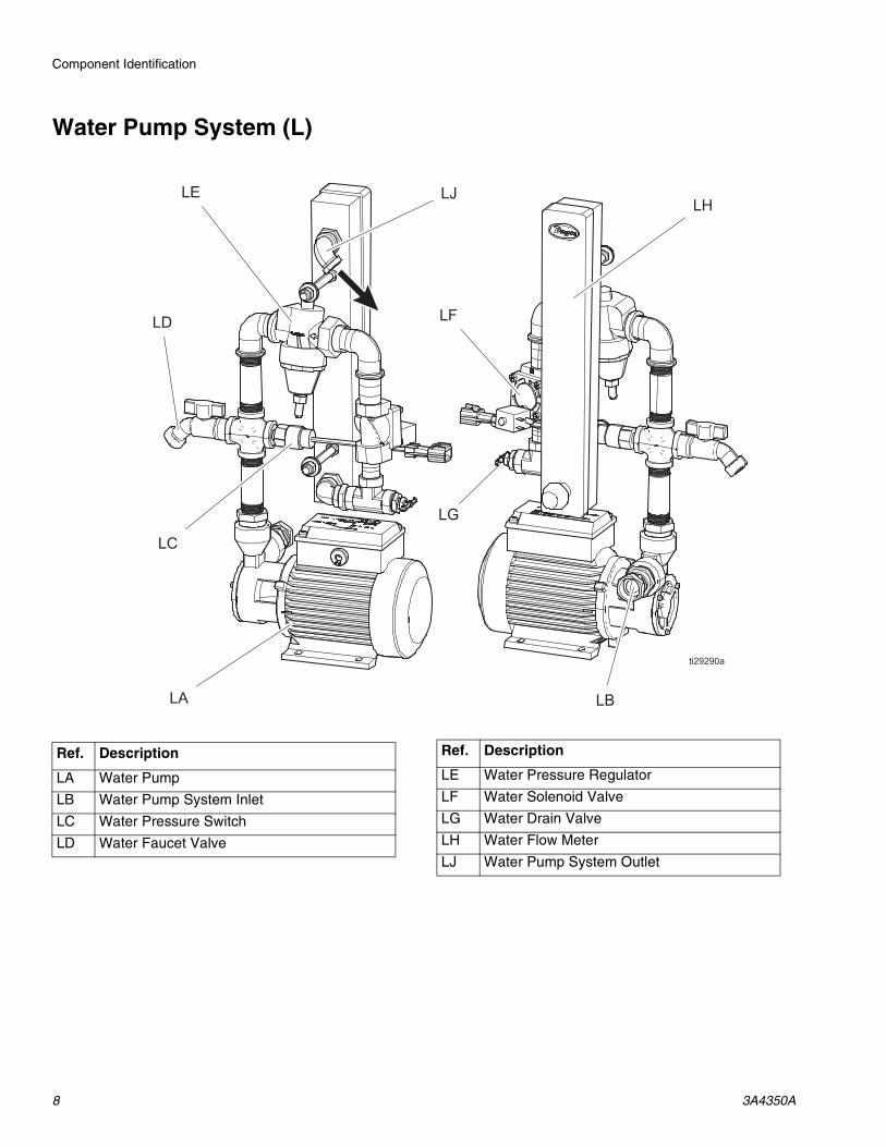
Water Pump System (L)
Ref. Description
LA Water Pump
LB Water Pump System Inlet
LC Water Pressure Switch
LD Water Faucet Valve
LE Water Pressure Regulator
LF Water Solenoid Valve
LG Water Drain Valve
LH Water Flow Meter
LJ Water Pump System Outlet
Ref. Description
Component Identification
3A4350A 9
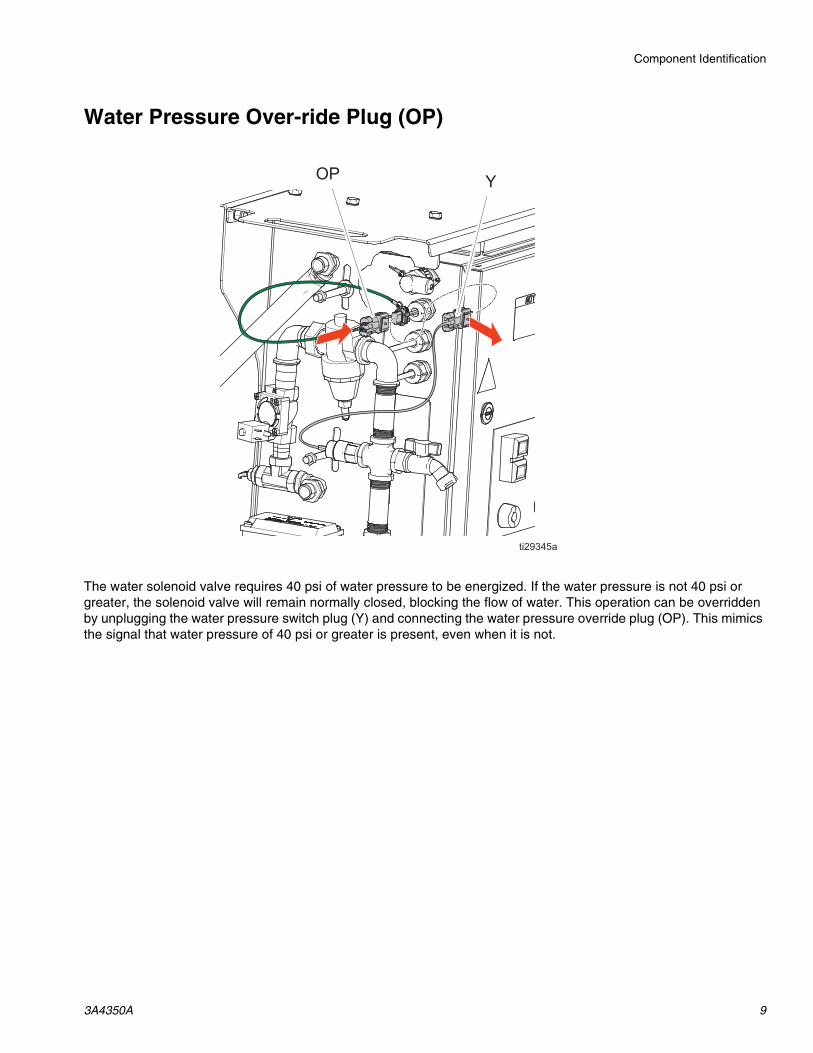
Water Pressure Over-ride Plug (OP)
The water solenoid valve requires 40 psi of water pressure to be energized. If the water pressure is not 40 psi or greater, the solenoid valve will remain normally closed, blocking the flow of water. This operation can be overridden by unplugging the water pressure switch plug (Y) and connecting the water pressure override plug (OP). This mimics the signal that water pressure of 40 psi or greater is present, even when it is not.

Setup
10 3A4350A
Setup
1. Make sure the wedge retainers (K) are secure on the motor side. Make sure both flange faces are paired with their matching counterpart.
2. Verify the flat end of the feed screw (D) is engaged with the motor shaft adapter (MS).
3. Make sure the wedge retainers (K) are secure on the mixing tube (C) side. Make sure both flange faces are paired with their matching counterpart. The mixing shaft (B) should be engaged with the feed screw (D).
4. Make sure the wedge retainers (K) are secure on the mixing tube discharge nozzle (A) side. Make sure both flange faces are paired with their match-ing counterpart.
5. CM-40: Secure the hopper grate (G) onto the top of the hopper (H).
CM-40 Silo: Mount the mixer to the appropriate sized silo using the provided butterfly seal and fas-teners. The butterfly seal should be assembled between the butterfly valve (Z) and silo.
NOTE: See Butterfly Valve Mounting Pattern, page 16, for the butterfly valve diameter and mount-ing pattern.
6. Position the mixer over the pump hopper. The mixer should be on a horizontal surface so it is secure and stable.
7. Connect the motor cable (F) to the power out con-nector (P).
8. Connect the power cable (M) to the main power in connector (N).
9. Connect to the appropriate power source.
Electrical Components
Power Cable Color Code
Grounding
The system is grounded through the power cord.
To help prevent injury from moving parts, do not operate with the grate (J) removed.
Power Cable MTA158 (for systems 25M080, 25M081, 25M085, 25M086)
Line 1 BlackLine 2 WhiteGround GreenPower Cable MTA380 (for systems 25M082, 25M087)Line 1 BlackLine 2 WhiteLine 3 RedGround Green
The equipment must be grounded to reduce the risk of static sparking and electric shock. Electric or static sparking can cause fumes to ignite or explode. Improper grounding can cause electric shock. Grounding provides an escape wire for the electric current.

Operation
3A4350A 11
Operation
Start Up
1. Attach a water feed hose to the water pump system inlet (LB).
NOTE: The connection is a 3/4 in. female garden hose type fitting.
NOTE: The water feed must be able to supply water pressure of 40 psi or greater or else the mixer will not operate in the forward direction. A pressure switch that controls the forward direction operation of the mixer activates at 40 psi, allowing for forward operation. If water pressure is below 40 psi and the mixer must be operated in the forward direction, the pressure switch can be bypassed by connecting the water pressure bypass plug.
2. Turn the power disconnect switch (Q) to ON.
3. Turn the water pump switch (W) to ON.
4. Press and hold the water prime button (U).
5. Set the water flow meter (LH) to 3 gpm, then release the water prime button (U).
6. Press the START button (R) to run the mixing shaft.
NOTE: A scraping noise is normal as the mixing tines run close to the inside of the hopper.
7. Verify water is flowing through the mixing tube (C) and out the mixing tube discharge nozzle (A).
8. Hold the motor direction switch (T) in the REV posi-tion for several seconds. Verify the mixing shaft is turning in the opposite direction and water has stopped flowing out of the mixing tube discharge nozzle (A).
NOTE: When running in reverse, the water solenoid valve (LF) is not energized and is closed. This stops water from being fed into the mixer.
NOTE: The motor direction switch (T) is normally in the FWD position. The switch must be held in the REV position to reverse the pump direction. The switch will return to the FWD position when it is released.
9. Press the STOP button (R) to stop the motor.
10. Turn the water pump switch (W) to OFF.ON
OFF
VFDFAULTWHEN
LIT
WATER PRIME
SPEED SELECTOR
WATER PSI
WATER PSIFWR REV1
23
WATER PUMPOFF ON
NOTICE
Do not allow the water pump to operate with no flow for more than five minutes. The water pump can become overheated and become damaged.

Operation
12 3A4350A
Mixing and Dispensing Material
1. Add dry material:
CM-40: Set a bag of material on the center of the hopper grate (G) so the teeth are in the middle of the bag. Twist the bag 15 degrees in both directions to rip open, and lift both ends of the bag so the dry material falls into the hopper. Dispose of bag.
CM-40 Silo: Fill the silo with material. Open the silo butterfly valve (Z) slowly to allow material to drop into the feed section of the mixer.
NOTE: During operation, keep the hopper filled with dry material. Do not allow the level to drop below the top of the feed screw (D) or the output material con-sistency will change.
2. With the main power disconnect switch (Q) set to OFF, remove the mixing tube discharge nozzle (A), mixing shaft (B), and mixing tube (C).
3. Turn the power disconnect switch (Q) to ON.
Avoid contact with the discharge nozzle (A) and feed liner (FL) while mixing and dispensing material. These parts can pull in, crush, cut or amputate fingers and other body parts.
Adding material to the hopper generates clouds of dust, and exposes the user to the sharp teeth on the hopper grate. Always wear protective equip-ment when adding material to the hopper.
NOTICE
When removing a wedge retainer (K), hit the under-side with a rubber mallet. Do not hit the pointed end of the wedge retainer. The end of the wedge can become damaged or bent, and no longer fit through the retaining slot.
ON
OFF
VFDFAULTWHEN
LIT
WATER PRIME
SPEED SELECTOR
WATER PSI
WATER PSIFWR REV1
23
WATER PUMPOFF ON

Operation
3A4350A 13
4. Press the START button (R) and verify there is material output from the feed liner (FL). Place a bucket under the feed liner (FL) to catch any dry material output.
5. Adjust the speed selector knob (S) to your desired output level and press the STOP button (R).
6. Turn the power disconnect switch (Q) to OFF.
7. Reattach the mixing tube discharge nozzle (A), mix-ing shaft (B), and mixing tube (C).
8. Turn the power disconnect switch (Q) to ON.
9. Turn the water pump switch (W) to ON and press the START button (R).
10. Observe the material output and adjust the water flow meter (LH) until your desired material consis-tency is achieved.

Operation
14 3A4350A
Clean Out
When finished mixing and dispensing material or taking an extended break, the mixer should be emptied and cleaned thoroughly so material does not cure and harden in the system.
1. Continue to mix and dispense material until no dry material remains.
CM-40: Do not add any more bags of dry material to the hopper. Run the mixer until the hopper (H) is empty and only clear water exits the mixing tube discharge nozzle (A).
CM-40 Silo: Close the silo butterfly valve (SV) and run the mixer until only clear water exits the mixing tube discharge nozzle (A).
2. Press the STOP button (R) and turn the water pump switch (W) to OFF.
3. Turn the power disconnect switch (Q) to OFF.
4. Clean mixing tube assembly:
a. Remove the mixing tube discharge nozzle (A), mixing shaft (B), and mixing tube (C).
b. Thoroughly clean the removed parts with water. A water hose can be attached to the water fau-cet valve (LD) to spray down the mixing parts.
NOTE: The mixing tube can be removed from its steel support sleeve for easier and more thorough cleaning.
Avoid contact with the discharge nozzle (A) and feed liner (FL) during clean out. These parts can pull in, crush, cut or amputate fingers and other body parts.
ON
OFF
VFDFAULTWHEN
LIT
WATER PRIME
SPEED SELECTOR
WATER PSI
WATER PSIFWR REV1
23
WATER PUMPOFF ON
Operation
3A4350A 15
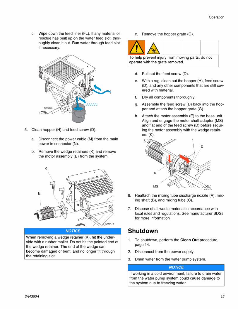
c. Wipe down the feed liner (FL). If any material or residue has built up on the water feed slot, thor-oughly clean it out. Run water through feed slot if necessary.
5. Clean hopper (H) and feed screw (D):
a. Disconnect the power cable (M) from the main power in connector (N).
b. Remove the wedge retainers (K) and remove the motor assembly (E) from the system.
c. Remove the hopper grate (G).
d. Pull out the feed screw (D).
e. With a rag, clean out the hopper (H), feed screw (D), and any other components that are still cov-ered with material.
f. Dry all components thoroughly.
g. Assemble the feed screw (D) back into the hop-per and attach the hopper grate (G).
h. Attach the motor assembly (E) to the base unit. Align and engage the motor shaft adapter (MS) and flat end of the feed screw (D) before secur-ing the motor assembly with the wedge retain-ers (K).
6. Reattach the mixing tube discharge nozzle (A), mix-ing shaft (B), and mixing tube (C).
7. Dispose of all waste material in accordance with local rules and regulations. See manufacturer SDSs for more information
Shutdown1. To shutdown, perform the Clean Out procedure,
page 14.
2. Disconnect from the power supply.
3. Drain water from the water pump system.
NOTICE
When removing a wedge retainer (K), hit the under-side with a rubber mallet. Do not hit the pointed end of the wedge retainer. The end of the wedge can become damaged or bent, and no longer fit through the retaining slot.
To help prevent injury from moving parts, do not operate with the grate removed.
NOTICE
If working in a cold environment, failure to drain water from the water pump system could cause damage to the system due to freezing water.
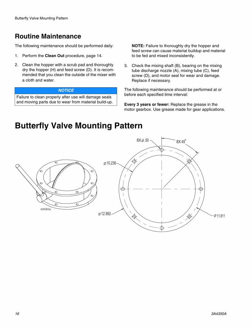
Butterfly Valve Mounting Pattern
16 3A4350A
Routine MaintenanceThe following maintenance should be performed daily:
1. Perform the Clean Out procedure, page 14.
2. Clean the hopper with a scrub pad and thoroughly dry the hopper (H) and feed screw (D). It is recom-mended that you clean the outside of the mixer with a cloth and water.
NOTE: Failure to thoroughly dry the hopper and feed screw can cause material buildup and material to be fed and mixed inconsistently.
3. Check the mixing shaft (B), bearing on the mixing tube discharge nozzle (A), mixing tube (C), feed screw (D), and motor seal for wear and damage. Replace if necessary.
The following maintenance should be performed at or before each specified time interval:
Every 3 years or fewer: Replace the grease in the motor gearbox. Use grease made for gear applications.
Butterfly Valve Mounting Pattern
NOTICE
Failure to clean properly after use will damage seals and moving parts due to wear from material build-up.

Technical Specifications
3A4350A 17
Technical Specifications
ToughTek CM-40 Continuous MixersUS Metric
Maximum Motor Speed 314 rpm
Wetted Parts Tool steel, painted steel, plated steel, PORON®
Water Pump Inlet Feed Pressure Requirements
Minimum Pressure 40 psi 0.28, 2.8 barMaximum Pressure 70 psi 0.48 MPa, 4.8 barHopper Capacity
CM-40 16 gallon 60.6 litersWeight (empty)
CM-40 460 lb 209 kgCM-40 Silo 440 lb 200 kgNoise Level (measured at 3.1 ft)Sound Pressure 91 dBa
Operating Ambient TemperatureTemperature 32° F to 120° F 0° C to 49° C
Power Requirements
Part Number VoltageMinimum Circuit
Breaker SizePhase Frequency
25M080 200-240 VAC 30 A 1 Phase 50 Hz
25M081 200-240 VAC 30 A 1 Phase 60 Hz25M082 200-240 VAC 25 A 3 Phase 50 Hz25M085 200-240 VAC 30 A 1 Phase 50 Hz
25M086 200-240 VAC 30 A 1 Phase 60 Hz25M087 200-240 VAC 25 A 3 Phase 50 Hz

All written and visual data contained in this document reflects the latest product information available at the time of publication. Graco reserves the right to make changes at any time without notice.
Original instructions. This manual contains English. MM 3A3650Graco Headquarters: Minneapolis
International Offices: Belgium, China, Japan, Korea
GRACO INC. AND SUBSIDIARIES • P.O. BOX 1441 • MINNEAPOLIS MN 55440-1441 • USACopyright 2016, Graco Inc. All Graco manufacturing locations are registered to ISO 9001.
www.graco.comRevision A, July 2016
Graco Standard WarrantyGraco warrants all equipment referenced in this document which is manufactured by Graco and bearing its name to be free from defects in material and workmanship on the date of sale to the original purchaser for use. With the exception of any special, extended, or limited warranty published by Graco, Graco will, for a period of twelve months from the date of sale, repair or replace any part of the equipment determined by Graco to be defective. This warranty applies only when the equipment is installed, operated and maintained in accordance with Graco’s written recommendations.
This warranty does not cover, and Graco shall not be liable for general wear and tear, or any malfunction, damage or wear caused by faulty installation, misapplication, abrasion, corrosion, inadequate or improper maintenance, negligence, accident, tampering, or substitution of non-Graco component parts. Nor shall Graco be liable for malfunction, damage or wear caused by the incompatibility of Graco equipment with structures, accessories, equipment or materials not supplied by Graco, or the improper design, manufacture, installation, operation or maintenance of structures, accessories, equipment or materials not supplied by Graco.
This warranty is conditioned upon the prepaid return of the equipment claimed to be defective to an authorized Graco distributor for verification of the claimed defect. If the claimed defect is verified, Graco will repair or replace free of charge any defective parts. The equipment will be returned to the original purchaser transportation prepaid. If inspection of the equipment does not disclose any defect in material or workmanship, repairs will be made at a reasonable charge, which charges may include the costs of parts, labor, and transportation.
THIS WARRANTY IS EXCLUSIVE, AND IS IN LIEU OF ANY OTHER WARRANTIES, EXPRESS OR IMPLIED, INCLUDING BUT NOT LIMITED TO WARRANTY OF MERCHANTABILITY OR WARRANTY OF FITNESS FOR A PARTICULAR PURPOSE.
Graco’s sole obligation and buyer’s sole remedy for any breach of warranty shall be as set forth above. The buyer agrees that no other remedy (including, but not limited to, incidental or consequential damages for lost profits, lost sales, injury to person or property, or any other incidental or consequential loss) shall be available. Any action for breach of warranty must be brought within two (2) years of the date of sale.
GRACO MAKES NO WARRANTY, AND DISCLAIMS ALL IMPLIED WARRANTIES OF MERCHANTABILITY AND FITNESS FOR A PARTICULAR PURPOSE, IN CONNECTION WITH ACCESSORIES, EQUIPMENT, MATERIALS OR COMPONENTS SOLD BUT NOT MANUFACTURED BY GRACO. These items sold, but not manufactured by Graco (such as electric motors, switches, hose, etc.), are subject to the warranty, if any, of their manufacturer. Graco will provide purchaser with reasonable assistance in making any claim for breach of these warranties.
In no event will Graco be liable for indirect, incidental, special or consequential damages resulting from Graco supplying equipment hereunder, or the furnishing, performance, or use of any products or other goods sold hereto, whether due to a breach of contract, breach of warranty, the negligence of Graco, or otherwise.
FOR GRACO CANADA CUSTOMERSThe Parties acknowledge that they have required that the present document, as well as all documents, notices and legal proceedings entered into, given or instituted pursuant hereto or relating directly or indirectly hereto, be drawn up in English. Les parties reconnaissent avoir convenu que la rédaction du présente document sera en Anglais, ainsi que tous documents, avis et procédures judiciaires exécutés, donnés ou intentés, à la suite de ou en rapport, directement ou indirectement, avec les procédures concernées.
Graco InformationFor the latest information about Graco products, visit www.graco.com.
For patent information, see www.graco.com/patents.
TO PLACE AN ORDER, contact your Graco distributor or call to identify the nearest distributor.Phone: 612-623-6921 or Toll Free: 1-800-328-0211 Fax: 612-378-3505