Embed Size (px)
Citation preview
TOOLS FOR ACTIVE CONTROL SISTEM DESIGN
William M. Adams, Jr., Sherwood H. Tiffany, and Jerry R. Newsom
NASA Langley Research Center Hampton, Virginia
First Annual NASA AirSraft Controls Workshop NASA Langley Research Center
Hampton, Virginia October 25-27, 1983
263
https://ntrs.nasa.gov/search.jsp?R=19840012514 2019-04-28T13:44:01+00:00Z
The objective of the research reported here is to develop efficient control law analysis and design tools which properly account for the interaction of flexible structures, unsteady aerodynamics and active controls. The next two figures indicate how such tools can be employed to incorporate active controls into the aircraft design process.
DEVELOPMENT. APPLICATION. VALIDATION AND DOCUMENTATION OF EFFICIENT MULTIDISCIPLINARY COMPUTER PROGRAMS FOR ANALYSIS AND DESIGN OF ACTIVE CONTROL LAWS
264
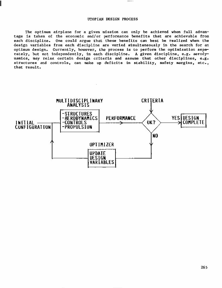
UTOPIAN DESIGN PROCESS
The optimum airplane for a given mission can only be achieved when full advan- tage is taken of the economic and/or performance benefits that are achievable from each discipline. One could argue that these benefits can best be realized when the design variables from each discipline are varied simultaneously in the search for an optimum design. Currently, however, the process is to perform the optimization sepa- rately, but not independently, in each discipline. A given discipline, e.g. aerody- namics, may relax certain design criteria and assume that other disciplines, e.g. structures and controls, can make up deficits in stability, safety margins, etc., that result.
INITIAL - CUNFIGURATIOI
MULTIDISCIPLINAKY ANALYSIS
CR
-STRUCTURES -AERODYNAMICS -CONTROLS -PROPULSION
I ERIA T
] PEKFO;hANCE 6 YEq-iiii-&
OPTIMIZER
KKl VARIABLES
NO
\I
I
265
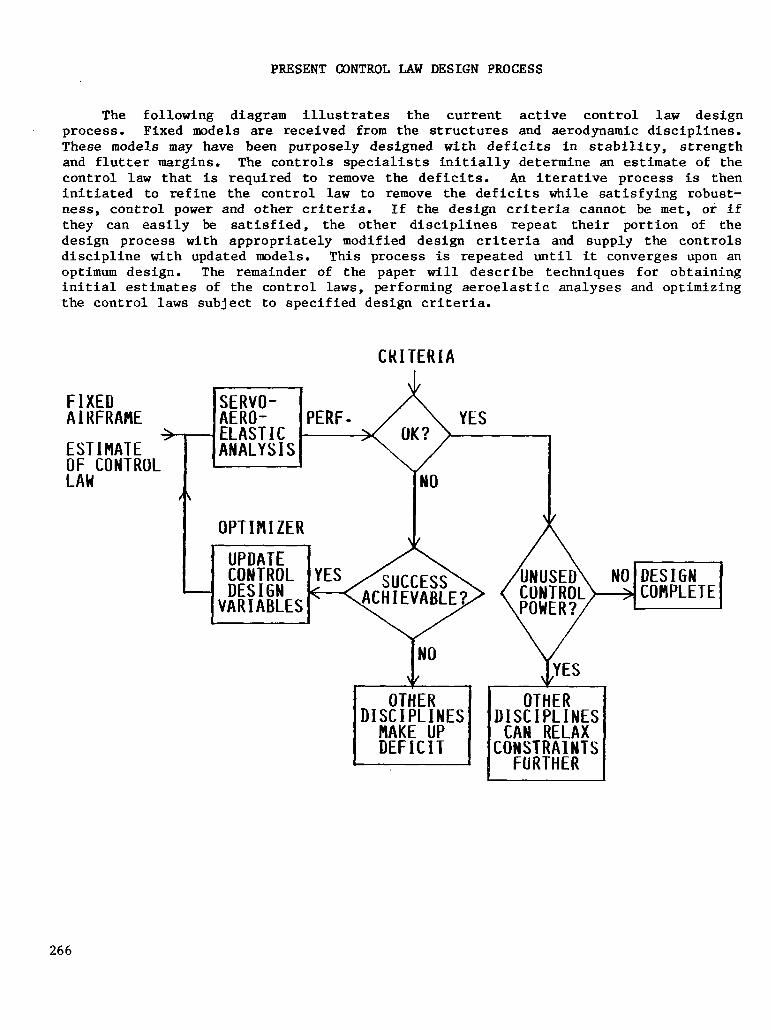
PRESENT CONTROL LAW DESIGN PROCESS
The following diagram illustrates the current active control law design process. Fixed models are received from the structures and aerodynamic disciplines. These models may have been purposely designed with deficits in stability, strength and flutter margins. The controls specialists initially determine an estimate of the control law that is required to remove the deficits. An iterative process is then initiated to refine the control law to remove the deficits while satisfying robust- ness, control power and other criteria. If the design criteria cannot be met, or if they can easily be satisfied, the other disciplines repeat their portion of the design process with appropriately modified design criteria and supply the controls discipline with updated models. This process is repeated until it converges upon an optimum design. The remainder of the paper will describe techniques for obtaining initial estimates of the control laws, performing aeroelastic analyses and optimizing the control laws subject to specified design criteria.
CRITERIA
FIXED AlRFRAfiE \ / tLASl IL ESTIMATE ANALYSIS OF CONTROL
YES
fN0 V
266
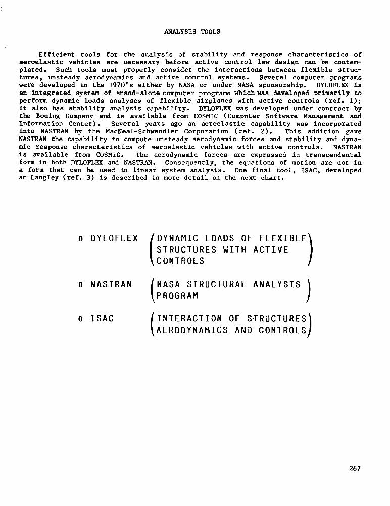
ANALYSIS TOOLS
Efficient tools for the analysis of stability and response characteristics of aeroelastic vehicles are necessary before active control law design can be contem- plated. Such tools must properly consider the interactions between flexible struc- tures, unsteady aerodynamics and active control systems. Several computer programs were developed in the 1970's either by NASA or under NASA sponsorship. DYLOFLEX is an integrated system of stand-alone computer programs whichwas developed primarily to perform dynamic loads analyses of flexible airplanes with active controls (ref. 1); it also has stability analysis capability. DYLOFLEX was developed under contract by the Boeing Company and is available from COSMIC (Computer Software Management and Information Center). Several years ago an aeroelastic capability was incorporated into NASTBAN by the MacNeal-Schwendler Corporation (ref. 2). This addition gave NASTRAN the capability to compute unsteady aerodynamic forces and stability and dyna- mic response characteristics of aeroelastic vehicles with active controls. NASTRAN is available from COSMIC. The aerodynamic forces are expressed in transcendental form in both DYLOFLEX and NASTBAN. Consequently, the equations of motion are not in a form that can be used in linear system analysis. One final tool, ISAC, developed at Langley (ref. 3) is described in more detail on the next chart.
o DYLOFLEX DYNAMIC LOADS OF FLEXIBLE STRUCTURES WITH ACTIVE CONTROLS
o NASTRAN NASA STRUCTURAL ANALYSIS PROGRAM
o ISAC INTERACTION OF STRUCTURES AERODYNAMICS AND CONTROLS
267
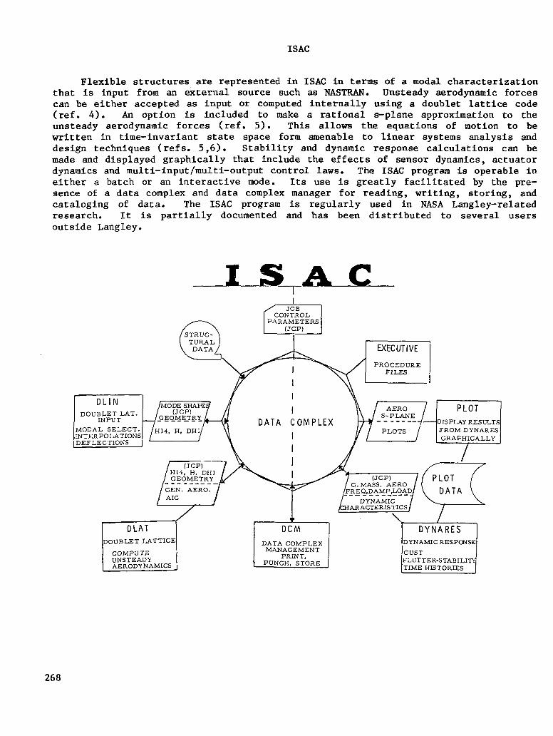
ISAC
Flexible structures are represented in ISAC in terms of a modal characterization that is input from an external source such as NASTRAN. Unsteady aerodynamic forces can be either accepted as input or computed internally using a doublet lattice code (ref. 4). An option is included to make a rational s-plane approximation to the unsteady aerodynamic forces (ref. 5). This allows the equations of motion to be written in time-invariant state space form amenable to linear systems analysis and design techniques (refs. 5,6). Stability and dynamic response calculations can be made and displayed graphically that include the effects of sensor dynamics, actuator dynamics and multi-input/multi-output control laws. The ISAC program is operable in either a batch or an interactive mode. Its use is greatly facilitated by the pre- sence of a data complex and data complex manager for reading, writing, storing, and cataloging of data. The ISAC program is regularly used in NASA Langley-related research. It is partially documented and has been distributed to several users outside Langley.
I I ,Icm\ MODE SHAFE
I
MODAL SELECT. INTERPOLATIONS DEFLECTIONS J
268
DAST ARW-2 PROJECT SUPPORT
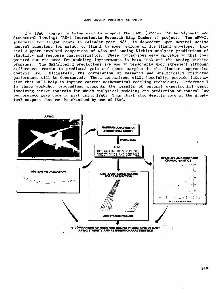
The ISAC program is being used to support the DAST (Drones for Aerodynamic and Structural Testing) ARW-2 (Aeroelastic Research Wing Number 2) project. The ARW-2, scheduled for flight tests in calendar year 1985, is dependent upon several active control functions for safety of flight in some regions of its flight envelope. Ini- tial support involved comparison of NASA and Boeing Wichita analytic predictions of stability and response characteristics. These comparisons were valuable in that they pointed out the need for modeling improvements in both ISAC and the Boeing Wichita programs. The NASA/Boeing predictions are now in reasonably good agreement although differences remain in predicted gain and phase margins in the flutter suppression control law. Ultimately, the correlation of measured and analytically predicted performance will be documented. These comparisons will, hopefully, provide informa- tion that will help to improve current mathematical modeling techniques. Reference 7 in these workshop proceedings presents the results of several experimental tests involving active controls for which analytical modeling and prediction of control law performance were done in part using ISAC. This chart also depicts some of the graph- ical outputs that can be obtained by use of ISAC.
0 COMPARBON OF NASA AND BDEINQ PREWCTIOM OF DAST ANW-2 STAEJUTY AND RES#)IYSE CHhRACEmSlWS
269
DESIGN TOOLS
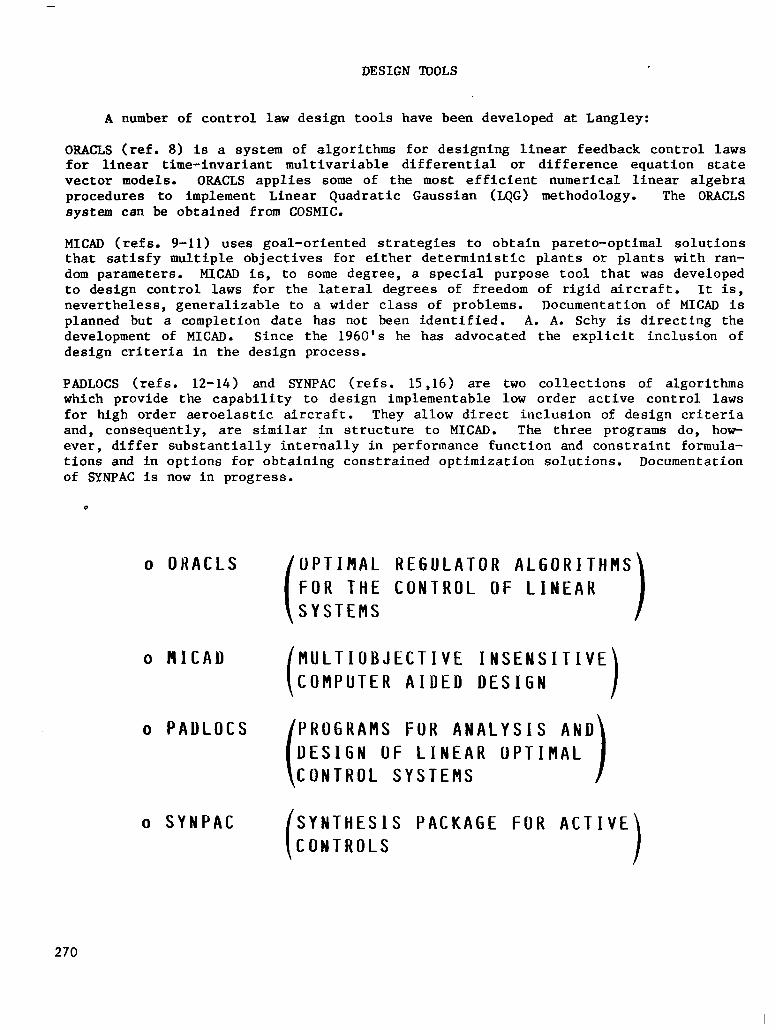
A number of control law design tools have been developed at Langley:
ORACLS (ref. 8) is a system of algorithms for designing linear feedback control laws for linear time-invariant multivariable differential or difference equation state vector models. ORACLS applies some of the most efficient numerical linear algebra procedures to implement Linear Quadratic Gaussian (LQG) methodology. The ORACLS system can be obtained from COSMIC.
MICAD (refs. 9-11) uses goal-oriented strategies to obtain pareto-optimal solutions that satisfy multiple objectives for either deterministic plants or plants with ran- dom parameters. MICAD is, to some degree, a special purpose tool that was developed to design control laws for the lateral degrees of freedom of rigid aircraft. It is, nevertheless, generalizable to a wider class of problems. Documentation of MICAD is planned but a completion date has not been identified. A. A. Schy is directing the development of MICAD. Since the 1960's he has advocated the explicit inclusion of design criteria in the design process.
PADLOCS (refs. 12-14) and SYNPAC (refs. 15,16) are two collections of algorithms which provide the capability to design implementable low order active control laws for high order aeroelastic aircraft. They allow direct inclusion of design criteria and, consequently, are similar in structure to MICAD. The three programs do, hop ever, differ substantially internally in performance function and constraint formula- tions and in options for obtaining constrained optimization solutions. Documentation of SYNPAC is now in progress.
o ORACLS UPTIRAL REGULATOR ALGORITHMS FOR THE CONTROL OF LINEAR SYSTEMS
o HICAD MULTIOBJECTIVE INSENSITIVE COMPUTER AIDED DESIGN
o PADLOCS PROGRAMS FUR ANALYSIS AND DESIGN OF LINEAR OPTIMAL CONTROL SYSTEMS
o SYNPAC SYNTHESIS PACKAGE FOR ACTIVE CONTROLS
270
ISAC/ORACLS/SYNPAC INTERFACE
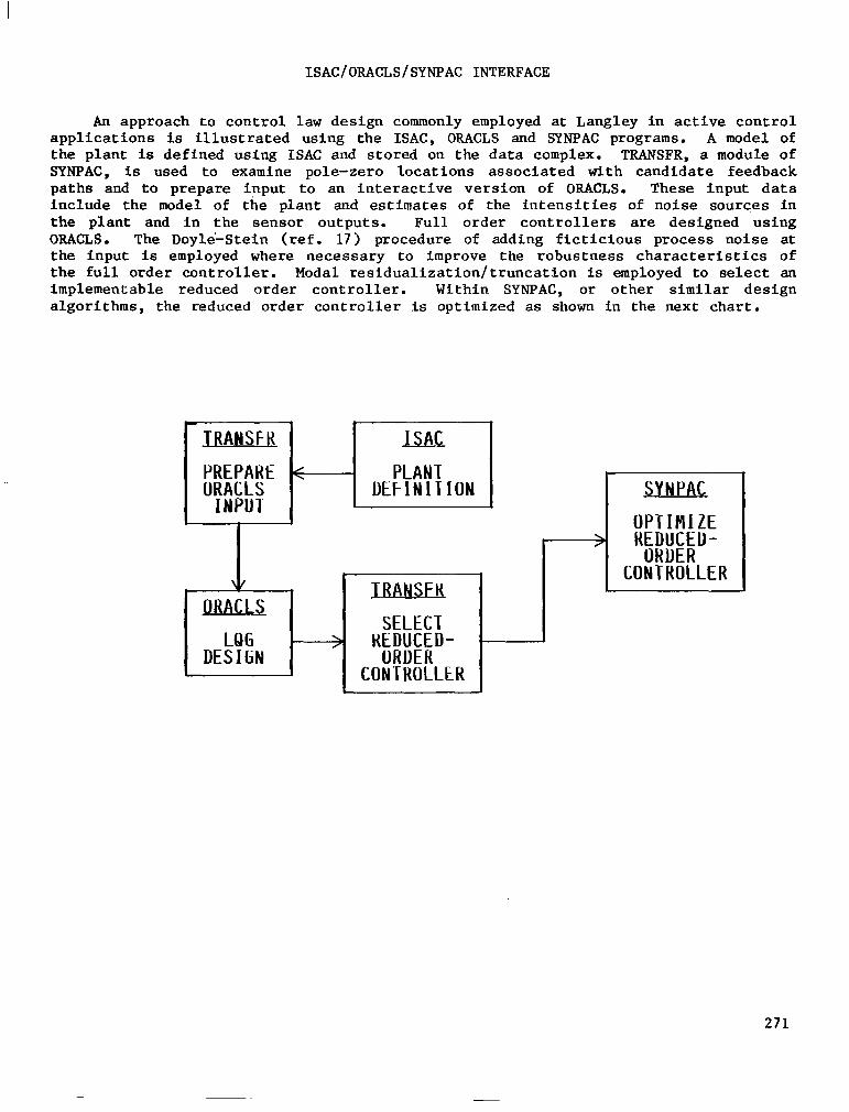
An approach to control law design commonly employed at Langley in active control applications is illustrated using the ISAC, ORACLS and SYNPAC programs. A model of the plant is defined using ISAC and stored on the data complex. TRANSFR, a module of SYNPAC, is used to examine pole-zero locations associated with candidate feedback paths and to prepare input to an interactive version of ORACLS. These input data include the model of the plant and estimates of the intensities of noise sources in the plant and in the sensor outputs. Full order controllers are designed using ORACLS. The Doyle-Stein (ref. 17) procedure of adding fictitious process noise at the input is employed where necessary to improve the robustness characteristics of the full order controller. Modal residualization/truncation is employed to select an implementable reduced order controller. Within SYNPAC, or other similar design algorithms, the reduced order controller is optimized as shown in the next chart.
LQG DESIGN
SELECT HHW&D-
CONTROLLER
271
SYNTHESIS PACKAGE FOR ACTIVE CONTROLS
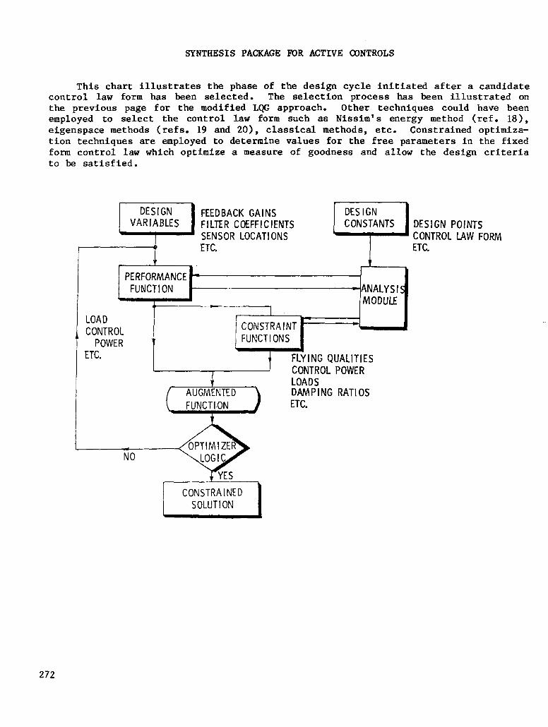
This chart illustrates the phase of the design cycle initiated after a candidate control law form has been selected. The selection process has been illustrated on the previous page for the modified LQG approach. Other techniques could have been employed to select the control law form such as Nissim's energy method (ref. 18), eigenspace methods (refs. 19 and 20), classical methods, etc. Constrained optimiza- tion techniques are employed to determine values for the free parameters in the fixed form control law which optimize a measure of goodness and allow the design criteria to be satisfied.
DESIGN FEEDBACK GAINS DESIGN VARIABLES FILTER COEFFICIENTS CONSTANTS DESIGN POINTS
\ SENSOR LOCATIONS < CONTROL LAW FORM y ETC. ETC. Y 1
PERFORMANCE - FUNCTION -ANALYSl
t MODULE
--7 LOAD I
CONTROL [ ”
POWER -- t l-c. 7
CONTROL POWER LOADS DAMPING RATIOS ETC.
272
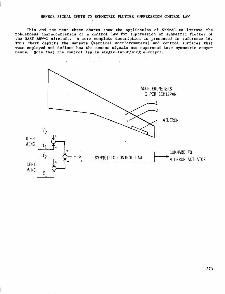
SENSOR SIGNAL IPUTS TO SYMMETRIC FLUTTER SUPPRESSION CONTROL LAW
This and the next three charts show the application of SYNPAC to improve the robustness characteristics of a control law for suppression of symmetric flutter of the DAST ARW-2 aircraft. A more complete description is presented in reference 16. This chart depicts the. sensors (vertical accelerometers) and control surfaces that were employed and defines how the sensor signals are separated into symmetric compo- nents. Note that the control law is single-input/single-output.
ACCELEROMETERS 2 PER SEMISPAN
AILERON
RIGHT WING
COMMAND > SYMMETRIC CONTROL LAW 'AILERON
TO
ACTUATOR
273
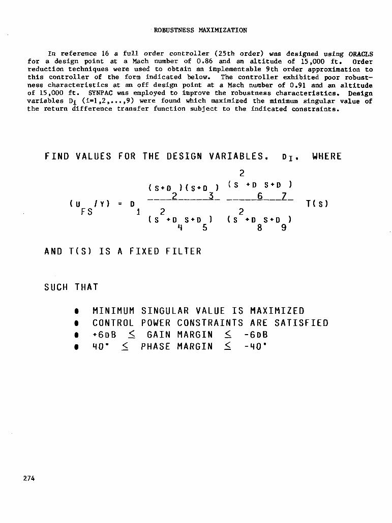
ROBUSTNESS MAXIMIZATION
In reference 16 a full order controller (25th order) was designed using ORACl,S for a design point at a Mach number of 0.86 and an altitude of 15,000 ft. Order reduction techniques were used to obtain an implementable 9th order approximation to this controller of the form indicated below. The controller exhibited poor robust- ness characteristics at an off design point at a Mach number of 0.91 and an altitude of 15,000 ft. SYNPAC was employed to improve the robustness characteristics. Design variables Di (i=1,2 ,...,9) were found which maximized the minimum singular value of the return difference transfer function subject to the indicated constraints.
FIND VALUES FOR THE DESIGN VARIABLES. DI.
2
( s+D2) h+Dj) ( s +D6S+D7)
hl /Y) = D ---------me- ---_---____
FS 12 2
( s +D4s+D51 (s +D8S+D9)
AND T(S) IS A FIXED FILTER
SUCH THAT
WHERE
T(s)
0 MINIMUM SINGULAR VALUE IS MAXIMIZED 0 CONTROL POWER CONSTRAINTS ARE SATISFIED 0 +6DB < GAIN MARGIN < -6DB 0 40' s PHASE MARGIN s -40'
274
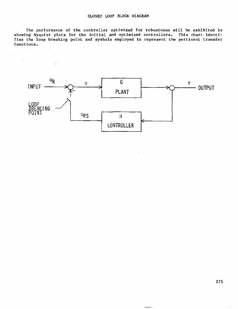
CLOSED MOP BLOCK DIAGRAM
The performance of the controller optimized for robustness will be exhibited by showing Nyquist plots for the initial and optimized controllers. This chart identi- fies the loop breaking point and symbols employed to represent the pertinent transfer functions.
I I
INPUT >o ' OUTPUT UR ?- " 1:;
275
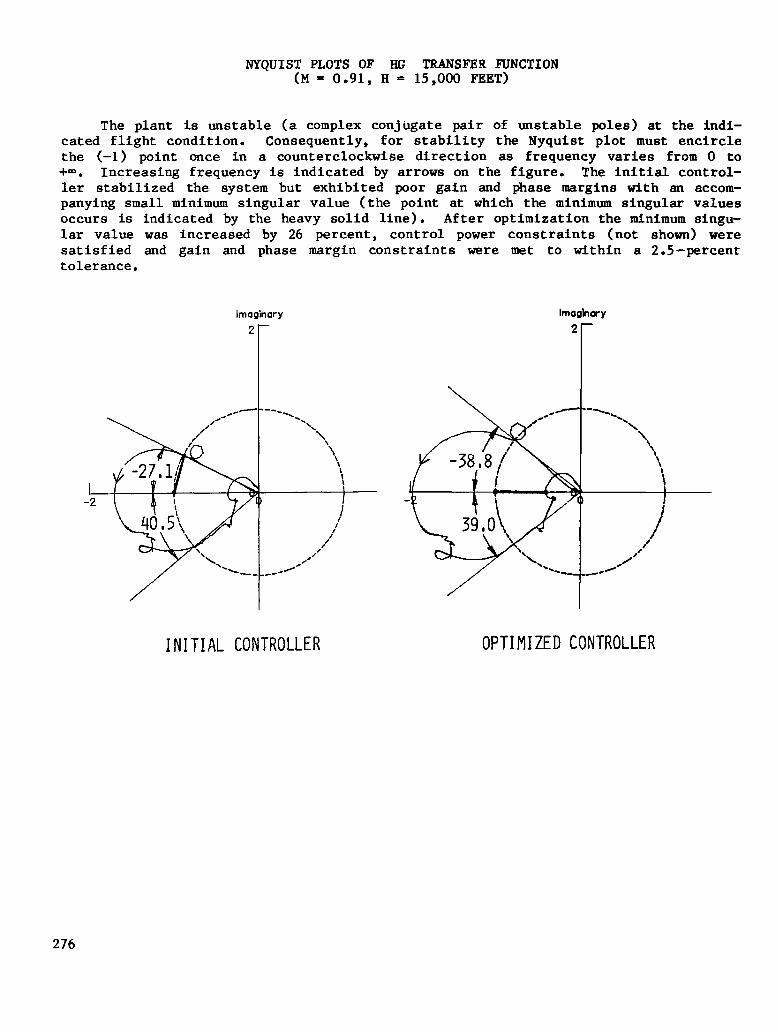
NYQUIST PLOTS OF HG TRANSFEH FUNCTION (M = 0.91, H = 15,000 FEET)
The plant is unstable (a complex conjugate pair of unstable poles) at the indi- cated flight condition. Consequently, for stability the Nyquist plot must encircle the (-1) point once' in a counterclockwise direction as frequency varies from 0 to +-co. Increasing frequency is indicated by arrows on the figure. The initial control- ler stabilized the system but exhibited poor gain and phase margins with an accom- panying small minimum singular value (the point at which the minimum singular values occurs is indicated by the heavy solid line). After optimization the minimum singu- lar value was increased by 26 percent, control power constraints (not shown) were satisfied and gain and phase margin constraints ware met to within a 2.5-percent tolerance.
lmoginary
INITIAL CONTROLLER
Imoghmy
OPTIMIZED CONTROLLER
276
CONCLUDING REMARK3
Several tools applicable to analysis and design of control laws for aeroelastic vehicles have been identified. DYLOFLEX and NASTRAN are available from COSMIC. ISAC, developed primarily for in-house research, is only partially documented and would require substantial modification for use on a computer complex differing from the one at Langley. It has, nevertheless, been distributed to several off-site users. ORACLS is the only design tool that is sufficiently well documented for dis- tribution. Linear potential flow aerodynamic theory is employed in computing aerody- namic forces. Consequently, the modeling accuracy becomes doubtful at analysis and design points approaching the transonic region. Improvement is needed in the aerody- namic modeling.
l ANALYSlS AND DESIGN TOOLS IDENTIFIED
l CKITERIA EXPLICIlLY INCLUUED IN DESIGN PROCEUUHE
l CONCERN ABOUT UNMODELED NONLINEAR AERODYNAMIC EFFECTS
l DOCUMENTATION OF ANALYSIS AND DESIGN TOOLS IS UNDERWAY
277
REFERENCES
1. Perry, B. III; Kroll, R. I.; Miller, R. D.; and Goetz, R. C.: DYLOFLEX: A Computer Program for Flexible Aircraft Flight Dynamic Loads Analysis with Active Controls. Journal of Aircraft, Vol. 17, No. 4, April 1980, pp. 275-282.
2. Harder, Robert L.; MacNeal, Richard H.; and Rodden, William P.: A Design Study for the Incorporation of Aeroelastic Capability into NASTRAN. NASA CR 111918, May 1971.
3. Peele, Ellwood L.; and Adams, William M., Jr.: A Digital Program for Calculat- ing the Interaction Between Flexible Structures, Unsteady Aerodynamics, and Active Controls. NASA TM 80040, January 1979.
4. Albano, E.; and Rodden, W. P.: A Doublet Lattice Method for Calculating Lift Distributions on OscilLating Surfaces in Subsonic Flows. AIAA Journal, Vol. 7, No. 2, February 1969, pp. 279-285.
5. Roger, Kenneth L.: Airplane Math Modeling Methods for Active Control Design. AGARD CR 228, August 1977.
6. Mahesh, J. K.; Stone, C. R.; Garrard, W. L.; and Hausman, P. D.: Active Flutter Control for Flexible Vehicles. NASA CR 159160, November 1979.
7. Newsom, Jerry R.; and Abel, Irving: Experiences With the Design and Implementa- tion of Flutter Suppressiun Systems. NASA Aircraft Controls Research - 1983, NASA CP-2296, 1984, pp. 489-509.
8. Armstrong, Ernest S.: ORACLS - A Design System for Linear Multivariable Control. Marcel Dekker, Inc., c.1980.
9. Schy, Albert A.: Nonlinear Programming in Design of Control Systems with Speci- fied Handling Qualities. Proceedings of 1972 IEEE Conference on Decision and Control and 11th Symposium on Adaptive Processes, December 1972, pp. 272-279.
10. Schy, A. A.; Adams, William M., Jr.; and Johnson, K. G.: Computer-Aided Design of Control Systems to Meet Many Requirements. NATO AGARD ConEerence Proceedings No. 137 on Advances in Control Systems, May 1974, pp 6-l to 6-7.
11. Schy, A. A.; and Giesy, D. P.: Tradeoff Studies in Multiobjective Insensitive Design of Airplane Control Systems. AIAA Paper No. 83-2273, August 1983.
12. Newsom, J. R.: A Method for Obtainiug Practical Flutter Control Laws Using Results of Optimal Control Theory. NASA TP 1471, August 1979.
13. Mukhopadhyay, V.; Newsom, J. R.; and Abel, I.: A Method for Obtaining Reduced Order Control Laws for High Order Systems Using Optimization Techniques. NASA TP 1876, 1981.
14. Newsom, Jerry R.; and Mukhopadhyay, V.: The Use of Singular Value Gradients and Optimization Techniques to Design Robust ControLlers for Multiloop Systems. AIAA Paper No. 83-2191, August 1983.
278
15. Adams, William M., Jr.: and Tiffany, Sherwood H.: Control Law Design to Meet Constraints Using SYNPAC--Synthesis Package for Active Controls. NASA TM 83264, January 1982.
16. Adams, William M., Jr.; and Tiffany, Sherwood, H.: Design of a Candidate Flutter Suppression Control Law for DAST ARW-2. AIAA Paper No. 83-2221, August 1983.
17. Doyle, J. C.; and Stein, G.: Robustness with Observers. IEEE Transactions on Automatic Control, Vol. AC-24, No. 4, August 1979, pp. 607-611.
18. Nissim, E.; and Abel, I.: Development and Application of an Optimization Proce- dure for Flutter Suppression Using the Aerodynamic Energy Concept. NASA TP 1137, February 1978.
19. Garrard, William L.; and Liebst, Bradley S.: Active Flutter Suppression Using Eigenspace and Linear Quadratic Design Techniques. AIAA Paper No. 2222, August 1983.
20. Ostroff, A. J.; and Pines, S.: Application of Modal Control to Wing-Flutter Suppression. NASA TP 1983, May 1982.
279