Embed Size (px)
Citation preview
169
APPENDIX A
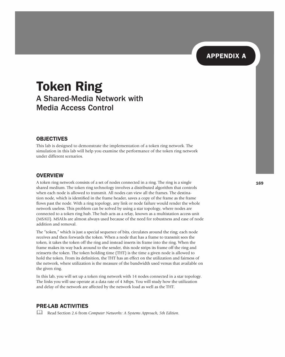
OBJECTIVES This lab is designed to demonstrate the implementation of a token ring network. The simulation in this lab will help you examine the performance of the token ring network under different scenarios.
OVERVIEW A token ring network consists of a set of nodes connected in a ring. The ring is a single shared medium. The token ring technology involves a distributed algorithm that controls when each node is allowed to transmit. All nodes can view all the frames. The destina-tion node, which is identifi ed in the frame header, saves a copy of the frame as the frame fl ows past the node. With a ring topology, any link or node failure would render the whole network useless. This problem can be solved by using a star topology, where nodes are connected to a token ring hub. The hub acts as a relay, known as a multistation access unit (MSAU). MSAUs are almost always used because of the need for robustness and ease of node addition and removal.
The “token,” which is just a special sequence of bits, circulates around the ring; each node receives and then forwards the token. When a node that has a frame to transmit sees the token, it takes the token off the ring and instead inserts its frame into the ring. When the frame makes its way back around to the sender, this node strips its frame off the ring and reinserts the token. The token holding time (THT) is the time a given node is allowed to hold the token. From its defi nition, the THT has an effect on the utilization and fairness of the network, where utilization is the measure of the bandwidth used versus that available on the given ring.
In this lab, you will set up a token ring network with 14 nodes connected in a star topology. The links you will use operate at a data rate of 4 Mbps. You will study how the utilization and delay of the network are affected by the network load as well as the THT.
PRE-LAB ACTIVITIES & Read Section 2.6 from Computer Networks: A Systems Approach , 5th Edition .
Token Ring A Shared-Media Network with Media Access Control
APPENDIX AToken Ring
170
PROCEDURE Create a New Project To create a new project for the token ring network:
1. Start OPNET IT Guru Academic Edition · Choose New from the File menu. 2. Select Project , and click OK · Name the project < your initials>_TokenRing , and the
scenario Balanced · Click OK . 3. In the Startup Wizard: Initial Topology dialog box, make sure that Create Empty Scenario
is selected · Click Next · Choose Offi ce for the Network scale · Click Next three times · Click OK .
4. Close the Object Palette , and Save your project.
Create the Network To create our token ring network:
1. Select Topology · Rapid Confi guration . From the drop-down menu, choose Star and click OK .
2. Click the Select Models button in the Rapid Confi guration dialog box. From the Model List drop-down menu, choose token_ring , and click OK .
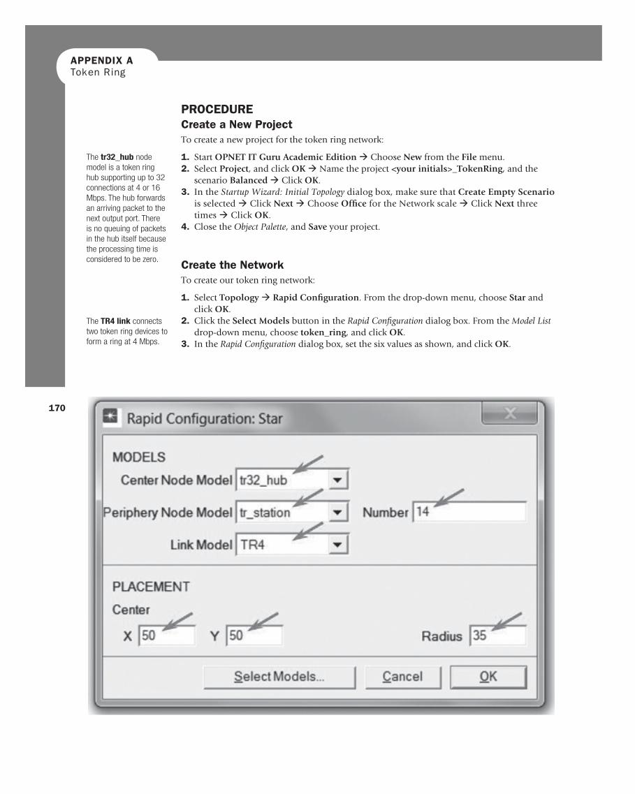
3. In the Rapid Confi guration dialog box, set the six values as shown, and click OK .
The tr32_hub node model is a token ring hub supporting up to 32 connections at 4 or 16 Mbps. The hub forwards an arriving packet to the next output port. There is no queuing of packets in the hub itself because the processing time is considered to be zero.
The TR4 link connects two token ring devices to form a ring at 4 Mbps.
171
ABOELELA 978-0-12-385210-6 00016
APPENDIX A Token Ring
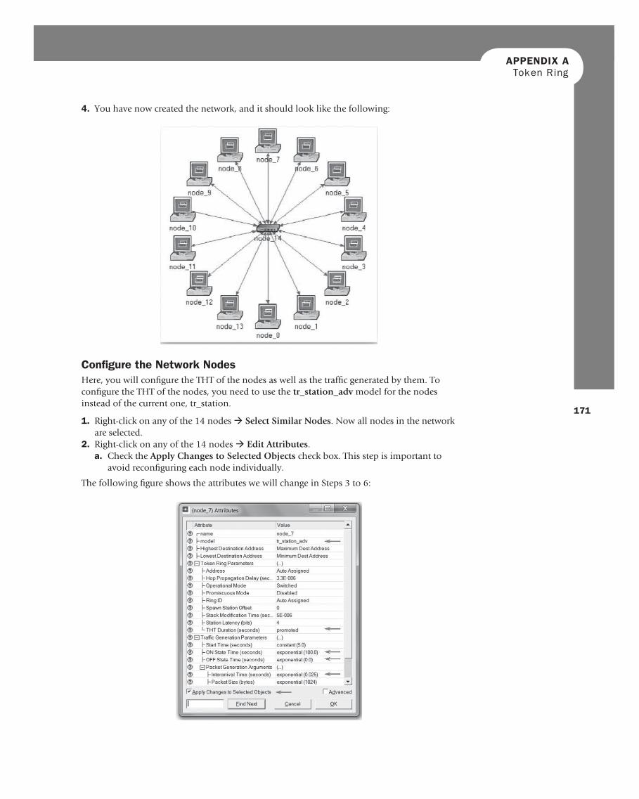
Confi gure the Network Nodes Here, you will confi gure the THT of the nodes as well as the traffi c generated by them. To confi gure the THT of the nodes, you need to use the tr_station_adv model for the nodes instead of the current one, tr_station.
1. Right-click on any of the 14 nodes · Select Similar Nodes . Now all nodes in the network are selected.
2. Right-click on any of the 14 nodes · Edit Attributes . a. Check the Apply Changes to Selected Objects check box. This step is important to
avoid reconfi guring each node individually.
The following fi gure shows the attributes we will change in Steps 3 to 6:
4. You have now created the network, and it should look like the following:
APPENDIX AToken Ring
172
3. Click on the model value: tr_station , and select Edit from the drop-down menu. Now select tr_station_adv from the extended drop-down menu.
4. To test the network under different THT values, you need to “promote” the THT param-eter. This will allow us to assign multiple values to the THT attribute. a. Expand the Token Ring Parameters hierarchy. b. Right-click on the THT Duration attribute · Choose Promote Attribute to Higher
Level. 5. Expand the Traffi c Generation Parameters hierarchy · Assign exponential(100) to the
ON State Time attribute · Assign exponential(0) to the OFF State Time attribute. ( Note: Packets are generated only in the “ON” state.)
6. Expand the Packet Generation Arguments hierarchy · Assign exponential(0.025) to the Interarrival Time attribute.
7. Click OK to return to the Project Editor . 8. Save your project.
Confi gure the Simulation To examine the network performance under different THTs, you need to run the simulation several times by changing THT with every run of the simulation. There is an easy way to do that. Recall that we promoted the THT Duration attribute. Here we will assign different val-ues to that attribute:
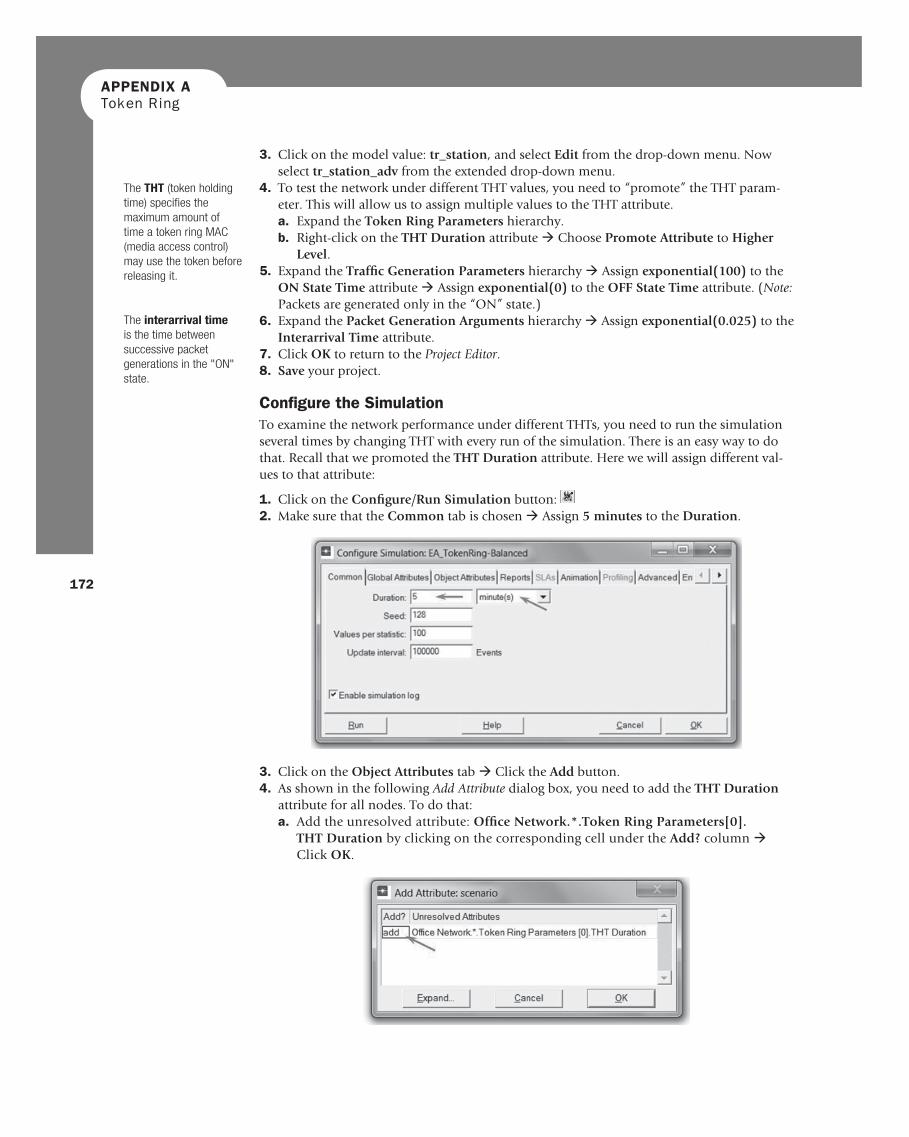
1. Click on the Confi gure/Run Simulation button: 2. Make sure that the Common tab is chosen · Assign 5 minutes to the Duration .
3. Click on the Object Attributes tab · Click the Add button. 4. As shown in the following Add Attribute dialog box, you need to add the THT Duration
attribute for all nodes. To do that: a. Add the unresolved attribute: Offi ce Network.*.Token Ring Parameters[0].
THT Duration by clicking on the corresponding cell under the Add? column · Click OK .
The THT (token holding time) specifi es the maximum amount of time a token ring MAC (media access control) may use the token before releasing it.
The interarrival time is the time between successive packet generations in the "ON" state.
173
ABOELELA 978-0-12-385210-6 00016
APPENDIX A Token Ring
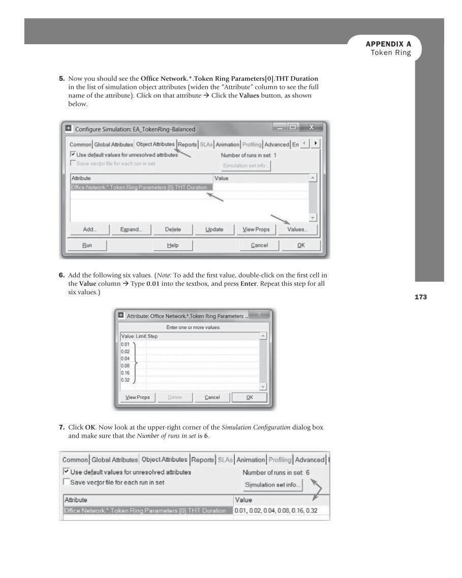
5. Now you should see the Offi ce Network.*.Token Ring Parameters[0].THT Duration in the list of simulation object attributes (widen the “Attribute” column to see the full name of the attribute). Click on that attribute · Click the Values button, as shown below.
6. Add the following six values. ( Note: To add the fi rst value, double-click on the fi rst cell in the Value column · Type 0.01 into the textbox, and press Enter . Repeat this step for all six values.)
7. Click OK . Now look at the upper-right corner of the Simulation Confi guration dialog box and make sure that the Number of runs in set is 6 .

APPENDIX AToken Ring
174
10. Click OK , and Save your project.
Choose the Statistics To choose the statistics to be collected during the simulation:
1. Right-click anywhere in the project workspace (but not on a node or link), and select Choose Individual Statistics from the pop up menu. a. Expand the Global Statistics hierarchy: ❍ Expand the Traffi c Sink hierarchy · Select Traffi c Received (packets/sec) . ❍ Expand the Traffi c Source hierarchy · Select Traffi c Sent (packets/sec) . ❍ Expand the Node Statistics hierarchy · Expand the Token Ring hierarchy ·
Select Utilization. b. Click OK .
2. Now we want to collect the average of the preceding statistics as a scalar value by the end of each simulation run. a. Select Choose Statistics (Advanced) from the Simulation menu. b. The Traffi c Sent and Traffi c Received probes should appear under the Global Statistic
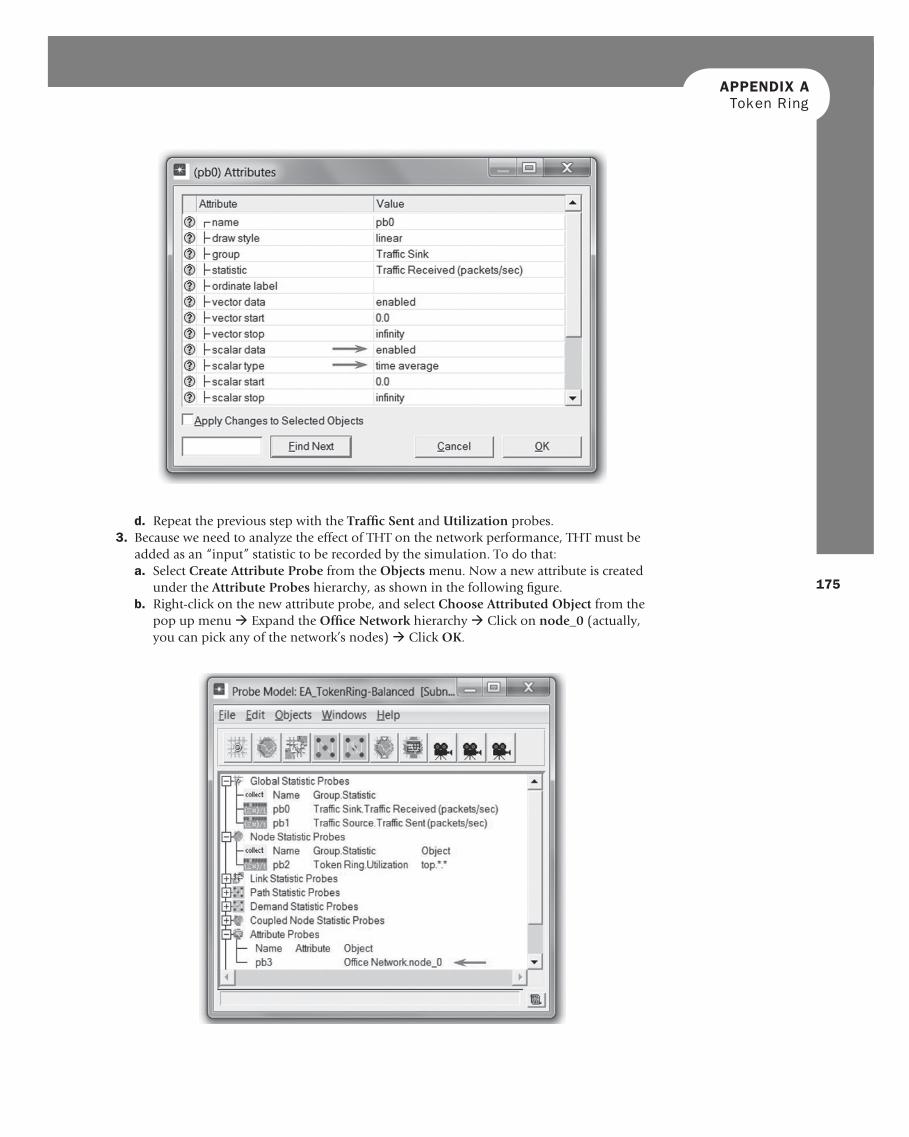
Probes. The Utilization probe should appear under the Node Statistics Probes. c. Right-click on Traffi c Received probe · Edit Attributes . Set the scalar data attribute
to enabled · Set the scalar type attribute to time average · Compare with the fol-lowing fi gure, and click OK .
8. For each of the six simulation runs, we need the simulator to save “scalar” values that represent the “average” values of the collected statistics. To save these scalars, we need to confi gure the simulator to save them in a fi le. Click on the Advanced tab in the Confi gure Simulation dialog box.
9. Assign < your initials>_Token-Balanced to the Scalar fi le text fi eld.
The utilization is a mea-sure of the bandwidth used versus that avail-able on the given ring.
A probe represents a request by the user to collect a particular piece of data about a simulation.
175
ABOELELA 978-0-12-385210-6 00016
APPENDIX A Token Ring
d. Repeat the previous step with the Traffi c Sent and Utilization probes. 3. Because we need to analyze the effect of THT on the network performance, THT must be
added as an “input” statistic to be recorded by the simulation. To do that: a. Select Create Attribute Probe from the Objects menu. Now a new attribute is created
under the Attribute Probes hierarchy, as shown in the following fi gure. b. Right-click on the new attribute probe, and select Choose Attributed Object from the
pop up menu · Expand the Offi ce Network hierarchy · Click on node_0 (actually, you can pick any of the network’s nodes) · Click OK .
APPENDIX AToken Ring
176
4. Select Save from the File menu in the Probe Model window, and then Close the window. 5. Now you are back to the Project Editor . Make sure to save your project.
Duplicate the Scenario The token ring network scenario we just implemented is balanced : the distribution of the gen-erated traffi c in all nodes is the same. To compare performance, you will create an “unbal-anced” scenario as follows:
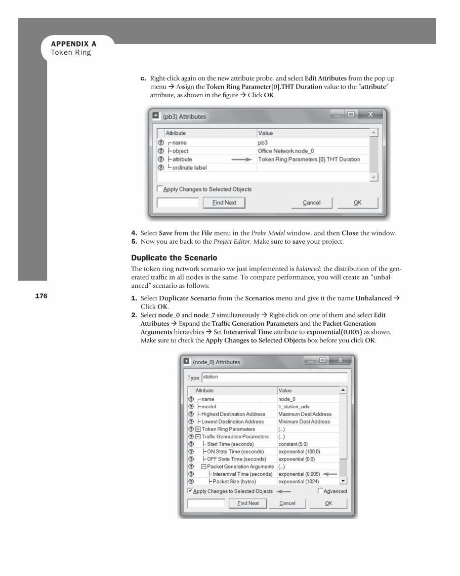
1. Select Duplicate Scenario from the Scenarios menu and give it the name Unbalanced · Click OK .
2. Select node_0 and node_7 simultaneously · Right-click on one of them and select Edit Attributes · Expand the Traffi c Generation Parameters and the Packet Generation Arguments hierarchies · Set Interarrival Time attribute to exponential(0.005) as shown. Make sure to check the Apply Changes to Selected Objects box before you click OK .
c. Right-click again on the new attribute probe, and select Edit Attributes from the pop up menu · Assign the Token Ring Parameter[0].THT Duration value to the “ attribute ” attribute, as shown in the fi gure · Click OK .
177
ABOELELA 978-0-12-385210-6 00016
APPENDIX A Token Ring
3. Select all nodes except node_0 and node_7 · Right-click on one of the selected nodes and select Edit Attributes · Change the value of the Interarrival Time attribute to exponential(0.075) as in the previous step. Make sure to check the Apply Changes to Selected Objects box before you click OK .
4. Click anywhere in the workspace to unselect objects · Click on the Confi gure/Run Simulation button: · Click on the Advanced tab in the Confi gure Simulation dialog box · Assign < your initials>_Token-Unbalanced to the Scalar fi le text fi eld.
5. Click OK , and Save your project.
Run the Simulation To run the simulation for both scenarios simultaneously:
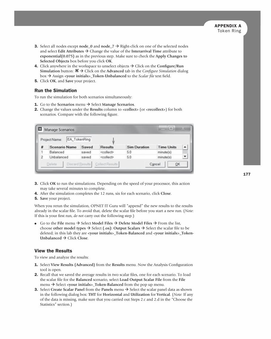
1. Go to the Scenarios menu · Select Manage Scenarios . 2. Change the values under the Results column to <collect> (or <recollect> ) for both
scenarios. Compare with the following fi gure.
3. Click OK to run the simulations. Depending on the speed of your processor, this action may take several minutes to complete.
4. After the simulation completes the 12 runs, six for each scenario, click Close . 5. Save your project.
When you rerun the simulation, OPNET IT Guru will “append” the new results to the results already in the scalar fi le. To avoid that, delete the scalar fi le before you start a new run. (Note: If this is your fi rst run, do not carry out the following step.)
● Go to the File menu · Select Model Files · Delete Model Files · From the list, choose other model types · Select (.os): Output Scalars · Select the scalar fi le to be deleted; in this lab they are < your initials>_Token-Balanced and < your initials>_Token-Unbalanced · Click Close .
View the Results To view and analyze the results:
1. Select View Results (Advanced) from the Results menu. Now the Analysis Confi guration tool is open.
2. Recall that we saved the average results in two scalar fi les, one for each scenario. To load the scalar fi le for the Balanced scenario, select Load Output Scalar File from the File menu · Select < your initials>_Token-Balanced from the pop up menu.
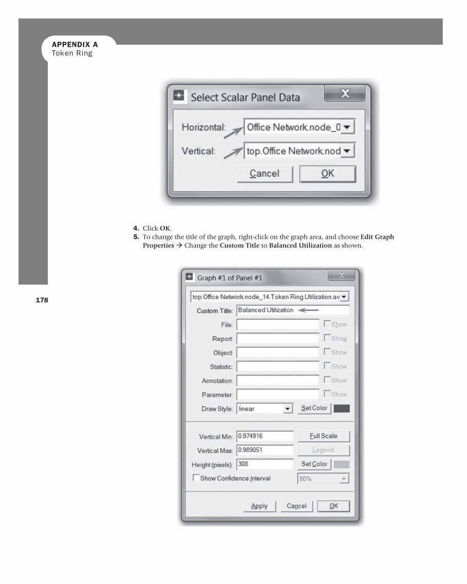
3. Select Create Scalar Panel from the Panels menu · Select the scalar panel data as shown in the following dialog box: THT for Horizontal and Utilization for Vertical . ( Note: If any of the data is missing, make sure that you carried out Steps 2.c and 2.d in the “ Choose the Statistics ” section.)
APPENDIX AToken Ring
178
4. Click OK . 5. To change the title of the graph, right-click on the graph area, and choose Edit Graph
Properties · Change the Custom Title to Balanced Utilization as shown.
179
APPENDIX A Token Ring
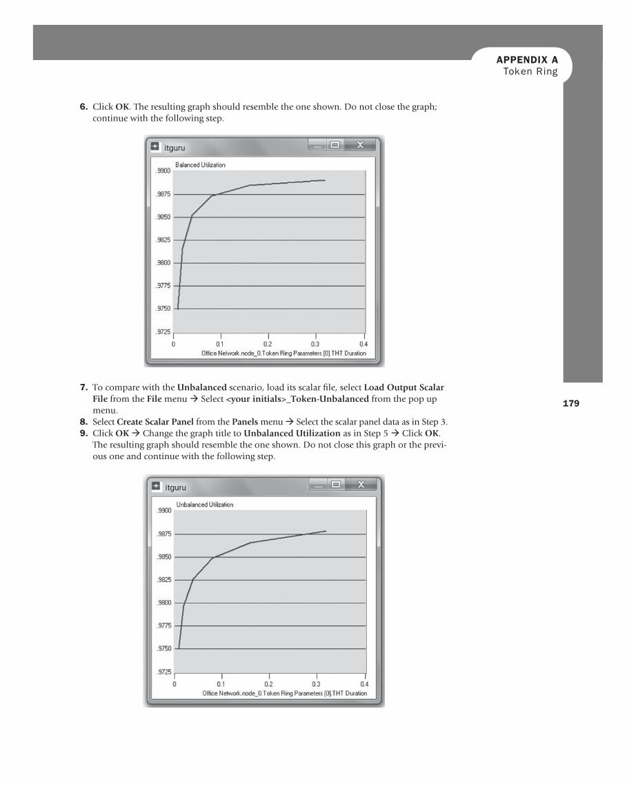
6. Click OK . The resulting graph should resemble the one shown. Do not close the graph; continue with the following step.
7. To compare with the Unbalanced scenario, load its scalar fi le, select Load Output Scalar File from the File menu · Select < your initials>_Token-Unbalanced from the pop up menu.
8. Select Create Scalar Panel from the Panels menu · Select the scalar panel data as in Step 3. 9. Click OK · Change the graph title to Unbalanced Utilization as in Step 5 · Click OK .
The resulting graph should resemble the one shown. Do not close this graph or the previ-ous one and continue with the following step.
APPENDIX AToken Ring
180
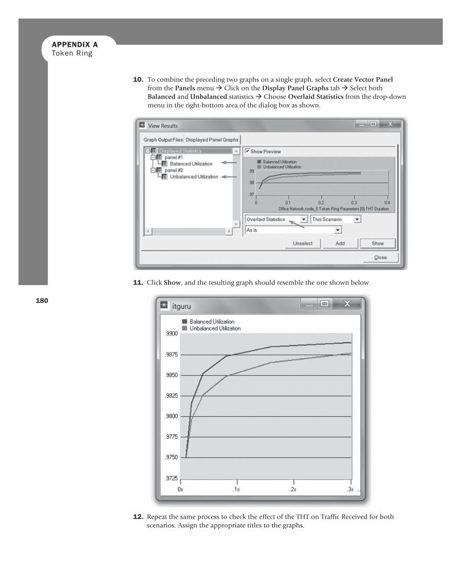
10. To combine the preceding two graphs on a single graph, select Create Vector Panel from the Panels menu · Click on the Display Panel Graphs tab · Select both Balanced and Unbalanced statistics · Choose Overlaid Statistics from the drop-down menu in the right-bottom area of the dialog box as shown.
11. Click Show , and the resulting graph should resemble the one shown below.
12. Repeat the same process to check the effect of the THT on Traffi c Received for both scenarios. Assign the appropriate titles to the graphs.
181
ABOELELA 978-0-12-385210-6 00016
APPENDIX A Token Ring
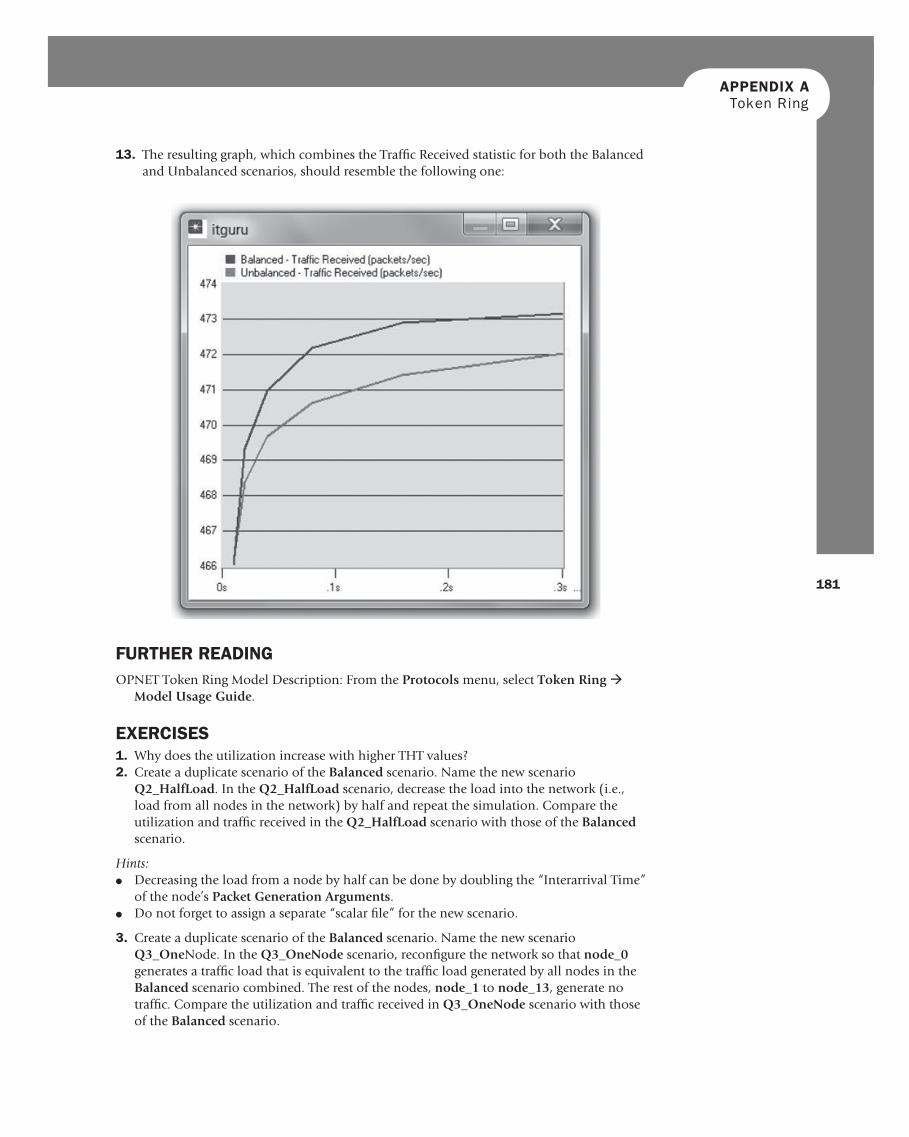
13. The resulting graph, which combines the Traffi c Received statistic for both the Balanced and Unbalanced scenarios, should resemble the following one:
FURTHER READING OPNET Token Ring Model Description: From the Protocols menu, select Token Ring ·
Model Usage Guide .
EXERCISES 1. Why does the utilization increase with higher THT values? 2. Create a duplicate scenario of the Balanced scenario. Name the new scenario
Q2_HalfLoad . In the Q2_HalfLoad scenario, decrease the load into the network (i.e., load from all nodes in the network) by half and repeat the simulation. Compare the utilization and traffi c received in the Q2_HalfLoad scenario with those of the Balanced scenario.
Hints: ● Decreasing the load from a node by half can be done by doubling the “Interarrival Time”
of the node’s Packet Generation Arguments . ● Do not forget to assign a separate “scalar fi le” for the new scenario.
3. Create a duplicate scenario of the Balanced scenario. Name the new scenario Q3_One Node. In the Q3_OneNode scenario, reconfi gure the network so that node_0 generates a traffi c load that is equivalent to the traffi c load generated by all nodes in the Balanced scenario combined. The rest of the nodes, node_1 to node_13 , generate no traffi c. Compare the utilization and traffi c received in Q3_OneNode scenario with those of the Balanced scenario.
APPENDIX AToken Ring
182
Hints: ● One way to confi gure a node so that it does not generate traffi c is to set its Start Time (it
is one of the Traffi c Generation Parameters ) to the special value Never . ● Do not forget to assign a separate “scalar fi le” for the new scenario.
LAB REPORT Prepare a report that follows the guidelines explained in the Introduction Lab. The report should include the answers to the preceding exercises as well as the graphs you generated from the simulation scenarios. Discuss the results you obtained, and compare these results with your expectations. Mention any anomalies or unexplained behaviors.