Embed Size (px)
Citation preview

© 2017 Littelfuse, Inc.Specifications are subject to change without notice.
Revised: 09/14/17
Metal-Oxide Varistors (MOVs)Radial Lead Varistors > TMOV® and iTMOV® Varistor Series
RoHS
Description
Features
• RoHS compliant and Lead–free available
• Designed to facilitate compliance to UL1449 for SPD products
• High peak surge current rating up to 10kA
• Wave solderable
• Standard lead form and spacing option
• -55°C to +85°C operating temp range
• Three-lead version available for indication purposes
Agency Approvals
Applications
• SPD Products
• AC Panel Protection Modules
• AC Line Power Supplies
• Surge Protected Strip Connectors
• AC Power Meters
• Relocatable AC Power Taps
• GFCI (Ground Fault Current Interupter)
• UPS (Uninterruptable Power Supply)
• White Goods
• Plug-in SPD
• Inverters
• AC/DC Power Supplies
Agency Agency Approval Agency File Number
UL1449 E320116
QC 42201-C001, QC 42201-A001,
IEC 60950-1 (Annex Q)IECQ-C BSI 15.0009
IEC 61051-1, IEC 61051-2,
IEC 60950-1 (Annex Q)40021525
TMOV® and iTMOV® Varistor Series
The Littelfuse TMOV® and iTMOV® thermally protected varistors represent a new development in integrated circuit protection. Both versions are comprised of radial leaded Metal Oxide Varistors (MOVs) with an integrated thermally activated element designed to open in the event of overheating due to the abnormal overvoltage, limited current, conditions outlined in UL1449. The TMOV® and iTMOV® varistor’s integrated thermal element, in conjunction with appropriate enclosure design, helps facilitate SPD module compliance to UL1449 for both cord connected and permanently connected applications.
The TMOV® and iTMOV® varistors offer quick thermal response due to the close proximity of the integrated thermal element to the MOV body. The integrated configuration also offers lower inductance than most discrete solutions resulting in improved clamping performance to fast overvoltage transients.
The iTMOV® varistor differs from the TMOV® varistor by the inclusion of a third lead for the purpose of indicating that the MOV has been disconnected from the circuit. This lead facilitates connection to monitoring circuitry.
Additionally TMOV® and iTMOV® varistors are wave solderable, thus simplifying end product assembly by reducing the the expense and rework associated with hand soldering operations.
Additional Information
Datasheet SamplesResources
Datasheet SamplesResources
iTMOV
TMOV
iTMOV
TMOV
iTMOV
TMOV

© 2017 Littelfuse, Inc.Specifications are subject to change without notice. Revised: 09/14/17
Metal-Oxide Varistors (MOVs)Radial Lead Varistors > TMOV® and iTMOV® Varistor Series
Ratings & Specifications
TMOV® VaristorLead–free And RoHSCompliant Models
iTMOV® Varistor Lead–free and RoHSCompliant Models Disc
Diameter
Maximum Rating (85°C) Specifications (25°C)Continuous Transient Varistor
Voltage at 1mA Test Current
Maximum Clamping Voltage 8/20µs
Typical Capaci-tance
f = 1MHz
AC Volts
DC Volts
Energy 2ms
Peak Surge Current 8/20µs
Part Number Branding Part
Number BrandingVM(AC)RMS VM(DC) WTM
ITM 1 × Pulse
ITM 2 × Pulse
VN(DC) Min
VN(DC) Max
VC IPK C
(mm) (V) (V) (J) (A) (A) (V) (V) (A) (pF)TMOV14RP115E P4T115E TMOV14RP115M P4T115M 14 115 150 35 6000 4500 162 198 300 50 1100TMOV20RP115E P2T115E TMOV20RP115M P2T115M 20 115 150 52 10000 6500 162 198 300 100 2400TMOV14RP130E P4T130E TMOV14RP130M P4T130M 14 130 170 50 6000 4500 184.5 225.5 340 50 1000TMOV20RP130E P2T130E TMOV20RP130M P2T130M 20 130 170 100 10000 6500 184.5 225.5 340 100 1900TMOV14RP140E P4T140E TMOV14RP140M P4T140M 14 140 180 55 6000 4500 198 242 360 50 900TMOV20RP140E P2T140E TMOV20RP140M P2T140M 20 140 180 110 10000 6500 198 242 360 100 1750TMOV14RP150E P4T150E TMOV14RP150M P4T150M 14 150 200 60 6000 4500 216 264 395 50 800TMOV20RP150E P2T150E TMOV20RP150M P2T150M 20 150 200 120 10000 6500 216 264 395 100 1600TMOV14RP175E P4T175E TMOV14RP175M P4T175M 14 175 225 70 6000 4500 243 297 455 50 700TMOV20RP175E P2T175E TMOV20RP175M P2T175M 20 175 225 135 10000 6500 243 297 455 100 1400TMOV14RP200E P4T200E TMOV14RP200M P4T200M 14 200 260 75 6000 4500 283 345 530 50 630TMOV20RP200E P2T200E TMOV20RP200M P2T200M 20 200 260 154 10000 6500 283 345 530 100 1250TMOV14RP230E P4T230E TMOV14RP230M P4T230M 14 230 300 80 6000 4500 324 396 595 50 550TMOV20RP230E P2T230E TMOV20RP230M P2T230M 20 230 300 160 10000 6500 324 396 595 100 1100TMOV14RP250E P4T250E TMOV14RP250M P4T250M 14 250 320 100 6000 4500 351 429 650 50 500TMOV20RP250E P2T250E TMOV20RP250M P2T250M 20 250 320 170 10000 6500 351 429 650 100 1000TMOV14RP275E P4T275E TMOV14RP275M P4T275M 14 275 350 110 6000 4500 387 473 710 50 450TMOV20RP275E P2T275E TMOV20RP275M P2T275M 20 275 350 190 10000 6500 387 473 710 100 900TMOV14RP300E P4T300E TMOV14RP300M P4T300M 14 300 385 125 6000 4500 423 517 775 50 400TMOV20RP300E P2T300E TMOV20RP300M P2T300M 20 300 385 250 10000 6500 423 517 775 100 800TMOV14RP320E P4T320E TMOV14RP320M P4T320M 14 320 420 136 6000 4500 459 561 840 50 380TMOV20RP320E P2T320E TMOV20RP320M P2T320M 20 320 420 270 10000 6500 459 561 840 100 750TMOV14RP385E P4T385E TMOV14RP385M P4T385M 14 385 505 150 6000 4500 558 682 1025 50 360TMOV20RP385E P2T385E TMOV20RP385M P2T385M 20 385 505 300 10000 6500 558 682 1025 100 700TMOV14RP420E P4T420E TMOV14RP420M P4T420M 14 420 560 160 6000 4500 612 748 1120 50 300TMOV20RP420E P2T420E TMOV20RP420M P2T420M 20 420 560 320 10000 6500 612 748 1120 100 600TMOV14RP460E P4T460E TMOV14RP460M P4T460M 14 460 610 180 6000 4500 675 825 1240 50 220TMOV20RP460E P2T460E TMOV20RP460M P2T460M 20 460 610 360 10000 6500 675 825 1240 100 200TMOV14RP510E P4T510E TMOV14RP510M P4T510M 14 510 670 185 6000 4500 738 902 1355 50 200TMOV20RP510E P2T510E TMOV20RP510M P2T510M 20 510 670 325 10000 6500 738 902 1355 100 350TMOV14RP550E P4T550E TMOV14RP550M P4T550M 14 550 715 190 6000 4500 819 1001 1500 50 180TMOV20RP550E P2T550E TMOV20RP550M P2T550M 20 550 715 360 10000 6500 819 1001 1500 100 300
Absolute Maximum Ratings
Continuous TMOV® and iTMOV® Varistor Series UnitsSteady State Applied Voltage: AC Voltage Range (VM(AC)RMS) 115 to 750 VTransient:Peak Pulse Current (ITM) - For 8x20µs Current Wave, single pulse 6,000 to 10,000 ASingle-Pulse Energy Capability - For 2ms Current Wave 35 to 480 JOperating Ambient Temperature Range (TA) -55 to +85 °CStorage Temperature Range (TSTG) -55 to +125 °CTemperature Coefficient (αV) of Clamping Voltage (VC) at Specified Test Current <0.01 %/°CHi-Pot Encapsulation (COATING Isolation Voltage Capability) 2,500 VThermal Protection Isolation Voltage Capability (when operated) 600 VCOATING Insulation Resistance 1,000 MΩIndicator Lead Rating (Lead-3 - iTMOV® varistor only): Continuous RMS current 100 mA Surge Current, 8/20µs 10,000 A
CAUTION: Stresses above those listed in “Absolute Maximum Ratings” may cause permanent damage to the device. This is a stress only rating and operation of the device at these or any other conditions above those indicated in the operational sections of this specification is not implied.
• For ratings of individual members of a series, see Device Ratings and Specifications chart

© 2017 Littelfuse, Inc.Specifications are subject to change without notice.
Revised: 09/14/17
Metal-Oxide Varistors (MOVs)Radial Lead Varistors > TMOV® and iTMOV® Varistor Series
Note : The TMOV® and iTMOV® varistors are intended, in conjunction with appropriate enclosure design, to help facilitate SPD module compliance to UL 1449, 3rd Edition Section 39.4 (abnormal overvoltage limited current requirements). Under these extreme abnormal overvoltage conditions, some units will exhibit substantial heating, arcing and venting prior to opening. Modules should be designed to contain this possibility. Application testing is strongly recommended.
Thermal Characteristics
* Figure 4: Typical time to open circuit under UL1449 Abnormal Overvoltage Limited Current Test
0.1
1
10
10 100 1000 10000Time(s)
0.125A0.5A2.5A5A
Typical
100
1000
10000
0.000001 0.00001 0.0001 0.001 0.01 0.1 1 10 100 1000 10000Peak Current (A)
Cla
mpi
ng V
olta
ge (V
)
175V150V140V130V
320V300V275V
250V230V
Figure 6: V-I Characteristic Curves for 14mm Types
420V385V
115V
Maximum Leakage Current
Maximum Clamping Voltage
200V
460V510V550V575V625V750V
Maximum Clamping Voltage for 14mm Parts Maximum Clamping Voltage for 20mm Parts
100
1000
10000
0.000001 0.00001 0.0001 0.001 0.01 0.1 1 10 100 1000 10000
Peak Current (A)
Cla
mpi
ng V
olta
ge (
V)
1 7 5 V1 5 0 V1 4 0 V1 3 0 V
3 2 0 V
2 7 5 V
2 5 0 V2 3 0 V
Figure 7: V-I Characteristic Curves for 20mm Types
4 2 0 V3 8 5 V
1 1 5 V
Maximum Leakage Current
Maximum Clamping Voltage
2 0 0 V
4 6 0 V5 1 0 V5 5 0 V5 7 5 V6 2 5 V 7 5 0 V
3 0 0 V
Figure 1
Figure 3 Figure 4
Ratings & Specifications
TMOV® Varistor Lead–free And RoHSCompliant Models
iTMOV® Varistor Lead–free and RoHSCompliant Models Disc
Diameter
Maximum Rating (85°C) Specifications (25°C)Continuous Transient
Varistor Voltage at 1mA Test
Current
Maximum Clamping
Voltage 8/20µs
Typical Capaci-tance
f = 1MHz
AC Volts
DC Volts
Energy 2ms
Peak Surge Current 8/20µs
Part Number Branding Part
Number BrandingVM(AC)RMS VM(DC) WTM
ITM 1 × Pulse
ITM 2 × Pulse
VN(DC) Min
VN(DC) Max VC IPK C
(mm) (V) (V) (J) (A) (A) (V) (V) (A) (pF)TMOV14RP575E P4T575E TMOV14RP575M P4T575M 14 575 730 195 6000 4500 857 1047 1568 50 170TMOV20RP575E P2T575E TMOV20RP575M P2T575M 20 575 730 375 10000 6500 857 1047 1568 100 275TMOV14RP625E P4T625E TMOV14RP625M P4T625M 14 625 825 200 6000 4500 900 1100 1650 50 160TMOV20RP625E P2T625E TMOV20RP625M P2T625M 20 625 825 400 10000 6500 900 1100 1650 100 250TMOV14RP750E P4T750E TMOV14RP750M P4T750M 14 750 970 210 6000 4500 1080 1320 1980 50 140TMOV20RP750E P2T750E TMOV20RP750M P2T750M 20 750 970 480 10000 6500 1080 1320 1980 100 175
100
80
60
40
20
0-55 50 60 70 80 90 100 110 120 130
AMBIENT TEMPERATURE ( oC)
PE
RC
EN
T O
F R
ATE
D V
AL
UE
Current, Energy, Power Derating Curve
For applications exceeding 85°C ambient temperature, the peak surge current and energy ratings must be reduced as shown above.
Figure 2

© 2017 Littelfuse, Inc.Specifications are subject to change without notice. Revised: 09/14/17
Metal-Oxide Varistors (MOVs)Radial Lead Varistors > TMOV® and iTMOV® Varistor Series
Repetitive Surge Capability for 14mm Parts Repetitive Surge Capability for 20mm Parts
Wave Solder Profile
NOTE: Average power dissipation of transients should not exceed 0.6W NOTE: Average power dissipation of transients should not exceed 1.0W
Operating/Storage Temperature
-55°C to +85°C
Humidity Aging+85°C, 85% RH , 1000 hours +/-10% typical voltage change
Thermal Shock+85°C to -55°C 5 times +/-10% typical voltage change
Solvent Resistance MIL–STD–202, Method 215
Moisture Sensitivity Level 1, J-STD-020
Lead Material Copper clad steel wire
Soldering Characteristics
Solderability per MIL–STD–202, Method 208
Insulating MaterialCured, flame retardant epoxy polymer meets UL94 V–0 requirements
Device LabelingMarked with LF, voltage, UL/CSA logos, and date code
Physical Specifications Environmental Specifications
Because the TMOV® and iTMOV® varistors contain a thermal protection device, care must be taken when soldering the devices into place. Two soldering methods are possible. Firstly, hand soldering: It is recommended to heat-sink the leads of the device. Secondly, wave solder-ing: It is critically important that all preheat stage and the solder bath temperatures are rigidly controlled.
0
50
100
150
200
250
300
0 0.5 1 1.5 2 2.5 3 3.5 4
TIME(MINUTES)
TEM
PE
RA
TUR
E (º
C)
Maximum Wave 240C
Lead–free Profile
0
50
100
150
200
250
300
0 0.5 1 1.5 2 2.5 3 3.5 4
TIME(MINUTES)
TEM
PER
ATU
RE
(ºC)
Maximum Wave 260C
Non Lead–free Profile
Figure 9: Pulse Rating Curves for 20mm types
1
10
100
1000
10000
10 100 1000 10000
Impulse Duration (μs)
Peak
Cur
rent
(A)
1
102
103
2
104
105
106
15
Figure 8: Pulse Rating Curves for 14mm types
1
10
100
1000
10000
10 100 1000 10000
Impulse Duration (µs)
Pea
k C
urr
ent
(A)
1 15
102
103
2
104
105
106
Figure 5 Figure 6
Figure 7 Figure 8
© 2017 Littelfuse, Inc.Specifications are subject to change without notice.
Revised: 09/14/17
Metal-Oxide Varistors (MOVs)Radial Lead Varistors > TMOV® and iTMOV® Varistor Series
1
2
3
3
21
ThermalFuseElement
MOV
ThermalFuseElement
MOV
Monitor Lead
Monitor Lead
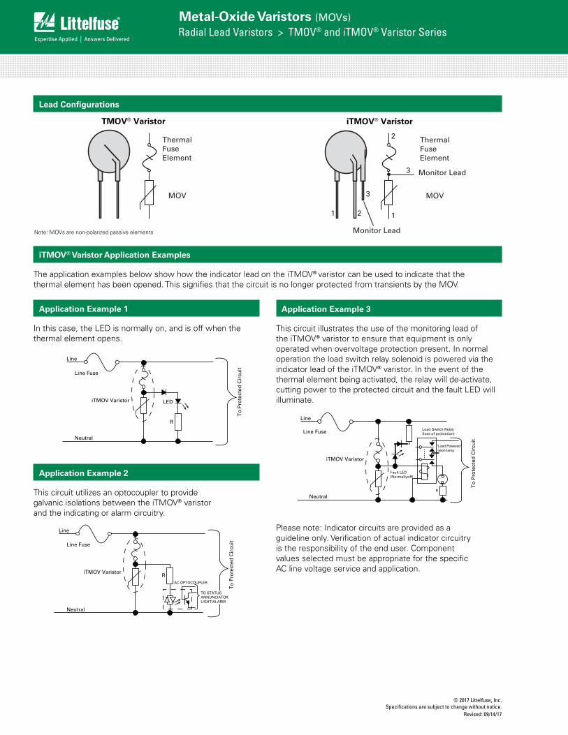
Lead Configurations
TMOV® Varistor iTMOV® Varistor
iTMOV® Varistor Application Examples
The application examples below show how the indicator lead on the iTMOV® varistor can be used to indicate that the thermal element has been opened. This signifies that the circuit is no longer protected from transients by the MOV.
R
LED
Line Fuse
iTMOV Varistor
Neutral
Line
Figure 1. Application example 1
R
Line Fuse
iTMOV Varistor
Neutral
Figure 2. Application example 2
AC OPTOCOUPLER
TO STATUSANNUNCIATORLIGHT/ALARM
Line Fuse
iTMOV Varistor
Neutral
Figure 3. Application example 3
Fault LED(Normallyoff)
"Load Powered" neon lamp
Load Switch Relay(loss of protection)
R
To
Pro
tect
ed C
ircu
itT
o P
rote
cted
Cir
cuit
To
Pro
tect
ed C
ircu
it
Line
Line
Note: MOVs are non-polarized passive elements
Application Example 1
In this case, the LED is normally on, and is off when the thermal element opens.
Application Example 2
This circuit utilizes an optocoupler to provide galvanic isolations between the iTMOV® varistor and the indicating or alarm circuitry.
Application Example 3
This circuit illustrates the use of the monitoring lead of the iTMOV® varistor to ensure that equipment is only operated when overvoltage protection present. In normal operation the load switch relay solenoid is powered via the indicator lead of the iTMOV® varistor. In the event of the thermal element being activated, the relay will de-activate, cutting power to the protected circuit and the fault LED will illuminate.
R
LED
Line Fuse
iTMOV Varistor
Neutral
Line
Figure 1. Application example 1
R
Line Fuse
iTMOV Varistor
Neutral
Figure 2. Application example 2
AC OPTOCOUPLER
TO STATUSANNUNCIATORLIGHT/ALARM
Line Fuse
iTMOV Varistor
Neutral
Figure 3. Application example 3
Fault LED(Normallyoff)
"Load Powered" neon lamp
Load Switch Relay(loss of protection)
R
To
Pro
tect
ed C
ircu
itT
o P
rote
cted
Cir
cuit
To
Pro
tect
ed C
ircu
it
Line
Line
R
LED
Line Fuse
iTMOV Varistor
Neutral
Line
Figure 1. Application example 1
R
Line Fuse
iTMOV Varistor
Neutral
Figure 2. Application example 2
AC OPTOCOUPLER
TO STATUSANNUNCIATORLIGHT/ALARM
Line Fuse
iTMOV Varistor
Neutral
Figure 3. Application example 3
Fault LED(Normallyoff)
"Load Powered" neon lamp
Load Switch Relay(loss of protection)
R
To
Pro
tect
ed C
ircu
itT
o P
rote
cted
Cir
cuit
To
Pro
tect
ed C
ircu
it
Line
Line
Please note: Indicator circuits are provided as a guideline only. Verification of actual indicator circuitry is the responsibility of the end user. Component values selected must be appropriate for the specific AC line voltage service and application.

© 2017 Littelfuse, Inc.Specifications are subject to change without notice. Revised: 09/14/17
Metal-Oxide Varistors (MOVs)Radial Lead Varistors > TMOV® and iTMOV® Varistor Series
Device Dimensions
DimensionVRMS
Voltage Model
TMOV® Varistor iTMOV® Varistor
14mm Size 20mm Size 14mm Size 20mm Size
Min. mm (in)
Max. mm (in)
Min. mm (in)
Max.mm (in)
Min. mm (in)
Max.mm (in)
Min.mm (in)
Max.mm (in)
AStraight Lead
ALL 17.0 (0.669) 22.0 (0.866) 23.0 (0.906) 28.0 (1.10) 17.0 (0.669) 22.0 (0.866) 23.0 (0.906) 28.0 (1.10)
ACrimped Lead
ALL -- 22.5 (0.886) -- 31.0 (1.221) -- 22.5 (0.886) -- 31.0 (1.221)
Dia D ALL 13.5 (0.531) 17.0 (0.669) 19.0 (0.748) 23.0 (0.906) 13.5 (0.531) 17.0 (0.669) 19.0 (0.748) 23.0 (0.906)
e ALL 6.5 (0.256) 8.5 (0.335) 6.5 (0.256) 8.5 (0.335) 6.5 (0.256) 8.5 (0.335) 6.5 (0.256) 8.5 (0.335)
e1Bulk Pack
115-175 1.5 (0.059) 4.0 (0.157) 1.5 (0.059) 4.0 (0.157) 1.5 (0.059) 4.0 (0.157) 1.5 (0.059) 4.0 (0.157)
200-275 2.0 (0.079) 4.5 (0.177) 2.0 (0.079) 4.5 (0.177) 2.0 (0.079) 4.5 (0.177) 2.0 (0.079) 4.5 (0.177)
300-420 3.0 (0.118) 5.5 (0.217) 3.0 (0.118) 5.5 (0.217) 3.0 (0.118) 5.5 (0.217) 3.0 (0.118) 5.5 (0.217)
460-750 0 2.0 (0.079) 0 2.0 (0.079) 0 2.0 (0.079) 0 2.0 (0.079)
e1Tape & Reel and
In-Line Lead
115-420 0 2.0 (0.079) 0 2.0 (0.079) 0 2.0 (0.079) 0 2.0 (0.079)
460-550* 0 2.0 (0.079) 0 2.0 (0.079) 0 2.0 (0.079) 0 2.0 (0.079)
e2 ALL n/a n/a n/a n/a 4.0 (0.157) 6.0 (0.236) 4.0 (0.157) 6.0 (0.236)
e3 ALL n/a n/a n/a n/a 0 2.0 (0.079) 0 2.0 (0.079)
E
115-175 -- 9.0 (0.354) -- 9.0 (0.354) -- 9.0 (0.354) -- 9.0 (0.354)
200-275 -- 9.5 (0.374) -- 9.5 (0.374) -- 9.5 (0.374) -- 9.5 (0.374)
300-460 -- 11.0 (0.433) -- 11.0 (0.433) -- 11.0 (0.433) -- 11.0 (0.433)
510-575 -- 12.0 (0.472) -- 12.0 (0.472) -- 12.0 (0.472) -- 12.0 (0.472)
625-750 -- 13.0 (0.512) -- 13.0 (0.512) -- 13.0 (0.512) -- 13.0 (0.512)
L ALL 25.4 (1.00) -- 25.4 (1.00) -- 25.4 (1.00) -- 25.4 (1.00) --
L3 ALL n/a n/a n/a n/a 6.0 (0.236) -- 6.0 (0.236) --
Dia b115-420 0.76 (0.030) 0.86 (0.034) 0.76 (0.030) 0.86 (0.034) 0.76 (0.030) 0.86 (0.034) 0.76 (0.030) 0.86 (0.034)
460-750 0.76 (0.030) 0.86 (0.034) 0.95 (0.037) 1.05 (0.041) 0.76 (0.030) 0.86 (0.034) 0.95 (0.037) 1.05 (0.041)
Dia cOutside Lead Only ALL n/a n/a n/a n/a 0.76 (0.030) 0.86 (0.034) 0.76 (0.030) 0.86 (0.034)
NOTES:* Tape and Reel packaging option is available only for devices up to 420Vrms.
E
e e1 e1
e3
ee2
E
L
A
L3
Dia D Dia D
Dia b Dia b
Dia c
Monitor Lead
TMOV® Varistor
Straight Lead Forms
iTMOV® Varistor
E
e e1 e1
e3
ee2
E
L
A
L3
Dia D Dia D
Dia b Dia b
Dia c
Monitor Lead
TMOV® Varistor(outer crimp)
iTMOV® Varistor(inner crimp)
Curved Lead Forms
SeatingPlane

© 2017 Littelfuse, Inc.Specifications are subject to change without notice.
Revised: 09/14/17
Metal-Oxide Varistors (MOVs)Radial Lead Varistors > TMOV® and iTMOV® Varistor Series
DESCRIPTION CRIMPED LEADS STRAIGHT LEADS
MODEL SIZE MODEL SIZE14mm 20mm 14mm 20mm
B1 Component Top to Seating Plane 22.5 Max 31 Max 22.0 Max 28.0 Max
P Pitch of Component 25.4 +/- 1.0 25.4 +/- 1.0 25.4 ±1.0 25.4 ±1.0
P0 Feed Hole Pitch 12.7 +/- 0.2 12.7 +/- 0.2 12.7 ±0.2 12.7 ±0.2
P1 Feed Hole Center to Pitch 8.95 +/- 0.7 8.95 +/- 0.7 8.95 ±0.7 8.95 ±0.7
P2 Hole Center to Component Center 12.7 +/- 0.7 12.7 +/- 0.7 12.7 ±0.7 12.7 ±0.7
F Lead to Lead Distance 7.5 +/- 0.8 7.5 +/- 0.8 7.5 ±0.8 7.5 ±0.8
Δh Component Alignment 2.0 Max 2.0 Max 2.0 Max 2.0 Max
W Tape Width 18.0 +1.0/-0.5 18.0 +1.0/-0.5 18.0 +1.0/-0.5 18.0 +1.0/-0.5
W0 Hold Down Tape Width 12.0 +/- 0.3 12.0 +/- 0.3 12.0 ±0.3 12.0 ±0.3
W1 Hole Position 9.0 +0.75/-0.50 9.0 +0.75/-0.50 9.0 +0.75/-0.5 9.0 +0.75/-0.5
W2 Hold Down Tape Position 0.5 Max 0.5 Max 0.5 Max 0.5 Max
H Height from Tape Centre to Component Base (non-crimped parts) -- -- 18.0 +2.0/-0 18.0 +2.0/-0
H0 Seating Plane Height (crimped parts only) 16.0 +/- 0.5 16.0 +/- 0.5 -- --
H1 Component Height 40.0 Max 46.5 Max 40.0 Max 46.5 Max
C Crimp Length (crimped parts only) 2.6 typ 2.6 typ -- --
D0 Feed Hole Diameter 4.0 +/- 0.2 4.0 +/- 0.2 4.0 ±0.2 4.0 ±0.2
t Total Tape Thickness 0.7 +/- 0.2 0.7 +/- 0.2 0.7 ±0.2 0.7 ±0.2
L Length of Clipped Lead 11.0 Max 11.0 Max 11.0 Max 11.0 Max
Δp Component Alignment 3 Max. 1.00mm 3 Max 3 deg Max, 1.0mm Max
3 deg Max, 1.0mm Max
Tape and Reel Specification
SEATING PLANE
Øb
C
P2 ∆P
P
W2
tF
W0
W
W1
∆H∆H∆P
E
ØD0
P1
P0
H1
H0
B1
Øb
P2 ∆P
P
W2
tF
W0
W
W1
∆H∆H∆P
E
ØD0
P1
P0
H1
H
L
TMOV® VARISTOR WITH OUTER CRIMP
TMOV® VARISTOR WITH STRAIGHT LEADS
SEATING PLANE
Øb
C
P2 ∆P
P
W2
tF
W0
W
W1
∆H∆H∆P
E
ØD0
P1
P0
H1
H0
B1
Øb
P2 ∆P
P
W2
tF
W0
W
W1
∆H∆H∆P
E
ØD0
P1
P0
H1
H
L
iTMOV® VARISTOR WITH INNER CRIMP
iTMOV® VARISTOR WITH STRAIGHT LEADS
NOTES:
• Dimensions in mm
• Reel capacity varies with voltage.
• Leads are crimped and in-line. This excludes the monitor lead on iTMOV® varistor which are not crimped and not in-line.
• To order tape and reel option please add suffix 'L2T7' to end of standard part number.
• Tape and reel option is available for rated voltages up to 420V. Contact factory regarding availability of higher voltages.
• Contact Littelfuse for additional details.

© 2017 Littelfuse, Inc.Specifications are subject to change without notice. Revised: 09/14/17
Metal-Oxide Varistors (MOVs)Radial Lead Varistors > TMOV® and iTMOV® Varistor Series
Part Numbering System
TMOV 20 R E150
DEVICE FAMILYLittelfuse Thermally Protected MOV
DISC DIAMETER (mm)14 or 20mm
CERAMIC SHAPER: Round
SERIES DESIGNATORE: TMOV (2-Leaded, without indicator lead)M: iTMOV (3-Leaded, with indicator lead option)
V M(AC)RMS
115V to 750V
XXXXX
NON-STANDARD LEAD FORM, PACKAGING and LEAD SPACING OPTIONS1:
L2B7: Lead Form: Crimped and In-Line2 Leads Packaging: Bulk Pack Lead Spacing3: 7.5mm
L2T7: Lead Form: Crimped and In-Line2 Leads Packaging: Tape and Reel4
Lead Spacing3: 7.5mm
L3T7: Lead Form: Straight Leads and In-Line2 Leads Packing: Tape and Reel Lead Spacing: 7.5mm
Option Codes: X2855: Nickel Barrier coated wire option -- All standard parts use tinned copper clad steel wire. Nickel Barrier coated wire is available as an option, consisting of Copper wire with a flashing of Nickel followed by a top coating of Tin. To order append standard model BASE PART number with "X2855." Example: Standard Model Order As TMOV20RP115E TMOV20RP115EX2855
Other non-standard options may be available - please contact Littelfuse.
Base Part Codes(See ratings & specifications tables and notes below)
Option Codes1
(See below)
P
LEAD-FREE/RoHS COMPLIANT INDICATOR
NOTES:
1 Use Base Part Code only to receive standard product: Lead Form: Straight Leads. Devices greater than 420Vrms are provided In-Line2. Packaging: Bulk Pack Lead Spacing: 7.5mm +/-1.0mm
2 “In-Line” refers to straight row of leads at the tip where product is to contact the circuit board. Refer to “e1” in Device Dimensions section.
3 Lead Spacing refers to span between leads as “e” dimension in Device Dimensions section.
4 Due to device bulk, tape and reel packaging option is available only for devices up to 420Vrms.
Pack Quantities
Rated Voltage
Pack Quantities
Bulk Pack Tape and Reel
Model Size Model Size
14mm 20mm 14mm 20mm
115-250 600 400 500 400
275-550 500 300 400 300
575-750 400 200 n/a n/a
NOTE: Tape and Reel available up to 420V only - please contact factory regarding availability of higher voltage parts.
Disclaimer Notice - Information furnished is believed to be accurate and reliable. However, users should independently evaluate the suitability of and test each product selected for their own applications. Littelfuse products are not designed for, and may not be used in, all applications. Read complete Disclaimer Notice at www.littelfuse.com/disclaimer-electronics.


![(MLV) MULTILAYER CHIP VARISTOR - fenghua.comfenghua.com/pdf/varistor/chip_varistor.pdf · (MLV) MULTILAYER CHIP VARISTOR Multilayer Chip ... [2220] 8063[3225] 1080[4032] 55 125 V](https://img.dokumen.tips/doc/110x75/5b42af3a7f8b9ad23b8b5240/mlv-multilayer-chip-varistor-mlv-multilayer-chip-varistor-multilayer-chip.jpg)