Embed Size (px)
Citation preview

TMI HORNET BACKHOE
OPERATION & INSTALLATION MANUAL BACKHOE
Hornet 5600,6600,7600 & 8600 Backhoes
2
TABLE OF CONTENTS
SECTION PAGE SECTION PAGE Safety ....................................2 Removal/Storage .....................16 Safety Decals …........................3 Hydraulic Trouble Shooting .......18 Federal Laws and Regulations ....6 Valve Repair ............................21 General Operation ....................7 Control Valves ……………………….23 Controls ..................................8 Assembly ................................25 Operating The Backhoe .............9 Hydraulic Hook-Up ...................26 Placing The Stabilizers ..............9 and 11 Mounting Kits ...........................28 Transporting The Backhoe ........11 Bucket Spec ………………………………..37 Filling The Bucket ....................12 Torque Values …………………………………....38 Backfilling ..............................13 Service Notes …………………….……….…39 Service ..................................14 Parts ……………………………………………….41/49 Beginning Of The Season .........14 Hydraulic System .....…............14 Lubrication ............................15 Warranty………………………………………. 50 & 51
UNDERSTAND SIGNAL WORDS DANGER: Indicates an imminently hazardous situation which, if not avoided, will result in death or serious injury. This signal word is to be limited to the most extreme situations.
WARNING: Indicates a potentiallyhazardous situation which, if not avoided, could result in death or serious injury.
CAUTION: Indicates a potentially hazardous situation which, if not avoided, may result in minor or moderate injury. It may also be used to alert against unsafe practices.
IMPORTANT SAFETY PRECAUTIONS This symbol is used to call attention to safety precautions that should be followed by the operator to avoid accidents. When you see this symbol, carefully read the message that follows and heed its advice. Failure to comply with safety precautions could result in serious
bodily injury.
In addition to the design and configuration of equipment, hazard control and accident prevention aredependent upon the awareness, concern, prudence, and proper training of personnel in the operation,transport, maintenance and storage of equipment. Lack of attention to safety can result in accident, personal injury, reduction of efficiency and worst of all-loss of life. Watch for safety hazards and correctdeficiencies promptly. Use the following safety precautions as a general guide to safe operations when using this machine. Additional safety precautions are used throughout this manual for specific operating and maintenance procedures. Read this manual and review the safety precautions often until you know the limitations.
AVOID HIGH-PRESSURE FLUID ESCAPING fluid under pressure can have sufficient force to penetrate the skin and cause serious injury. Be sure to stop engine and relieve all pressure before disconnecting lines. Be sure all connections are tight and that lines, pipes, and hoses are not damaged before applying pressure to the system. Fluid escaping not your hands-to search for suspected leaks. SEE A DOCTOR at once if injured by escaping fluid. Serious infection or gangrene can develop if proper medical treatment is not administered immediately.
3
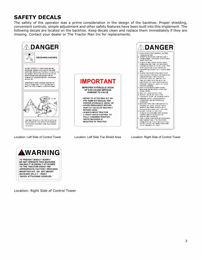
SAFETY DECALS The safety of the operator was a prime consideration in the design of the backhoe. Proper shielding, convenient controls, simple adjustment and other safety features have been built into this implement. The following decals are located on the backhoe. Keep decals clean and replace them immediately if they are missing. Contact your dealer or The Tractor Man Inc for replacements.
Location: Left Side of Control Tower Location: Left Side Toe Shield Area Location: Right Side of Control Tower
Location: Right Side of Control Tower
4
SAFETY PRECAUTIONS CONTINUED THE TRACTOR AND/OR LOADER (IF EQUIPPED)
1. Read the tractor and/or loader operator's manual to learn how to operate your tractor and/or loadersafely. Failure to do so could result in serious injury or death and equipment damage.
2. It is recommended that tractor be equipped with Rollover Protective System (ROPS) and a seat belt beused for all loader operations
3. Add wheel ballast or front weight for stability.
4. Move wheels to the tractor manufacture's widest recommended settings to increase stability.
5. For better stability, use tractor with wide front axle rather than tricycle front wheels.
6. Move and turn the tractor at low speeds.
7. Stop tractor engine, place transmission in park (or neutral), engage parking break, lower loader armsto ground, cycle all hydraulic controls to relieve pressure, allow machine moving parts to stop, removeignition key to prevent unauthorized person from starting engine before dismounting tractor orserving, repairing, or making adjustments to the equipment.
8. Wear personal protective equipment (PPE), such as, but not limited to, protection for eyes, ears, lungs,head. hands and feet when operating, servicing, or repairing equipment. Avoid wearing loose clothingor jewelry that may catch and entangle on equipment moving parts.
THE BACKHOE
1. DO NOT operate the backhoe unless it is rigidly attached to the tractor.
2. KNOW your controls. Read this operator's manual and the manual provided with your tractor. Learn how to stopthe tractor, the engine and the backhoe quickly in an emergency.
3. PROVIDE adequate front end weight to counter-balance the backhoe at all times. 20% of the total tractor, loaderand backhoe weight must be on the tractor front axle. If unsure of weight distribution, at a weight scale. Totalvehicle weight, including backhoe and counter weights, must not exceed the ROPS certificate for gross vehicleweight.
4. BE SURE the area is clear of overhead or underground utilities or other hazards.
5. POSITION a barricade around the work area.
6. KEEP all bystanders a safe distance away.
7. DO NOT attempt to enter operator's platform backhoe by using the stabilizers as a step.
8. OPERATE from the backhoe operator's seat only.
9. ALLOW only one person to operate the backhoe at any time.
10. DISENGAGE safety locks as shown in Figure 1&3 before attempting to operate the backhoe.
11. NEVER dig with the backhoe unless the stabilizers are properly set.
12. DO NOT dig under stabilizers or tractor backhoe. Soft ground or sandy soil can cause cave-ins.
13. KEEP BUCKET away from the stabilizer area to avoid possible stabilizer damage.
5
14. ALWAYS swing bucket uphill to dump when on a hillside and keep loaded bucket low.
15. SET BRAKES and block wheels when operating on hills and banks to avoid dangerous runaway.
16. WATCH for overhead wires. DO NOT touch wires with any part of the backhoe.
17. NEVER allow a person to work under a raised bucket.
18. NEVER lift a person with the backhoe.
19. DO NOT use the backhoe as a battering ram. Use the backhoe only for digging.
20. ALWAYS lower the backhoe bucket and stabilizers to the ground, shut off engine, and apply the parkingbreak before getting off unit, or when not digging.
21. NEVER leave the tractor unattended with the engine running.
22. DO NOT attempt to raise the tractor off the ground or move the tractor forward or backward using the backhoeDipper stick or bucket.
TRANSPORTATION 1. ALWAYS engage safety locks before transporting backhoe. See Figure 1 & 3.
2. DO NOT drive the tractor near the edge of a ditch or excavation.
3. ALWAYS use accessory lights and devices when transporting on a road or highway to warn operators of othervehicles. Check your local government regulations.
4. BE SURE the SMV emblem is visible to the rear.
ADJUSTMENTS AND INSPECTION 1. CHECK pins that attach backhoe to tractor and all pivot pins for tightness several times daily. Replace
any parts that are bent, broken or missing. 2. ALWAYS engage safety locks before servicing backhoe. See Figures 1 & 3.3. DO NOT oil, grease, or adjust the backhoe while it is in motion. For greasing, see Service section for details.
4. DO NOT change any backhoe relief valve settings. They are factory set for best backhoe performance and safety.
5. PROTECT YOUR EYES - WEAR SAFETY GLASSES.
6. GUARD AGAINST INJURY when driving connecting pins or performing any repair in which particles canchip from work piece or striking tool.
7. DO NOT remove any guards on backhoe or tractor.
6
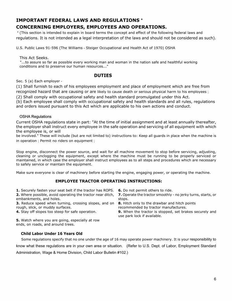
IMPORTANT FEDERAL LAWS AND REGULATIONS* CONCERNING EMPLOYERS, EMPLOYEES AND OPERATIONS. *(This section is intended to explain in board terms the concept and effect of the following federal laws and
regulations. It is not intended as a legal interpretation of the laws and should not be considered as such).
U.S. Public Laws 91-596 (The Williams-Steiger Occupational and Health Act of 1970) OSHA
This Act Seeks. "...to assure so far as possible every working man and woman in the nation safe and healthful working
conditions and to preserve our human resources..."
DUTIES Sec. 5 (a) Each employer-
(1) Shall furnish to each of his employees employment and place of employment which are free from recognized hazard that are causing or are likely to cause death or serious physical harm to his employees;
(2) Shall comply with occupational safety and health standard promulgated under this Act. (b) Each employee shall comply with occupational safety and health standards and all rules, regulations and orders issued pursuant to this Act which are applicable to his own actions and conduct.
OSHA Regulations Current OSHA regulations state in part: "At the time of initial assignment and at least annually thereafter, the employer shall instruct every employee in the safe operation and servicing of all equipment with which the employee is, or will be involved." These will include (but are not limited to) instructions to: Keep all guards in place when the machine is in operation;Permit no riders on equipment;
Stop engine, disconnect the power source, and wait for all machine movement to stop before servicing, adjusting, cleaning or unclogging the equipment, except where the machine must be running to be properly serviced or maintained, in which case the employer shall instruct employees as to all steps and procedures which are necessary to safely service or maintain the equipment.
Make sure everyone is clear of machinery before starting the engine, engaging power, or operating the machine.
EMPLOYEE TRACTOR OPERATING INSTRUCTIONS:
1. Securely fasten your seat belt if the tractor has ROPS. 6. Do not permit others to ride.2. Where possible, avoid operating the tractor near ditch,embankments, and holes.
7. Operate the tractor smoothly - no jerky turns, starts, orstops.
3. Reduce speed when turning, crossing slopes, and onrough, slick, or muddy surfaces.
8. Hitch only to the drawbar and hitch pointsrecommended by tractor manufactures.
4. Stay off slopes too steep for safe operation. 9. When the tractor is stopped, set brakes securely anduse park lock if available.
5. Watch where you are going, especially at rowends, on roads, and around trees.
Child Labor Under 16 Years Old Some regulations specify that no one under the age of 16 may operate power machinery. It is your responsibility to
know what these regulations are in your own area or situation. (Refer to U.S. Dept. of Labor, Employment Standard Administration, Wage & Home Division, Child Labor Bulletin #102.)
7
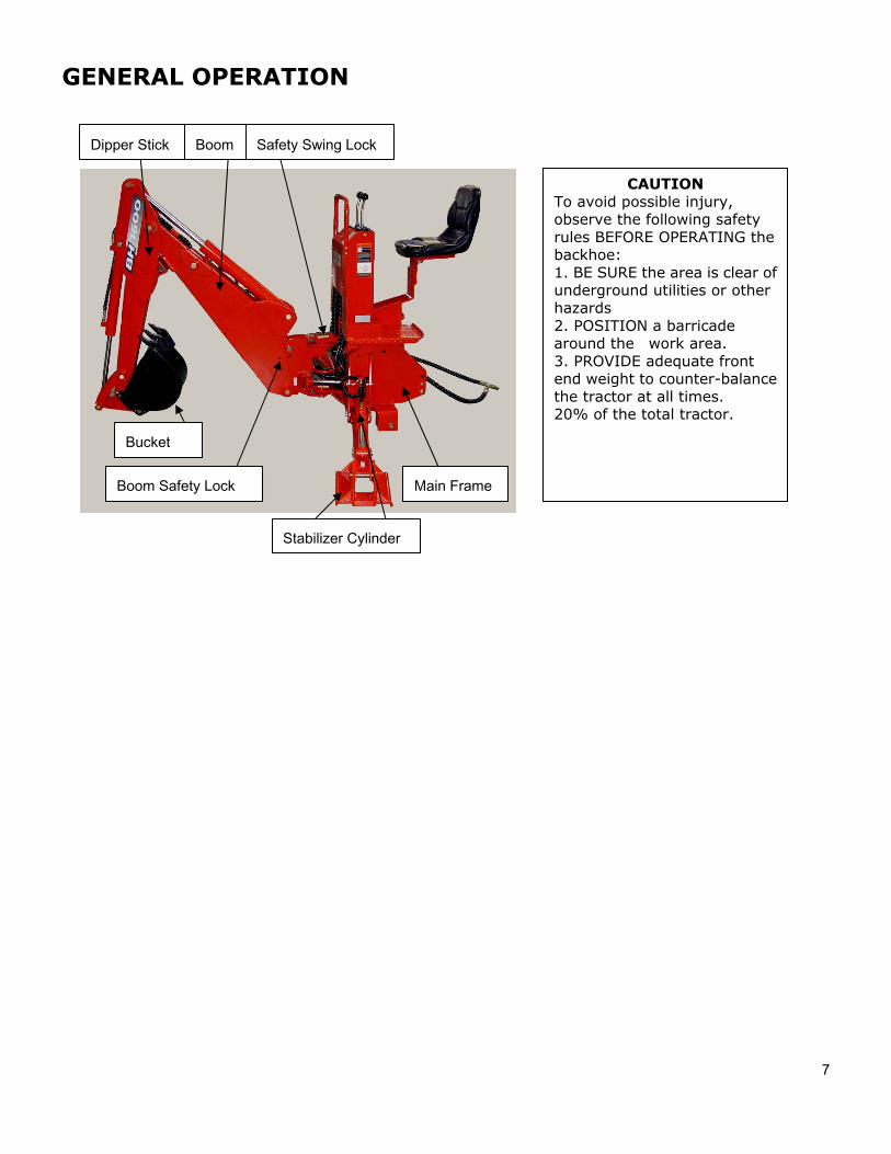
GENERAL OPERATION
Dipper Stick Boom Safety Swing Lock
Boom Safety Lock Main Frame
Stabilizer Cylinder
Bucket
CAUTION To avoid possible injury, observe the following safety rules BEFORE OPERATING the backhoe: 1. BE SURE the area is clear ofunderground utilities or other hazards 2. POSITION a barricadearound the work area. 3. PROVIDE adequate frontend weight to counter-balance the tractor at all times. 20% of the total tractor.
8
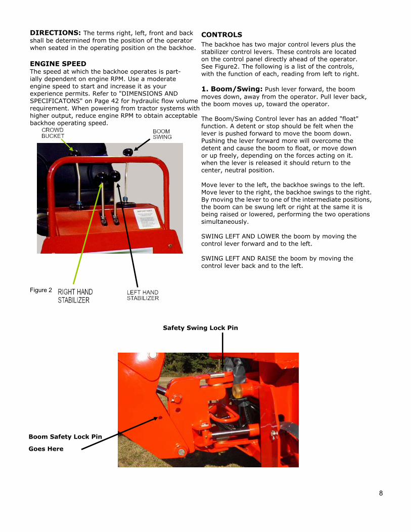
DIRECTIONS: The terms right, left, front and back shall be determined from the position of the operator when seated in the operating position on the backhoe.
ENGINE SPEED The speed at which the backhoe operates is part- ially dependent on engine RPM. Use a moderate engine speed to start and increase it as your experience permits. Refer to "DIMENSIONS AND SPECIFICATONS" on Page 42 for hydraulic flow volume requirement. When powering from tractor systems with higher output, reduce engine RPM to obtain acceptable backhoe operating speed.
Figure 2
CONTROLS The backhoe has two major control levers plus the stabilizer control levers. These controls are located on the control panel directly ahead of the operator. See Figure2. The following is a list of the controls, with the function of each, reading from left to right.
1. Boom/Swing: Push lever forward, the boommoves down, away from the operator. Pull lever back, the boom moves up, toward the operator.
The Boom/Swing Control lever has an added "float" function. A detent or stop should be felt when the lever is pushed forward to move the boom down. Pushing the lever forward more will overcome the detent and cause the boom to float, or move down or up freely, depending on the forces acting on it. when the lever is released it should return to the center, neutral position.
Move lever to the left, the backhoe swings to the left. Move lever to the right, the backhoe swings to the right.By moving the lever to one of the intermediate positions,the boom can be swung left or right at the same it is being raised or lowered, performing the two operations simultaneously.
SWING LEFT AND LOWER the boom by moving the control lever forward and to the left.
SWING LEFT AND RAISE the boom by moving the control lever back and to the left.
Safety Swing Lock Pin
Boom Safety Lock Pin
Goes Here
9
1. SWING RIGHT AND LOWER the boom by movingthe lever forward and to the right.
2. SWING RIGHT AND RAISE the boom by moving thelever forward to the right.
3. Left Hand Stabilizer: Push lever downward, the LHstabilizer lowers. Pull lever upward, the LH stabilizerraises.
4. Right Hand Stabilizer: Push lever downward, theRH stabilizer lowers. Pull lever upward, the RHstabilizer raises.
5. Crowed/Bucket: Push lever forward, the dipperstick moves out, away from the operator. Pull leverback, the dipper stick moves in, toward the operator.
Move lever to left, the bucket curls in. Move lever toright, the bucket extends out.
By moving the lever to one of the intermediate positions, the dipper stick can be extended or retracted at the same time the bucket is being loaded or dumped.
EXTEND AND LOAD the bucket by moving the lever forward and to the left.
RETRACT AND LOAD the bucket by moving the lever back and to the left. EXTEND AND DUMP the bucket by moving the lever forward and to the right.
RETRACT AND DUMP the bucket by moving the lever back and to the right.
The two operations of the room lever, combined with the two operations performed by the bucket and dipper stick control lever, provide four simultaneous operations from the two levers, keeping cycle time to a minimum.
In general, the direction of movement of a control lever corresponds to the movement of the operating member.
Operating the Backhoe
CAUTION
To avoid possible injury, observe the following safety rules WHEN OPERATING the backhoe.
1. DISENGAGE safety locks as shown in Figure 3before attempting to operate the backhoe. Store lock pins in holes provided in operator platform.
2. OPERATE from the backhoe operator's seat only.
3. LOWER the stabilizers until the rear of the tractoris totally supported by them. NOTE: Rear tires should not come up off of the ground. See diagram on Page 11.
4. DO NOT dig near the stabilizers.
5. DO NOT touch overhead wires with any part ofthe backhoe.
6. DO NOT attempt to raise the tractor off theground or move the tractor forward or backward using the backhoe dipper stick or bucket.
7. DO NOT lose stability by swinging the bucketDown hill when positioned on a slope.
8. DO NOT lower the backhoe boom using the"float" function (if equipped). It will freefall, and could result in injury to bystanders or damage to the backhoe.
10
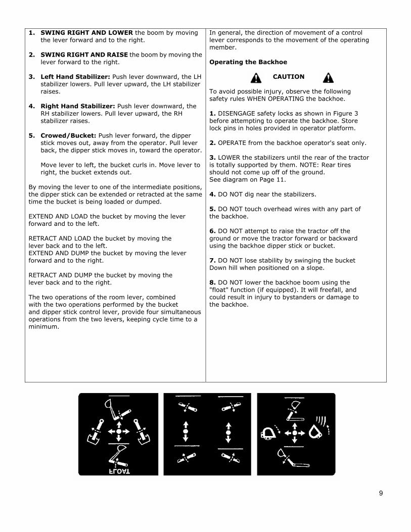
It is not difficult to become an efficient operator. Control lever operating decal is located on back of the control panel. Study this decal. It will assist you in becoming familiar with the controls.
Smooth, light handling of the controls will result in the most efficient backhoe operation.
Operate the backhoe control levers to become familiar with their speed and movements. The engine speed and the size of the hydraulic system will determine the speed of cylinder operation. When powering from tractor systems with higher output than required, reduce engine RPM to obtain acceptable backhoe operating speed.
Swing the boom several times to practice controlling the speed of swing. Do not operate the swing more than 45 each way for the first few times, then gradually increase the arc.
IMPORTANT: To avoid damage to the backhoe, do not slam swing unit into the rubber bumpers.
The boom "float" function (if equipped) may be used during digging to eliminate down pressure when cleaning the bottom of a trench. The primary purpose of the boom "float" function is to protect the operator from serious injury in the event that the backhoe or tractor hitch would fail.
Best results are obtained by digging near the center of the swing arc so material can be dumped on either side.
Best results are obtained by digging near the center of the swing arc so material can be dumped on either side.
As the operator becomes more familiar with the operation of the backhoe, it will be common practice to operate two controls at one time. For ex example, with the bucket extended and the dipper stick extended, the lift control and crowd control can be operated together to bring the bucket toward the operator with down pressure on it. As the dipper stick approaches the operator, the crowd and bucket controls can be operated to close the bucket and trap the material. At the end of the stroke, the lift and crowd controls are operated to move the load up and away from the operator to save time
in clearing the excavation.
This dual operation of controls will speed and simplify the digging operation. Normally the two or more movements will not be equal or even simultaneous, but as the pressure within the cylinders changes, and the resistance on an operating member of the hoe lessens, it will begin to move. It is balancing the force of one member against the other.
NOTE: Actuating the bucket is the key to powerful digging. Operating the crowd and bucket controls simultaneously will insure a full bucket and prevent waste motion and time.
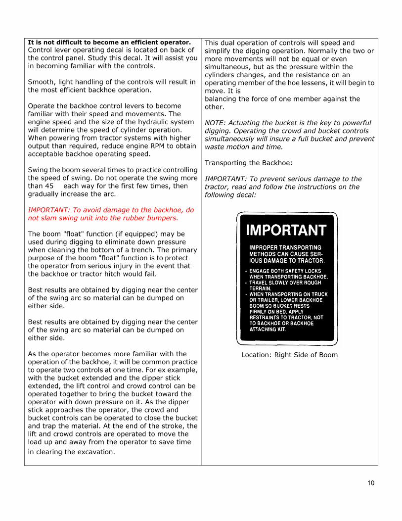
Transporting the Backhoe:
IMPORTANT: To prevent serious damage to the tractor, read and follow the instructions on the following decal:
Location: Right Side of Boom
11
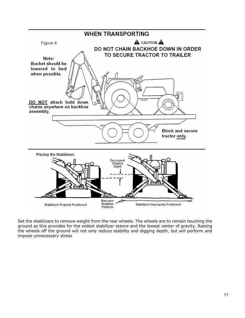
Set the stabilizers to remove weight from the rear wheels. The wheels are to remain touching theground as this provides for the widest stabilizer stance and the lowest center of gravity. Raisingthe wheels off the ground will not only reduce stability and digging depth, but will perform andimpose unnecessary stress
12
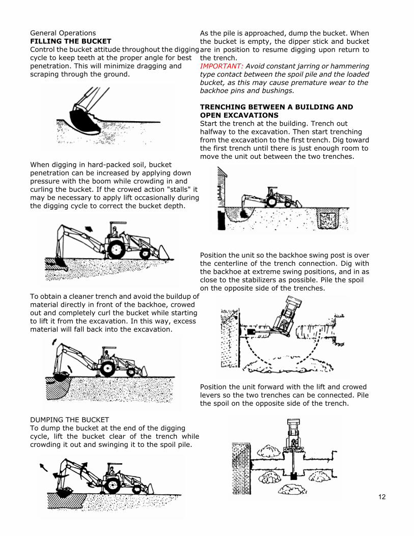
General Operations FILLING THE BUCKET Control the bucket attitude throughout the diggingcycle to keep teeth at the proper angle for best penetration. This will minimize dragging and scraping through the ground.
When digging in hard-packed soil, bucket penetration can be increased by applying down pressure with the boom while crowding in and curling the bucket. If the crowed action "stalls" it may be necessary to apply lift occasionally duringthe digging cycle to correct the bucket depth.
To obtain a cleaner trench and avoid the buildup ofmaterial directly in front of the backhoe, crowed out and completely curl the bucket while starting to lift it from the excavation. In this way, excess material will fall back into the excavation.
DUMPING THE BUCKET To dump the bucket at the end of the digging cycle, lift the bucket clear of the trench whilecrowding it out and swinging it to the spoil pile.
As the pile is approached, dump the bucket. Whenthe bucket is empty, the dipper stick and bucketare in position to resume digging upon return tothe trench. IMPORTANT: Avoid constant jarring or hammeringtype contact between the spoil pile and the loadedbucket, as this may cause premature wear to the backhoe pins and bushings.
TRENCHING BETWEEN A BUILDING AND OPEN EXCAVATIONS Start the trench at the building. Trench out halfway to the excavation. Then start trenching from the excavation to the first trench. Dig towardthe first trench until there is just enough room to move the unit out between the two trenches.
Position the unit so the backhoe swing post is overthe centerline of the trench connection. Dig withthe backhoe at extreme swing positions, and in asclose to the stabilizers as possible. Pile the spoil on the opposite side of the trenches.
Position the unit forward with the lift and crowed levers so the two trenches can be connected. Pilethe spoil on the opposite side of the trench.
13
General Operations SIDE SLOPE EXCAVATING OR TRENCHING Dig with backhoe uphill whenever possible.
Level the backhoe on slops with the stabilizers to dig plumb trenches, or use the backhoe or loader to cut a level slot for the uphill wheel and stabilizer.Pile the spoil from the slot on the low side.
When on the side of a steep slope, cut a levelsurface along the uphill side of the trench with theloader.
Pile the spoil of the cut downhill. When digging, pile the spoil of the trench uphill.
Dig field trenched progressively. As soon as one trench is completed, have the workmen lay the tile.Start the next trench, using the spoil to fill the previous trench.
MISCELLANEOUS When finishing straight walls or bell holes in sandysoil, use a platform under the rear tires and stabilizers. The platform distributes the load over alarger area and lessons the possibility of a cave-in.The platform also tends to keep the unit from creeping rearward if hard digging is encountered.
FINISHING STRAIGHT WALLS Finish the far wall by crowding out while forcing thebucket down from the boom. Actuate the bucket (curl out) to keep the bottom of the bucket vertical.
To finish the near wall, lift up and crowd in. Keep the edges of the bucket horizontal.
BACKFILLING Backfill by lifting the bucket over the spoil pile andthen crowding in. Pull both the crowd and lift leversfor smooth, even backfilling. IMPORTANT: Do not backfill by using the swing circuit and dragging the bucket sideways. Doing socan cause damage to the dipper stick boom swing cylinders or mainframe.
14
Service CAUTION To avoid possible injury, observe the following safety rules WHEN SERVICING the backhoe.
1. ENGAGE safety locks as shown in figure 1 & 3 before servicing the backhoe.
2. DO NOT oil, grease or adjust the backhoe while it is in motion.
3. DO NOT change any backhoe relief valve setting. They are factory set for best performance and safety.
4. ESCAPING FLUID under pressure can have sufficient force to penetrate the skin and cause seriousinjury. Be sure to relieve all pressure before disconnecting lines. Be sure all connections are tight and that lines, pipes and hoses are not damaged before applying pressure to the system.
5. FLUID ESCAPING from a very small hole can be almost invisible. Use a small piece of cardboard orwood not your hands - to search for suspected leaks.
6. SEE A DOCTOR AT ONCE if injured by escaping fluid. Serious infection or gangrene can develop ifproper medical treatment is not administered immediately.
7. PROTECT YOUR EYES - Wear safety glasses. Guard against injury when driving connecting pins orperforming any repair in which particles can chip from work piece or striking tool.
BEGINNING OF SEASON Remove all protective covering. On the PTO pump contained system, maintain the reservoir oil at the proper level by looking at the oil gauge. When checking oil level, the backhoe should be extended to full reach with the bucket rolled back and resting on the ground. All cylinders are retracted except for the boom cylinder. Do not overfill: oil may be forced out of the breather cap. Change PTO Reservoir Hydraulic Oil and Filter every 200hrs, or earlier if neccessary.
Fill Reservoir with: SAE 10W40 engine oil with API “SF/SG” classification in northern climates. AW32
Fill Reservoir with: SAE 40W engine oil with API “SF/SG” classification in southern climates or AW42 Or Reservoir oil should be a all purpose tractor hydraulic oil, or AW32/AW42 is another good choice.
Check hydraulic hoses for deterioration and replace, if necessary.
Lubricate all grease fitting and oil handle linkage. Check hydraulic system for loss of fluid and, if necessary, fill to proper level, or replace it if contaminated. Tighten all loose bolts, nuts and set screw.
Inspect bucket teeth and, if necessary, sharpen or replace them.
Operate the backhoe slowly for a short time before full time operation, to get used to the controls, and also checking for hydraulic leaks, before placing the unit under full load.
Bleeding Backhoe Hydraulic System If the hydraulic hoses have been disconnected from the backhoe or tractor, all trapped air must be
15
removed after the hoses are connected. Start tractor engine and operate backhoe through all movements fully, several times, to purge the system of air.
Hydraulic System Hoses Oil leaks in the pressure side of the system can be located by carefully inspecting the external area of the hoses and fittings.
Check the return side of the system for leaks by examining the oil in the reservoir. If air is being drawn into the system, the oil will contain air bubbles and appear to foam.
When tightening connections, always use two correct size wrenches.
IMPORTANT: Do not over-tighten fittings. Make them just tight enough to eliminate leaks.
NEVER use teflon tape on pipe thread fittings. Always use a paste type sealer.
Hoses on any backhoe are very severely worked and will fail in time. Examine them regularly and replace any that show signs of failure. Pay careful attention to the routing of hoses so they can move fully and freely without kinking, and cannot be pinched or cut by any part of the backhoe.
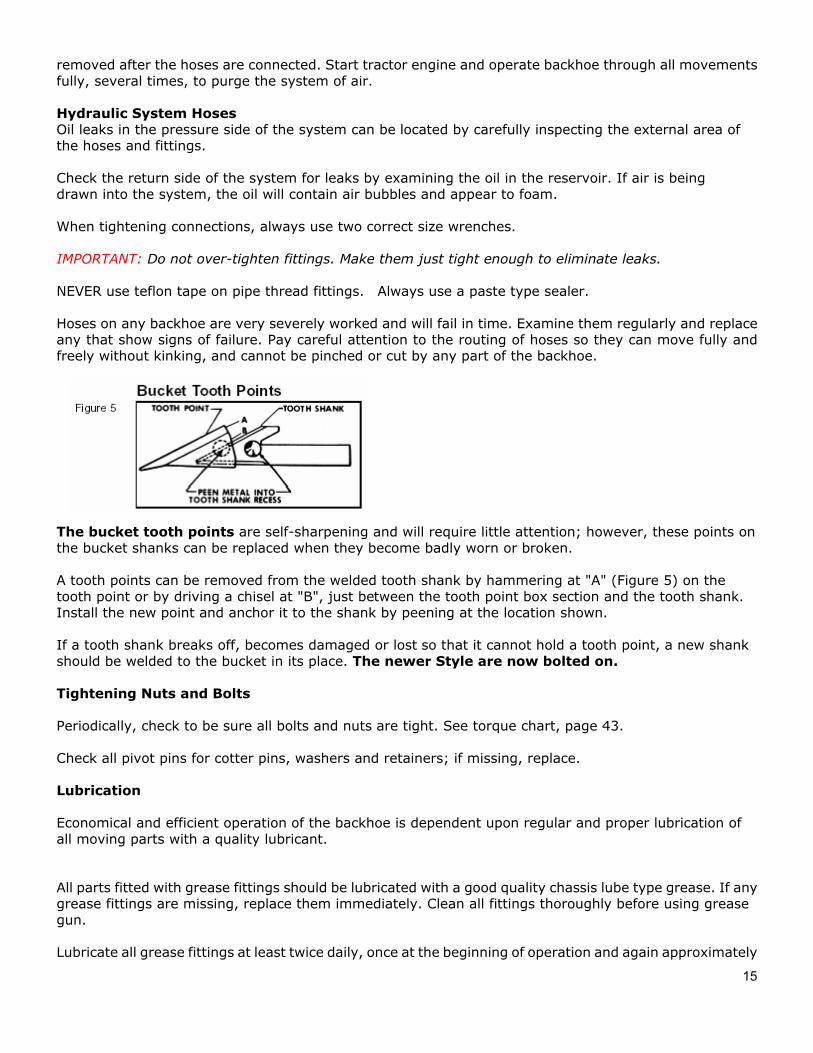
The bucket tooth points are self-sharpening and will require little attention; however, these points on the bucket shanks can be replaced when they become badly worn or broken.
A tooth points can be removed from the welded tooth shank by hammering at "A" (Figure 5) on the tooth point or by driving a chisel at "B", just between the tooth point box section and the tooth shank. Install the new point and anchor it to the shank by peening at the location shown.
If a tooth shank breaks off, becomes damaged or lost so that it cannot hold a tooth point, a new shank should be welded to the bucket in its place. The newer Style are now bolted on.
Tightening Nuts and Bolts
Periodically, check to be sure all bolts and nuts are tight. See torque chart, page 43.
Check all pivot pins for cotter pins, washers and retainers; if missing, replace.
Lubrication
Economical and efficient operation of the backhoe is dependent upon regular and proper lubrication of all moving parts with a quality lubricant.
All parts fitted with grease fittings should be lubricated with a good quality chassis lube type grease. If any grease fittings are missing, replace them immediately. Clean all fittings thoroughly before using grease gun.
Lubricate all grease fittings at least twice daily, once at the beginning of operation and again approximately
16
halfway through the work day.
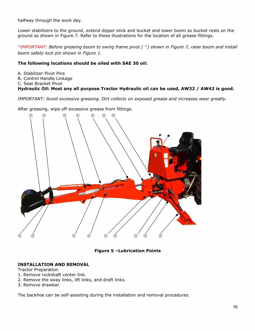
Lower stabilizers to the ground, extend dipper stick and bucket and lower boom so bucket rests on the ground as shown in Figure 7. Refer to these illustrations for the location of all grease fittings.
*IMPORTANT: Before greasing boom to swing frame pivot (*) shown in Figure 7, raise boom and installboom safety lock pin shown in Figure 1.
The following locations should be oiled with SAE 30 oil:
A. Stabilizer Pivot Pins B. Control Handle Linkage C. Seat Bracket Pivot Hydraulic Oil: Most any all purpose Tractor Hydraulic oil can be used, AW32 / AW42 is good.
IMPORTANT: Avoid excessive greasing. Dirt collects on exposed grease and increases wear greatly.
After greasing, wipe off excessive grease from fittings. ① ① ① ① ① ① ①
① ① ① ① ① ① ① ① ①
Figure 5 –Lubrication Points
INSTALLATION AND REMOVAL Tractor Preparation 1. Remove rockshaft center link.2. Remove the sway links, lift links, and draft links.3. Remove drawbar.
The backhoe can be self-assisting during the installation and removal procedures.
17
Installing an Assembled Backhoe on a Tractor
IMPORTANT - Consult the "General Operation" section for proper use and terminology when installing this backhoe.
1. Center sub frame between tractor rear tires and carefully back over sub frame until hydraulic hoses areclose enough to connect.
2. Stop tractor and set park brake.
3. Disconnect tractor pressure line hose from tractor power beyond hose at rear of tractor. Connectbackhoe pressure line hose to tractor pressure line hose. Connect return hose of backhoe to tank line of tractor, located on right hand side of tractor, under rockshaft arm.
DANGER The only time the backhoe should be operated from a position other than the operator's seat is during the backhoe installation and removal process.
• Engage Swing Lock Pin• Always stand away from the backhoe stabilizer legs and along side of the tractor rear tires.
CAUTION Route hydraulic hoses carefully to prevent damage.
4. Start tractor, set throttle at low idle, remove parking brake.
5. Using backhoe hydraulics in the boom and stabilizer leg circuits, raise sub frame enough to alignhooks on sub frame with Tractor lower 3-point hitch connection points. IMPORTANT - As you raise unit, you will need to alternate back and forth between the boom and stabilizer circuits. This procedure is needed to keep the front of the sub frame (under the loader mount) as close to the ground as possible.
6. Roll or drive tractor back until hooks are fully engaged into lower 3-point hitch connection points.
7. Making sure that the Lock Pins and pivoting latches are out of the way in the front of the sub frame,pivot sub frame up into the Loader Mount Weldment. Again, this is accomplished by using the boom hydraulics.
8. Shut off tractor and engage parking brake.
9. Secure pivoting latches using Lock Pins and Hair Pin Clips.
Testing Backhoe Hydraulic Hook-Up 1. Start the tractor.2. Exit the tractor.3. Sitting in the backhoe operator's seat raise and lower the stabilizer legs and extend and retract thedipper stick. 4. Exit backhoe, stop engine, and check hydraulic fluid level in tractor.
Removing Assembled Backhoe from Tractor- 1. Start tractor engine, engage park brake, place throttle in low idle position, and exit tractor.2. Remove Swing Lock Pin from its storage location and install in backhoe.3. Remove Lock Pins and Hair Pins Clips from front of sub frame. Pivot latches forward to disengage fromloader mount.
18
4. Pivot sub frame down until the sub frame clears the Loader Mount Weldment.Again, this is Accomplished by using the boom and stabilizer circuit hydraulics. 5. Flip up pivoting latches and reinstall Lock Pins and Hair Pin Clips for storage Purposes.6. Continuing to use the boom and stabilizer circuit hydraulics, raise sub frame slightly at the Tractorlower 3-point hitch connection points to take the sub frame weight off of the pins.
IMPORTANT - Watch that hydraulic hoses to backhoe are not kinked or pulled tight. 7. Drive tractor ahead just enough (5" to 6") to clear sub frame hooks from the Tractor lower 3-point hitchconnection points.
8. Again, using boom and stabilizer circuit hydraulics lower backhoe and sub frame to the ground.
9. Shut off tractor, engage parking brake, then disconnect hydraulic hoses from backhoe.10. Reconnect tractor pressure line hose to tractor power beyond hose, located just above PTO mastershield.
NOTE: For long term storage, coat exposed cylinder rods with grease.
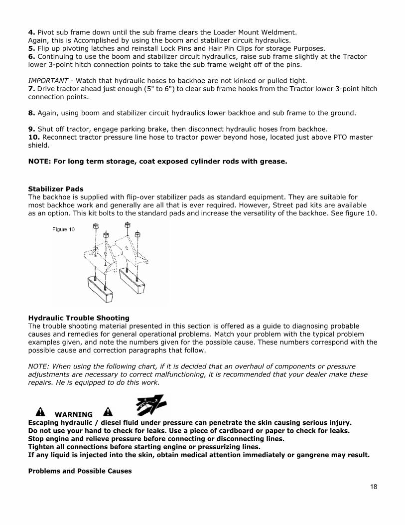
Stabilizer Pads The backhoe is supplied with flip-over stabilizer pads as standard equipment. They are suitable for most backhoe work and generally are all that is ever required. However, Street pad kits are available as an option. This kit bolts to the standard pads and increase the versatility of the backhoe. See figure 10.
Hydraulic Trouble Shooting The trouble shooting material presented in this section is offered as a guide to diagnosing probable causes and remedies for general operational problems. Match your problem with the typical problem examples given, and note the numbers given for the possible cause. These numbers correspond with the possible cause and correction paragraphs that follow.
NOTE: When using the following chart, if it is decided that an overhaul of components or pressure adjustments are necessary to correct malfunctioning, it is recommended that your dealer make these repairs. He is equipped to do this work.
WARNING Escaping hydraulic / diesel fluid under pressure can penetrate the skin causing serious injury. Do not use your hand to check for leaks. Use a piece of cardboard or paper to check for leaks. Stop engine and relieve pressure before connecting or disconnecting lines. Tighten all connections before starting engine or pressurizing lines. If any liquid is injected into the skin, obtain medical attention immediately or gangrene may result.
Problems and Possible Causes
19
1. Machine fails to operate when started initially -1, 2, 5, 7, 16, 242. Machine loses power after operating satisfactory initially - 1, 8, 10, 14, 16, 243. Loss of power in lift or crowd cylinder, but other cylinders function properly - 23, 25, 30
Problems and Possible Causes, Continued4. Loss of power in any one cylinder including lift and crowd - 8, 9, 10, 11, 12, 13, 23, 25, 265. Loss of power in swing cylinders, but other cylinders functioning property - 8, 9, 10, 11, 12, 13, 23, 24,
26 6. Maximum swing action cannot be obtained - 12, 15.7. Slow operation of machine (lack of power) all cylinders - 1, 4, 6, 14, 16, 248. Spongy or jerking action of cylinders and/or noisy operation - 1, 3, 4, 59. Lift, crowd or bucket cylinders drop under load when control spools shifted from neutral - 28, 3010. Load drops or settles - 8, 10, 13, 26, 2811. Leaky cylinders - 10, 11, 12, 1312. Leaky valve - 8, 16, 17, 2913. Sticky valve spool - 17, 20, 21, 2214. Unable to push valve spool in - 17, 18, 20, 21, 2215. Spring centered spools do not return to neutral- 17, 18, 19, 20, 21, 22
Causes and Corrections 1. Low oil supply in reservoir - fill to proper level.
2. No oil supply to machine - oil is not being diverted from the prime mover hydraulic system.Be sure that the proper controls are actuated on the prime mover.
3. Air in system - bleed all circuits of air by operating machine at maximum oil flow and throughfull movements.
4. Oil viscosity too heavy, or oil is not at operating temperature - use recommended hydraulic fluid.Run machine until oil reaches operating temperature.
5. Pump not running - check pump drive to be sure it is engaged.
6. Insufficient pumping - advance engine throttle.
7. Improper hose connection - IMPORTANT: Be sure inlet and return hoses are hooked up correctly Improper hook-up will result in damage to the backhoe valve.
8. Loose oil line connections, leaks in line or broken lines - tighten all hose connections and replace anddamaged O-ring at leaking O-ring fittings. Check and replace any damaged hoses and lines.
9. Restrictions in oil line - check and replace any damaged hoses and lines. Check for pinched hoses.
10. Oil is bypassing cylinder piston, scored piston, worn piston packing, or defective piston assemblyreplace or rebuild the cylinder; replace damaged parts.
11. Scored piston rods and worn rod guides in cylinder - replace or rebuild the cylinder; replace damagedparts.
12. Bent piston rod in cylinder - replace or rebuild the cylinder; replace damaged parts.
13. Worn or damaged rod seals on cylinder; external repack cylinder. Rebuild cylinder, replacing damagedparts as necessary.
14. Diverter valve on prime mover leaking externally or bypassing oil internally through valve to reservoir
20
diverter valve may need rebuilding or replacing.
15. Something jamming the swing linkage – remove interference.
16. Excessive back pressure - relief condition. May be restriction from outlet to reservoir.
17. Paint on valve spool; sticking valve spool or scored valve spool - clean valve spool. Binding is usuallycaused from an over tightened plug, mounting bolt, fitting in valve body or tie rod bolt. If a plug or fitting in the valve body is leaking, do not over tighten in an effort to stop leak. This will distort body casting and cause spools to bind. Instead, the plug and fitting should be removed from valve body and be reconnected, using a new O-ring. Do not apply excessive pressure on mounting bolts. The rods should be torqued to 20 ft./lbs. Never force spool, if binding occurs see item 30 at the end.
18. Oil leakage past spool seal into spool cap remove cap. If it contains oil replace spool seal O-rings.Check O-ring retainer to be sure it is flat. If it has been "belled" check for restriction from outlet to reservoir of valve which would cause excessive back pressure. See item 30 at the end and item 9.
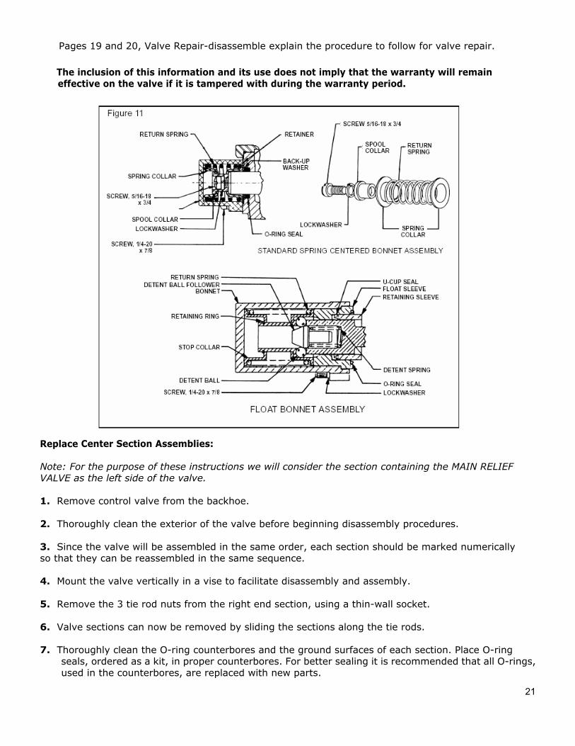
19. Broken return springs - replace springs, see item 30 at the end and Figure 11.
20. Bent spool - replace with new spool section. See item 30 at the end.
21. Foreign particles - clean system and valve.
22. Misalignment of control handle linkage – check linkage for binding condition.
23. Spool not moved to full stroke - check travel, should be 5/16" either way, or a total of 5/8".See item 30 at the end.
24. Relief valve setting in backhoe control valve too low or defective - relief pressure will have tobe checked and corrections made. Backhoe system pressure is 2100 psi. Relief valve mayneed cleaning and overhauling, or entire cartridge must be replaced. See item 30 at the end.
25. Overload relief valve in the control valve stuck open or malfunctioning - clean relief carefullybut do not disturb its pressure setting as it cannot be field calibrated, or replace cartridge.See item 30 at the end.
26. Worn control valve - replace the control valve.
27. Check proper in the control valve not holding clean check poppet(s) carefully, being sure that it movesfreely with good spring action and seats properly or replace. See item 30 at the end.
28. Damaged or worn spool seals - replace spool end seals, see item 30 at the end.
29. Ball in check valve is stuck or not seating properly - clean anti-cavitation valve carefully, being sure
that checks move freely and seat properly, or replace cartridge. See item 30 next.
30. Problems involving the control valve proper:This valve is a precision device and is not intended for any extensive field adjustment or repair. Fieldreplacement parts are limited to seal kits, cartridges, valve sections and tie rods. Replacement ofthese parts, the opening of check cavities and certain relief valve cavities to examine for trapped dirt,or the resetting of the main relief valve with the use of good pressure gauge, should be referred toqualified service personnel.Dirt and shreds of packing material are the usual causes of valve malfunction. Be sure the reservoir oilsupply is kept clean and only factory supplied packings are used in cylinder repair. Everything must beclean and free of dirt during the oil line removal and replacement, and during any cylinder work.
21
Pages 19 and 20, Valve Repair-disassemble explain the procedure to follow for valve repair.
The inclusion of this information and its use does not imply that the warranty will remain effective on the valve if it is tampered with during the warranty period.
Replace Center Section Assemblies:
Note: For the purpose of these instructions we will consider the section containing the MAIN RELIEF VALVE as the left side of the valve.
1. Remove control valve from the backhoe.
2. Thoroughly clean the exterior of the valve before beginning disassembly procedures.
3. Since the valve will be assembled in the same order, each section should be marked numericallyso that they can be reassembled in the same sequence.
4. Mount the valve vertically in a vise to facilitate disassembly and assembly.
5. Remove the 3 tie rod nuts from the right end section, using a thin-wall socket.
6. Valve sections can now be removed by sliding the sections along the tie rods.
7. Thoroughly clean the O-ring counterbores and the ground surfaces of each section. Place O-ringseals, ordered as a kit, in proper counterbores. For better sealing it is recommended that all O-rings, used in the counterbores, are replaced with new parts.
22
8. Replace the sections on tie rods with the O-ring counterbores facing the right end of the valve. Becareful replacing the sections so that the section O-rings are not moved from the counterbores.
9. When all sections are assembled on the tie rods, tighten the tie rod nuts equally to 20 ft. lbs . torque,NO MORE - NO LESS, or spool may bind and stick.
Replacing Spool Seals:
Note: For the purpose of these instructions we will consider the control handle side of the valve as the
FRONT, and the opposite side as the BACK. 1. Remove control valve from the backhoe.
2. Thoroughly clean the exterior of the valve before beginning disassembly procedures.
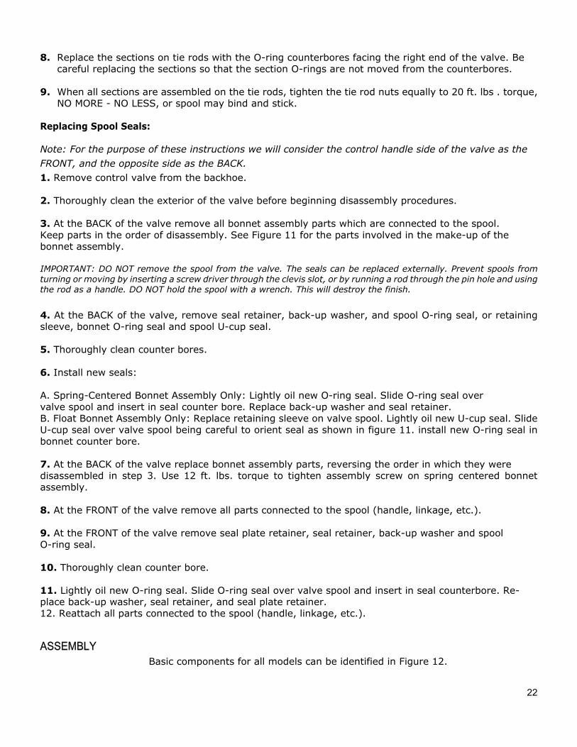
3. At the BACK of the valve remove all bonnet assembly parts which are connected to the spool.Keep parts in the order of disassembly. See Figure 11 for the parts involved in the make-up of the bonnet assembly.
IMPORTANT: DO NOT remove the spool from the valve. The seals can be replaced externally. Prevent spools from turning or moving by inserting a screw driver through the clevis slot, or by running a rod through the pin hole and using the rod as a handle. DO NOT hold the spool with a wrench. This will destroy the finish.
4. At the BACK of the valve, remove seal retainer, back-up washer, and spool O-ring seal, or retainingsleeve, bonnet O-ring seal and spool U-cup seal.
5. Thoroughly clean counter bores.
6. Install new seals:
A. Spring-Centered Bonnet Assembly Only: Lightly oil new O-ring seal. Slide O-ring seal over valve spool and insert in seal counter bore. Replace back-up washer and seal retainer. B. Float Bonnet Assembly Only: Replace retaining sleeve on valve spool. Lightly oil new U-cup seal. Slide U-cup seal over valve spool being careful to orient seal as shown in figure 11. install new O-ring seal in bonnet counter bore.
7. At the BACK of the valve replace bonnet assembly parts, reversing the order in which they weredisassembled in step 3. Use 12 ft. lbs. torque to tighten assembly screw on spring centered bonnet assembly.
8. At the FRONT of the valve remove all parts connected to the spool (handle, linkage, etc.).
9. At the FRONT of the valve remove seal plate retainer, seal retainer, back-up washer and spoolO-ring seal.
10. Thoroughly clean counter bore.
11. Lightly oil new O-ring seal. Slide O-ring seal over valve spool and insert in seal counterbore. Re- place back-up washer, seal retainer, and seal plate retainer. 12. Reattach all parts connected to the spool (handle, linkage, etc.).
ASSEMBLY Basic components for all models can be identified in Figure 12.
23
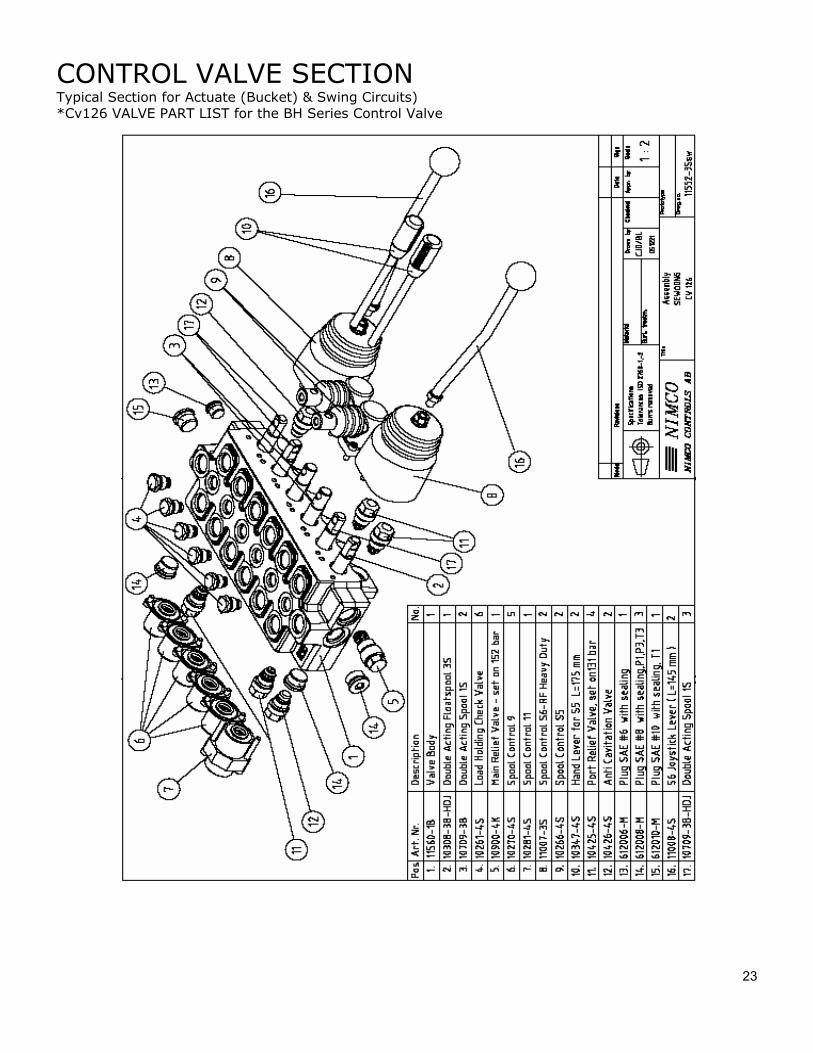
CONTROL VALVE SECTION Typical Section for Actuate (Bucket) & Swing Circuits) *Cv126 VALVE PART LIST for the BH Series Control Valve
24
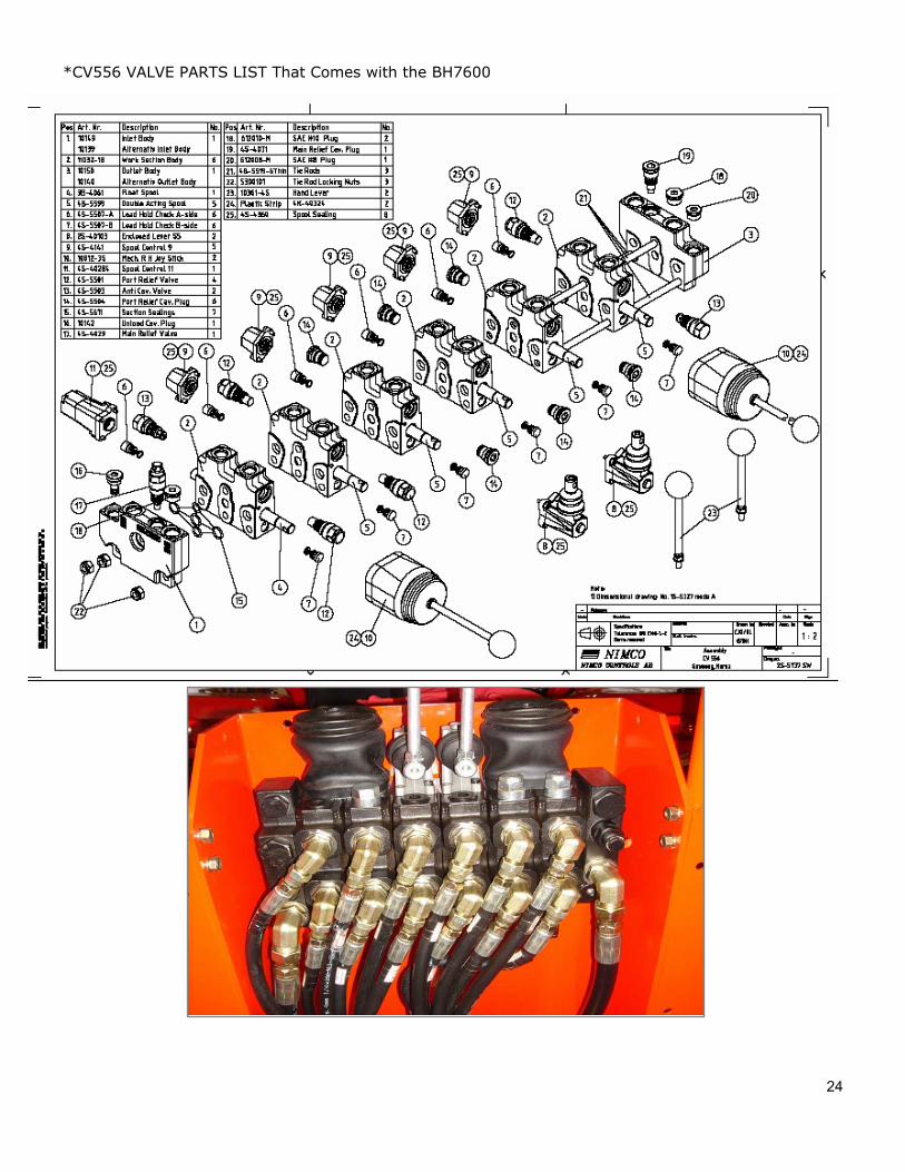
*CV556 VALVE PARTS LIST That Comes with the BH7600
25
General Unpacking The backhoe has been partially disassembled and strapped to a skid for shipping purposes. Initial installation on the tractor will require a hoist or other device capable of safely lifting the entire backhoe from the skid. After the initial installation is complete, the backhoe can serve as its own erecting hoist, by lowering stabilizers and bucket to the ground. Additional lifting devices will not be required for normal removal and reattaching.
Assembly - Figure 12 IMPORTANT: Tighten all hardware to torque requirements specified in torque chart.
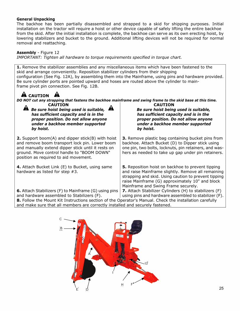
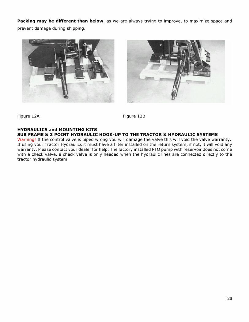
1. Remove the stabilizer assemblies and any miscellaneous items which have been fastened to theskid and arrange conveniently. Reposition stabilizer cylinders from their shipping configuration (See Fig. 12A), by assembling them into the Mainframe, using pins and hardware provided. Be sure cylinder ports are pointed upward and hoses are routed above the cylinder to main- frame pivot pin connection. See Fig. 12B.
CAUTION DO NOT cut any strapping that fastens the backhoe mainframe and swing frame to the skid base at this time.
CAUTION Be sure hoist being used is suitable,
has sufficient capacity and is in the proper position. Do not allow anyone under a backhoe member supported by hoist.
CAUTION Be sure hoist being used is suitable,
has sufficient capacity and is in the proper position. Do not allow anyone under a backhoe member supported by hoist.
2. Support boom(A) and dipper stick(B) with hoistand remove boom transport lock pin. Lower boom and manually extend dipper stick until it rests on ground. Move control handle to "BOOM DOWN" position as required to aid movement.
3. Remove plastic bag containing bucket pins frombackhoe. Attach Bucket (D) to Dipper stick using one pin, two bolts, locknuts, pin retainers, and was- hers as needed to take up gap under pin retainers.
4. Attach Bucket Link (E) to Bucket, using samehardware as listed for step #3.
5. Reposition hoist on backhoe to prevent tippingand raise Mainframe slightly. Remove all remaining strapping and skid. Using caution to prevent tipping raise Mainframe (G) approximately 10" and block Mainframe and Swing Frame securely.
6. Attach Stabilizers (F) to Mainframe (G) using pinsand hardware assembled to Stabilizers (F).
7. Attach Stabilizer Cylinders (H) to stabilizers (F)using pins and hardware assembled to stabilizer (F).
8. Follow the Mount Kit Instructions section of the Operator's Manual. Check the installation carefullyand make sure that all members are correctly installed and securely fastened.
26
Packing may be different than below, as we are always trying to improve, to maximize space and
prevent damage during shipping.
Figure 12A Figure 12B
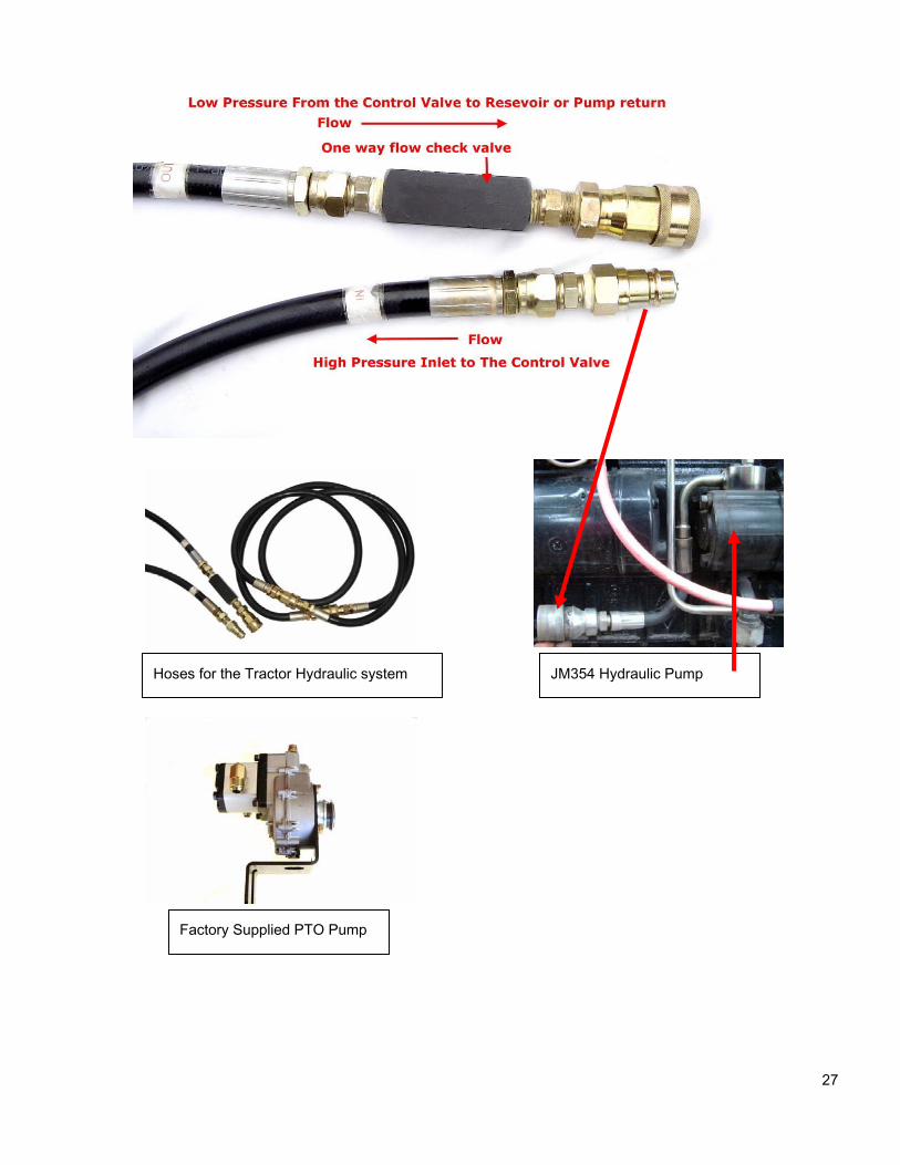
HYDRAULICS and MOUNTING KITS SUB FRAME & 3 POINT HYDRAULIC HOOK-UP TO THE TRACTOR & HYDRAULIC SYSTEMS Warning! If the control valve is piped wrong you will damage the valve this will void the valve warranty. If using your Tractor Hydraulics it must have a filter installed on the return system, if not, it will void any warranty. Please contact your dealer for help. The factory installed PTO pump with reservoir does not come with a check valve, a check valve is only needed when the hydraulic lines are connected directly to the tractor hydraulic system.
27
JM354 Hydraulic Pump Hoses for the Tractor Hydraulic system
Factory Supplied PTO Pump
28
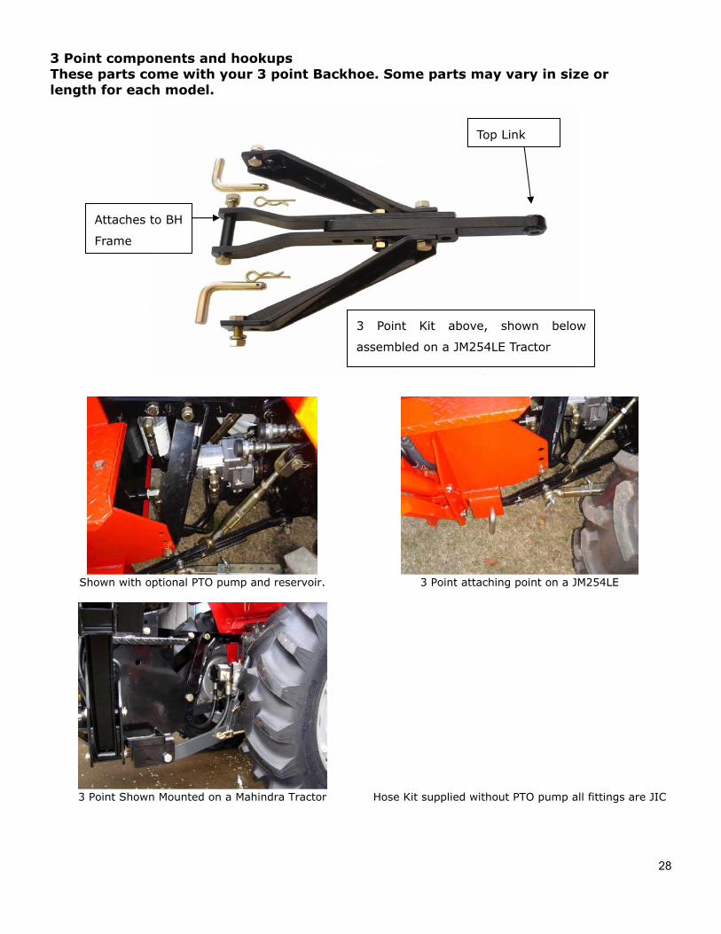
3 Point components and hookups These parts come with your 3 point Backhoe. Some parts may vary in size or length for each model.
Shown with optional PTO pump and reservoir. 3 Point attaching point on a JM254LE
3 Point Shown Mounted on a Mahindra Tractor Hose Kit supplied without PTO pump all fittings are JIC
Top Link
Attaches to BH
Frame
3 Point Kit above, shown below
assembled on a JM254LE Tractor
29
ATTACHING KIT INSTRUCTIONS 3-POINT HITCH LINKAGE & MOUNT KIT & HYDRAULIC HOOK-UP
General Description Mounting and hydraulics kits include two hoses which Can be used to connect the backhoe to the tractor hydraulic system. Additional hydraulic com-ponents or kits will be required to complete the hook-up to the tractor hydraulic system. Refer to the Hydraulic Hook-up section for futher information. Pumps and reservoir kits are available as options.
The backhoe is mounted on the tractor lower link arms and an adjustable upper link. A set of stabilizer arms is included. They bolt from the adjustable upper link to the backhoe mainframe, locking the hoe rigidly in one position. IMPORTANT: Tractor lower links must be kept free of lifting forces at all times after installation of the attaching kit, by keeping tractor quadrant lever in the lowered position.
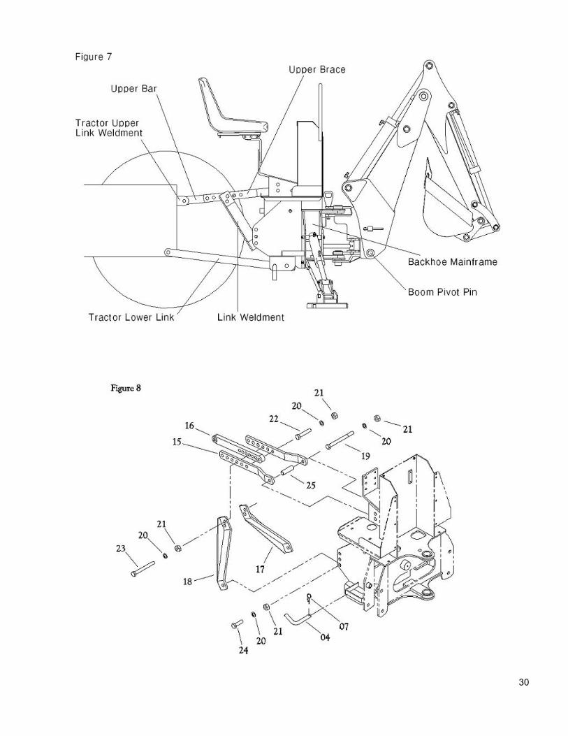
IMPORTANT: If the 3-point kit is to be used with a PTO & Reservoir Kit, the Reservoir Tank and it’s fittings should be installed before proceeding with the 3-Point installation, this might be done at the factory depending on how purchased. 3-POINT HITCH LINKAGE ASSEMBLY (Refer to Figures 7, 8 below, page 30 )
IMPORTANT: Tighten all hardware to the torque requirements specified in the torque chart.
WARNING
To prevent bodily injury, do not operate backhoe unless Lower Link Weldments(17,18) are properly installed and adjusted. Failure to do so may result in backhoe being thrust upward, crushing operator against cab or ROPS.
1. Use hoist to raise the backhoe mainframe so that the boom pivot pin is approximately12”(BH6600), or14” (BH7600), off the ground.
2. Back tractor close to the backhoe. Connect tractor lower link arms to lower link mounts at position “C”Figure 8, using two L-pins(4), two cotter pins, and two snap pins (7) as shown in Figure 8.
3. Secure upper bar(16) between upper braces(15) Using M20*2.5p*90 bolt(22), lock washer(20) Andnut(21).Use hoist to raise or lower backhoe slightly until a hole in the upper bar aligns with a hole in the upper braces. 4. Attach RH lower link weldment(18) and LH lower link weldment(17) to backhoe mainframe usingM20*2.5p*50 bolt(24), lockwasher(20), and nut(21).
5. Align RH and LH link weldment(17,18) with a hole in the upper bar/brace assembly, as close to the tractoras possible. Use M20*2.5p*110 bolt(23), lockwashers(20) and nut(21). You may need to return to Step 4 and readjust upward or downward the bolt connection.
6. Remove backhoe from the tractor.
7. Tighten all hardware at this time. Check your installation very carefully to be sure all members arecorrectly installed and securely fastened.
7A. If using optional PTO pump and Reservoir Kit proceed to that section prior to remounting the backhoe onto the tractor.
8. Connect hoses from the backhoe control valve to the tractor hydraulic system as described in “Hydraulichook-up.” Section, prior to remounting the backhoe onto the tractor.
30
34
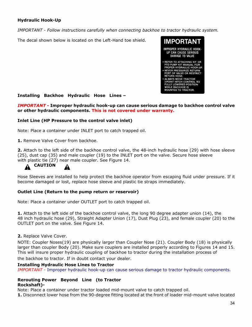
Hydraulic Hook-Up
IMPORTANT - Follow instructions carefully when connecting backhoe to tractor hydraulic system.
The decal shown below is located on the Left-Hand toe shield.
Installing Backhoe Hydraulic Hose Lines –
IMPORTANT - Improper hydraulic hook-up can cause serious damage to backhoe control valve or other hydraulic components. This is not covered under warranty.
Inlet Line (HP Pressure to the control valve inlet)
Note: Place a container under INLET port to catch trapped oil.
1. Remove Valve Cover from backhoe.
2. Attach to the left side of the backhoe control valve, the 48-inch hydraulic hose (29) with hose sleeve(25), dust cap (35) and male coupler (19) to the INLET port on the valve. Secure hose sleeve with plastic tie (27) near male coupler. See Figure 14.
CAUTION
Hose Sleeves are installed to help protect the backhoe operator from escaping fluid under pressure. If it become damaged or lost, replace hose sleeve and plastic tie straps immediately.
Outlet Line (Return to the pump return or reservoir)
Note: Place a container under OUTLET port to catch trapped oil.
1. Attach to the left side of the backhoe control valve, the long 90 degree adapter union (14), the48 inch hydraulic hose (29), Straight Adapter Union (17), Dust Plug (23), and female coupler (20) to the OUTLET port on the valve. See Figure 14.
2. Replace Valve Cover.NOTE: Coupler Noses(19) are physically larger than Coupler Nose (21). Coupler Body (18) is physically larger than coupler Body (20). Make sure couplers are installed properly according to Figures 14 and 15. This will insure proper hydraulic coupling of backhoe to tractor during the installation process of the backhoe to tractor. If in doubt contact your dealer. Installing Hydraulic Hose Lines to Tractor IMPORTANT - Improper hydraulic hook-up can cause serious damage to tractor hydraulic components.
Rerouting Power Beyond Line (to Tractor Rockshaft)- Note: Place a container under tractor loaded mid-mount valve to catch trapped oil. 1. Disconnect lower hose from the 90-degree fitting located at the front of loader mid-mount valve located
35
on the right hand side of the tractor. See Figure 15. 2. Reroute hose back under the center of the tractor. Direct it rearward on the left hand side, to theback of the tractor and lay it over the top of the left hand rear axle casting. Make sure that hose does not interfere with any lines or operational linkages. 3. Install Hose Sleeve (28), Straight Adapter Union(13), and Male Coupler (19) to hose. Secure hosesleeve with plastic tie (27) near male coupler. SeeFigure 15. 4. Using heavy-duty plastic tie (26) secure hose assembly to area near top of PTO shield.
CAUTION Hose Sleeves are installed to help protect the backhoe operator from escaping fluid under pressure. If it becomes damaged or lost, replace hose sleeve and plastic tie straps immediately.
Loader Valve Tank Port Line (Return) 1. Disconnect hydraulic hose from right hand side of rockshaft housing. Hose is located just below righthand rockshaft arm. 2. Install Tee Fitting (16), Straight Adapter Union on right hand side of rockshaft housing. See Figure 15.3. Reconnect and tighten hydraulic hose that was removed in step 1.
Loader Valve Pressure Line (from loader power beyond port) 1. Install the 86-inch hydraulic hose (30) to the 90-degree fitting located at the front of loader midmountvalve located on the right hand side of the tractor. See Figure 15. 2. Route hose back under along the right hand side of the tractor. Direct it rearward on the right handside, to the back of the tractor and lay it over the top of the right hand rear axle casting. Make sure that hose does not interfere with any lines or operational linkages. Secure hose along its route with two heavy-duty plastic ties (26). 3. Install Hose Sleeve (28), Plastic Tag (31), 90-degree Adapter Union (15), and Female Coupler (18) tohose. Secure hose sleeve with plastic tie (27) near adapter union. See Figure 15. 4. Make sure that all hydraulic connections made to the tractor are tight and leak free.
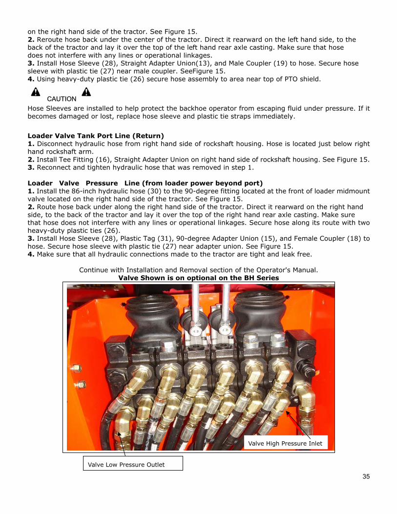
Continue with Installation and Removal section of the Operator's Manual. Valve Shown is on optional on the BH Series
Valve High Pressure Inlet
Valve Low Pressure Outlet
36
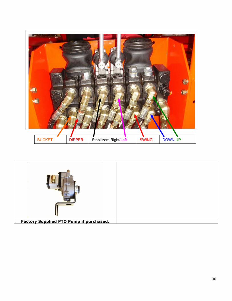
Factory Supplied PTO Pump if purchased.
DOWN UP DIPPER SWING BUCKET Stabilizers Right/Left

38
TORQUE VALVES Common bolts and nuts--Tightening Torque Plus/Minus 20%
Size Grade 2 Grade 5 Grade 8
1/4-20 NC 70 in. lbs. 115 in. lbs. 165 in. lbs.
1/4-28 NF 85 in. lbs. 140 in. lbs. 200 in. lbs.
5/16-18 NC 150 in. lbs. 250 in. lbs. 350 in. lbs.
5/16-24 NF 165 in. lbs. 270 in. lbs. 30 ft. lbs.
3/8-16 NC 260 in. lbs. 35 ft. lbs. 50 ft. lbs.
3/8-24 NF 300 in. lbs. 40 ft. lbs. 60 ft. lbs.
7/16-14 NC 35 ft. lbs. 55 ft. lbs. 80 ft. lbs.
7/16-20 NF 45 ft. lbs. 75 ft. lbs. 105 ft. lbs.
1/2-13 NC 50 ft. lbs 80 ft. lbs. 115 ft. lbs.
1/2-20 NF 70 ft. lbs. 105 ft. lbs. 165 ft. lbs.
9/16-12 NC 75 ft. lbs. 125 ft. lbs. 175 ft. lbs.
9/16-18 NF 100 ft. lbs. 165 ft. lbs. 230 ft. lbs.
5/8-11 NC 110 ft. lbs. 180 ft. lbs. 260 ft. lbs.
5/8-18 NF 140 ft. lbs. 230 ft. lbs. 330 ft. lbs.
3/4-10 NC 150 ft. lbs. 245 ft. lbs. 350 ft. lbs.
3/4-16 NF 200 ft. lbs. 325 ft. lbs. 470 ft. lbs.
Note - See tractor instruction manual or your tractor dealer for tightening of metric bolts.

39
SERVICE NOTES: _________________________________________________________________________________________________________________________________________________________________________________________________________________________________________________________________________________________________________________________________________________________________________________________________________________________________________________________________________________________________________________________________________________________________________________________________________________________________________________________________________________________________________________________________________________________________________________________________________________________________________________________________________________________________________________________________________________________________________________________________________________________________________________________________________________________________________________________________________________________________________________________________________________________________________________________________________________________________________________________________________________________________________________________________________________________________________________________________________________________________________________________________________________________________________________________________________________________________________________________________________________________________________________________________________________________________________________________________________________________________________________________________________________________________________________________________________________________________________________________________________________________________________________________________________________________________________________________________________________
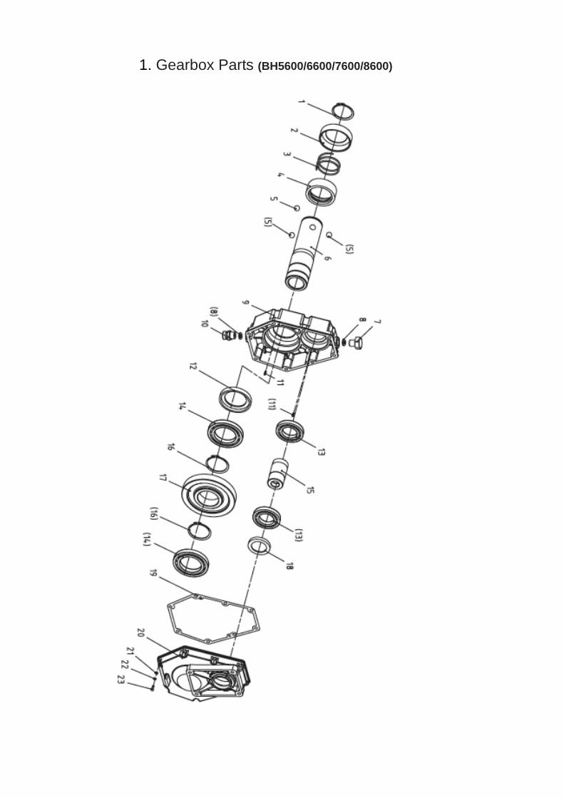
1. Gearbox Parts (BH5600/6600/7600/8600)

1. Parts list
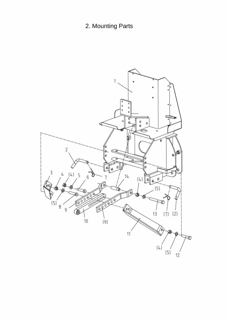
2. Mounting Parts

2. Mounting Parts
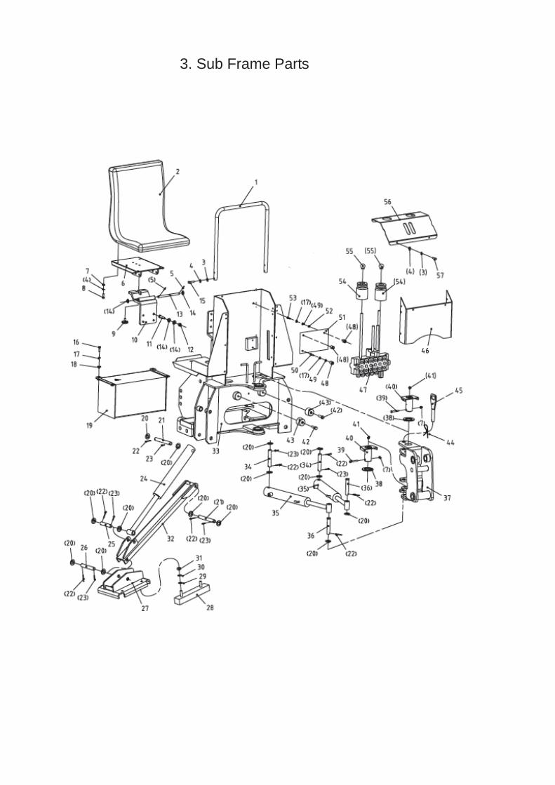
3. Sub Frame Parts

3. Sub Frame Parts

3. Sub Frame Parts
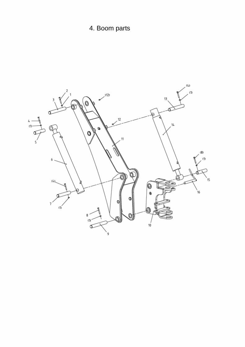
4. Boom parts

4. Boom parts
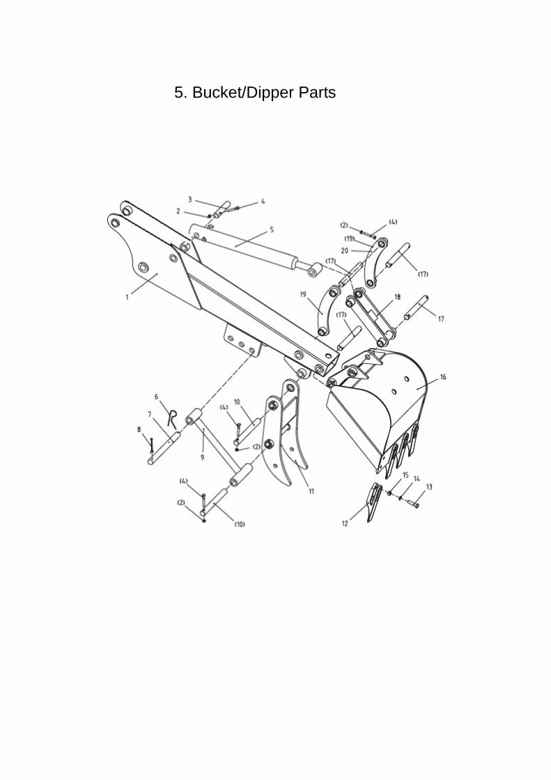
5. Bucket/Dipper Parts

5. Bucket/Dipper Parts
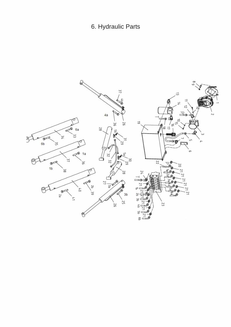
6. Hydraulic Parts

6. Hydraulic Parts

6. Hydraulic Parts
BH HORNET SERIES BACKHOE LIMITED WARRANTY
Section1.00 Coverage:
The Manufacturer & Seller warrants the backhoe for one year (365 days) from purchase date to the original non-commercial, industrial, governmental, or municipal purchaser to be free from major defects in manufacturing and materials. Manufacturer will provide PARTS AND OR LABOR for warranty parts found, upon examination at its designated facility to be defective under normal use and service. LABOR IS ONLY COVERED IF THE UNIT IS RETURNED TO THE ORIGINAL DEALER OR AN AUTHORIZED DEALER FOR SERVICE. ALL OTHER PARTS INCLUDING CONSUMABLE & EXPENDABLE ITEMS (HOSES, PINS, SHIELDS, SEALS, GUARDS, ETC.) AND NORMAL MAINTENANCE ITEMS (WELDS, LUBRICANTS, ETC.) ARE NOT COVERED BY THIS WARRANTY. NOTE: Expendable or normal maintenance items found to be defective within 7 days of delivery will be repaired or replaced free of charge by the seller.
This warranty does not apply to any part of the BACKHOE which has been subjected to improper or abnormal use, negligence, alteration, modification, improper assembly, accident, damage due to lack of maintenance or use of wrong oil, or lubricants, or which has served its normal life. Misuse or abuse including, but not limited to, not following the maintenance schedule and or operating the backhoe without lubricants, improper installation or alteration shall invalidate this warranty and cause it to be canceled. The Manufacturer, the Importer, the Distributor and the Seller makes no representations or warranties of any kind, express or implied, (including but not limited to implied warranties of merchantability and fitness for a particular purpose) other than those contained on the front and back hereon.
Model: Date of Sale:
Owner Name: Owner Address:
City: ST: Zip Code: Seller (business): The Tractor Man
Acceptance of responsibility:
I (Purchaser) have read, or the complete warranty and instructions have been read to me, and I understand this warranty does NOT COVER ANY LABOR COSTS and that all disputes will be settled by binding arbitration. I have reviewed and received the following items from my salesperson. I have had all questions answered and understand that I alone am responsible for proper maintenance and safe operation of this Backhoe and/or goods.
_____ Lubrication Requirements _____ Maintenance Schedule
I (purchaser) also understand that persons not familiar with the operation of this equipment should not be allowed to use it. Children especially should not operate or be near equipment.
Owners Signature: x ______________________________________________________ Date: ______________________________
FOR WARRANTY TO REMAIN VALID, SELLER OR QUALIFIED SERVICE PERSON MUST PREFORM A 50-HOUR SERVICE ON THIS BACKHOE. PROOF OF THIS SERVICE IS TO BE PROVIDED IF REQUESTED.
2.01. Your warranty is activated upon purchase.
2.02. Purchaser claims must be made in writing to the ("Seller") from whom Purchaser purchased the goods within 30 days after Purchaser learns of the facts on which the claim is based.
2.03. Purchaser is responsible for returning the parts or goods in question to the Seller for parts warranty examination.
2.04. If after examining the goods and/or parts in question. The Seller finds them to be defective under normal use and service due to defects in material or manufacturing. The Seller will contact Distributor, who will submit claim to Manufacturer. The Manufacturer will
(a) Provide purchase with replacement of the defective goods or part(s). (b) Reimburse Purchaser for the cost of the part(s) at wholesale net price, if Purchaser paid for the repair and/or replacement prior to the final determination of applicability of warranty by Manufacturer.
(c) The choice of remedy shall belong to the Manufacturer and/or their authorized agent.2.05. Purchaser is responsible for returning defective parts or goods to the Seller for warrant examination and determination. When the parts or goods are not returned to the Seller for examination, Purchaser is responsible for all charges whether or not a warranty claim is approved.
Limitation of Liability

3.01. The Manufacturer, Importer, Distributor and Seller of the unit disclaims any express (except as set forth herein) and implied warranties with respect to the goods including, but not limited to merchantability and fitness for a particular purpose.
3.02. The Manufacturer, Importer, Distributor and Seller of unit make no warranty as to the design capability, capacity, or suitability for use of the goods.
3.03. Except as provided herein. The Manufacturer, Importer and Distributor shall have no liability or responsibility to purchaser or any other person or entity with respect to any liability, loss, or damage caused or alleged to be caused directly or indirectly by the goods. Including, but not limited to, any indirect, special, consequential, or incidental damages resulting from the use or operation of the goods or any breach of this warranty notwithstanding the above limitations and warranties. Maximum liability hereunder for damages incurred by purchaser or others shall not exceed the price of the goods paid by Seller for unit.
3.04. No action may be taking against Manufacturer, Importer, Seller or Distributor for improper or incomplete assembly of goods, it is the responsibility of the Purchaser to perform final assembly, to test all functions, assure safe operation and completeness of safety training.
3.05. No action arising out of any claimed breach of this warranty or transactions under this warranty may be brought more than two (2) years after the cause of action has occurred.
Miscellaneous
4.01. The laws of the State of Indiana shall govern the construction of this agreement. Venue for any legal action shall be in Vigo County, Indiana, USA.
4.02. Manufacturer or Importer may waive compliance with any of the terms of this limited warranty, but no waiver of any terms shall be deemed to be a waiver of any other term.
4.03. If any provision of this limited warranty shall violate any applicable laws and is held to be unenforceable, then the invalidity of such provision shall not invalidate any other provisions herein.
Arbitration
5.00. Any dispute, controversy or claim arising out of or relating to this warranty, by common accord is to be resolved by arbitration and shall be submitted to arbitration in conformity with the Rules of the American Arbitration Association, subject to the following provisions:
5.01. Appointment: The notice of intent to submit a dispute to arbitration shall be in writing and shall set forth the subject matter to be arbitrated. If the parties cannot themselves resolve such dispute within a period of thirty (30) days from the date such notice is given, then, within twenty (20) days after the expiration of such period of thirty (30) days, each party shall appoint one arbitration and notify the other party of the name and address of the arbitrator thus appointed. If either party fails to appoint such arbitration, the American Arbitration Association will appoint the second arbitrator upon request of the other party.
5.02. The two arbitrators thus appointed by the parties shall appoint a third arbitrator, who shall be a resident of Vigo County, Indiana, USA, and who shall act as chairman of the Arbitration Committee. Should the two arbitrators appointed by the parties not agree within thirty (30) days for the date of their nomination upon the identity of the third arbitrator, such third arbitrator shall be appointed by the American Arbitration Association upon request of either party.
5.03. The site of the arbitration proceedings shall be in Vigo County, Indiana, USA.
5.04. The Arbitration Committee shall decide any matter before it by majority vote of the three arbitrators in accordance with the wording of this Limited Warranty and the laws of the State of Indiana, USA. The arbitrators shall state in writing the precise reason for their decisions and shall determine the award of relief, if any, to be granted the claimant party. The written decision of the Arbitration Committee shall be issued within thirty (30) days from the close of the arbitration proceedings and shall be final and conclusive as to the issues, which were the subject of the arbitration and neither party shall appeal such decision to any court of law.
5.05. Expenses. The Arbitration Committee shall determine in its award, which party shall bear the expenses of the arbitration, or in what proportion such expenses shall be shared.
5.06. Judgment: Judgment upon the award of the Arbitration Committee may be entered in any court having jurisdiction in the United States of America.
Returns
6.01 Charges: Items returned to the dealer in unopened and in the original container will be subject to a restocking charge of 2 % of the original purchase price. Items returned opened, unpacked, uncrated scratched or otherwise damaged will be subject to repacking and restocking fees calculated at the rate of $55 per hour.
Rev.1 –12/15/2010


![Migration d'un projet Hornet 2.0 vers Hornet 3 · Communauté Adullact - [ HORNET ] Migration d'un projet Hornet 2.0 vers Hornet 3.1 Développement Hornet HORNET_GUI_Migration d'un](https://img.dokumen.tips/doc/110x75/5f2456cb7890f4440e0171ec/migration-dun-projet-hornet-20-vers-hornet-3-communaut-adullact-hornet-.jpg)