Embed Size (px)
Citation preview
doi: 10.1111/ffe.12006
TMF criteria for Lost Foam Casting aluminum alloys
S . TABIB IAN 1,2,3, E . CHARKALUK 2, A . CONSTANTINESCU 3, F . SZMYTKA 1 and A. OUDIN 1
1Automotive Research and Innovation Division, PSA Peugeot Citroen Route de Gisy, Velizy-Villacoublay 78943, France2LML CNRS UMR 8107, Laboratoire Mecanique de Lille, Ecole Centrale de Lille, Cite Scientifique 59650 Villeneuve d’Ascq, France3LMS CNRS UMR 7649, Laboratoire Mecanique Solides, Ecole Polytechnique, Route Saclay, 91120 - Palaiseau, France
Received in final form 28 August 2012
A B S T R A C T The purpose of this paper is to define a thermo-mechanical fatigue criterion in orderto predict the failure of aluminum alloys components issued with the lost foam castingprocess and used in particular in the automotive industry. The microstructure of thestudied materials (A356–A319 aluminum alloys) is clearly affected by the lost foam castingprocess which can directly affect the mechanical properties, the damage mechanismsand the fatigue failure of specimens and components. The major problem in defininga predictive fatigue criterion in this case is the fact that it should be applicable for thecomponent which is submitted to complex multiaxial thermo-mechanical loadings. Sincemany years, energy-based criteria have been used to predict fatigue failure of this class ofmaterials. Then, different energy-based criteria are tested in order to take into accountdifferent types of triaxiality and mean stress effects corrections. The fatigue lifetime resultspredicted by both of them show a good agreement with experimental results.
Keywords aluminum alloys; energy-based criterion; lost foam casting; low cyclefatigue.
N O M E N C L A T U R E tr(σ ) = trace of the stress tensorA, B = parameters of the fatigue power law
E = Young’s modulusNf = fatigue lifetimeR2 = correlation coefficientRε = strain ratio
Tmin and Tmax = minimum and maximum temperature on a cycleW = plastic dissipated energy per cycle
W Eσ�ε = STW criterionWσeff = Heitmann criterionWσH = Amiable criterion
Wσmax = Koh criterionW �σ = Haddar criterion
�ε = strain amplitude�σ = stress amplitude
ε = strain rateεp = plastic strain rateσ = stress tensor
σ max = maximum stress on a fatigue cycleσ eff = effective stress
σ maxH = maximum hydrostatic pressure
φ = fatigue parameter
Correspondence: Eric Charkaluk. E-mail: [email protected]
c© 2012 Wiley Publishing Ltd. Fatigue Fract Engng Mater Struct 0, 1–12 1
2 S . TAB IB IAN et al.
I N T R O D U C T I O N
The prediction of fatigue and failure of structures sub-jected to thermo-mechanical loadings is nowadays an im-portant challenge and has been the subject of major effortsin the last few decades.1–3 Generally, the main objectiveis not just safety of design, but also lifetime predictionwithout intermediate monitoring. Therefore engineersneed robust computational methods for the predictionof macroscopic fatigue crack initiation which must guar-antee the integrity of the structures during the completelifetime. One can cite many research works on crack ini-tiation prediction in different industrial area: aeronau-tic industry,4,5 automobile industry6–10 or nuclear indus-try.11–13 These different works are mainly based on twokey features: (i) the modelling of the visco-plastic me-chanical properties and (ii) the modelling of the damagemechanisms. In this context, TMF lifetime assessmentapproaches based on a simple constitutive visco-plasticlaw and on the dissipated plastic energy as a fatigue crackinitiation criteria were proposed in the last years, in par-ticular for the design of aluminum alloys in automotivecomponents.9
Aluminum alloys are extensively used due to their highstrength to weight ratio, good machinability, corrosionresistance, optimum surface finish and high electrical andthermal conductivity.14 More particularly, Al–Si–Mg–Cualloys obtained by a die casting process are commonlyused in the automotive industry, mainly for different en-gine parts (cylinder head, crankcase, . . . ) which experi-ence severe high temperature loading cycles, capable ofproducing thermo-mechanical low-cycle fatigue, whichcan lead to component failure in service.6,10
Recently due to process cost reduction goals, conven-tional Die Casting (DC) process is being replaced byLost Foam Casting (LFC) process.15,16 LFC uses almost aquarter less energy and a third less molten metal than con-ventional casting.17 The advantages of LFC over DC pro-cess are then: the low cost of foam, unbounded sand, pos-sibility of complex shapes with internal channels, elimina-tion of cores and parting lines and reduced grinding andfinishing costs.18
The main disadvantage of LFC is the presence of de-fects which is caused by entrapment of gases in the so-lidifying metal. This is due to inadequate permeabil-ity, and high moisture levels in bonded green sand.19
This can be due also to a possible entrapment of liq-uid styrene during solidification. Moreover, LFC processcooling rate is relatively slow compared with DC pro-cess (LFC around 0.8◦C s−1 and DC around 30◦C s−1).18
This leads to a coarser microstructure when measured interm of DAS (Dendrite Arm Spacing). Beside, the porosityand inclusions are increased and clustered. Iron, magne-sium and copper containing intermetallics are found in
the microstructure of these alloys. Iron-containing inter-metallics phases are then the most common among thethree and are sometimes deleterious to mechanical prop-erties.18,20,21 All of these aspects can significantly reduceoverall mechanical properties and the fatigue life of thecomponent.
In this study, LCF (Low Cycle Fatigue) and TMF(Thermo-Mechanical Fatigue) tests were performed inorder to explore the influences of over-aging, chemi-cal composition (A319, A356) and casting process (LFC,DC) on mechanical properties and fatigue lifetime. In afirst part, the fatigue tests are presented and the cyclicbehaviour of the considered materials is discussed. In asecond part, several energy based fatigue criteria are pro-posed and their interest and relevance are discussed inthe case of the A319 alloy. The influence of the castingprocess (LFC and DC) is analysed by comparing the ex-perimental and the computed fatigue lifetimes in the caseof LCF isothermal tests.
E X P E R I M E N T S
Materials and composition
The studied materials are two aluminum-silicon alloysused in the automotive industry: A356 with T7 heat treat-ment and A319 without heat treatment. Chemical compo-sition of both alloys are illustrated in Table 1. This studyfocuses essentially on the materials obtained by LFC pro-cess. However, processes have a great influence on themicrostructure of the materials as it was already illustratedin Ref. [22]. Therefore, some comparisons between bothcasting processes are made. The over-aging has been de-termined by the stabilisation both in terms of mechanicalproperties and of microstructure of the material. In thiscase the over-aged condition corresponds to the heating ofmaterial at 250◦C for 200 h. A356 and A319 were studiedin nonaged and over-aged conditions. Some SEM (Scan-ning Electron Microscopy) observations have been doneand two pre-eutectic iron-containing intermetallics wereobserved in the microstructure: α-AlFeSi and β-AlFeSi,22
which is consistent with previous observations.23
Experimental procedures
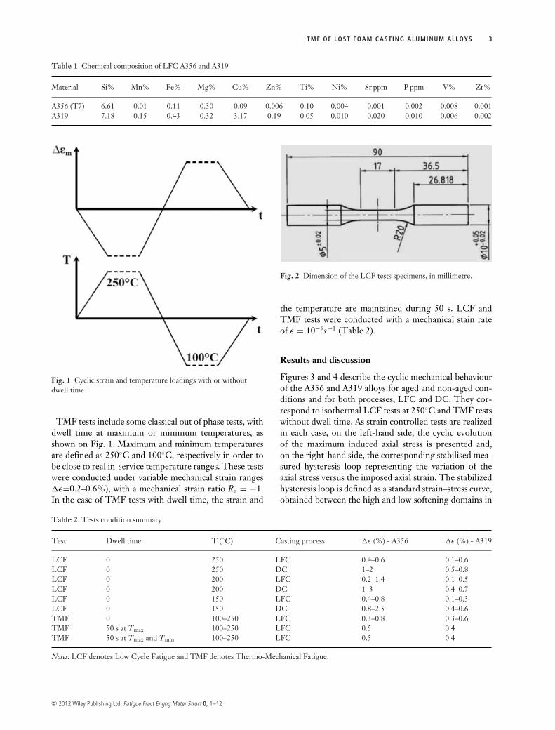
In order to study the cyclic mechanical properties, thefatigue lifetime and the damage mechanisms of LFC ma-terials, strain controlled Low Cycle Fatigue (LCF) andThermo Mechanical Fatigue (TMF)2,3 tests have beenperformed. All samples were extracted from the inter-valve zones which are considered as critical zones for TMFin the fire deck. The dimensions of the specimen are givenof Fig. 2.
c© 2012 Wiley Publishing Ltd. Fatigue Fract Engng Mater Struct 0, 1–12
TMF OF LOST FOAM CASTING ALUMINUM ALLOYS 3
Table 1 Chemical composition of LFC A356 and A319
Material Si% Mn% Fe% Mg% Cu% Zn% Ti% Ni% Sr ppm P ppm V% Zr%
A356 (T7) 6.61 0.01 0.11 0.30 0.09 0.006 0.10 0.004 0.001 0.002 0.008 0.001A319 7.18 0.15 0.43 0.32 3.17 0.19 0.05 0.010 0.020 0.010 0.006 0.002
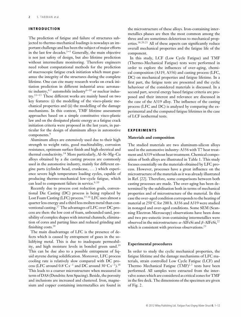
Fig. 1 Cyclic strain and temperature loadings with or withoutdwell time.
TMF tests include some classical out of phase tests, withdwell time at maximum or minimum temperatures, asshown on Fig. 1. Maximum and minimum temperaturesare defined as 250◦C and 100◦C, respectively in order tobe close to real in-service temperature ranges. These testswere conducted under variable mechanical strain ranges�ε=0.2–0.6%), with a mechanical strain ratio Rε = −1.In the case of TMF tests with dwell time, the strain and
Fig. 2 Dimension of the LCF tests specimens, in millimetre.
the temperature are maintained during 50 s. LCF andTMF tests were conducted with a mechanical stain rateof ε = 10−3s −1 (Table 2).
Results and discussion
Figures 3 and 4 describe the cyclic mechanical behaviourof the A356 and A319 alloys for aged and non-aged con-ditions and for both processes, LFC and DC. They cor-respond to isothermal LCF tests at 250◦C and TMF testswithout dwell time. As strain controlled tests are realizedin each case, on the left-hand side, the cyclic evolutionof the maximum induced axial stress is presented and,on the right-hand side, the corresponding stabilised mea-sured hysteresis loop representing the variation of theaxial stress versus the imposed axial strain. The stabilizedhysteresis loop is defined as a standard strain–stress curve,obtained between the high and low softening domains in
Table 2 Tests condition summary
Test Dwell time T (◦C) Casting process �ε (%) - A356 �ε (%) - A319
LCF 0 250 LFC 0.4–0.6 0.1–0.6LCF 0 250 DC 1–2 0.5–0.8LCF 0 200 LFC 0.2–1.4 0.1–0.5LCF 0 200 DC 1–3 0.4–0.7LCF 0 150 LFC 0.4–0.8 0.1–0.3LCF 0 150 DC 0.8–2.5 0.4–0.6TMF 0 100–250 LFC 0.3–0.8 0.3–0.6TMF 50 s at Tmax 100–250 LFC 0.5 0.4TMF 50 s at Tmax and Tmin 100–250 LFC 0.5 0.4
Notes: LCF denotes Low Cycle Fatigue and TMF denotes Thermo-Mechanical Fatigue.
c© 2012 Wiley Publishing Ltd. Fatigue Fract Engng Mater Struct 0, 1–12

4 S . TAB IB IAN et al.
Fig. 3 LCF tests at 250◦C (a) Axial stress cyclic evolution versus number of cycles: aged and non-aged LFC-A319; (b) Stabilized hysteresisloop: aged and non-aged LFC-A319; (c) Axial stress cyclic evolution versus number of cycles: aged and non-aged LFC-A356; (d) Stabilizedhysteresis loop: aged and non-aged LFC-A356.
the cyclic material behaviour, where the maximal stressover the cycle is almost constant. In both cases, the axialstresses are normalized by the maximum stress value ob-tained in the first cycle. However, in the next paragraphs,the ‘normalized maximum stress’ will be simply denotedby the ‘maximum stress’. On these figures, fatigue lifetimeis defined by a 10% drop of maximum stress, before thefracture of specimen.
Influence of aging conditions
Figures 3 and 4 illustrate the influences of aging on LFCalloys for both LCF–TMF tests. Figures on the left-handside represent the evolution of the maximum inducedstress versus the number of applied cycles. The resultsshow that the non-aged A356 has a sudden reduction ofmaximum stress in the few first hundred cycles and then
c© 2012 Wiley Publishing Ltd. Fatigue Fract Engng Mater Struct 0, 1–12
TMF OF LOST FOAM CASTING ALUMINUM ALLOYS 5
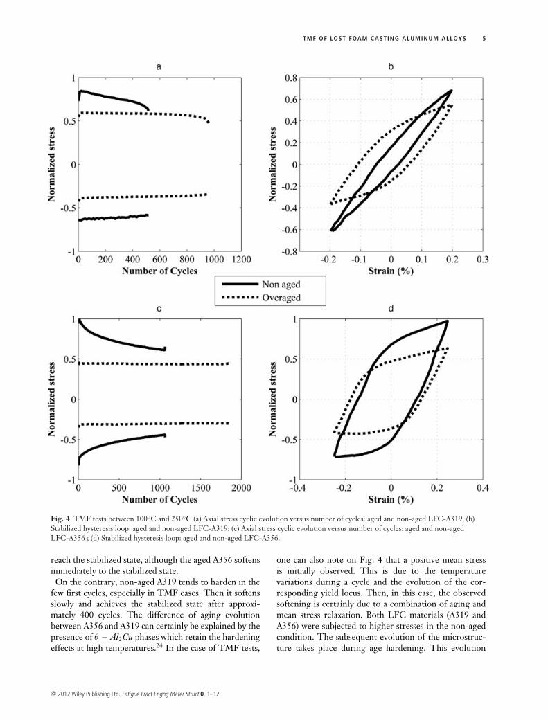
Fig. 4 TMF tests between 100◦C and 250◦C (a) Axial stress cyclic evolution versus number of cycles: aged and non-aged LFC-A319; (b)Stabilized hysteresis loop: aged and non-aged LFC-A319; (c) Axial stress cyclic evolution versus number of cycles: aged and non-agedLFC-A356 ; (d) Stabilized hysteresis loop: aged and non-aged LFC-A356.
reach the stabilized state, although the aged A356 softensimmediately to the stabilized state.
On the contrary, non-aged A319 tends to harden in thefew first cycles, especially in TMF cases. Then it softensslowly and achieves the stabilized state after approxi-mately 400 cycles. The difference of aging evolutionbetween A356 and A319 can certainly be explained by thepresence of θ − Al2Cu phases which retain the hardeningeffects at high temperatures.24 In the case of TMF tests,
one can also note on Fig. 4 that a positive mean stressis initially observed. This is due to the temperaturevariations during a cycle and the evolution of the cor-responding yield locus. Then, in this case, the observedsoftening is certainly due to a combination of aging andmean stress relaxation. Both LFC materials (A319 andA356) were subjected to higher stresses in the non-agedcondition. The subsequent evolution of the microstruc-ture takes place during age hardening. This evolution
c© 2012 Wiley Publishing Ltd. Fatigue Fract Engng Mater Struct 0, 1–12
6 S . TAB IB IAN et al.
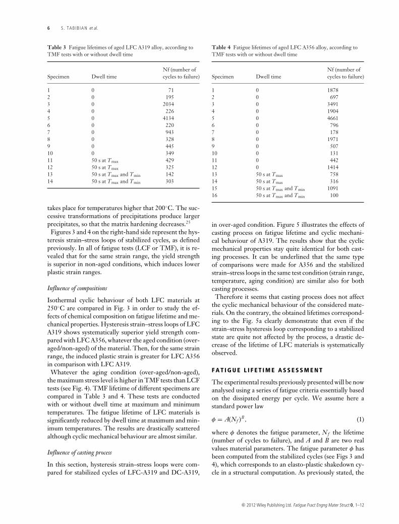
Table 3 Fatigue lifetimes of aged LFC A319 alloy, according toTMF tests with or without dwell time
Nf (number ofSpecimen Dwell time cycles to failure)
1 0 712 0 1953 0 20344 0 2265 0 41346 0 2207 0 9438 0 3289 0 44510 0 34911 50 s at Tmax 42912 50 s at Tmax 32513 50 s at Tmax and Tmin 14214 50 s at Tmax and Tmin 303
takes place for temperatures higher that 200◦C. The suc-cessive transformations of precipitations produce largerprecipitates, so that the matrix hardening decreases.25
Figures 3 and 4 on the right-hand side represent the hys-teresis strain–stress loops of stabilized cycles, as definedpreviously. In all of fatigue tests (LCF or TMF), it is re-vealed that for the same strain range, the yield strengthis superior in non-aged conditions, which induces lowerplastic strain ranges.
Influence of compositions
Isothermal cyclic behaviour of both LFC materials at250◦C are compared in Fig. 3 in order to study the ef-fects of chemical composition on fatigue lifetime and me-chanical properties. Hysteresis strain–stress loops of LFCA319 shows systematically superior yield strength com-pared with LFC A356, whatever the aged condition (over-aged/non-aged) of the material. Then, for the same strainrange, the induced plastic strain is greater for LFC A356in comparison with LFC A319.
Whatever the aging condition (over-aged/non-aged),the maximum stress level is higher in TMF tests than LCFtests (see Fig. 4). TMF lifetime of different specimens arecompared in Table 3 and 4. These tests are conductedwith or without dwell time at maximum and minimumtemperatures. The fatigue lifetime of LFC materials issignificantly reduced by dwell time at maximum and min-imum temperatures. The results are drastically scatteredalthough cyclic mechanical behaviour are almost similar.
Influence of casting process
In this section, hysteresis strain–stress loops were com-pared for stabilized cycles of LFC-A319 and DC-A319,
Table 4 Fatigue lifetimes of aged LFC A356 alloy, according toTMF tests with or without dwell time
Nf (number ofSpecimen Dwell time cycles to failure)
1 0 18782 0 6973 0 34914 0 19045 0 46616 0 7967 0 1788 0 19719 0 50710 0 13111 0 44212 0 141413 50 s at Tmax 75814 50 s at Tmax 31615 50 s at Tmax and Tmin 109116 50 s at Tmax and Tmin 100
in over-aged condition. Figure 5 illustrates the effects ofcasting process on fatigue lifetime and cyclic mechani-cal behaviour of A319. The results show that the cyclicmechanical properties stay quite identical for both cast-ing processes. It can be underlined that the same typeof comparisons were made for A356 and the stabilizedstrain–stress loops in the same test condition (strain range,temperature, aging condition) are similar also for bothcasting processes.
Therefore it seems that casting process does not affectthe cyclic mechanical behaviour of the considered mate-rials. On the contrary, the obtained lifetimes correspond-ing to the Fig. 5a clearly demonstrate that even if thestrain–stress hysteresis loop corresponding to a stabilizedstate are quite not affected by the process, a drastic de-crease of the lifetime of LFC materials is systematicallyobserved.
F A T I G U E L I F E T I M E A S S E S S M E N T
The experimental results previously presented will be nowanalysed using a series of fatigue criteria essentially basedon the dissipated energy per cycle. We assume here astandard power law
φ = A(Nf )B, (1)
where φ denotes the fatigue parameter, Nf the lifetime(number of cycles to failure), and A and B are two realvalues material parameters. The fatigue parameter φ hasbeen computed from the stabilized cycles (see Figs 3 and4), which corresponds to an elasto-plastic shakedown cy-cle in a structural computation. As previously stated, the
c© 2012 Wiley Publishing Ltd. Fatigue Fract Engng Mater Struct 0, 1–12
TMF OF LOST FOAM CASTING ALUMINUM ALLOYS 7
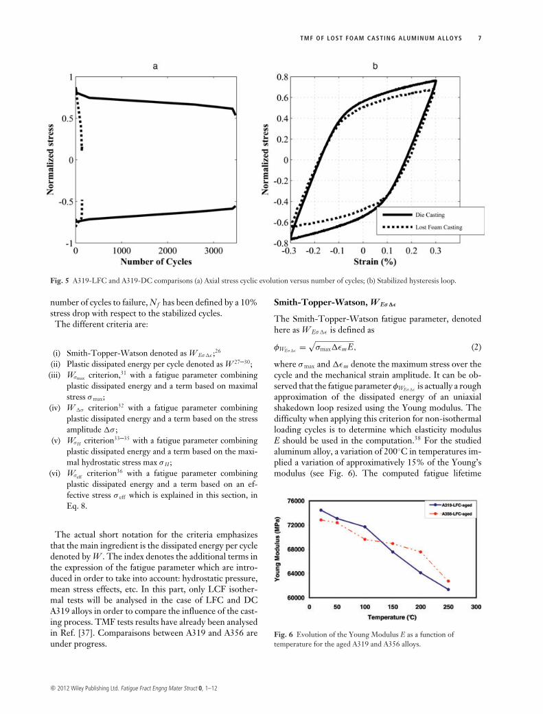
Fig. 5 A319-LFC and A319-DC comparisons (a) Axial stress cyclic evolution versus number of cycles; (b) Stabilized hysteresis loop.
number of cycles to failure, Nf has been defined by a 10%stress drop with respect to the stabilized cycles.
The different criteria are:
(i) Smith-Topper-Watson denoted as W Eσ�ε ;26
(ii) Plastic dissipated energy per cycle denoted as W 27–30;(iii) Wσmax criterion,31 with a fatigue parameter combining
plastic dissipated energy and a term based on maximalstress σ max;
(iv) W �σ criterion32 with a fatigue parameter combiningplastic dissipated energy and a term based on the stressamplitude �σ ;
(v) WσH criterion33–35 with a fatigue parameter combiningplastic dissipated energy and a term based on the maxi-mal hydrostatic stress max σ H ;
(vi) Wσeff criterion36 with a fatigue parameter combiningplastic dissipated energy and a term based on an ef-fective stress σ eff which is explained in this section, inEq. 8.
The actual short notation for the criteria emphasizesthat the main ingredient is the dissipated energy per cycledenoted by W . The index denotes the additional terms inthe expression of the fatigue parameter which are intro-duced in order to take into account: hydrostatic pressure,mean stress effects, etc. In this part, only LCF isother-mal tests will be analysed in the case of LFC and DCA319 alloys in order to compare the influence of the cast-ing process. TMF tests results have already been analysedin Ref. [37]. Comparaisons between A319 and A356 areunder progress.
Smith-Topper-Watson, W Eσ�ε
The Smith-Topper-Watson fatigue parameter, denotedhere as W Eσ�ε is defined as
φWEσ�ε=
√σmax�εm E, (2)
where σ max and �εm denote the maximum stress over thecycle and the mechanical strain amplitude. It can be ob-served that the fatigue parameter φWEσ�ε
is actually a roughapproximation of the dissipated energy of an uniaxialshakedown loop resized using the Young modulus. Thedifficulty when applying this criterion for non-isothermalloading cycles is to determine which elasticity modulusE should be used in the computation.38 For the studiedaluminum alloy, a variation of 200◦C in temperatures im-plied a variation of approximatively 15% of the Young’smodulus (see Fig. 6). The computed fatigue lifetime
Fig. 6 Evolution of the Young Modulus E as a function oftemperature for the aged A319 and A356 alloys.
c© 2012 Wiley Publishing Ltd. Fatigue Fract Engng Mater Struct 0, 1–12
8 S . TAB IB IAN et al.
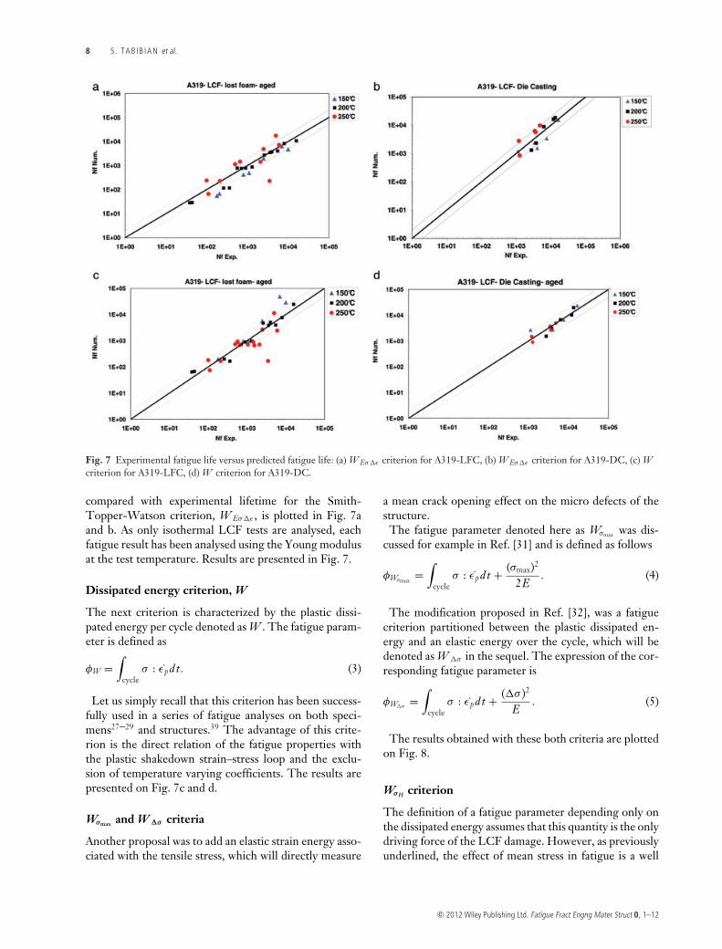
Fig. 7 Experimental fatigue life versus predicted fatigue life: (a) W Eσ�ε criterion for A319-LFC, (b) W Eσ�ε criterion for A319-DC, (c) Wcriterion for A319-LFC, (d) W criterion for A319-DC.
compared with experimental lifetime for the Smith-Topper-Watson criterion, W Eσ�ε , is plotted in Fig. 7aand b. As only isothermal LCF tests are analysed, eachfatigue result has been analysed using the Young modulusat the test temperature. Results are presented in Fig. 7.
Dissipated energy criterion, W
The next criterion is characterized by the plastic dissi-pated energy per cycle denoted as W . The fatigue param-eter is defined as
φW =∫
cycleσ : εp d t. (3)
Let us simply recall that this criterion has been success-fully used in a series of fatigue analyses on both speci-mens27–29 and structures.39 The advantage of this crite-rion is the direct relation of the fatigue properties withthe plastic shakedown strain–stress loop and the exclu-sion of temperature varying coefficients. The results arepresented on Fig. 7c and d.
Wσmax and W �σ criteria
Another proposal was to add an elastic strain energy asso-ciated with the tensile stress, which will directly measure
a mean crack opening effect on the micro defects of thestructure.
The fatigue parameter denoted here as Wσmax was dis-cussed for example in Ref. [31] and is defined as follows
φWσmax=
∫cycle
σ : εp d t + (σmax)2
2E. (4)
The modification proposed in Ref. [32], was a fatiguecriterion partitioned between the plastic dissipated en-ergy and an elastic energy over the cycle, which will bedenoted as W �σ in the sequel. The expression of the cor-responding fatigue parameter is
φW�σ=
∫cycle
σ : εp d t + (�σ )2
E. (5)
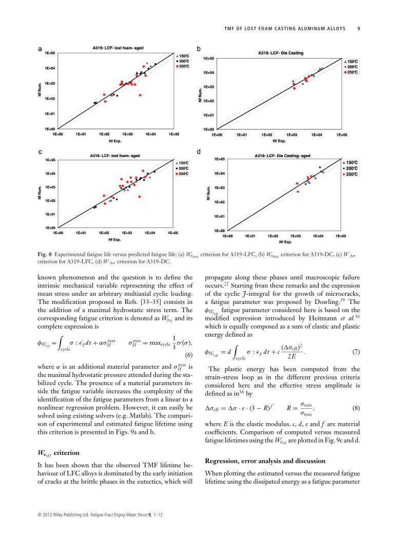
The results obtained with these both criteria are plottedon Fig. 8.
WσH criterion
The definition of a fatigue parameter depending only onthe dissipated energy assumes that this quantity is the onlydriving force of the LCF damage. However, as previouslyunderlined, the effect of mean stress in fatigue is a well
c© 2012 Wiley Publishing Ltd. Fatigue Fract Engng Mater Struct 0, 1–12
TMF OF LOST FOAM CASTING ALUMINUM ALLOYS 9
Fig. 8 Experimental fatigue life versus predicted fatigue life: (a) Wσmax criterion for A319-LFC, (b) Wσmax criterion for A319-DC, (c) W �σ
criterion for A319-LFC, (d) W �σ criterion for A319-DC.
known phenomenon and the question is to define theintrinsic mechanical variable representing the effect ofmean stress under an arbitrary multiaxial cyclic loading.The modification proposed in Refs. [33–35] consists inthe addition of a maximal hydrostatic stress term. Thecorresponding fatigue criterion is denoted as WσH and itscomplete expression is
φWσH=
∫cycle
σ : εp d t + ασ maxH σ max
H = maxcycle13
tr(σ ),
(6)
where α is an additional material parameter and σ maxH is
the maximal hydrostatic pressure attended during the sta-bilized cycle. The presence of a material parameters in-side the fatigue variable increases the complexity of theidentification of the fatigue parameters from a linear to anonlinear regression problem. However, it can easily besolved using existing solvers (e.g. Matlab). The compari-son of experimental and estimated fatigue lifetime usingthis criterion is presented in Figs. 9a and b.
Wσe f f criterion
It has been shown that the observed TMF lifetime be-haviour of LFC alloys is dominated by the early initiationof cracks at the brittle phases in the eutectics, which will
propagate along these phases until macroscopic failureoccurs.22 Starting from these remarks and the expressionof the cyclic J-integral for the growth of microcracks,a fatigue parameter was proposed by Dowling.29 TheφWσeff
fatigue parameter considered here is based on themodified expression introduced by Heitmann et al.36
which is equally composed as a sum of elastic and plasticenergy defined as
φWσeff= d
∫cycle
σ : εp d t + c(�σeff )2
2E. (7)
The plastic energy has been computed from thestrain–stress loop as in the different previous criteriaconsidered here and the effective stress amplitude isdefined as in36 by
�σeff = �σ · e · (3 − R) f R = σmin
σmax, (8)
where E is the elastic modulus. c, d, e and f are materialcoefficients. Comparison of computed versus measuredfatigue lifetimes using the Wσeff are plotted in Fig. 9c and d.
Regression, error analysis and discussion
When plotting the estimated versus the measured fatiguelifetime using the dissipated energy as a fatigue parameter
c© 2012 Wiley Publishing Ltd. Fatigue Fract Engng Mater Struct 0, 1–12
10 S . TAB IB IAN et al.
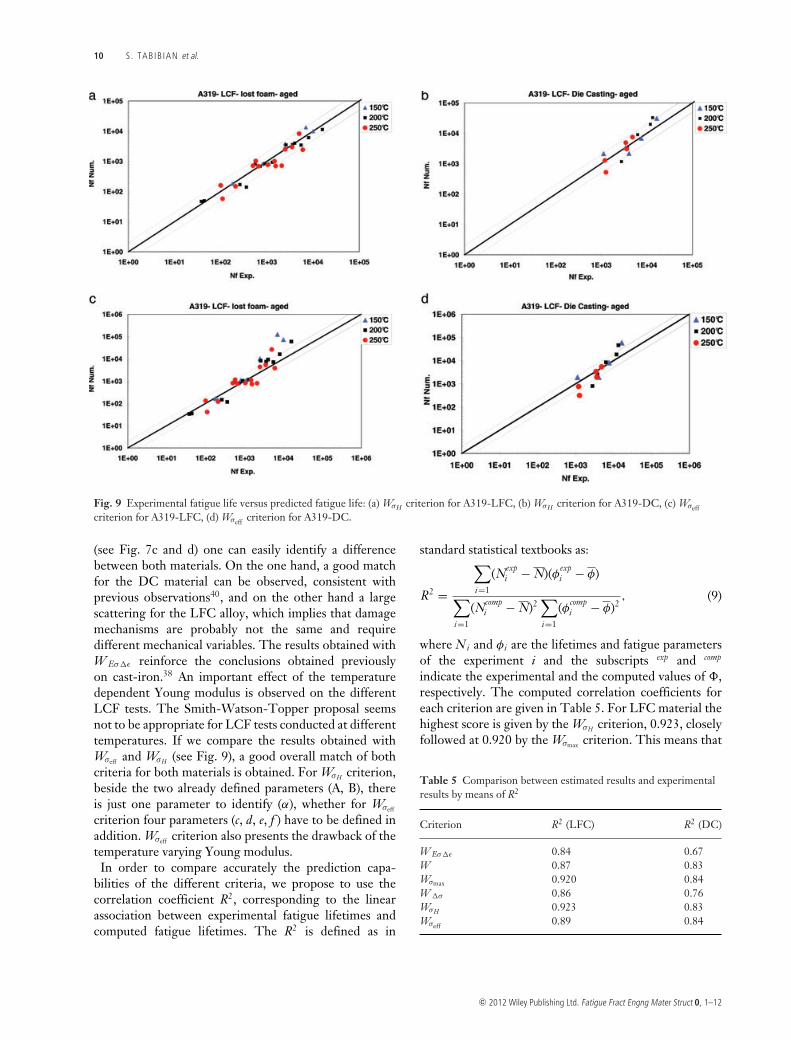
Fig. 9 Experimental fatigue life versus predicted fatigue life: (a) WσH criterion for A319-LFC, (b) WσH criterion for A319-DC, (c) Wσeffcriterion for A319-LFC, (d) Wσeff criterion for A319-DC.
(see Fig. 7c and d) one can easily identify a differencebetween both materials. On the one hand, a good matchfor the DC material can be observed, consistent withprevious observations40, and on the other hand a largescattering for the LFC alloy, which implies that damagemechanisms are probably not the same and requiredifferent mechanical variables. The results obtained withW Eσ�ε reinforce the conclusions obtained previouslyon cast-iron.38 An important effect of the temperaturedependent Young modulus is observed on the differentLCF tests. The Smith-Watson-Topper proposal seemsnot to be appropriate for LCF tests conducted at differenttemperatures. If we compare the results obtained withWσeff and WσH (see Fig. 9), a good overall match of bothcriteria for both materials is obtained. For WσH criterion,beside the two already defined parameters (A, B), thereis just one parameter to identify (α), whether for Wσeff
criterion four parameters (c, d, e, f ) have to be defined inaddition. Wσeff criterion also presents the drawback of thetemperature varying Young modulus.
In order to compare accurately the prediction capa-bilities of the different criteria, we propose to use thecorrelation coefficient R2, corresponding to the linearassociation between experimental fatigue lifetimes andcomputed fatigue lifetimes. The R2 is defined as in
standard statistical textbooks as:
R2 =
∑i=1
(Nexpi − N)(φexp
i − φ)
∑i=1
(Ncompi − N)2
∑i=1
(φcompi − φ)2
, (9)
where Ni and φi are the lifetimes and fatigue parametersof the experiment i and the subscripts exp and comp
indicate the experimental and the computed values of ,respectively. The computed correlation coefficients foreach criterion are given in Table 5. For LFC material thehighest score is given by the WσH criterion, 0.923, closelyfollowed at 0.920 by the Wσmax criterion. This means that
Table 5 Comparison between estimated results and experimentalresults by means of R2
Criterion R2 (LFC) R2 (DC)
W Eσ�ε 0.84 0.67W 0.87 0.83Wσmax 0.920 0.84W �σ 0.86 0.76WσH 0.923 0.83Wσeff 0.89 0.84
c© 2012 Wiley Publishing Ltd. Fatigue Fract Engng Mater Struct 0, 1–12
TMF OF LOST FOAM CASTING ALUMINUM ALLOYS 11
the expressions of both criteria capture the macroscopiceffect of the microstructure on the fatigue life. Whencompared to other representations of the mean stress, onecan state that the main interest of the WσH criterion con-sists in its multiaxial formulation. Therefore this damagevariable is easy to implement as a post-processing to FEstructural computations as it is intrinsic and not based onsome operator dependent interpretation of the loadingpath. Moreover, the obtained results are consistent withrecent results obtained on TMF non-isothermal tests, asshown previously by the authors.37
C O N C L U S I O N
The purpose of this paper was to study the cyclic mechan-ical properties and the fatigue lifetime of A356 and A319alloys used in cylinder heads manufactured by a LFC pro-cess. Since a few years, this process has been extensivelyused in the automotive industry and the induced fatigueproperties are crucial in order to improve the durabilityand reliability of components. LCF–TMF test results re-vealed different cyclic mechanical and fatigue propertiesdepending on the alloy and on the manufacturing process.Among others, one can note a higher yield stress for theA319 alloy compared with A356 and shorter lifetimes forLFC process compared with DC process for equivalentloading conditions.
In the case of A319 alloy obtained by LFC and DCprocesses, different thermo-mechanical energy-based fa-tigue criteria were used to estimate the fatigue lifetimes inisothermal LCF at different temperatures. It was shownthat WσH and Wσmax criteria present a good agreement be-tween experimental and computed results. Incorporatingmaximum stress or hydrostatic pressure in an energeticapproach seems to be a consistent proposal in order to takeinto account macroscopically the microstructural damagemechanisms in such aluminum alloys. Moreover, the prin-cipal interest of the WσH criterion consists in its multiaxialformulation which is consistent with a post-analysis of FEstructural computations under arbitrary loadings. Thisconclusion is consistent with recent results obtained onTMF non-isothermal tests, as shown previously by theauthors37
A c k n o w l e d g e m e n t s
The authors would like to thank David Balloy, Jean-YvesDauphin and Jean-Charles Tissier at the Ecole Centralede Lille, France, for their help in SEM analysis and fruit-ful discussion during this work. We wish to acknowledgeAlexandra Marie-Louise at PSA Peugeot-Citroen for pro-viding a vast experimental database.
This work was supported by PSA Peugeot-Citroen andhas received the financial support of the French Ministerof Science, which are both gratefully acknowledged.
R E F E R E N C E S
1 Sehitoglu, H. (1996) Thermal and thermomechanical fatigueof structural alloys. ASM Handbook 19, 527–556.
2 Remy, L. (2003) Thermal-mechanical fatigue (includingthermal shock). In: Comprehensive Structural Integrity (Editedby I. Milne, R.O. Ritchie and B. Karihaloo), Elsevier, Vol. 5,pp. 113–200. http://dx.doi.org/10.1016/B0-08-043749-4/05021-7
3 Charkaluk, E. and Remy, L. (2010) Thermal fatigue. In:Fatigue of Materials and Structures: Application to Damage andDesign, Vol. 2. London: Wiley ISTE.ISBN-978-1-84821-267-1.
4 Chaboche, J. L. and Stoltz, C. (1974) Determination desdurees de vie des aubes de turbines a gaz. Revue Francaise deMecanique 52, 37–47.
5 Chaboche, J. L. and Gallerneau, F. (2001) An overview of thedamage approach to durability modeling at elevatedtemperature. Fatigue Fract. Eng. Mater. Struct. 24, 405–417.
6 Nagayoshi, T. and Kodaira, T. (1993) Analysis of thermalfatigue cracks in cylinder heads. JSAE Rev. 14, 56–60.
7 Sehitoglu, H., Foglesong, T. and Maier, H. J. (2005)Precipitate effects on the mechanical behavior of aluminumcopper alloys part i: Experiments. Metal. Mater. Trans. 36A,749–761.
8 Smith, T., Maier, H., Sehitoglu, H., Fleury, E. and Allison, J.(1999) Modelling high-temperature stress-strain behavior ofcast aluminum alloys. Metal. Mater. Trans. 30A, 133–146.
9 Thomas, J. J., Verger, L., Bignonnet, A. and Charkaluk, E.(2004) Thermomechanical design in the automotive industry.Fatigue Fract. Eng. Mater. Struct. 27, 887–895.
10 Fischersworring-Bunk, A., Thalmair, S., Eibl, M., Kunst, M.and Dietsche, A. (2007) High temperature fatigue and creepautomotive power train application perpectives. JMST 23,1389–1395.
11 Lemaitre, J. and Plumtree, A. (1979) Application of damageconcepts to predict creep-fatigue failures. J. Eng. Mater. Tech.101, 284–292.
12 Sermage, J. P., Lemaitre, J. and Desmorat, R. (2000)Multiaxial creep-fatigue under anisothermal conditions.Fatigue Fract. Eng. Mater. Struct 23, 241–252.
13 Fissolo, A., Gourdin, C., Ancelet, O., Amiable, S.,Demassieux, A., Chapuliot, S., Haddar, N., Mermaz, F.,Stelmaszyk, J. M., Constantinescu, A., Vincent, L. andMaillot, V. (2009) Crack initiation under thermal fatigue: anoverview of cea experience: Part ii (of ii): application of variouscriteria to biaxial thermal fatigue tests and a first proposal toimprove the estimation of the thermal fatigue damage. Int. J.Fatigue 31, 1196–1210.
14 Gruzleski, J. E. and Closset, B. M. (1990). The Treatment ofLiquid Aluminum-Silicon Alloys. American Foundrymen’sSociety Inc., Des Plaines, Illinois, pp. 1–18.
15 Monroe, R. W. (1992) Expendable Pattern Casting. AmericanFoundrymen’s Society Inc., Des Plaines, Illinois, pp. 1–10.
16 Heine, H. J. (1986) Evaporation pattern casting developments.Foundry M&T , p. 36, October.
c© 2012 Wiley Publishing Ltd. Fatigue Fract Engng Mater Struct 0, 1–12
12 S . TAB IB IAN et al.
17 Shivkumar, S., Wang, L. and Apelian, D. (1990) The lost-foamcasting of aluminium alloy components. JOM 42(2), 38–42.
18 Rob Albonetti. (2000) Porosity and intermetallic formation inlost foam casting of A356 alloy. Master’s thesis, TheUniversity of Western Ontario, February 2000.
19 Davis, J. R. (1993) ASM specialty handbook: aluminium andaluminium alloys. ASM Int. 719, 98–100.
20 Ammar, H. R., Samuel, A. M. and Samuel, F. H. (2008)Porosity and the fatigue behavior of hypoeutectic andhypereutectic aluminum-silicon casting alloys. Int. J. Fat. 30,1024–1035.
21 Ran, G., Zhou, J. E. and Wang, Q. G. (2008) Precipitates andtensile fracture mechanism in a sand cast A356 aluminumalloy. J. Mater. Proc. Tech. 207, 46–52.
22 Tabibian, S., Charkaluk, E., Constantinescu, A., Oudin, A.and Szmytka, F. (2010) Behavior, damage and fatigue lifeassessment of lost foam casting aluminum alloys underthermo-mechanical conditions. Proc. Eng. 2, 1145–1154.
23 Backerud, L., Chai, G. and Tamminen, J. (1990) Solidificationcharacteristics of aluminum alloys. In Foundry alloys.Stockholm, Sweden: AFS/SkanAluminum.
24 Guillot, I., Barlas, B., Cailletaud, G., Clavel, M. andMassinon, D. (2002) Thermomechanical fatigue and aging ofcast aluminium alloy: a link between numerical modelling andmicrostructural approach. Eur. Struct. Integr. Soc. 29, 75–84.
25 Eric Nicouleau-Bourles. (1999) Etude experimentale etnumerique du vieillissement d’un alliage d’aluminium.Application aux culasses automobiles (In French). PhD thesis,Ecole Nationale Superieure des Mines de Paris.
26 Smith, K. N., Watson, P. and Topper, T. H. (1970) Astress-strain function for the fatigue of metals. JOM, 5,767–778.
27 Feltner, C. E. and Morrow, J. D. (1961) Micro-plastic strainhysteresis energy a criterion for fatigue fracture. J. Basic Eng.Trans. A.S.M.E, 83, 15–22.
28 Morrow, J. (1965) Cyclic plastic strain energy and fatigue ofmetals. Int. Frict. Damp. Cyclic Plasticity STP 378, 45–87.
29 Dowling, N. E. (1972) Fatigue failure predictions forcomplicated stress-strain histories. JOM 7, 71–87.
30 Charkaluk, E., Bignonnet, A. and Thomas, J.-J. (2004)Dimensionnement a la fatigue thermomecanique de structuresdans l’industrie automobile. Mecanique et Industries 5,27–40.
31 Koh, S. K. (2002) Fatigue damage evaluation of a highpressure tube steel using cyclic strain energy density. Int. J.Pressure Vessels Piping 79, 791–798.
32 Maurel, V., Remy, L., Dahmen, F. and Haddar, N. (2009) Anengineering model for low cycle fatigue life based on apartition of energy and micro-crack growth. Int. J. Fatigue 31,952–961.
33 Amiable, S., Chapuliot, S., Constantinescu, A. and Fissolo, A.(2005) A comparison of lifetime prediction methods for athermal fatigue experiment. Int. J. Fatigue 28, 692–706.
34 Amiable, S., Chapuliot, S., Constantinescu, A. and Fissolo, A.(2006) A computational lifetime prediction for a thermal shockexperiment, Part I : thermomechanical modeling and lifetimeprediction. Fatigue Fract. Eng. Mater. Struct. 29, 209–217.
35 Amiable, S., Chapuliot, S., Constantinescu, A. and Fissolo, A.(2006) A computational lifetime prediction for a thermalshock experiment, Part II : discussion on different fatiguecriteria. Fatigue Fract. Eng. Mater. Struct. 29, 219–227.
36 Heitmann, H. H., Vehoff, H. and Neumann, P. (1984) LifePrediction for Random Load Fatigue based on the GrowthBehaviour of Microcracks. 6th Int. Conf. Fracture, New Delhi,edited by S.R. Valluri et al., Pergamon Press Ltd, Oxford,vol. 4, pp. 3599–3606.
37 Tabibian, S., Charkaluk, E., Constantinescu, A., Szmytka, F.and Oudin, A. (2012) TMF-LCF life assessment of a LostFoam Casting A319 aluminum alloy. Int. J. Fatigue, in press.
38 Charkaluk, E. and Constantinescu, A. (2000) An energeticapproach in thermomechanical fatigue for siliconmolybdenum cast iron. Mater. High Temperatures 3, 373–380.
39 Constantinescu, A., Charkaluk, E., Lederer, G. and Verger, L.(2004) A computational approach to thermomechanicalfatigue. Int. J. Fatigue 26, 805–818.
40 Verger, L. (2002) Sur la fatigue thermomecanique d’un alliaged’aluminium (In French). PhD thesis, Ecole polytechnique.
c© 2012 Wiley Publishing Ltd. Fatigue Fract Engng Mater Struct 0, 1–12