Embed Size (px)
Citation preview

Page 1 of 35
Caution:Please read this Manual thoroughly.If you do not understand or are unsure of anyinformation contained in this Manual pleasecontact your Agent or BIOQUELL forclarification.
OPERATING MANUAL
ASTECEDU 96 MOBILE FUME CUPBOARD
(TM160-O&M-001- Revision 3)
part of BIOQUELL (UK) Limited© BIOQUELL UK LTD
52 Royce CloseWest Portway, AndoverHampshire, SP10 3TS
United KingdomTel: 01264 835835
Fax: 01264 835836Email: [email protected]
Revision 3 http://www.bioquell.com


Page 3 of 35
1 INTRODUCTION
The Astec EDU 96 Mobile Fume Cupboard (Fig. 1), is a recirculatory typeunit that has been designed for use in school laboratories.
The Astec EDU 96 Mobile Fume Cupboard, when fitted with a Filtrete pre-filter, an EDU carbon filter and operated with the front glazing fully down,conforms to the requirements of DFE Design Note 29 and Buildings Bulletin88, Fume Cupboards in Schools. This product has been tested andapproved by CLEAPSS. It will satisfactorily absorb the substances releasedin normal educational science activities, up to A-Level, namely those listed inSection 10.
Figure 1 Astec EDU 96 Mobile Fume Cupboard
THE FUME CUPBOARD FITTED WITH THE FILTERS DESCRIBEDABOVE WILL NOT ABSORB HYDROGEN, CARBON MONOXIDE,METHANE OR THE NITROUS OXIDE.
Filters have a high efficiency but, because the nose is very sensitive, theresidual gases passing through the filter may sometimes be smelt, eventhough their level is not hazardous. However, should they cause distress,the operation should be finished and the filter saturation monitored.

Page 4 of 35
Users releasing hazardous vapours or gases not normally used in scienceeducation up to A-Level or unusually large quantities of substances normallyused in school science up to A-Level, must make their own assessment asto whether it is safe to do so.
Similarly, if this fume cupboard is fitted with a filter different from that namedabove, users must make their own assessment as to its efficiency.
The EDU has the following specification:
Size (W x D x H): 980 x 700 x 1790mm
Weight: 160kg
Power: 600w
Current Drawing: 2.6Amps
Noise : <50dB (A)

Page 5 of 35
2 INSTALLATION
WARNING:INSTALLATION SHOULD ONLY BE CARRIED OUT BY TRAINED ANDAPPROVED ENGINEERS OR AGENTS.
ASTEC MICROFLOW OR ITS AGENTS CANNOT ACCEPTRESPONSIBILITY FOR DAMAGE, LOSS OR INJURY CAUSED BY, ORRESULTING FROM, INCORRECTLY INSTALLED EQUIPMENT.
The units are supplied ready assembled and complete with a mains plug.They only require assembly of the filters.
The plug is fused with a 5 Amp fuse.
2.1 SERVICES (IF FITTED)
Refer to Fig. 2.
2.1.1 Drains
The cabinet is supplied with a 1.5” Vulcathene hose to the bottle trap. Theother end is connected to a drain inlet position on the wall. There is anadapter supplied with the hose and drain outlet can be 1.5” BSP FEMALE or1.5” VULCATHENE FEMALE.
The drain outlet should be supplied with a cap for use when the cabinet isdisconnected. The drain inlet position should be as low as practical to allowfall from cabinet drip cup to drain. As an alternative the hose may beconnected to a container or surface drain. Care is required to empty thehose prior to disconnection.
2.1.2 Water
The tap is connected to a blue hose terminating in a quick release fitting.The body of the quick release fitting is connected to a 0.25” BSP MALEOUTLET point on the wall.
2.1.3 Gas
A Gas Board approved tap and stainless steel reinforced metal hose andquick release fitting are provided for connection to a 0.125” BSP MALEOUTLET point on the wall. The installation must be checked by an approvedengineer.
Further quick release fittings for multiple point use can be supplied to order.
2.1.4 Electrics
An electric socket is located on the top left-hand side of the unit. Onlyelectrical items requiring 2 Amps or less should be plugged into the unit.

Page 6 of 35
Figure 2 EDU 96 Services - Right Hand Side View
Located on L/H side.Mains electric supply 3 m of cable with 13 Amp plug fitted.
Waste outlet. 1.5 m hose supplied.Maximum height for connection 500 mm.Requires 1.5” BSP female socket or as washing machine waste.
½” BSP male spigot.Customer to connect to their water service.1 supplied with unit, Part Number 203-3509.
¼” BSP male spigot.Customer to connect to their gas supply.1 supplied with unit, Part Number 206-3501.Gas Board approved hose
Quick release coupling
Page 7 of 35
2.2 FITTING OF FILTERS
The filter and pre-filter will be supplied separately and should be fitted inaccordance with Section 3.
2.3 GENERAL INSTALLATION RECOMMENDATIONS
To avoid air currents in the room affecting the performance of fumecupboards, British Standards BS 7258, Part 2 1990, Design Note 29 andBuildings Bulletin 88 make the following recommendations:
Units should be sited so that the airflow into the front aperture is nothindered by walls, other fume cupboards cross draughts etc. In particular,any wall in front of it should be positioned so that the effects of doors andwindows in producing cross draughts are minimised. Ideally, the facevelocity should be measured and the variation checked in all sites likely to beused, under the conditions of ventilation likely to be relevant.
The fume cupboard should never be sited where it blocks an escape route.
2.4 MONITORING
The unit will require regular monitoring for airflow and filter condition. Thisshould be carried out every fourteen months in order to comply with COSHHRegulations. The monitoring procedure is described in Section 6.
Page 8 of 35
3 FITTING AND REMOVAL OF FILTERS
For schools use an EDU filter should always be used.
Hazards associated with the removal and disposal of filters will depend onthe use to which the filtration fume cupboard has been put. In a normalschools situation the filter can be removed in the laboratory. Plastic glovesand a strong plastic bag are supplied with each filter. Plastic gloves shouldbe used when handling dirty filters and the filter should be put into the strongplastic bag and sealed prior to disposal. The ideal method of disposal isincineration, but if this is not possible, the filter should be double bagged,well sealed and put in the domestic waste.
The filter access panel is mounted on the front left hand side of the cabinetand is removed using the 180 turn fasteners.
3.1 MAIN CARBON FILTERS
The multi-layer activated carbon filter for schools is supplied separately in aplastic wrapping. The filter has a foam rubber seal on its upper face aroundthe edge and this seal must not be damaged or missing.
To install/change filter:
(a) Open the access door, remove carefully and undo the earth strap.
(b) Pull the clamping handle across the unit from right to left. This willautomatically release the clamping bars.
(c) Slide the filter out and place in a plastic bag ready for disposal.
(d) Insert the new filter in the unit with the foam rubber seal uppermost andslide into position against the back stop.
(e) Re-clamp the filter by moving the handle from left to right into the unit.
(f) Rest the new pre-filter on top of the filter between the clamping frameensuring the carbon filter is covered.
(g) Replace the door and earthing strap.
3.2 PRE-FILTER
The pre-filter is a white electrostatically charged Filtrete which sits on top ofthe main filter. To change the pre-filter, open the filter access door, takingcare to undo the earthing strap, remove the pre-filter. Place the new pre-filter on the main carbon filter and replace door making sure the earthingstrap is reconnected.

Page 9 of 35
4 GENERAL OPERATING INSTRUCTIONS
4.1 The fume cupboard is fitted with a filter for use on schools curriculum. If thecabinet is to be used for any other purpose, please consult Astec Microflow(BIOQUELL UK) for suitability of filter. Many different types of filter areavailable for specific purposes.
4.2 The EDU 96 will start at the normal operating speed at switch on.
4.3 The airflow and filter saturation should be checked on a regular basis.Appendices 3 and 4 gives details.
4.4 A Bunsen burner should not be placed too close to the side or back panels(150 mm). The Bunsen burner or other heat source should be positionedaway from the back baffle screen. Flame height should not exceed 100 mm.Bunsen burners should only be lit when the fan is switched ON.
4.5 The spillage tray is manufactured from glass reinforced plastic and has achemically resistant gel coat though any chemical spillage’s should beremoved from the surface as soon as possible.
4.6 It should be noted the Activated Carbon filter blocks do NOT absorb carbonmonoxide/hydrogen or nitrogen oxides. However, small quantities (such asused in schools) will not present a hazard due to the large dilution effect ofthe airflow through the unit and retardation of the fumes in the filter matrix.
4.7 Astec fume cupboards are designed to handle fumes and vapours given offduring normal laboratory procedures. It is not recommend that largequantities of acid or solvents are boiled off in the fume cupboard.
4.8 Spare pre-filters should always be kept available and preferably a main filter.The activated multi-layer carbon filter used for normal school use will last fora number of years. It is a requirement under COSHH regulations thatventilation equipment is checked every 14 months for safe operation andfurther information is supplied in Appendix 1.
4.9 High concentrations of fumes entering the filter block may temporarily reducethe filtration efficiency. For this reason any major spillage within the fumecupboard should be cleared up immediately, preferably using spillageabsorption granules, rather than tissue paper, which may aggravate theevaporation of toxic fumes from the spillage area.
4.10 Following a major spillage the main filters must be stabilised, as the heat ofwetting may reduce filter efficiency. After stabilisation, the old filters cannormally be re-used, provided saturation has not been reached. A guide isnot to use the cabinet for several hours and then to run the cabinet withoutany chemical fumes for 2-3 hours. Check the exhaust for the presence ofthe spilled chemical with chemical detection tubes.

Page 10 of 35
4.11 The electrical equipment in the cabinet including light fittings and controlequipment are in separate enclosures, which are ventilated with fresh roomair. The equipment should not be used in a flammable room atmosphere.

Page 11 of 35
5 CONTROL PANEL
The features of the Control Panel are shown in Fig. 3.
Figure 3 Control Panel Features
5.1 MAINS ON/OFF
Press the switch down to switch on. A green indicator lamp will indicate thatpower is connected to the unit. The fan will run at full speed, ready fornormal operation of the fume cupboard and the lights, if fitted, will come on.The cupboard can be used immediately.
5.2 HOUR COUNTER
This indicates the total number of hours running time of the fan.
5.3 LOW AIRFLOW ALARM
The alarm is a red light located at the front of the unit. In normal operation,the red light will not come on.
If the red indicator lamp starts to flashes on intermittently or stays on, thepre-filter is starting to block with dust and an airflow reading should be takenat the aperture to determine if the pre-filter requires changing. We advisechanging the pre-filter if an airflow of 0.3 m/sec cannot be maintained.
The correct operation of the alarm may be tested as described in Appendix3, instructions on replacing filters are given in Section 3 of this manual.
5.4 FILTER ALARM/STATUS (IF FITTED)
The green LED is constantly displayed while the filter is actively absorbingthe chemical fumes. The LED goes out every six seconds as themechanism samples the air stream. When a chemical breakthrough isdetected the red LED comes on intermittently and an audible alarm bleeps 4times every minute showing the filter requires changing. See Appendix 4 forcalibration and testing.
5.5 ACID DETECTION SYSTEM (IF FITTED)
A simple optional detector system for inorganic acid gases can be fitted tothe fume cupboard.
LOW AIRFLOW
FILTERALARM
(OPTIONAL) HOUR COUNTER ON/OFF

Page 12 of 35
The green LED will indicate the absence of acid gases, and a red LED willalert the user to acid fumes in the return air to the laboratory, an audiblealarm will also sound.
5.6 TESTING THE ACID DETECTOR ALARM
The alarm can be simply checked by removing the indicator paper from theholder as follows:
(a) Switch on the unit, the green LED should be on.
(b) Open right-hand cupboard door.
(c) Slide the cover off the detector.
(d) Remove the indicator paper. The green LED should go out, the redLED will come on and the alarm sound.
(e) Insert the detector paper, green light should come back on.

Page 13 of 35
6 MONITORING
6.1 GENERAL
Under the “Control of Substances Hazardous to Health” (COSHH)regulations, it is mandatory to check ventilation equipment at “suitableintervals” for correct operation. A suggested maintenance schedule andrecord sheet are given. This section of the manual reviews manual methodsof filter condition and airflow monitoring.
The purpose of monitoring is to detect when the pre-filter or main filterscease to operate effectively. If the pre-filters are blocked, the airflow will bereduced at the fume cupboard aperture. If the main filters are saturated theywill cease to remove the fumes effectively.
The EDU 96 is fitted with a low airflow alarm as previously described.
Airflow measurements should be made occasionally, preferably once a term,to check the face velocity, as described below.
Monitoring for filter saturation should be carried out at least once a year,preferably once a term, as described below.
If an odour is noticed, it is sensible to check the fume cupboard. However, itmust be remembered that the sense of smell is very sensitive for somechemicals (e.g. Ammonia or hydrogen sulphide) and a slight smell does notmean that the exhaust levels of chemicals have approached the maximumacceptable concentration.
6.2 AIRFLOW MEASUREMENTS
An anemometer should be used to check the airflow (face velocity) at theworking aperture. Any suitable anemometer may be used, including hot wireor vane anemometer. A minimum of nine readings should be taken acrossthe working aperture, as shown on the record sheet. Note the results on therecord form. If the airflow drops below 0.3 m/sec it is mandatory to recordthis data.
A low cost vane anemometer is available from Astec Microflow (part numberMOG-002). This will indicate the airflow has not altered greatly from thevalue obtained at the annual test when a calibrated, more accurateanemometer should be used.
Page 14 of 35
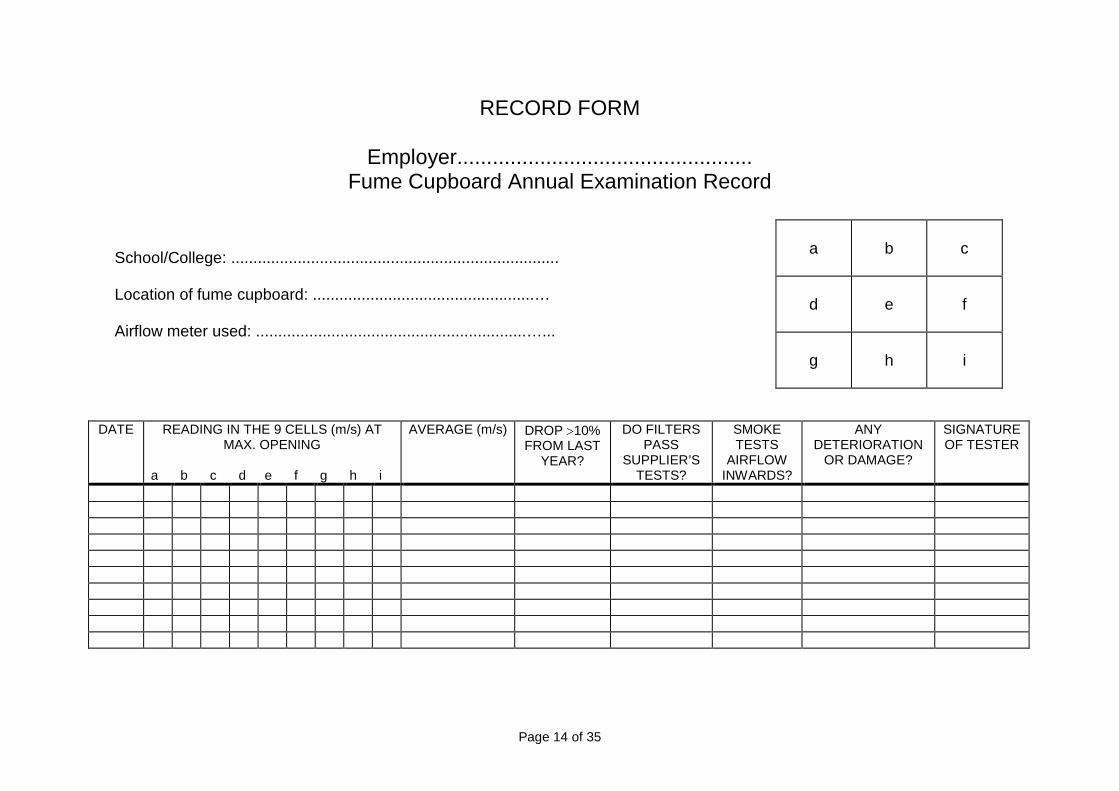
RECORD FORM
Employer..................................................Fume Cupboard Annual Examination Record
School/College: ..........................................................................
Location of fume cupboard: ..................................................…
Airflow meter used: .............................................................…...
DATE READING IN THE 9 CELLS (m/s) ATMAX. OPENING
a b c d e f g h i
AVERAGE (m/s) DROP 10%FROM LAST
YEAR?
DO FILTERSPASS
SUPPLIER’STESTS?
SMOKETESTS
AIRFLOWINWARDS?
ANYDETERIORATION
OR DAMAGE?
SIGNATUREOF TESTER
a b c
d e f
g h i

Page 15 of 35
6.3 FACE VELOCITY MEASUREMENTS
6.3.1 Procedure
(a) Imagine the face of the fume cupboard divided into nine cells. Stand asfar as practicable from the fume cupboard with the anemometersensing head in the plane of the sash and take airflow readings atapproximately the centres of the nine cells.
(b) Record for each cell the approximate average reading over a period ofat least ten seconds, applying any correction from the calibration chart.Air movement fluctuations in the laboratory often make this quitedifficult and it may be necessary to take a reading which averages overa longer period.
(c) Look at the table and repeat any reading which seems to be verydifferent from the general pattern. Record the average of this and theprevious reading.
6.3.2 Calculation
6.3.2.1 Minimum Face Velocity
Record which of a,b,c,d,e,f,g,h,i is the smallest, i.e., record the minimumface velocity.
Is it above or below 0.3 m/s-1 ? If below, the fume cupboard FAILS.
6.3.2.2 Variation
(Useful for checking if sites are suitable)
Add a,b,c,d,e,f,g,h,i and divide by 9 to get the average.
Find the biggest and smallest out of a,b,c,d,e,f,g,h,i.
Work out: biggest minus average. Divide the answer by the average andmultiply by 100 to obtain the upper percentage variation.
Work out: average minus smallest. Divide the answer by the average andmultiply by 100 to obtain the lower percentage variation.
Is each of these less than 30%? If not, the site of the fume cupboard is notsuitable. Is the failure due to cross draughts, the nearest of walls etc.
6.3.3 Manual Filter Saturation Detection
The filter of a recirculatory fume cupboard is able to absorb different types ofgases, e.g. Acidic, alkaline and organic, but as it approaches saturation,significant quantities of the gases pass into the laboratory atmosphere. Asthere are strict guidelines to the amounts of hazardous gases within anenclosed area, it is necessary to test the efficiency of the filter at least once ayear.
Page 16 of 35
The general procedure for these tests involves releasing a gas, e.g. sulphurdioxide, inside the fume cupboard at a known rate and comparing that ratewith the concentration of gas in the air coming out of the exhaust. Thisconcentration is measured with a gas detector tube, a special pump beingused to suck through it a known volume of air; the length of a colour changewithin the tube indicates the concentration of the gas in that sample of air.
Make sure that you know where the exhaust to the fume cupboard issituated, so you can gain easy access. A Gastec pump and suitable gasdetector tubes are available from Astec Microflow.
When CLEAPSS developed saturation tests for these fume cupboards, theHSE accepted a test for acid gases.
6.3.3.1 Tests for Saturation by Acidic Gases
The original test (para 6.3.3.1 [b]) used sulphur dioxide form a canister.Because sulphur dioxide canisters have become harder to obtain, analternative method of producing this gas (para 6.3.3.1 [a]) was devised byCLEAPSS, namely to burn sulphur itself on a flat porcelain dish.
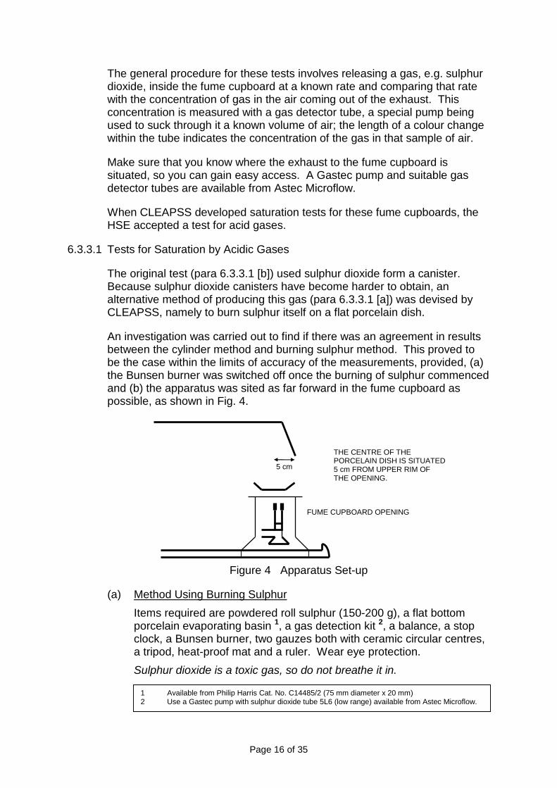
An investigation was carried out to find if there was an agreement in resultsbetween the cylinder method and burning sulphur method. This proved tobe the case within the limits of accuracy of the measurements, provided, (a)the Bunsen burner was switched off once the burning of sulphur commencedand (b) the apparatus was sited as far forward in the fume cupboard aspossible, as shown in Fig. 4.
Figure 4 Apparatus Set-up
(a) Method Using Burning Sulphur
Items required are powdered roll sulphur (150-200 g), a flat bottomporcelain evaporating basin 1, a gas detection kit 2, a balance, a stopclock, a Bunsen burner, two gauzes both with ceramic circular centres,a tripod, heat-proof mat and a ruler. Wear eye protection.
Sulphur dioxide is a toxic gas, so do not breathe it in.
THE CENTRE OF THEPORCELAIN DISH IS SITUATED5 cm FROM UPPER RIM OFTHE OPENING.
5 cm
FUME CUPBOARD OPENING
1 Available from Philip Harris Cat. No. C14485/2 (75 mm diameter x 20 mm)2 Use a Gastec pump with sulphur dioxide tube 5L6 (low range) available from Astec Microflow.

Page 17 of 35
Powder roll sulphur in a mortar with pestle.
Fill a flat-bottom porcelain basin with the sulphur so that it is level withthe rim.
Weigh the porcelain basin, tripod and other gauze on a heat-proof mat5 cm from the upper rim of the opening (see Fig. 4). (This places thesulphur in the maximum incoming draught and encourages completecombustion).
Place the basin with the sulphur on the tripod and gauze.
Switch on the fume cupboard.
Set the Bunsen alight with the gas tap half open and the collar openenough so that the flame is non-luminous. (The incoming draught mayrequire you to place the burner a little more forward than under thecentre of the basin; see Fig. 4).
The sulphur melts slowly to a pale amber liquid. Extreme care is nowrequired not to knock the tripod base with your hands or the Bunsenburner; molten sulphur can cause severe burns. Remove the Bunsenburner from under the gauze and open the collar so it is half open.Place it back under the gauze very carefully. (The liquid will quicklydarken. Changes in the appearance of the liquid surface indicate thatburning is about to start. Sulphur catches light with a blue flame.)
Start the stop clock when half of the surface of sulphur has caughtalight. Immediately switch off the Bunsen burner at the gas tap. (Theflame has two coloured areas, the inner brown flame of incompletecombustion and the outer blue flame of complete combustion.Switching off the Bunsen burner causes the area of brown flame todiminish leaving the blue flame).
After 60 seconds, take a reading of the concentration, the sulphurdioxide being emitted through the exhaust with a gas detection kit. (Aslight smell of sulphur dioxide should be ignored, but if the exhaust gascauses breathing difficulties, stop the test. The filter is obviouslyinefficient!)
Place the other gauze (which had been used in the weighing) on top ofthe basin and stop the clock, noting the time (in seconds). The gauzeputs out the flame but some sulphur condenses onto it, which is why itshould be included in the weighing).
When the sulphur has cooled down (allow 20 minutes) and solidified,re-weigh the basin, the remaining sulphur and the gauze (M2).
The sulphur and dish may be kept and used the next time the test iscarried out. A little more powdered roll sulphur may need to be addedto make up and lost in the previous burning
Calculation
Rate of sulphur dioxide released = (M1 - M2 x 750 cm3s-1)t
Now check your results with Table 1 in para 6.3.3.1 (c).

Page 18 of 35
(b) Method Using a Sulphur Dioxide Cylinder
You will need a gas detection kit, a sulphur dioxide canister (TOXIC), abalance, a stop clock plus the glassware shown in Fig. 5. Wear eyeprotection. Sulphur dioxide is a toxic gas, so do not breathe it in.
Figure 5 Sulphur Dioxide Method
(i) Find the mass of the sulphur dioxide cylinder (M1).
(ii) Set up the apparatus, as shown in Fig. 5, in the fume cupboard.Switch the fume cupboard on.
(iii) Open the valve on the gas canister very slowly. When bubblesappear in the measuring cylinder, start the stop clock. Adjust thevalve so that 100 ml of gas bubbles into the measuring cylinderduring a period of between 10 and 20 seconds.
(iv) Without touching the valve, disconnect the cylinder from theapparatus.
(v) After 60 seconds take a reading of the concentration of sulphurdioxide in the exhaust gas with the gas detection kit. (A slightsmell of sulphur dioxide should be ignored, but if the exhaust gascauses breathing difficulties, stop the test. The filter is obviouslyinefficient)!
(vi) Close the valve on the gas canister and stop the clock, noting thetime of the run (in seconds).
(vii) Find the mass of the sulphur dioxide cylinder (M2).
Calculation
Rate of sulphur dioxide released from the cylinder =
(M1 - M2) x 360 cm3s1
t
Now check your results with the Table 1.
SULPHURDIOXIDE
CANISTER
500 mlBOTTLE
100 mlMEASURINGCYLINDER
WATER
Page 19 of 35
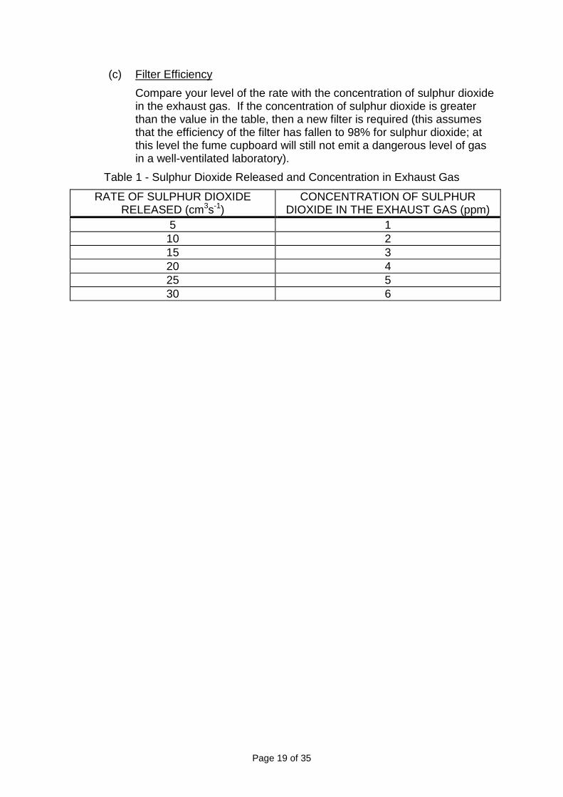
(c) Filter Efficiency
Compare your level of the rate with the concentration of sulphur dioxidein the exhaust gas. If the concentration of sulphur dioxide is greaterthan the value in the table, then a new filter is required (this assumesthat the efficiency of the filter has fallen to 98% for sulphur dioxide; atthis level the fume cupboard will still not emit a dangerous level of gasin a well-ventilated laboratory).
Table 1 - Sulphur Dioxide Released and Concentration in Exhaust Gas
RATE OF SULPHUR DIOXIDERELEASED (cm3s-1)
CONCENTRATION OF SULPHURDIOXIDE IN THE EXHAUST GAS (ppm)
5 110 215 320 425 530 6

Page 20 of 35
7 MAINTENANCE
Under the “Control of Substances Hazardous to Health” (COSHH)regulations, effective from 1st October 1989, it is mandatory to maintainwritten records of checks, test and repairs carried out on safety equipment,and these records must be kept for 5 years. A summary of COSHHregulations are provided in Appendix 1.
Regular maintenance will reduce the possibility of hazard to the operator andprolong the life of the fume cupboard.
WARNING:BEFORE ATTEMPTING ANY INSPECTION OR REPLACEMENT OFELECTRICAL COMPONENTS IN THE HEAD ASSEMBLY, ALWAYSISOLATE THE FUME CUPBOARD FROM THE MAINS ELECTRICITYSUPPLY.
7.1 AIRFLOW
The airflow indicator light will alarm the user to a low airflow situation.
This alarm should be tested and recalibrated if necessary, once a year asdescribed in Appendix 3.
It is advisable to manually check the airflow using an anemometer aspreviously described.
7.2 FILTER SATURATION
This should be tested as previously described at least once a year,preferably every term.
7.3 CLEANING AND INSPECTION
7.3.1 6 Monthly
The following procedures should be carried out at six monthly intervals:
(a) Remove the spillage tray (where fitted) and wash in dilute detergentsolution.
(b) Wash the interior surface of the cupboard with dilute detergent solution.
(c) Inspect the cupboard frame and panels for mechanical damage.
(d) Inspect the fan assembly for correct running by opening the bottom leftfront panel.
(e) The rear airflow distribution screen can be removed for cleaning ifrequired through the front aperture after removing the fixing screws.

Page 21 of 35
7.3.2 12 Monthly
The following checks should be carried out at 12 monthly intervals:
(a) Check the condition of services to the cupboard, including watersupply, drip cup, waste drain (where fitted), gas supply (where fitted)and electrical cable and plug.
(b) Check the condition of the filter and pre-filter.
7.3.3 24 Monthly
The following checks should be carried out at 24 monthly intervals.
The electrical earthing and insulation should be inspected by a qualifiedelectrician.
Page 22 of 35
8 TROUBLE SHOOTING
WARNING:BEFORE ATTEMPTING ANY INSPECTION OR REPLACEMENT OFELECTRICAL COMPONENTS IN THE HEAD ASSEMBLY, ALWAYSISOLATE THE FUME CUPBOARD FROM THE MAINS ELECTRICITYSUPPLY.
Electrical components are mounted on a plate in an electrical enclosurewhich is isolated from the airflow through the fume cupboard and isseparately vented to room air. Access to the electrical enclosure is throughthe cover on top of the unit.
Some possible problems and their causes are shown below:
(a) Unit will not operate, no lights or airflow:
(i) Check that the unit is plugged in and switched on.
(ii) Check the fuse in the mains supply or the plug (where fitted).
(iii) Check the fuses or circuit breakers in the head unit. The fuses orcircuit breakers are located next to the mains cable inlet.
(b) Unit operates, but one or both fluorescent lights do not come on:
(i) Check the circuit breaker.
(ii) Change the fluorescent light tube.
(iii) Replace the starter lamp in the electrical enclosure.
(c) Fan does not operate, but the lights come on:
(i) Check the circuit breaker.
(ii) Change the motor start capacitor in the electrical enclosure.
(iii) Motor failure - call Astec Microflow or local Service Engineer.
(d) Fan operates initially, but then cuts out. Lights remain on.
Motors are fitted with a thermal cut-out device, which will operate if themotor temperature rise exceeds 95C. The most likely cause ofoverheating is a blockage of the airflow, either at the filters or at theexhaust outlet at the bottom of the unit.
(e) The red indicator lamp comes on at switch on and stays on:
(i) The filter is not sealed correctly in the unit. Check the filter gasketis sealed correctly.
(ii) The fan has failed.
(iii) The alarm is malfunctioning see Appendix 3.

Page 23 of 35
(f) The red indicator lamp comes on at switch on, goes off, then comes onagain.
(i) The pre-filter is blocked with dust.
(ii) If replacement of the pre-filter does not cause the light to stay off,then the low airflow alarm requires recalibration, as described inAppendix 3.
(g) The red indicator light does not come on at switch on.
(i) The alarm requires recalibration, as described in Appendix 3.
(ii) If the fault persists after recalibration, there is a circuit failure.
Page 24 of 35
9 FILTER TYPES
9.1 PRE-FILTERS
Filtrete pre-filterThis is a high performance pre-filter, designed to remove particulates fromthe air stream. The filter material is based on electrets, which arepermanently charged di-electrics. They remove particulates from polluted airby strong electrostatic forces generated by the fibres from which they aremade.
The combination of strong electric charges and open structure provides afilter with high efficiency, low airflow resistance and high loading capacity.Measured efficiency figures for particles in the 0.5 - 2.0 micron is 99%, withloading capacities up to 113 g/m2. Filtrete will remove fine particles, aerosolsand mists.
9.2 MAIN FILTERS
A specially formulated activated carbon filter is produced for Schools use.The filter is manufactured with layers of carbon, which have beenimpregnated with chemicals for the neutralisation of specification fumes inthe schools curriculum. Typical efficiency guides of the filters are included inSection 10.
9.3 OTHER FILTERS
Other types of filters are available from Astec Microflow, after consultationwith Astec Microflow on the intended use.

Page 25 of 35
10 CHEMICAL APPLICATIONS
The multi filter is suitable for the chemical fumes released during normalschool activities. This includes:
CHEMICAL TYPICAL EFFICIENCY %
Ammonia 96
Sulphur Dioxide 98
Chlorine 98
Ethanol 99
Ethoxyethane 99
Methanol 99
Hydrogen Sulphide 97
Trichloroethane 99
Carbon Tetrachloride 99
Bromine 98
Sulphuric Acid 99
Hydrochloric Acid 99.5
Trichloroethylene 99
The filters are suitable for use with a wide range of other chemicals andadvice for specific application is available from Astec Microflow. Chemicalsgenerally used in schools for which the filters are suitable include:
ORGANIC INORGANIC
aluminium chloride and bromide acid amides
ammonia acid anhydrides
ammonium chloride fumes acid chlorides
bromine acidic nitrogen oxide
chlorine alcohols
chromium (VI) dichloride dioxide aldehydes
(chromyl chloride) aliphatic hydrocarbons
hydrogen sulphide aromatic amines and aromatic hydrocarbons
iodine aromatic nitro compounds
iodine chlorides carboxylic acids
lead fumes esters
lead bromide fumes ethers
mercury and its compound ketones
nitric acid vapour nitriles
nitrogen oxides organo halogens
phosphine phenols
phosphorus chlorides and bromides pyridine
phosphorus oxides
silicon tetrachloride Dusts, etc.
sulphur chlorides dyes
sulphur dioxide enzymes
thionyl chloride smoke
tin (IV) chloride
titanium tetrachloride
zinc chloride fumes
IT WILL NOT ABSORB HYDROGEN, CARBON MONOXIDE, NITROUSOXIDE OR METHANE

Page 26 of 35
APPENDIX 1 - NOTES ON COSHH REGULATIONS (UK ONLY)
1 The "Control of Substances Hazardous to Health" (COSHH) regulations,effective from 1st October 1989.
2 The regulations are the UK implementation of an EEC Council Directive80/1107/EEC.
3 The regulations require an employer to protect his employees and any otherpeople (whether working for him or not) from hazardous substances.
4 A hazardous substance is defined as:
(a) A substance that is on the list of hazardous substances as defined bythe Classification, Packaging and Labelling Regulations 1984 (b).
(b) A substance for which an Occupational Exposure Limit (OEL) valueexists. This list is similar to US Threshold Limit Value levels (TLV).
(c) A micro-organism which creates a health hazard.
(d) Dust at a substantial concentration in air.
(e) Any substance which creates a hazard to health, similar to the hazardscreated by the substances in (a) to (d).
Note:Paragraph 4 (e) is a "catch-all" section.
5 The employer is responsible for assessing the risk to an employee.
6 The employer must prevent or control the exposure of an employee tohazardous substances.
7 The control of exposure "shall be secured by measures other than theprovision of personal protective equipment". This means the fumes must becontained, rather than providing protective suits and masks to staff.
8 OEL values must not be exceeded.
9 The employer must ensure that safety equipment is properly used.
10 The employee must use safety equipment provided correctly.
11 The employer must maintain safety equipment in good working order; inparticular:
(a) Exhaust ventilation equipment must be examined every 14 months.
(b) Other safety equipment must be examined at "suitable intervals".
(c) Records of checks, tests and repairs must be kept for 5 years.
12 Monitoring of exposure to hazardous substances must occur "in accordancewith a suitable procedure". Records of results must be kept for 5 years forgeneral monitoring and for 30 years when they relate to a specific employee.

Page 27 of 35
13 Regular medical checks are required when working with certain listedsubstances, or where an identifiable disease is associated with a certainsubstance.
14 An employer must provide suitable instruction and training to employeesregarding risks of substances and precautions to be taken.
15 Certain other regulations take precedence, such as Control of Lead at Work,Control of Asbestos at Work, radioactive, explosive or flammableregulations, Mines and Quarries Act, and medical treatment regulations.

Page 28 of 35
APPENDIX 2 - ELECTRICAL DIAGRAM
ON/OFF
LIVE
230 V ac
2 AMP
EARTH
NEUTRAL
CAPACITOR
AUXILIARYPOWERSOCKET
CLOCK
PRESSURESWITCH
LOWAIRFLOW
ALARMLAMP
FAN
BR
OW
N
BLACK
BLUE
TWIN 18 WFLUORESCENTTUBE FITTING
Page 29 of 35
APPENDIX 3 - LOW AIRFLOW ALARM - TESTING AND CALIBRATING
WARNING:CALIBRATION OF THE PRESSURE SWITCHES INVOLVES REMOVING THECOVER OF THE ELECTRONIC ENCLOSURE, EXPOSING ELECTRICALCONTACTS AT MAINS VOLTAGE. THE PRESSURE SWITCHES ARE ALSOMAINS OPERATED. THE ADJUSTMENT MUST ONLY BE MADE BY ASUITABLY QUALIFIED PERSON, SUCH AS AN ELECTRICIAN OR INSTRUMENTTECHNICIAN.
1 TESTING THE LOW AIRFLOW ALARM
1.1 Ensure that new pre-filters are fitted in your filtration fume cupboard. Switchon the unit, indicator lamp should be out.
1.2 Switch off unit. Block the pre-filters to give an airflow of <0.3 m/s. Switchon. The red indicator lamp will start to flash.
1.3 If a malfunction is indicated by steps 1.1 or 1.2, then a pressure switchcalibration procedure may be required. Details are provided below.Remember to remove the plastic bags from the pre-filters before returningthe unit to routine use!
2 CALIBRATION PROCEDURE
2.1 The low airflow alarm operates using a differential pressure switch detects a‘high vacuum’ situation caused by a blocked pre-filter. The pressure switchis carefully calibrated before leaving our factory, and in the majority of casescalibration will not be required.
2.2 The factory calibration is carried out using a standard GP filter at 240, 220 or110 volts 50 Hz mains supply, depending on the market area. A standardFiltrete pre-filter is used. If the end-user is known (e.g. school) then thecalibration will be performed using the correct main filter in place (e.g. EDUfilter).
2.3 In some cases it may be necessary to recalibrate the pressure switch in thecustomer's laboratory if the test procedure described above fails. The mainreason for a test failure are:
(a) A severe knock during transport.
(b) A change in the mains voltage or frequency.
(c) Use of a different main filter from the used during factory calibration.
The pressure switch is located behind the control panel.
NOTE the warning at the top of this page concerning electrical hazards
2.4 The pressure switch is located by removing the grommet in the front controlpanel, and carefully inserting a screwdriver to locate the control screw.

Page 30 of 35
2.5 The filtration fume cupboard should be fitted with main filter and new Filtretepre-filter. Switch on. Wait 30 seconds to warm up.
2.6 Unscrew (anticlockwise) switch by 2 turns. The red warning light should nowbe off.
2.7 Screw switch clockwise until the red warning light JUST comes on.
2.8 Unscrew switch by 5 degree (half hour on the Hour hand of a clock) so thered warning light goes out.
2.9 Check calibration by switching the unit off, and wrap the pre-filter in a plasticbag and replace in the unit. Switch on. The warning light should come on.Remember to remove the plastic bag before returning to routine use!!
It should be noted that the alarm is NOT an ON/OFF device, but will start toflicker as the pre-filter progressively blocks with dust.

Page 31 of 35
APPENDIX 4 - FILTER SATURATION ALARM - TESTING AND CALIBRATION
1 TESTING
1.1 Switch on the unit, the green indicator lamp comes on.
1.2 Release the filter clamp.
1.3 Place a small amount of alcohol (isopropanol) on a tissue and hold abovethe filter to introduce the fume into the airstream. The red indicator lampshould come on and the audible alarm sound.
1.4 If a malfunction is indicated by steps 1.1 or 1.2, then a calibration proceduremay be required. Details are provided below. Remember to remove thetissue before returning to routine use!!
2 CALIBRATION
The detector has been set up in the factory before delivery. However theunit may require a slight adjustment in some environments.
2.1 Remove the Control Head.
2.2 The Gas Sensor Board is located adjacent to the Control Panel inside theControl Head.
2.3 Using a multimeter, monitor the voltage at the test point between the gassensor and the potentiometer and adjust to give 2.3 V.

Page 32 of 35
APPENDIX 5 – CARE AND CLEANING
1 STAINLESS STEEL COMPONENTS
Considerable care has been taken in the selection and processing of thestainless steel components used in the construction of this equipment,however even stainless steel can be damaged by chemical attack.
It is therefore important to ensure that any cleaning or disinfectingprocedures used will not cause a chemical attack that may damage thesurface of the stainless steel. Work surfaces should be kept clean and freeof chemical liquids, particularly those containing Chlorine.
Liquids or vapours containing Chlorine are known to cause gradual stainingof stainless steel. To avoid this, when chemicals are used containingChlorine all surfaces should be thoroughly dried and all traces of the solutionremoved, the area should then be treated with a neutralising agent. Openvessels left inside the equipment which are likely to cause Chlorine vapoursmay also result in staining of the metal surfaces.
Should the surface of the stainless steel become stained, it may be cleanedby mechanical polishing and special treatment of the affected area. Ourservice department can help with this process.
2 PLASTIC COMPONENTS
Cleaning of the plastic items should only be carried out with mild detergentor chlorine based cleaning solutions. Care must be taken not to applychlorine solutions to any stainless steel metalwork, as this will potentiallycause staining.
Do not apply heat, abrasive materials, solvents or solvent wipes to thesurface as this can cause irreparable damage.
3 PAINTED AND OTHER COMPONENTS
Caution:Do not use water around electrical connections, switches etc.
To clean all painted and other components use a damp cloth and, whenrequired, a liquid detergent.
Note:Do not use abrasive cleaners or chlorine based cleaning products.

Page 33 of 35
APPENDIX 6 – CE CERTIFICATE
Page 34 of 35
APPENDIX 7 WARRANTY INFORMATION
BIOQUELL UK Ltd. produces products that are warranted under normal usageagainst defects in workmanship and materials for one-year parts and labourcosts, from the date of manufacture. The Warranty is stated in the StandardTerms and Conditions of sale.
Export and Agent retailed products are warranted directly by the Agent. Pleaseconfirm your warranty and liability status with the Agent.
In addition, the Warranty is void unless the following conditions are met:
(a) The product has been installed and used as stated within the InstructionManual.
(b) TThhee wwaarrrraannttyy ddooeess NNOOTT iinncclluuddee sseerrvviicciinngg oorr mmaaiinntteennaannccee.. An approvedservice company who have attended our training courses for your productmust carry out maintenance of product. Failure to maintain or service thisproduct will invalidate the warranty. Maintenance must be carried out inaccordance with the Service Manual and include tasks within stated periods.Failure to use approved service companies or BIOQUELL UK Ltd. trainedpersonnel for maintenance also affects the CE Marking status of the product,removing BIOQUELL’s Duty of Care and responsibility
(c) Consumables such as: pre-filters, main filters, light bulbs and tubes, notwarranted.
(d) This Warranty is void if faults are caused by accidental damage,mishandling, adjustment by unauthorised personnel or failure to follow thecorrect maintenance and safety precautions as stated in the InstructionManual.
(e) The Warranty expressly provided for herein is the sole Warranty provided inconnection with the product and no other Warranty, expressed or implied, isprovided. BIOQUELL UK Ltd. assumes no responsibility for any otherclaims, consequential (including lost time or profit) or other damage, whetherbased in contract, tort or otherwise, not specifically stated in this Warranty.
(f) Except in respect of death or personal injury caused by Seller’s negligence,or as expressly provided in these Conditions, Seller shall not be liable toBuyer by reason of any representation (unless fraudulent), or any impliedwarranty, condition or other term, or any duty at common law, or under theexpress terms of the Contract for any loss of profit or any indirect, special orconsequential loss, damage, costs, expenses or other claims (whethercaused by the negligence of Seller, its servants or agents or otherwise)which arise out of or in connection with the supply of the Goods or their useor resale by Buyer, and the entire liability of Seller under or in connectionwith the Contract shall not exceed the price of the Goods.

Page 35 of 35
Note:
When requesting a Warranty visit, please have the following information available:
(i) Product model number and name.
(ii) Serial number.
(iii) Date of last service, and Service Company.
(iv) Nature of fault and any other comments likely to indicate cause of fault.
(v) A Purchase Order number to cover costs incurred if visit is outside the scopeof the Warranty.
BIOQUELL UK Ltd., or other nominated personnel will carry out warranty visits.
(g) In the event of any health and safety incidents please advise us in writing atthe earliest opportunity.
(h) This warranty and all other contractual issues shall be governed by Englishlaw and the parties agree to submit to the nonexclusive jurisdiction of thecourts of England.


![ASTEC Software System - IRSN · Safety of nuclear facilities and systems ASTEC Software System [SIMULATION OF CORE MELTDOWN ACCIDENTS] The software system ASTEC - Accident Source](https://img.dokumen.tips/doc/110x75/5fd36c840b38346a0c0a376e/astec-software-system-irsn-safety-of-nuclear-facilities-and-systems-astec-software.jpg)