Embed Size (px)
Citation preview
Fluidized Bed Concentratorfor VOC Abatementfor VOC Abatement
AgendaAgenda
1) Introduction of Technology2) Running/Maintenance of Equipment
Fluidized Bed VOC Abatement System
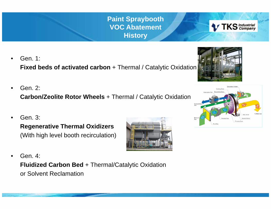
Paint Spraybooth VOC Abatement
History
• Gen. 1: Fi d b d f ti t d b Th l / C l i O id i
y
Fixed beds of activated carbon + Thermal / Catalytic Oxidation
• Gen. 2: Carbon/Zeolite Rotor Wheels + Thermal / Catalytic Oxidation
• Gen 3:• Gen. 3: Regenerative Thermal Oxidizers(With high level booth recirculation)
• Gen. 4:Fluidized Carbon Bed + Thermal/Catalytic Oxidation or Solvent Reclamation
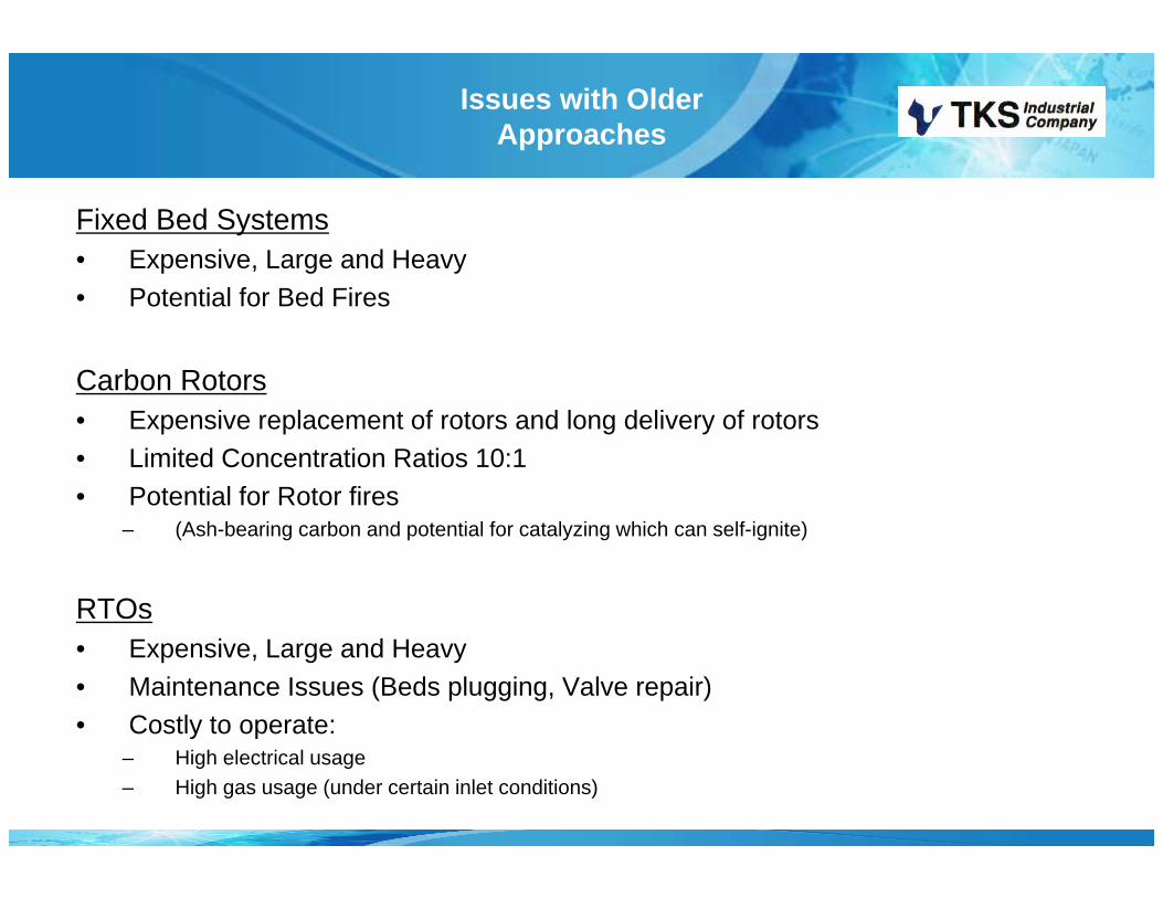
Issues with Older Approaches
Fixed Bed Systems• Expensive, Large and Heavy• Potential for Bed Fires
Carbon Rotors• Expensive replacement of rotors and long delivery of rotors• Limited Concentration Ratios 10:1 • Potential for Rotor fires
– (Ash-bearing carbon and potential for catalyzing which can self-ignite)
RTOs• Expensive, Large and Heavy• Maintenance Issues (Beds plugging, Valve repair)• Costly to operate:Costly to operate:
– High electrical usage– High gas usage (under certain inlet conditions)
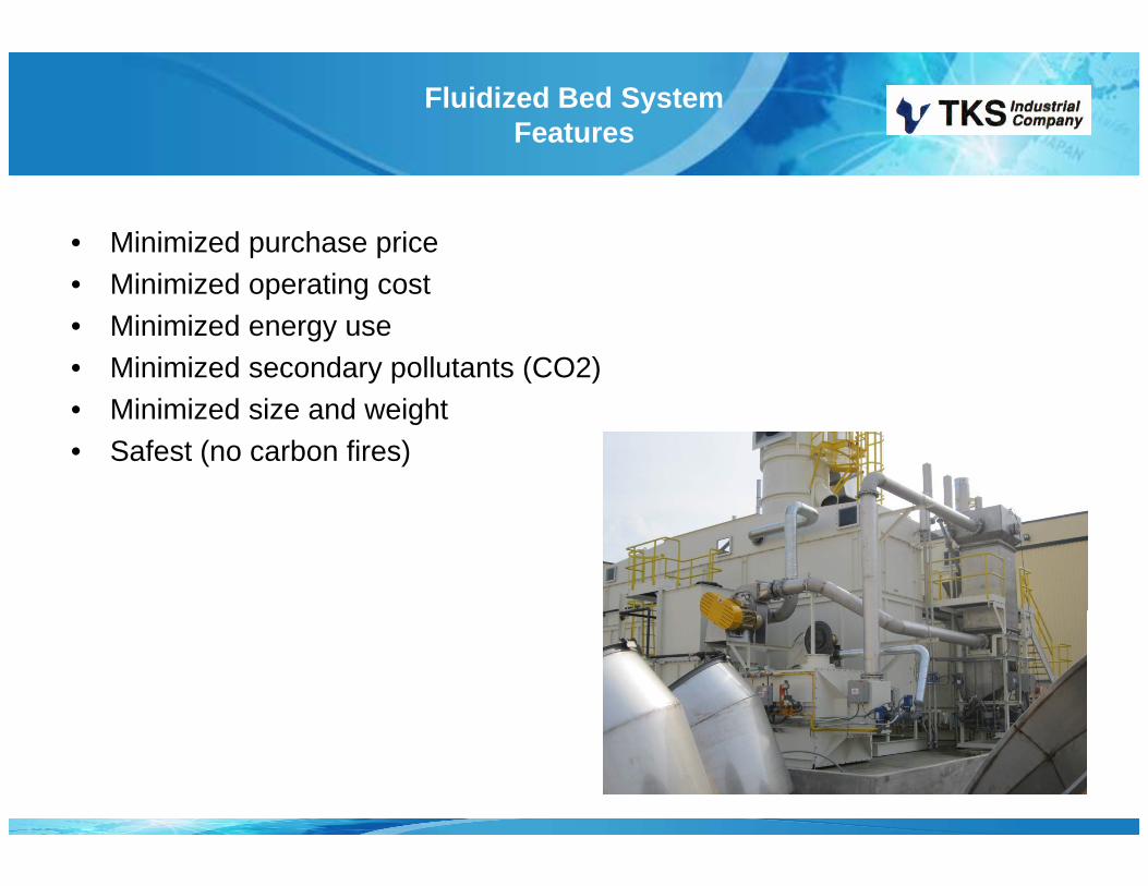
Fluidized Bed System Features
• Minimized purchase priceMi i i d ti t• Minimized operating cost
• Minimized energy use • Minimized secondary pollutants (CO2) • Minimized size and weight • Safest (no carbon fires)
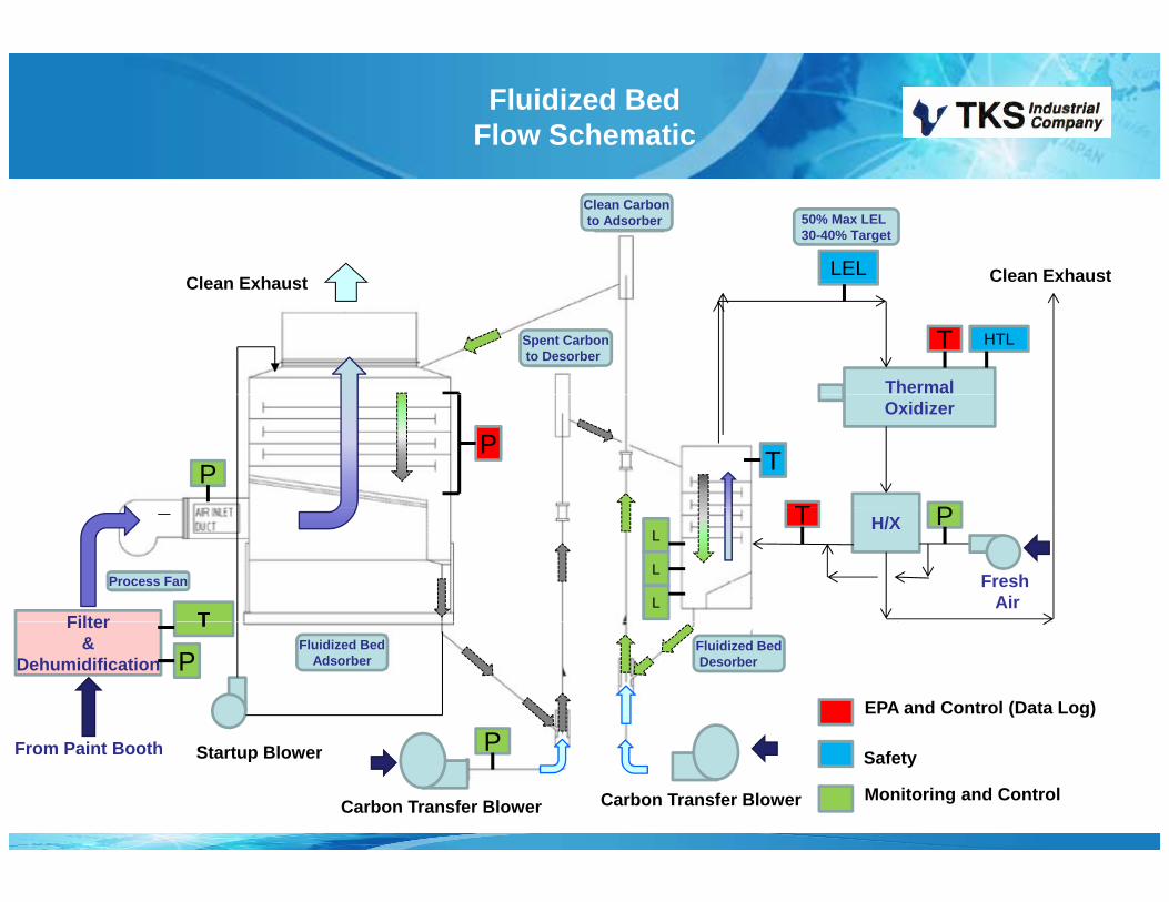
Fluidized Bed Flow Schematic
Clean Exhaust Clean ExhaustLEL
Clean Carbonto Adsorber 50% Max LEL
30-40% Target
Clean Exhaust
Thermal
Clean Exhaust
T HTLSpent Carbonto Desorber
CleanExhaust LEL Monitor
Desorber Ductto Thermal Oxidizer
Oxidizer
PP
T
T
P
Filter
H/X
Fresh Air
T
TL
L
L
P
Process Fan
Filter&
DehumidificationThermal OxidizerHot gas from
Thermal OxidizerPT
PEPA and Control (Data Log)
Fluidized BedAdsorber
Fluidized BedDesorber
From Paint Booth PSafety
Monitoring and Control
Startup Blower
Carbon Transfer Blower Carbon Transfer Blower
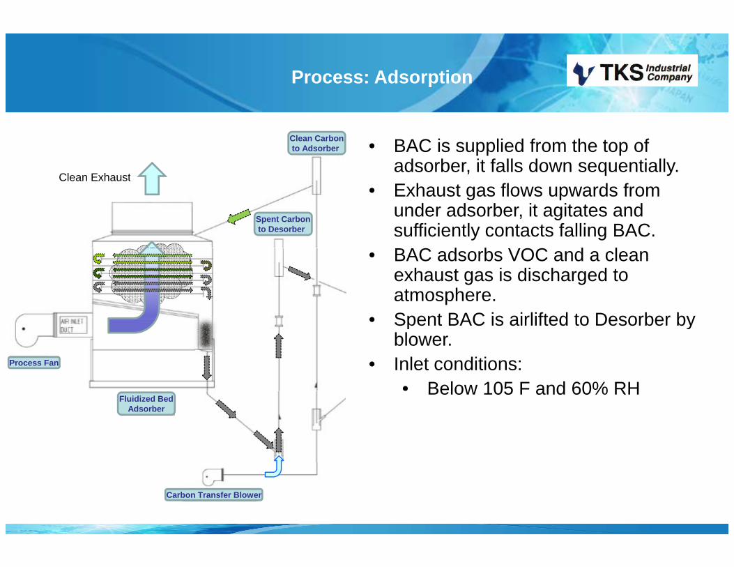
Process: Adsorption
Clean Exhaust
• BAC is supplied from the top of adsorber, it falls down sequentially.
Clean Carbonto Adsorber
Clean Exhaust• Exhaust gas flows upwards from
under adsorber, it agitates and sufficiently contacts falling BAC. BAC d b VOC d l
Spent Carbonto Desorber
• BAC adsorbs VOC and a clean exhaust gas is discharged to atmosphere.
• Spent BAC is airlifted to Desorber by• Spent BAC is airlifted to Desorber by blower.
• Inlet conditions:• Below 105 F and 60% RH
Process Fan
Below 105 F and 60% RHFluidized Bed
Adsorber
Carbon Transfer Blower
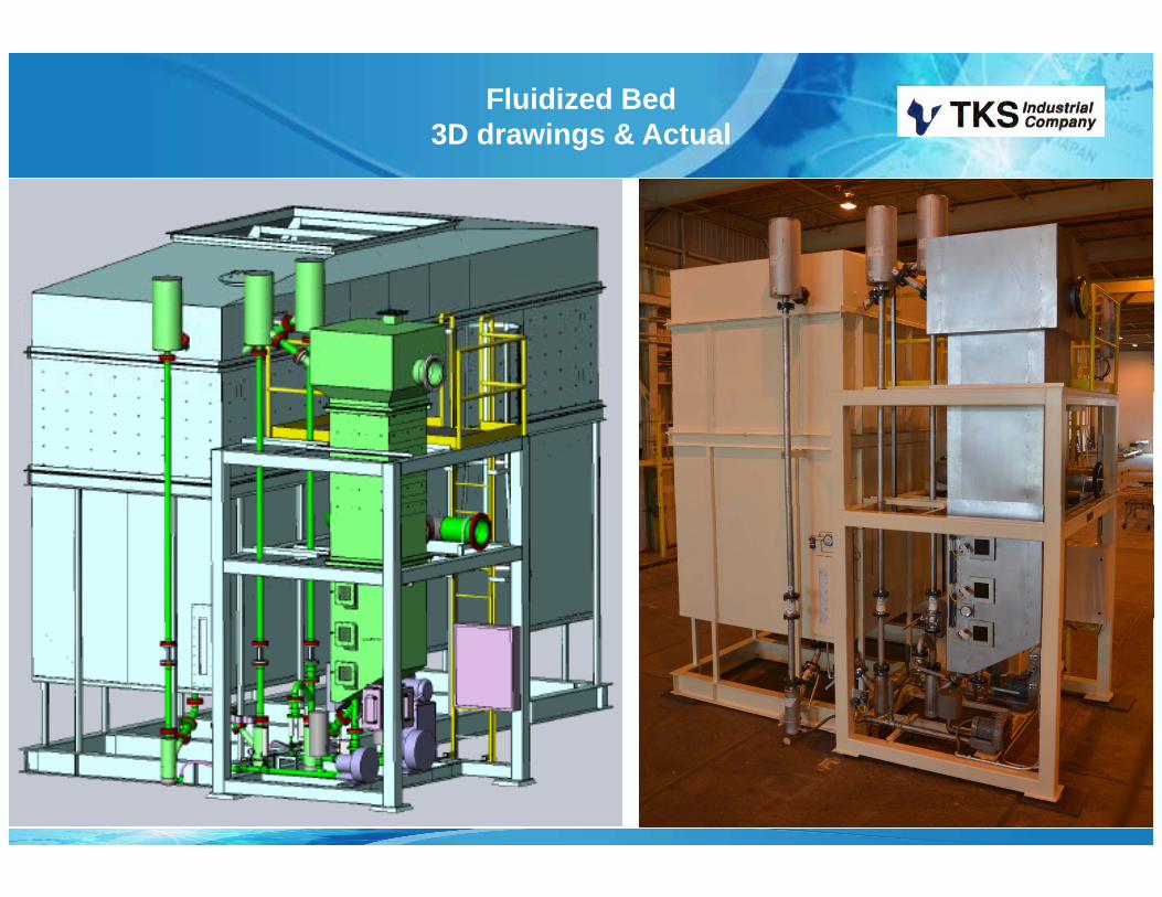
Fluidized Bed 3D drawings & Actual

Fluidized Bed 3D drawings & Actual
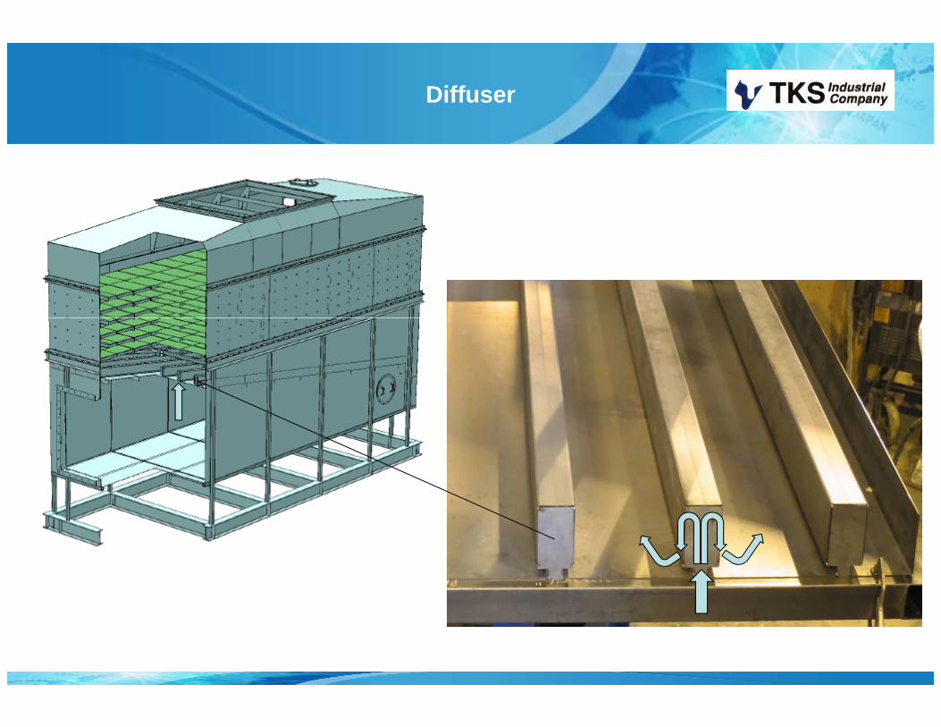
Diffuser
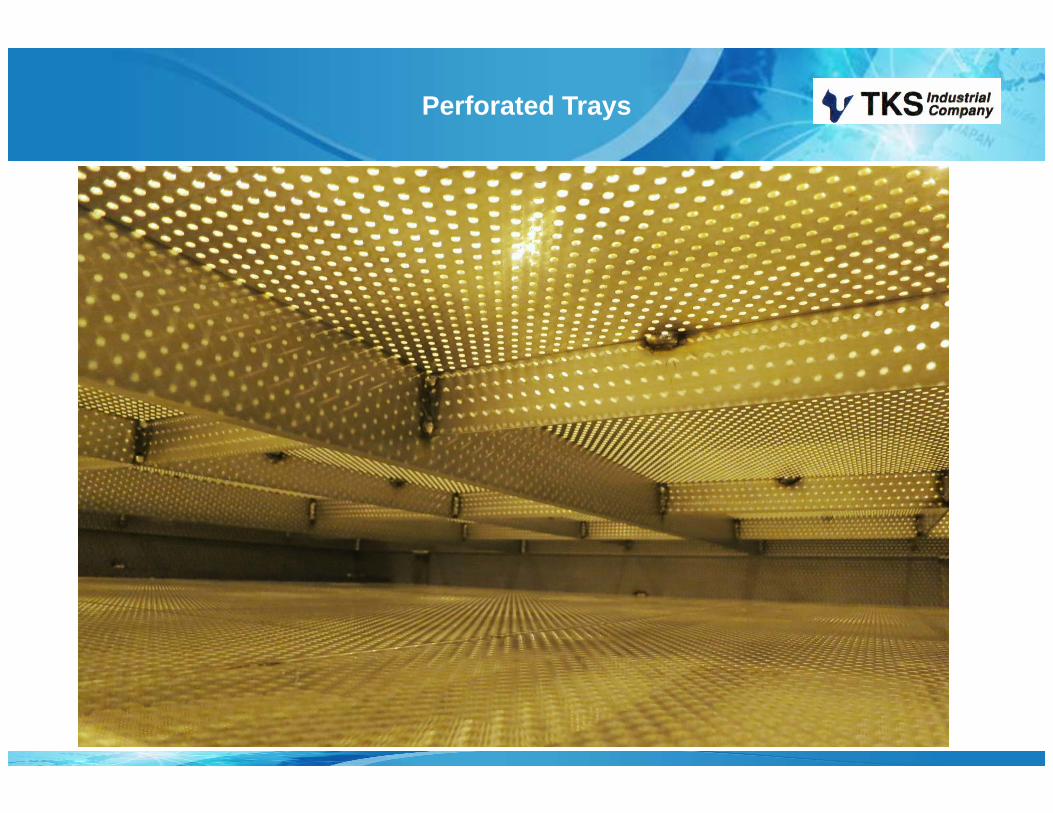
Perforated Trays
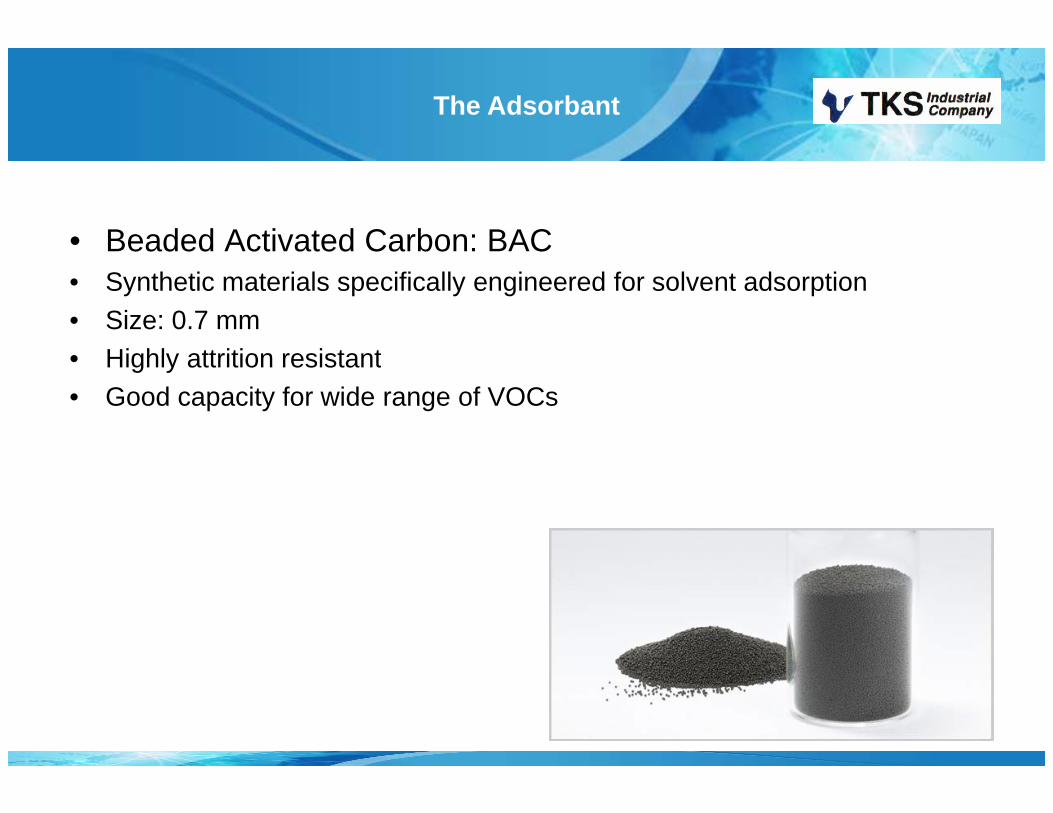
The Adsorbant
• Beaded Activated Carbon: BAC• Synthetic materials specifically engineered for solvent adsorption• Size: 0.7 mm• Highly attrition resistant• Highly attrition resistant• Good capacity for wide range of VOCs
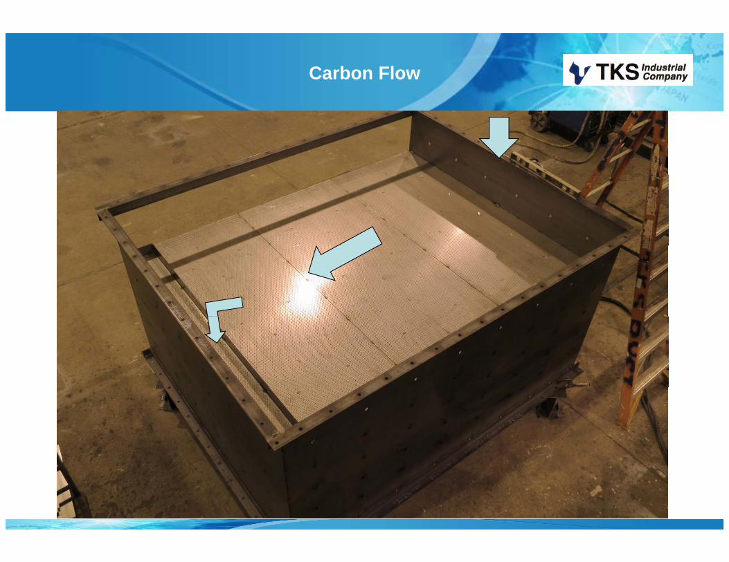
Carbon Flow

Six Adsorbing Trays
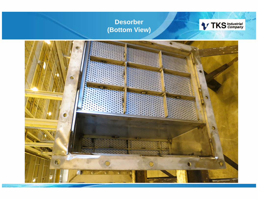
Desorber(Bottom View)

Process: Desorption
• Spent BAC from adsorber is airlifted to top of Desorber.
• Carbon is heated in passage through• Carbon is heated in passage through desorber to remove concentrated VOCs.
• Low volume carrier gas passesLow volume carrier gas passes through desorber to purge desorbate.
• Desorbate is piped out of Desorber to final treatment device.
Process: Desorption
• Strips VOCs from the Carbon• Desorber heated using Oxidizer’s exhaust• Set point: 350 °F (177 )
O ti R 325 425 °F (163 218 )• Operating Range: 325 - 425 °F (163 - 218 )
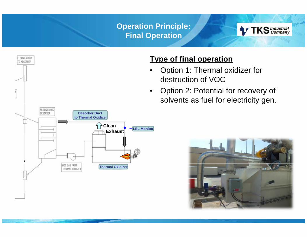
Operation Principle:Final Operation
Type of final operation• Option 1: Thermal oxidizer for p
destruction of VOC • Option 2: Potential for recovery of
solvents as fuel for electricity gen.y g
CleanExhaust LEL Monitor
Desorber Ductto Thermal Oxidizer
Thermal Oxidizer
Process: Oxidizer
• Oxidizer destroys the VOCs• High temperature is required to initiate the reaction• Higher temperature potentially destroys more VOC’s• Planned Set point: 1500 °F ( 815 )• Planned Set point: ~1500 F (~ 815 )
Concentration Ratio
• Systems have been built at as high as 14000:1 turndown (Process gas versus Final desorbate stream volume)(Process gas versus Final desorbate stream volume)
• Typical for oxidation is 30:1 to 70:1 (air desorption)• Typical for condensation/fuel for electricity is 1200:1 turndown
(nitrogen desorption)• Meets all US safety Codes for Fire, Electrical
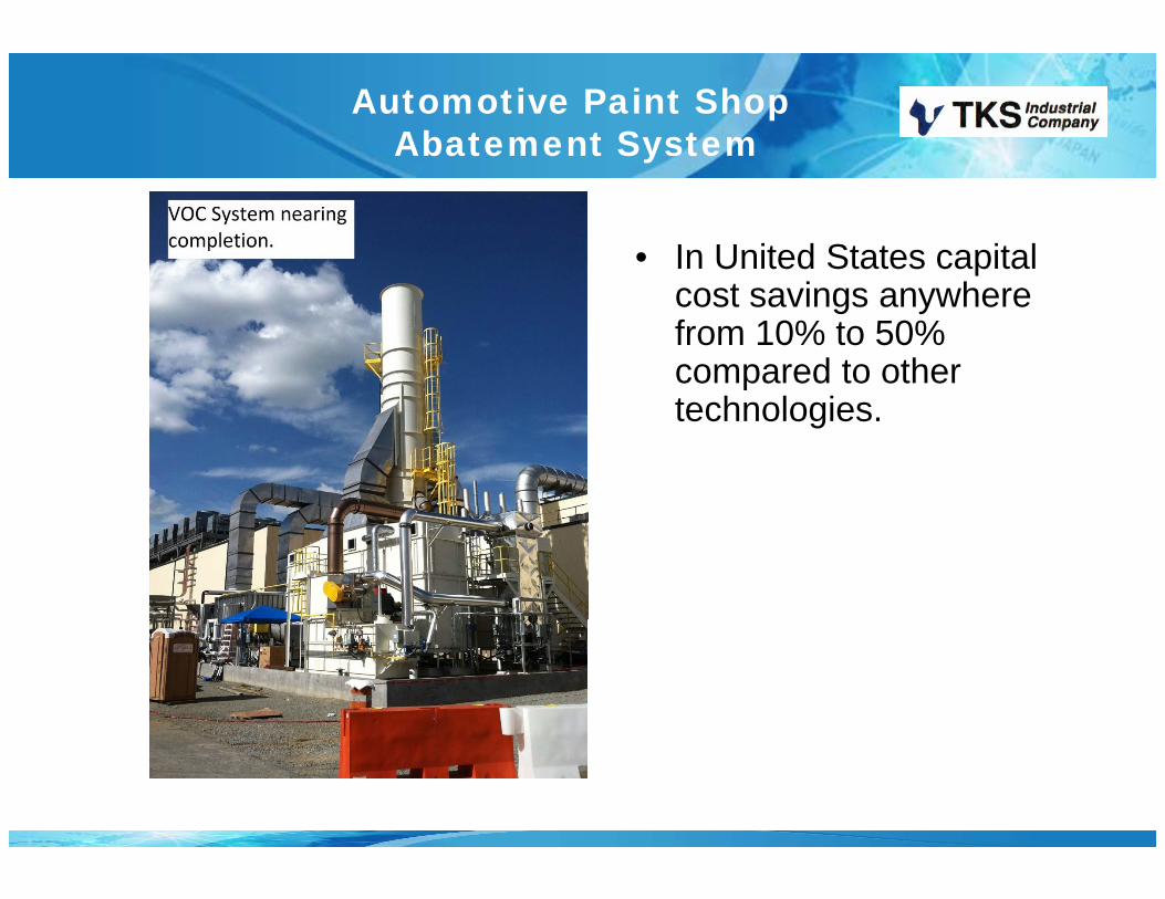
Automotive Paint Shop Abatement System
• In United States capital cost savings anywhere from 10% to 50% compared to other technologies.
FBC SystemAutomotive Installations
Toyota HondaToyota Honda

Size and Weight
T h l Si F t i t W i ht L dTechnology Size (m3/min)
Footprint (sq m)
Weight (kg)
Load(kg/sq m)
FBC 2832 130 46,363 380
Zeolite Rotor/RTO 2832 200 89,450 662
RTO 2832 280 170,455 3012
Does not include:• Process fan• Process ducts• Exhaust Stack• Filter house and Dehumidification

Materials to avoid with FBC
• Halogenated Solvents (Trichloroethylene, 1,1,1 Trichloroethane Carbon Tetrachloride etc )Trichloroethane, Carbon Tetrachloride, etc.)
• Oil Mists (Emulsions, etc.)• Styrenes (ethenylbenzene, vinyl benzene, phenylethene, etc)

Energy Consumption
• Adsorber pressure drop is typically about 3.5 to 4.5 in. waterp p yp yThis minimizes fan power requirements.
• The desorber uses waste heat from the oxidizer for thermal regeneration needs further reducing energy consumptionregeneration needs, further reducing energy consumption.
• The high VOC concentration ratio results in minimized need for supplemental oxidizer fuel.
Applications
• Ideally suited to high exhaust flow with low VOC y gconcentrations.
• Also good for lower flows, such as SVE vent gas or other di ti kremediation work.
• Less susceptible to particulate problems.
Experience
• Installations include:– Painting subcontractor to GM– FordFord– Toyota,– Honda,
Chrysler;– Chrysler; – US military special paint operations; – structural steel painting;
spray drying operations;– spray drying operations; – cosmetics production;
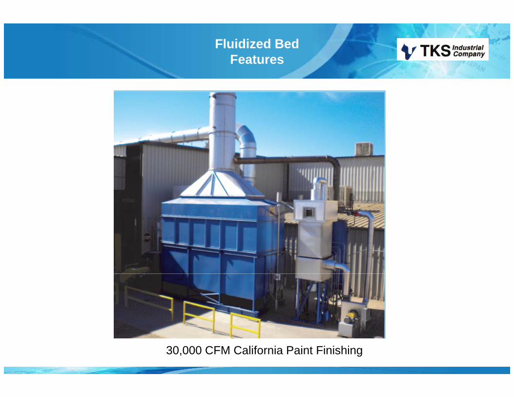
Fluidized Bed Features
30,000 CFM California Paint Finishing

156,000 CFM Unit

156,000 CFM Unit
Inlet air Filtration
Desorption/Oxidation system
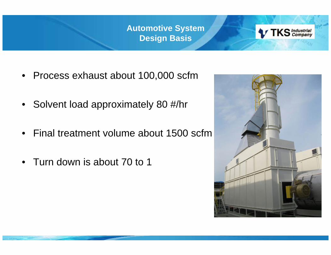
Automotive SystemDesign Basis
• Process exhaust about 100,000 scfm,
• Solvent load approximately 80 #/hr
• Final treatment volume about 1500 scfm
• Turn down is about 70 to 1
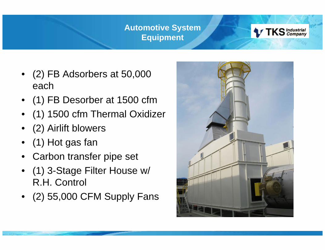
Automotive System Equipment
• (2) FB Adsorbers at 50,000 ( ) ,each
• (1) FB Desorber at 1500 cfm• (1) 1500 cfm Thermal Oxidizer• (2) Airlift blowers
(1) Hot gas fan• (1) Hot gas fan• Carbon transfer pipe set• (1) 3-Stage Filter House w/(1) 3 Stage Filter House w/
R.H. Control• (2) 55,000 CFM Supply Fans

Automotive System Equipment
• Running since July 2012g y• Carbon reactivated December
2012 and Dec. 2013• Overall efficiency 95%+• Customer experienced 60%
reduction in energy use andreduction in energy use and CO2 emissions.

FBC SystemInstallations
Customer Airflow Solvent InstalledCusto e o So e t sta ed1) **Sony Music (See Unit #32) 10,760 cfm (305 m3/min) THF 1979
Magnetic Tape Mfg., GA2) **Monsanto (NutraSweet Kelco) 22,000 cfm (623 m3/min) Isopropanol 1982
Food Processing, OK3) **Logan Aluminum – Russellville, KY 34,000 cfm (962 m3/min) Kerosene 1985
CM-2 Cold Aluminum Rolling Mill Mineral Sprits4) **Logan Aluminum – Russellville, KY 105,000 cfm (2972 m3/min) Kerosene 1985
CM-1 Cold Aluminum Rolling Mill Mineral Sprits5) Dana Everflex 1,800 cfm (51 m3/min) Perchloroethylene 1993
Teflon Hose Mfg., Ludlow, MA6) *Semiconductor Mfg OR (#1) 1 800 cfm (51 m3/min) Mixed solvents 19946) Semiconductor Mfg., OR (#1) 1,800 cfm (51 m3/min) Mixed solvents 19947) *Semiconductor Mfg., OR (#2) 20,000 cfm (566 m3/min) Mixed solvents 19968) Komag Hard Disk Mfg., CA (#1) 600 cfm (17 m3/min) Mixed solvents 19969) Komag Hard Disk Mfg., CA (#2) 1,000 cfm (28 m3/min) Mixed solvents 199710) *Semiconductor Mfg., NM (#1) 4,500 cfm (127 m3/min) Mixed solvents 199711) *Semiconductor Mfg., NM (#2) 4,500 cfm (127 m3/min) Mixed solvents 1997) g , ( ) , ( )12) *Semiconductor Mfg., Israel (#1) 20,000 cfm (566 m3/min) Mixed solvents 199713) *Semiconductor Mfg., Israel (#2) 20,000 cfm (566 m3/min) Mixed solvents 199714) *Semiconductor Mfg., Ireland 25,000 cfm (566 m3/min) Mixed solvents 199715) *Semiconductor Mfg., AZ
(See Unit #37) 36,000 cfm (1019 m3/min) Mixed solvents 1998
FBC SystemInstallations
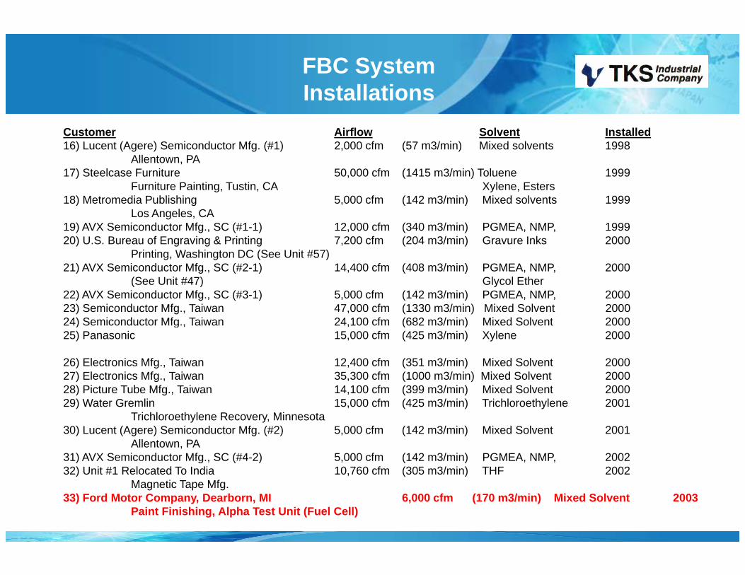
Customer Airflow Solvent Installed 16) Lucent (Agere) Semiconductor Mfg. (#1) 2,000 cfm (57 m3/min) Mixed solvents 1998
Allentown, PA 17) Steelcase Furniture 50,000 cfm (1415 m3/min) Toluene 1999
Furniture Painting, Tustin, CA Xylene, Esters18) Metromedia Publishing 5,000 cfm (142 m3/min) Mixed solvents 1999
Los Angeles, CA 19) AVX Semiconductor Mfg., SC (#1-1) 12,000 cfm (340 m3/min) PGMEA, NMP, 199920) U.S. Bureau of Engraving & Printing 7,200 cfm (204 m3/min) Gravure Inks 2000
P i ti W hi t DC (S U it #57)Printing, Washington DC (See Unit #57)21) AVX Semiconductor Mfg., SC (#2-1) 14,400 cfm (408 m3/min) PGMEA, NMP, 2000
(See Unit #47) Glycol Ether22) AVX Semiconductor Mfg., SC (#3-1) 5,000 cfm (142 m3/min) PGMEA, NMP, 200023) Semiconductor Mfg., Taiwan 47,000 cfm (1330 m3/min) Mixed Solvent 2000 24) Semiconductor Mfg Taiwan 24 100 cfm (682 m3/min) Mixed Solvent 200024) Semiconductor Mfg., Taiwan 24,100 cfm (682 m3/min) Mixed Solvent 200025) Panasonic 15,000 cfm (425 m3/min) Xylene 2000
26) Electronics Mfg., Taiwan 12,400 cfm (351 m3/min) Mixed Solvent 200027) Electronics Mfg., Taiwan 35,300 cfm (1000 m3/min) Mixed Solvent 200028) Picture Tube Mfg., Taiwan 14,100 cfm (399 m3/min) Mixed Solvent 200029) Water Gremlin 15,000 cfm (425 m3/min) Trichloroethylene 2001
Trichloroethylene Recovery, Minnesota30) Lucent (Agere) Semiconductor Mfg. (#2) 5,000 cfm (142 m3/min) Mixed Solvent 2001
Allentown, PA 31) AVX Semiconductor Mfg., SC (#4-2) 5,000 cfm (142 m3/min) PGMEA, NMP, 200232) Unit #1 Relocated To India 10 760 cfm (305 m3/min) THF 200232) Unit #1 Relocated To India 10,760 cfm (305 m3/min) THF 2002
Magnetic Tape Mfg.33) Ford Motor Company, Dearborn, MI 6,000 cfm (170 m3/min) Mixed Solvent 2003
Paint Finishing, Alpha Test Unit (Fuel Cell)
FBC SystemInstallations
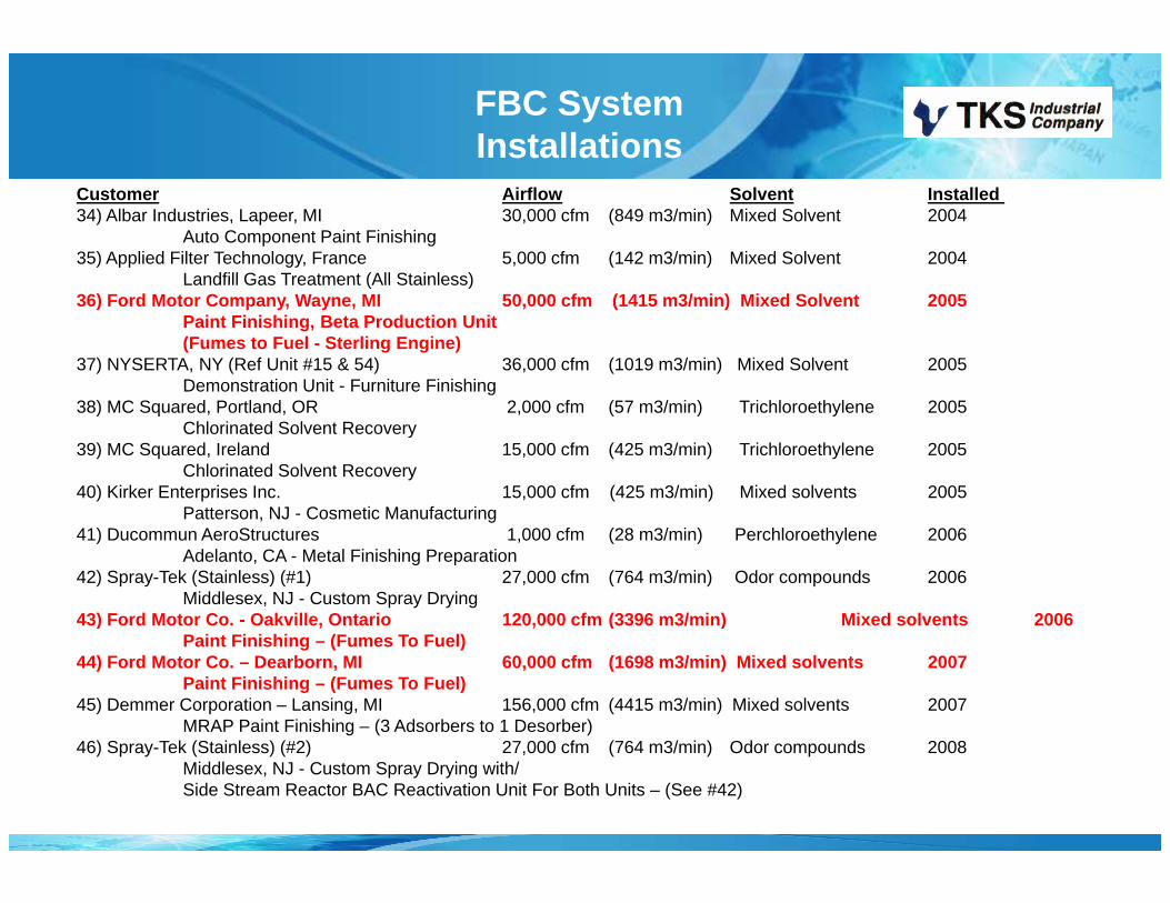
Customer Airflow Solvent Installed 34) Albar Industries, Lapeer, MI 30,000 cfm (849 m3/min) Mixed Solvent 2004
Auto Component Paint Finishing35) Applied Filter Technology, France 5,000 cfm (142 m3/min) Mixed Solvent 2004
Landfill Gas Treatment (All Stainless)Landfill Gas Treatment (All Stainless)36) Ford Motor Company, Wayne, MI 50,000 cfm (1415 m3/min) Mixed Solvent 2005
Paint Finishing, Beta Production Unit (Fumes to Fuel - Sterling Engine)
37) NYSERTA, NY (Ref Unit #15 & 54) 36,000 cfm (1019 m3/min) Mixed Solvent 2005Demonstration Unit - Furniture Finishingg
38) MC Squared, Portland, OR 2,000 cfm (57 m3/min) Trichloroethylene 2005Chlorinated Solvent Recovery
39) MC Squared, Ireland 15,000 cfm (425 m3/min) Trichloroethylene 2005Chlorinated Solvent Recovery
40) Kirker Enterprises Inc. 15,000 cfm (425 m3/min) Mixed solvents 2005P tt NJ C ti M f t iPatterson, NJ - Cosmetic Manufacturing
41) Ducommun AeroStructures 1,000 cfm (28 m3/min) Perchloroethylene 2006Adelanto, CA - Metal Finishing Preparation
42) Spray-Tek (Stainless) (#1) 27,000 cfm (764 m3/min) Odor compounds 2006Middlesex, NJ - Custom Spray Drying
43) Ford Motor Co - Oakville Ontario 120 000 cfm (3396 m3/min) Mixed solvents 200643) Ford Motor Co. Oakville, Ontario 120,000 cfm (3396 m3/min) Mixed solvents 2006Paint Finishing – (Fumes To Fuel)
44) Ford Motor Co. – Dearborn, MI 60,000 cfm (1698 m3/min) Mixed solvents 2007Paint Finishing – (Fumes To Fuel)
45) Demmer Corporation – Lansing, MI 156,000 cfm (4415 m3/min) Mixed solvents 2007MRAP Paint Finishing – (3 Adsorbers to 1 Desorber)
46) Spray-Tek (Stainless) (#2) 27,000 cfm (764 m3/min) Odor compounds 2008Middlesex, NJ - Custom Spray Drying with/Side Stream Reactor BAC Reactivation Unit For Both Units – (See #42)
FBC SystemInstallations
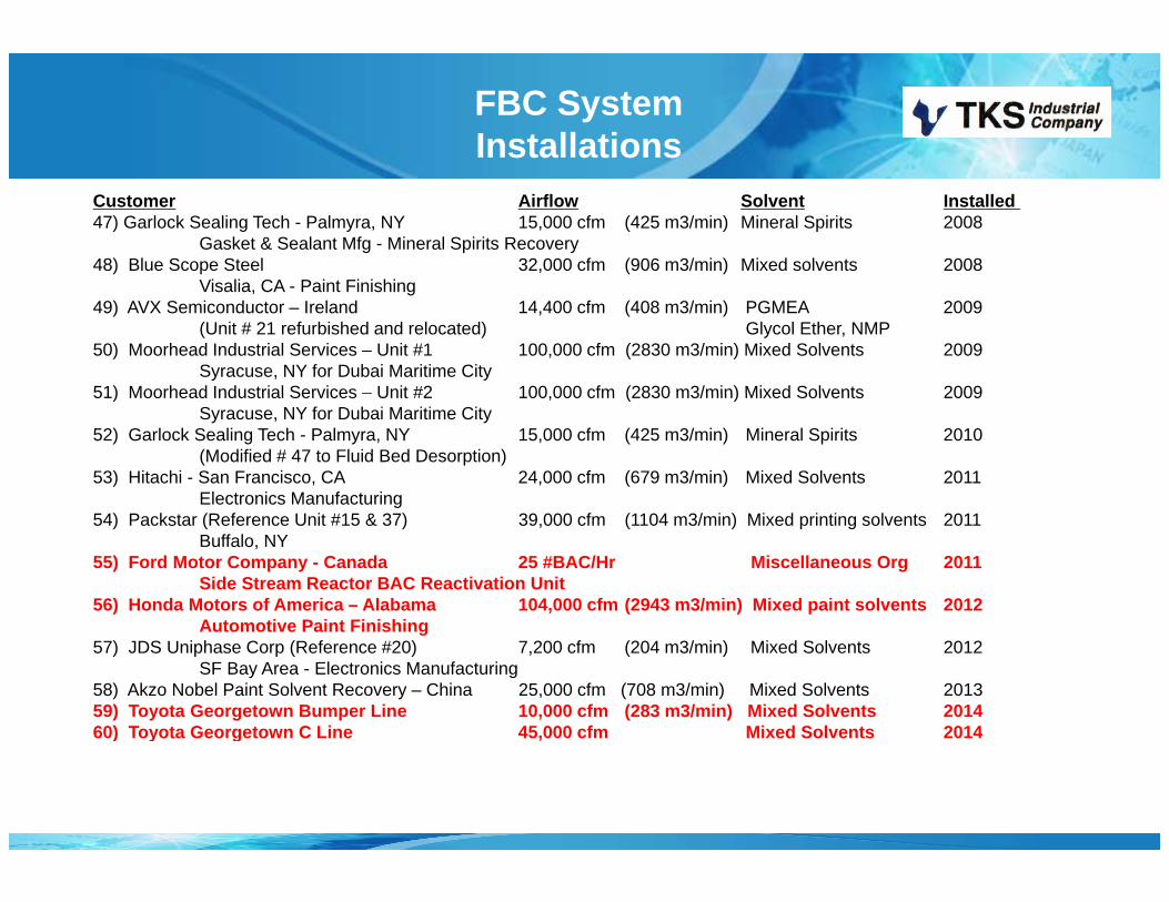
Customer Airflow Solvent Installed 47) Garlock Sealing Tech - Palmyra, NY 15,000 cfm (425 m3/min) Mineral Spirits 2008
Gasket & Sealant Mfg - Mineral Spirits Recovery 48) Blue Scope Steel 32,000 cfm (906 m3/min) Mixed solvents 2008
Vi li CA P i t Fi i hiVisalia, CA - Paint Finishing49) AVX Semiconductor – Ireland 14,400 cfm (408 m3/min) PGMEA 2009
(Unit # 21 refurbished and relocated) Glycol Ether, NMP50) Moorhead Industrial Services – Unit #1 100,000 cfm (2830 m3/min) Mixed Solvents 2009
Syracuse, NY for Dubai Maritime City 51) Moorhead Industrial Services – Unit #2 100 000 cfm (2830 m3/min) Mixed Solvents 200951) Moorhead Industrial Services Unit #2 100,000 cfm (2830 m3/min) Mixed Solvents 2009
Syracuse, NY for Dubai Maritime City 52) Garlock Sealing Tech - Palmyra, NY 15,000 cfm (425 m3/min) Mineral Spirits 2010
(Modified # 47 to Fluid Bed Desorption)53) Hitachi - San Francisco, CA 24,000 cfm (679 m3/min) Mixed Solvents 2011
Electronics Manufacturing 54) Packstar (Reference Unit #15 & 37) 39,000 cfm (1104 m3/min) Mixed printing solvents 2011
Buffalo, NY55) Ford Motor Company - Canada 25 #BAC/Hr Miscellaneous Org 2011
Side Stream Reactor BAC Reactivation Unit56) Honda Motors of America – Alabama 104,000 cfm (2943 m3/min) Mixed paint solvents 2012
A t ti P i t Fi i hiAutomotive Paint Finishing57) JDS Uniphase Corp (Reference #20) 7,200 cfm (204 m3/min) Mixed Solvents 2012
SF Bay Area - Electronics Manufacturing 58) Akzo Nobel Paint Solvent Recovery – China 25,000 cfm (708 m3/min) Mixed Solvents 201359) Toyota Georgetown Bumper Line 10,000 cfm (283 m3/min) Mixed Solvents 201460) Toyota Georgetown C Line 45,000 cfm Mixed Solvents 201460) Toyota Georgetown C Line 45,000 cfm Mixed Solvents 2014
AgendaAgenda
1) Introduction of Technology2) Running/Maintenance of Equipment
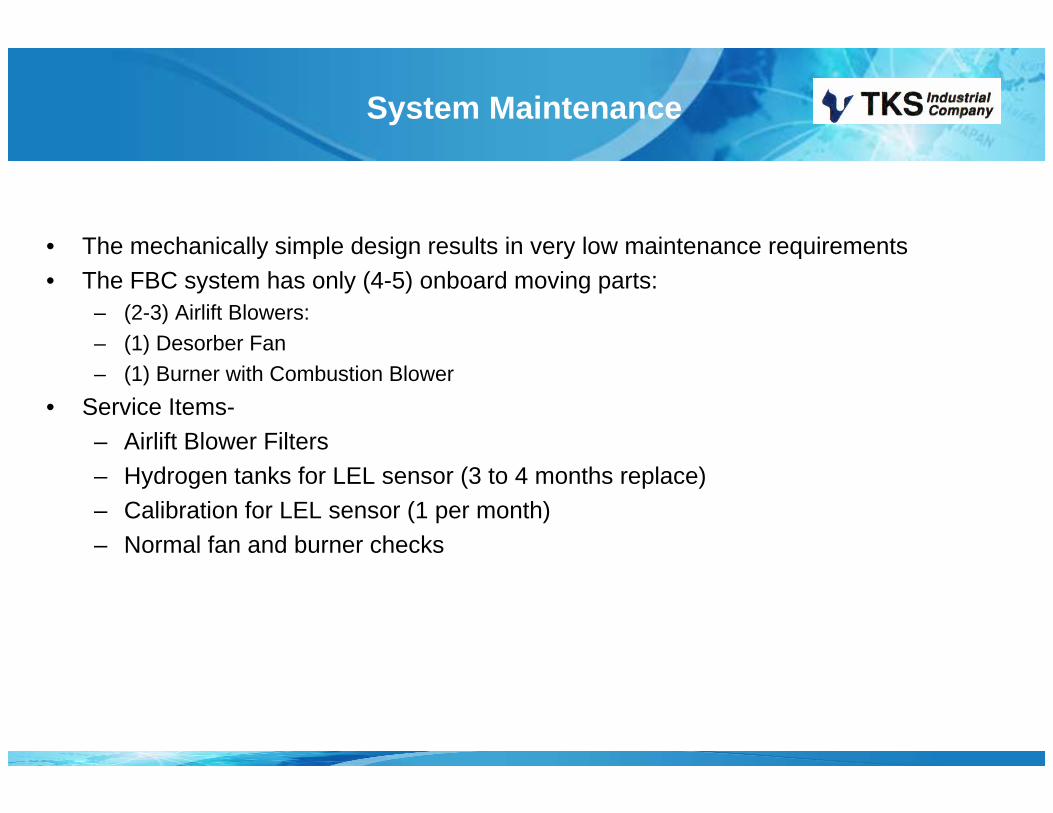
System Maintenance
• The mechanically simple design results in very low maintenance requirementsThe mechanically simple design results in very low maintenance requirements• The FBC system has only (4-5) onboard moving parts:
– (2-3) Airlift Blowers: – (1) Desorber Fan– (1) Burner with Combustion Blower
• Service Items-– Airlift Blower Filters– Hydrogen tanks for LEL sensor (3 to 4 months replace)– Calibration for LEL sensor (1 per month)– Normal fan and burner checks
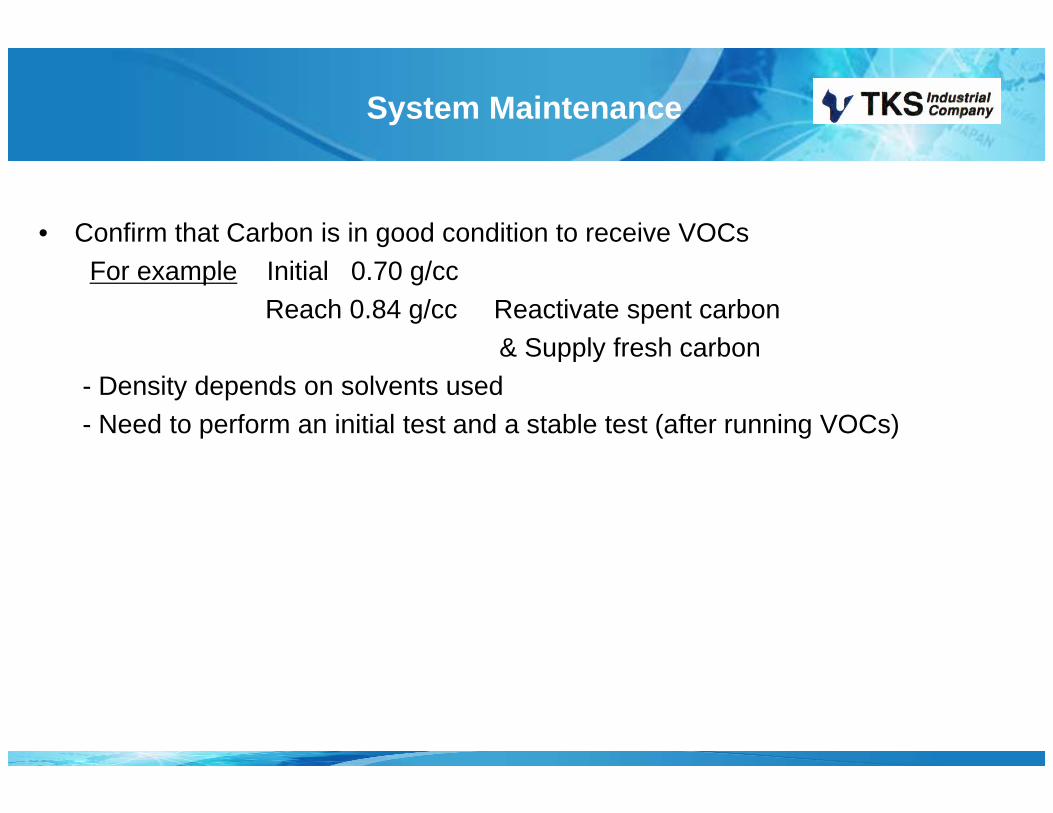
System Maintenance
• Confirm that Carbon is in good condition to receive VOCsFor example Initial 0.70 g/cc
Reach 0.84 g/cc Reactivate spent carbon& Supply fresh carbon& Supply fresh carbon
- Density depends on solvents used- Need to perform an initial test and a stable test (after running VOCs)
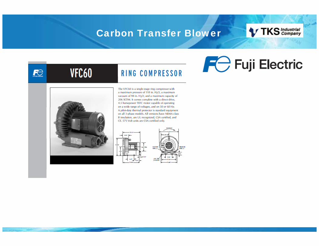
Carbon Transfer Blower
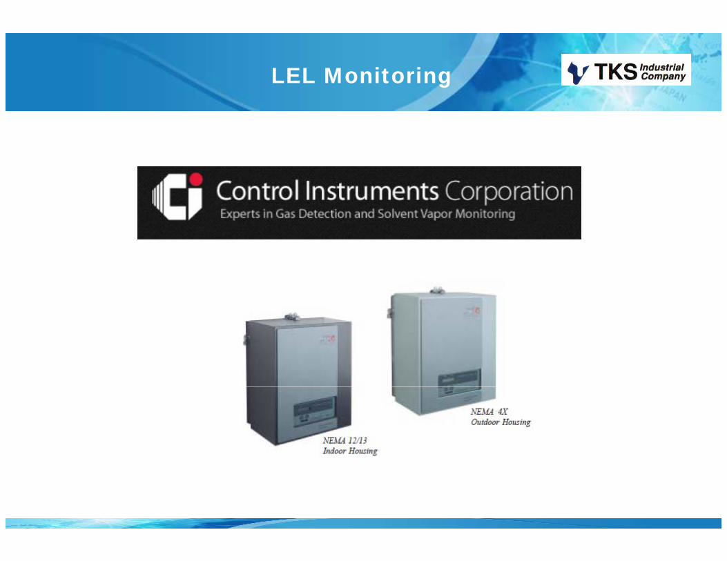
LEL Monitoring
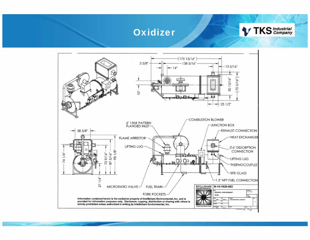
Oxidizer

Chart Recorder
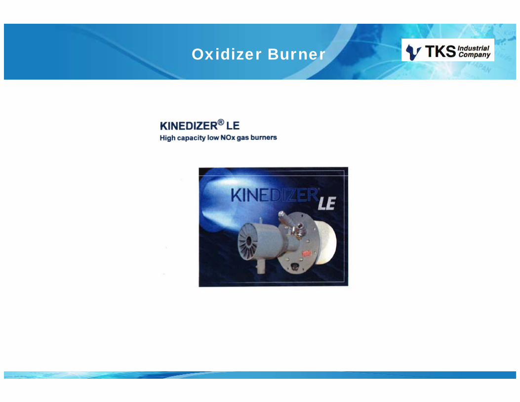
Oxidizer Burner

Gas Meter
Information needed For Proposal
• Air Volume to be Abated (CFM or M3/hr)• Air Volume to be Abated (CFM or M3/hr).• Solvent levels at highest volume booth spraying (lbs/hr or
g/hr).• Solvent list from Paints.• General specifications.• Location• Location• Required Destruction Efficiency (%).• Required other pollutant requirements (NOX, CO, CO2) - if
applicable.• Available installation area.
Th kThank you