Embed Size (px)
Citation preview
PERPUSTAKAAN UMP
LED STREET LI Jill 111111111111111111 )TIVE AUTO BEAM 0000071311
NURUL FADZLINA BINTI JAMIN
This thesis is submitted as partial fulfillment of the requirements for the award of
the Bachelor of Electrical Engineering (Electronics)
Faculty of Electrical & Electronics Engineering
Universiti Malaysia Pahang
JUNE 2012
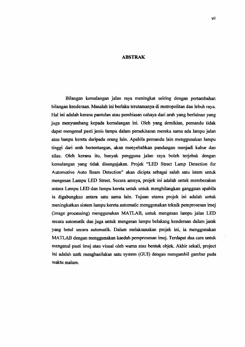
ABSTRACT
As vehicle population increases, the number of road accidents also increases.
Vital problems in transportation such as mobility and safety of transportation
considered more, especially in metropolitans and highway. It is because of the
reflection or refraction of light from different directions also contributed to this
accident. Due from that, the driver could not identify the types of lamps in their
environment whether it is street lamp or car lamp from others. When other drivers
use the high beam from the opposite direction, will cause the view is blurred and
glare. Due to that, many road users can be stuck with unintentional accident. The
project of Light Emitter Diode (LED) Street Lamp Detection for Automotive Auto
Beam Detection will be developed as addition features of the system to detect LED
Street Lamp. Basically, this project is to differentiate between LED Street Lamp and
car lamp to ignore LED noise when it is combined each other. The main purpose of
this project is to enhance the automated high beam detection system using image
processing technique in MATLAB, to detect LED street lamp for automated high
beam detection and also to detect the vehicle-rear lamp within its proper distance for
automated high beam detection. In order to implement this project, it was conducted
with computer simulation (MATLAB) by using image processing method. There are
two ways to identify the image or visual by its color or shape of the objects. My
expected outcome is to develop the Graphical Using Interface (GUI) by taking the
night vision images.
A
ABSTRAK
Bilangan kemalangan jalan raya meningkat seiring dengan pertambahan
bilangan kenderaan. Masalah ml berlaku terutamanya di metropolitan dan lebuh raya.
Hal mi adalah kerana pantulan atau pembiasan cahaya dari arah yang berlainan yang
juga menyumbang kepada kemalangan mi. Oleh yang demikian, pemandu tidak
dapat mengenal pasti jenis lampu dalam persekitaran mereka sama ada lampu jalan
atau lampu kereta danipada orang lain. Apabila pemandu lain menggunakan lampu
tinggi dari arah bertentangan, akan menyebabkan pandangan menjadi kabur dan
silau. Oleh kerana itu, banyak pengguna jalan raya boleh terjebak dengan
kemalangan yang tidak disengajakan. Projek "LED Street Lamp Detection for
Automotive Auto Beam Detection" akan dicipta sebagai salah satu istem untuk
mengesan Lampu LED Street. Secara amnya, projek mi adalah untuk membezakan
antara Lampu LED dan lampu kereta untuk untuk menghilangkan gangguan apabila
ia digabungkan antara satu sama lain. Tujuan utama projek mi adalah untuk
meningkatkan sistem lampu kereta automatic menggunakan teknik pemprosesan imej
(image processing) menggunakan MATLAB, untuk mengesan lampu jalan LED
secara automatik dan juga untuk mengesan lampu belakang kenderaan dalam jarak
yang betul secara automatik. Dalam melaksanakan projek ini, ia menggunakan
MATLAB dengan menggunakan kaedah pemprosesan imej. Terdapat dua cam untuk
mengenal pasti imej atau visual oleh warna atau bentuk objek. Akhir sekali, project
mi adalah untk menghasilakan saW system (GUI) dengan mengambil gambar path
waktu malam.
VII
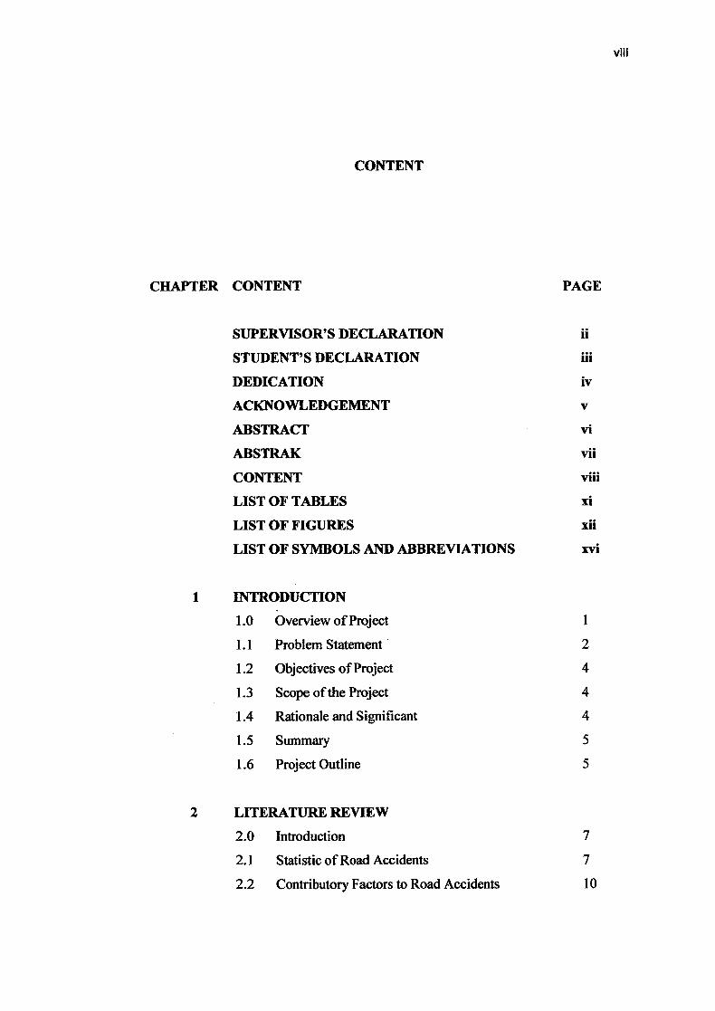
CONTENT
CHAPTER CONTENT PAGE
SUPERVISOR'S DECLARATION ii
STUDENT'S DECLARATION iii
DEDICATION iv
ACKNOWLEDGEMENT v
ABSTRACT vi
ABSTRAK vii
CONTENT viii
LIST OF TABLES xi
LIST OF FIGURES xii
LIST OF SYMBOLS AND ABBREVIATIONS xvi
INTRODUCTION
1.0 Overview of Project 1
1.1 Problem Statement 2
1.2 Objectives of Project 4
1.3 Scope of the Project 4
1.4 Rationale and Significant 4
1.5 Summary 5
1.6 Project Outline 5
2 LITERATURE REVIEW
2.0 Introduction 7
2.1 Statistic of Road Accidents 7
2.2 Contributory Factors to Road Accidents 10
VIII
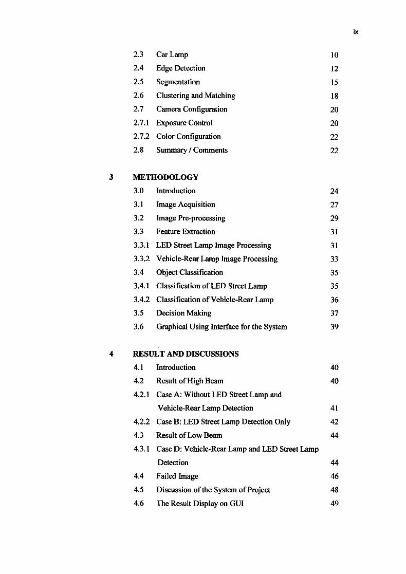
2.3 Car Lamp 10
2.4 Edge Detection 12
2.5 Segmentation 15
2.6 Clustering and Matching 18
2.7 Camera Configuration 20
2.7.1 Exposure Control 20
2.7.2 Color Configuration 22
2.8 Summary / Comments 22
3 METHODOLOGY
3.0 Introduction 24
3.1 Image Acquisition 27
3.2 Image Pre-processing 29
3.3 Feature Extraction 31
3.3.1 LED Street Lamp Image Processing 31
3.3.2 Vehicle-Rear Lamp Image Processing 33
3.4 Object Classification 35
3.4.1 Classification of LED Street Lamp 35
3.4.2 Classification of Vehicle-Rear Lamp 36
3.5 Decision Making 37
3.6 Graphical Using Interface for the System 39
4 RESULT AND DISCUSSIONS
4.1 Introduction 40
4.2 Result of High Beam 40
4.2.1 Case A: Without LED Street Lamp and
Vehicle-Rear Lamp Detection 41
4.2.2 Case B: LED Street Lamp Detection Only 42
4.3 Result of Low Beam 44
4.3.1 Case D: Vehicle-Rear Lamp and LED Street Lamp
Detection 44
4.4 Failed Image 46
4.5 Discussion of the System of Project 48
4.6 The Result Display on GUT 49
ix

CONCLUSION AND RECOMMENDATIONS
5.1 Introduction 50
5.2 Limitation 50
5.3 Recommendation 51
5.4 Conclusion 51
REFERENCES 52
A
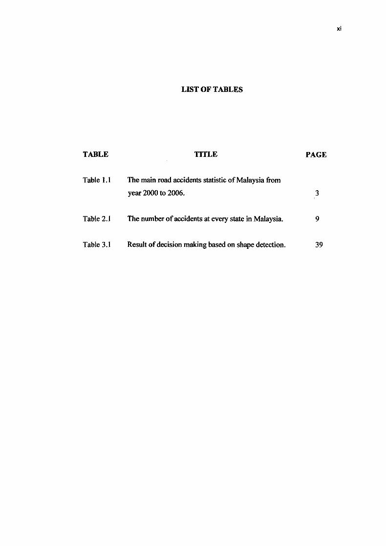
LIST OF TABLES
TABLE TITLE PAGE
Table 1.1 The main road accidents statistic of Malaysia from
year 2000 to 2006. 3
Table 2.1 The number of accidents at every state in Malaysia. 9
Table 3.1 Result of decision making based on shape detection. 39
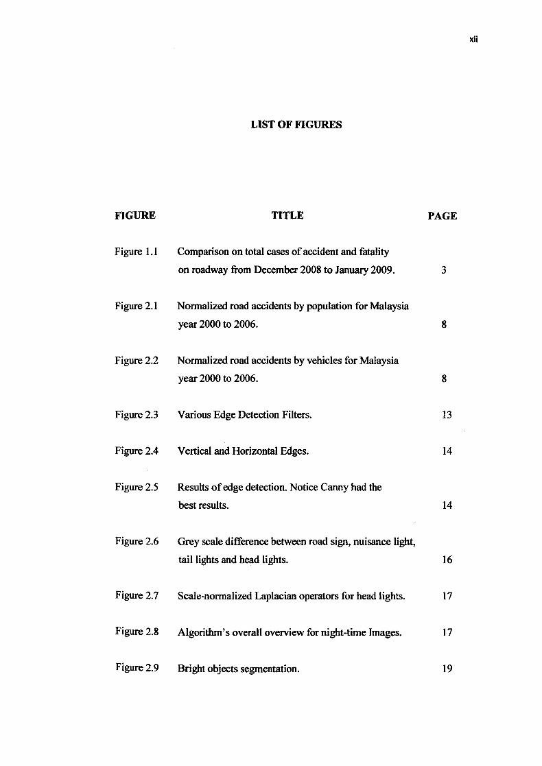
LIST OF FIGURES
FIGURE TITLE PAGE
Figure 1.1 Comparison on total cases of accident and fatality
on roadway from December 2008 to January 2009. 3
Figure 2.1 Normalized road accidents by population for Malaysia
year 2000 to 2006. 8
Figure 2.2 Normalized road accidents by vehicles for Malaysia
year 2000 to 2006. 8
Figure 2.3 Various Edge Detection Filters. 13
Figure 2.4 Vertical and Horizontal Edges. 14
Figure 2.5 Results of edge detection. Notice Canny had the
best results. 14
Figure 2.6 Grey scale difference between road sign, nuisance light,
tail lights and head lights. 16
Figure 2.7 Scale-normalized Laplacian operators for head lights. 17
Figure 2.8 Algorithm's overall overview for night-time Images. 17
Figure 2.9 Bright objects segmentation. 19
xii
Figure 2. 10 Vertical and horizontal projections. 19
Figure 2.11 Video frame captured with the automatic exposure control
enabled and Video frame captured using a lower static
exposure value. 21
Figure 3.1 General flow chart for overall system of Image Processing. 25
Figure 3.2 Flow chart for overall system of the Projec. t 25
Figure 3.3 Flow chart of the process. 26
Figure 3.4 Example of vehicle-rear lamp. 27
Figure 3.5 Example of combination LED street lamp and
vehicle-rear lamp. 28
Figure 3.6 Example of LED street lamp without vehicle. 28
Figure 3.7 Original RGB image. 29
Figure 3.8 Original image converted to level J4SV. 30
Figure 3.9 Original image converted to level gray-scale. 30
Figure 3.10 Only some area of image converted to RGB. 31
Figure 3.11 The spatial filtering process using Gaussian. 32
Figure 3.12 Binary image for LED street lamp process. 32
Figure 3.13 Remove the noise especially near to the LED street lamp. 33
Figure 3.14 Binary image for vehicle-rear lamp process. 34
XIII
xiv
Figure 3.15 The gap was filled to make it clear. 34
Figure 3.16 LED street lamp detection in yellow mark. 36
Figure 3.17 Vehicle-rear lamp detection in blue mark. 37
Figure 3.18 The result of LED street lamp and vehicle-rear lamp
Detection. 38
Figure 3.19 The result of the decision making for Low Beam. 38
Figure 320 The Graphical Using Interface (GUI) for the system 39
Figure 4.1 The result of without any detection of LED street lamp
and vehicle-rear lamp (Use High Beam). 41
Figure 4.2 High Beam for result of without LED street lamp and
vehicle-rear lamp detection display in Command Window. 42
Figure 4.3 The result of LED street detection (Use High Beam). 43
Figure 4.4 High Beam for result of LED street lamp detection
display in Command Window. 43
Figure 4.5 The result of LED street lamp and vehicle-rear lamp
detection (Use Low Beam). 45
Figure 4.6 Low Beam for result of LED street lamp and
vehicle-rear lamp detection display in Command Window. 45
Figure 4.7 The system was failed to detect the vehicle-rear lamp. 46
Figure 4.8 The system was failed to detect the LED street lamp and
vehicle-rear lamp. 47
xv
Figure 4.9 The system was failed to detect vehicle-rear lamp. 48
Figure 4.10 The interface of LED street lamp and vehicle-rear
lamp detection 49
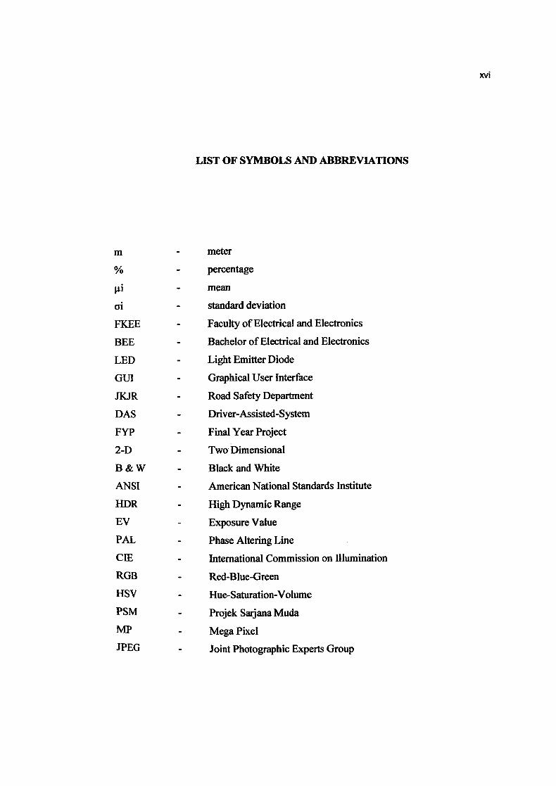
LIST OF SYMBOLS AND ABBREVIATIONS
m - meter
% - percentage
- mean
ci - standard deviation
FKEE - Faculty of Electrical and Electronics
BEE - Bachelor of Electrical and Electronics
LED - Light Emitter Diode
GUI - Graphical User Interface
JKJR - Road Safety Department
DAS - Driver-Assisted-System
FYP - Final Year Project
2-1) - Two Dimensional
B & W - Black and White
ANSI - American National Standards Institute
HDR - High Dynamic Range
EV - Exposure Value
PAL - Phase Altering Line
CIE - International Commission on illumination
RGB - Red-Blue-Green
HSV - Hue-Saturation-Volume
PSM - Projek Sarjana Muda
MP - Mega Pixel
JPEG - Joint Photographic Experts Group
MA
CHAPTER 1
INTRODUCTION
1.0 Overview of Project
Vehicles such as transport cars, buses, trucks and motorcycles are among the
indispensable transportation in Malaysia to carry people and things from one destination
to another using the road as a medium of instruction. Therefore, the automatic vehicle
letection is a very important aspect in the road transportation system.
Although there is usually less traffic at night, it is common that accidents
Dccurred at night. Some of the reasons for night road accidents are that most drivers are
limited in night vision since some roads can be very dark with the absence of road
lamps. Hence, the driver will always use the high beam to help them have a better vision
luring driving on the road without realizing the behavior of the potential indirect hazard
for others. Hence, there is a need to have a system that can control the beam's mode to
help reduce driver's alertness to beam's mode changes.
Image analysis provides a number of effective techniques to enable it to detect
the target object in the image and it is widely used in traffic monitoring system.
1
2
Basically, the present invention detects and was also classifies objects in a real-time, in a
series of images obtained from cameras mounted on vehicles. The objects that will be
detected by image analysis techniques are vehicle headlights, taillights leading vehicle,
street lamps and also car rear lights for the car driving in front.
The auto beam control system, is developed by the classification of objects
created using image analysis is intended to alert the changes from high beam to low
beam or otherwise. Apart from that, the use of high beam is one of visual disturbances
and may create a safety hazard by making oncoming vision is blurred and glare.
It is a common thing in the way of road at night when the driver forgot to turn on
or off the beam when confronted with an incoming vehicle. This research will facilitate
in the automation of head lamp's change using a camera that detects the Street lamps,
incoming car lamps and rear lights.
1.1 Problem Statement
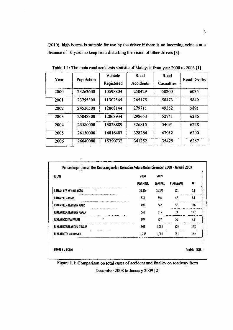
As shown in Table 1.1 and Figure 1. 1, it can be seen that the number of accidents
increase every year and these accidents include those that happened at night. The
darkness and the glare of vision is a major factor contributing to this accident. This is
because, the driver normally is confused between the road lights and car lights coming
from the opposite direction.
This will make the driver negligent and forgot to change the high beams to the
low beams. Indirectly, it leads to serious consequences to the driver coming from the Opp
osite direction and the cars in front that are in the same direction because the in
vision and will be glared. This is because, according to a study conducted by Marizuana
3
(2010), high beams is suitable for use by the driver if there is no incoming vehicle at a
distance of 10 yards to keep from disturbing the vision of other drivers [3].
Table 1.1: The main road accidents statistic of Malaysia from year 2000 to 2006 [1]
Year PopulationVehicle
Registered
Road
Accidents
Road
CasualtiesRoad Deaths
2000 23263600 10598804 250429 50200 6035
- 2001 23795300 11302545 265175 50473 5849
2002 24526500 12068144 279711 49552 5891
2003 25048300 12868934 298653 52741 6286
2004 25580000 13828889 326815 54091 6228
2005 26130000 14816407 328264 47012 6200
2006 26640000 15790732 341252 35425 6287
Perbandinqanlumlah Kes Kemaangan dan Kemalian Antara Uulan Disember 2008 - Januari 2009
2009
JANUAJU PERBEZAAN %
31,277 121 OA J 598 47 8.5
542 52 10.6
615 74 13.7
77 - 7,_ I 1,085
--179 - - 19.8
1,386 151 12.2 1
BULAN
2008
DISEMBER
JUHLAH KES KENALANGAN
31,156
JUN[AH KEMATIAN
551
JLJXLAH KENMANGAN iiAur
490
JUMLAH KEMALANGAN PARAH
541
JUMLAHCEDERAPARAH
687
JUNLAH KEMALANGAN RINGAN
906
JLJMI.AH CEBERA RINGAN
1,235
SUNBER: PORN
Analisis:JK]R
Figure 1.1: Comparison on total cases of accident and fatality on roadway from
December 2008 to January 2009 [2]
4
1.2 Objectives of Project
The main purpose of the project as listed:
(i) To enhance the automated high beam detection system using image processing
technique in MATLAB.
(ii) To detect LED street lamp for automated high low beam detection.
(iii)To detect the vehicle-rear lamp for automated high low beam detection.
1.3 Scope of the Project
In order to achieve the objectives, the project is focus on image processing of the
LED street lamp and detect image of vehicle rear-lamp of high low beam for the
algorithm development. On the other hand, for the vehicle rear-lamp, a few assumptions
are made, such that speed of the car in front is the same with the speed of car at the back.
The systems will only functions at night and the project will be simulated and analyzed
using MATLAB.
1.4 Rationale and Significant
The impact of this project is to help the driver to have a good technique of
driving on the road environment. The project is intended to improve the efficiency and is
a part of Driver-Assisted-System (DAS) so that the driver can drive their vehicle with
more effective control.
5
The significant of this research is to study the possibility detection of LED street
lamp and car rear lights for the car driving in front in order to make the high and low
beam changing automatically for solvents road accidents especially in highway and
hence give an alternative how to reduce or decrease the number of accidents in
Malaysia. Besides that, this study will help to establish a suitable parameter (7 m to 10
m) to overcome the beam detection for the car rear lights for the car driving in front.
1.5 Summary
This section or chapter is all about an overall project and explains the objectives
as well as the scope of the project in order to give an insight and idea of the project. On
the other hand, this section also comes out with the problem statement and the
significant of the system. On the next chapter will discuss about the literature review on
the functions, principles and application on each component of this project.
1.6 Project Outline
This thesis comprise 5 chapters altogether. Chapter 1 is on introduction, Chapter
2 is literature review, Chapter 3 contains methodology, Chapter 4 is on result and
discussion followed by last chapter which is Chapter 5 is conclusion.
6
Chapter 1 is the section where the introduction of the thesis of project will be
discussed. The overview of the project will be outlined including problem statement, the
projects' objective and also the project scope.
Chapter 2 there will be discussing the literature review of previous works from
thesis, journals and experiments that related to the project. The review includes LED
street lamp, vehicle-rear lamp and the methods that they used to analyze the image.
Chapter 3 represents the research methodology of this project. The step by step
procedure use to run this project from the beginning till end will be explained in detail.
This will also include the procedures or flow chart and processes involved for the
software development of the entire project.
Chapter 4 was consists of the experimental results and its respective analysis.
The result obtained will be discussed and explained here with the aid of figures. The
comparison of the every case will be discussed here.
In Chapter 5, here would be the summarized of the thesis and further
recommendation for the research.
CHAPTER 2
LITERATURE REVIEW
2.0 Introduction
Several related researches have been done to develop the system in order to
detect street lamp and vehicle-rear lamp of this project. The references for this project
are taken from journals, conferences and also articles that was cited directly from
reliable internet sources regarding the lamps detection.
2.1 Statistic of Road Accidents
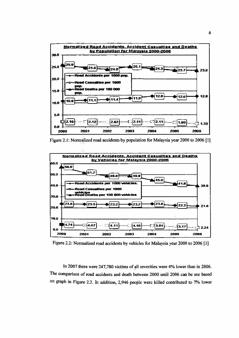
As shown in the graph of Figure 2. 1, it was stated the normalized road accidents,
accident casualties and deaths by population for Malaysia in six years from 2000 to
2006.
7
8
Normalted Road Accidents. Accident Casualties and Deaths by Population for Malaysia 2000-2006
30.0
25.0
1—s—Road *cc1dø.s per 1000 pep.
1 -u-Road Casualles per 1000 I pop. 1-. --Road Deaths per 100000
pep.
2001 2002 2003 2004 2005
Figure 2.1: Normalized road accidents by population for Malaysia year 2000 to 2006 [1]
Figure 2.2: Normalized road accidents by vehicles for Malaysia year 2000 to 2006 [1]
In 2007 there were 247,780 victims of all seventies were 4% lower than in 2006.
The comparison of road accidents and death between 2000 until 2006 can be see based
on graph in Figure 2.2. In addition, 2,946 people were killed contributed to 7% lower
15.0
100
5.0
0.0 2
r-23.7-. 23.6
12.8
I 1.33
9
than in 2006. 27,774 people were seriously injured in 2000 which decreased to 3% from
2006 and 217,060 injured persons were below the 4% compared to 2006. Accordingly,
the government published a road safety strategy that is called More Secured Tomorrow
than Today [4]. This strategy is made is to achieve:
(i) 40% reduction in the number of people killed or seriously injured.
(ii) 50% reduction in the number of children killed or seriously injured.
(iii)10% reduction in bit rate for the number of injured victims.
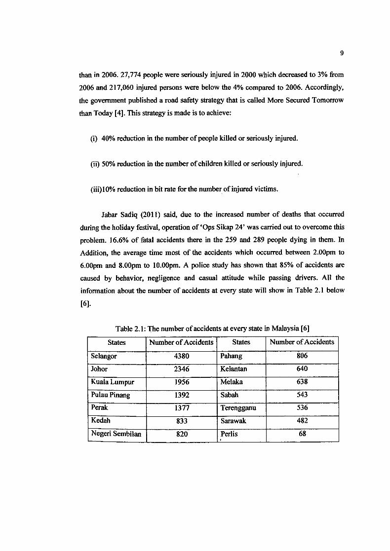
Jabar Sadiq (2011) said, due to the increased number of deaths that occurred
during the holiday festival, operation of 'Ops Sikap 24' was carried out to overcome this
problem. 16.6% of fatal accidents there in the 259 and 289 people dying in them. In
Addition, the average time most of the accidents which occurred between 2.00pm to
6.00pm and 8.00pm to 10.00pm. A police study has shown that 85% of accidents are
caused by behavior, negligence and casual attitude while passing drivers. All the
information about the number of accidents at every state will show in Table 2.1 below
[6].
Table 2.1: The number of accidents at every state in Malaysia [6]
States Number of Accidents States Number of Accidents
Selangor 4380 Pahang 806
Johor 2346 Kelantan 640
Kuala Lumpur 1956 Melaka 638
Pulau Pinang 1392 Sabah 543
Perak 1377 Terengganu 536
Kedah 833 Sarawak 482
Negeri Sembilan 820 Perlis 68
10
2.2 Contributory Factors to Road Accidents
The failure of drivers to see properly is the most frequent contributing factor was
reported in 35% of all accidents. It is because; the driver is difficult to see clearly the
environmental conditions of road. This includes lighting, glare, rain and foggy weather.
In addition, four of the five factors most frequently reported are caused by the drivers'
carelessness in driving on the road and lost control of vehicle driven. These factors
resulted in 33% of fatal accidents [4].
On the other hand, S.0 Donald Lim (2002) has a different opinion in New Straits
Times, where road accidents are caused by driver's behavior that fails to give proper
signal when turning. Some other bad behaviors are when driver are the use of mobile
phone while driving and smoking while driving. These are also a factor that contributed
to the accident [5].
Meanwhile, H.M Heeza (2011) appears and claimed in Bernama Newspaper to
support the opinion expressed by the New Straits Times claimed; the negligent driver
and bad road conditions are the main cause of the increasing number of road accidents in
the country. Director of Kuala Lumpur Road Safety Department (JKJR) stressed that
70% of road accidents are caused by human negligence, 20% due to road conditions and
10% for vehicle problems [7].
2.3 Car Lamp
Marjzuana (2010) claimed in her Final Year Project (FYP) thesis, basically the
car lights are a member who holds a number of other lights in the shape of the loop.

11
Members who hold the light and hold the hole in the vicinity of each hole holding the
lamp. Some passages of light to communicate with every corner of the hold. Light
sources will be protected behind those passages of light, respectively. Each of the
members of the ring-shaped light thereon equidistantly spaced bumps condensed light,
and installed in one corner of their holdings to the parent. Therefore, the light source
changes are allowed, and the light in the shape of the closed-loop will run at all members
of the ring-shaped light when powered light source [3].
Moll and Gregory R (2004) claimed, the vehicle lighting systems consisting of
several parts of the mounting base has an elongated body and the body has a central
portion with a central bearing surface to contact the mounting surface. Parts of the body
including a pair of flanges having upwardly depending portion extends from the center
and downwardly depending on the parts that form a bearing surface spaced from the
central bearing surface for contacting the mounting surface. The center has opposed
longitudinal grooves of said bearing surface and the center of the longitudinal grooves
extending along said base. Longitudinal grooves and the inner surface of said flange and
defining the former elongated flexible strip light and kept in position by the flange of the
container. Significant band of light contained in the container, where bands of light
consist of a transparent polymer material body and the diversity of light sources
contained within the polymer body. In addition, the band of light with electrical contacts
for coupling light into the power supply source [8].
Moll and Gregory R (2004) also said, the vehicle lighting systems consisting of a
base having a longitudinal body, which has a longitudinal groove and against the distal
end. Each groove against the distal end with a pair of recessed mounting axis extending
into the distal end and extending generally parallel to the longitudinal grooves. Flexible
strip light beam position and stored by the band of light that is found in the longitudinal
grooves. At least one end cap coupled to the base of the distal end. End cap has a
shoulder abutting the distal end of the distal send of the base shoulder and projections,
including projections of axially extending up to the mounting recess for coupling to the
distal end of the base [8].
12
2.4 Edge Detection
Claypoole R, Lewis J, Bhashyarn, and Kelly (2009) entitlement, the most
effective way to do edge detection is divided into two categories; there are the gradient
and laplacian. Where the gradient method is detect edges by find the first derivative of
maximum and minimum image. Whereas, the laplacian method is to do a detection of
edges by find zero crossing in the second derivative image. The Figure 2.3 shows the
edge detected image using the gradient method (Roberts, Prewit, Sobel) and laplacian
method (Marrs-Hildreth) [9].
Claypoole R, Lewis J, Bhashyam, and Kelly (2009) also said, the Marr-Hildreth
not only has a lot more noise than the other methods, the low-pass filtering it uses
distorts the actual position of the facial features. Due to the nature of the Sobel and
Prewitt filters we can select out only vertical and horizontal edges of the image as shown
on Figure 2.4 below. This is very useful since we do not want to morph a vertical edge
in the initial image to a horizontal edge in the final image. This would cause a lot of
warping in the transition image and thus a bad morph [9].
On the other side, Jason Nearing, Rob Pickel and Anil Maliyekkel (2009) were
give their explanation' about the first step to segmenting images into regions is to
determine where the edges are. The several different edge-detection filters including true
sobel, true prewitt, Laplacian of Gaussian, and a mix of sobel and prewitt had been tried.
Due to that, one of the sources which are combination of sobel and prewitt could provide
a more optimal detection scheme. This 3x3 did in fact seem to work better than either
one of them alone. Another attempt was to use a Laplacian edge detector, but it picked
up so much noise that it was nearly impossible to determine any regions. Also, the
Laplacian filter did give thin edges, yet some were so thin that when tried filling in the
enclosed regions, many of the regions ended up bleeding together [10].