Embed Size (px)
Citation preview
Application Note Manufacturing Output Seite 1 von 22
Title: Manufacturing Output Product: OrCAD / Allegro PCB Editor Summary: Detailed information about Gerber, NC Drill
and NC Route. Author/Date: Beate Wilke / 27.05.2009
Table of Contents
1 Gerber............................................................................................................................ 2
1.1 Setup Artwork ........................................................................................................ 2 2 NC Drill........................................................................................................................... 4
2.1 Setup NC Drill ........................................................................................................ 4 2.2 Drill Customization ................................................................................................. 4 2.3 Auto Generation of Symbols .................................................................................. 6 2.4 Library Drill Report ................................................................................................. 7 2.5 Setup Drill Legend ................................................................................................. 7 2.6 The Drill Legend Menu........................................................................................... 8 2.7 Drill Template File Fields.......................................................................................14 2.8 Customizing Drill Template Files...........................................................................18
3 NC Route ......................................................................................................................21 3.1 Guidelines.............................................................................................................21 3.2 Defining the Cutting Path ......................................................................................21 3.3 Using the ncroutebits.txt text file ...........................................................................22
Application Note Manufacturing Output Seite 2 von 22
1 Gerber
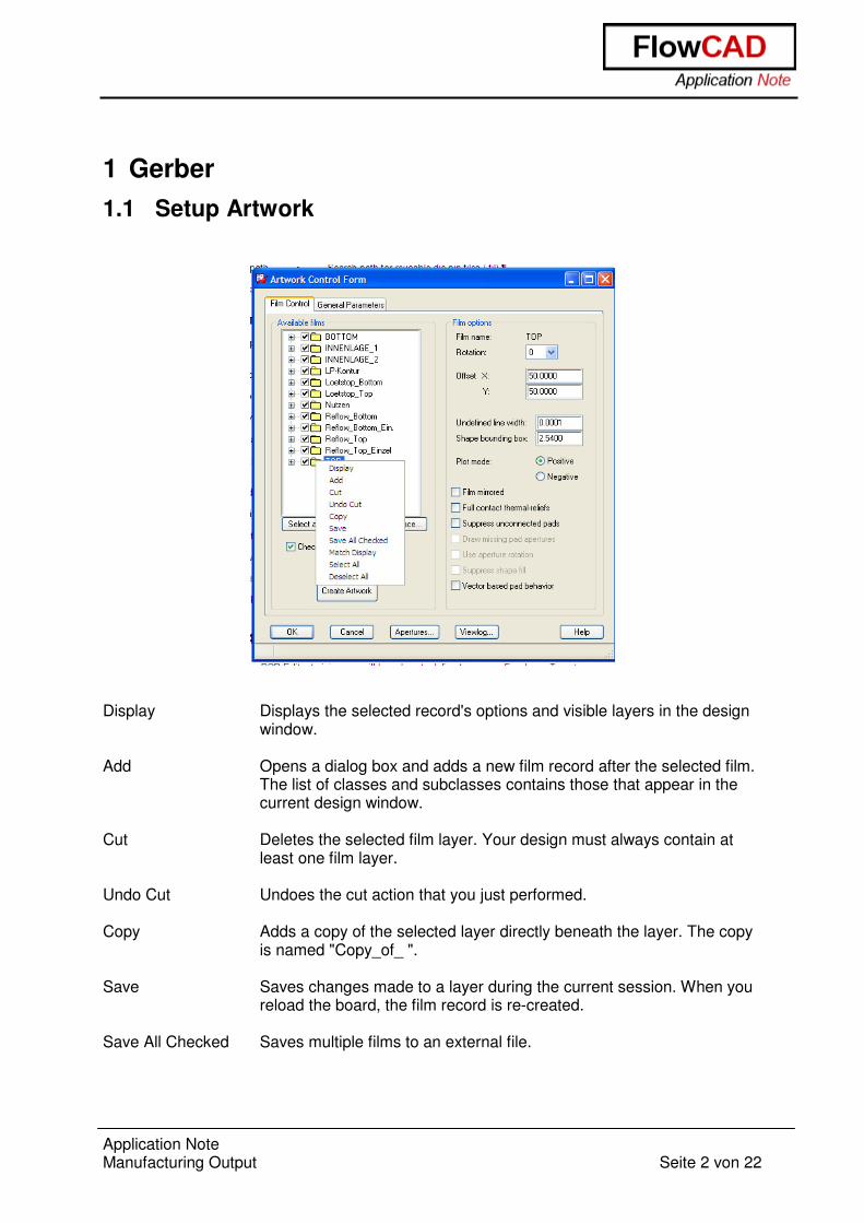
1.1 Setup Artwork
Display Displays the selected record's options and visible layers in the design
window. Add Opens a dialog box and adds a new film record after the selected film.
The list of classes and subclasses contains those that appear in the current design window.
Cut Deletes the selected film layer. Your design must always contain at
least one film layer. Undo Cut Undoes the cut action that you just performed. Copy Adds a copy of the selected layer directly beneath the layer. The copy
is named "Copy_of_ ". Save Saves changes made to a layer during the current session. When you
reload the board, the film record is re-created. Save All Checked Saves multiple films to an external file.
Application Note Manufacturing Output Seite 3 von 22
Match Display Deletes all class and subclass items from the film and replaces them with the list of classes and subclasses that appear in the current window.
Select All Lets you choose all the available films. Deselect All Deselects the films you have chosen.
With Add and Replace you can add or replace film settings from a text file which you created with Save All Checked. Example for a film_setup.txt file:
Application Note Manufacturing Output Seite 4 von 22
2 NC Drill
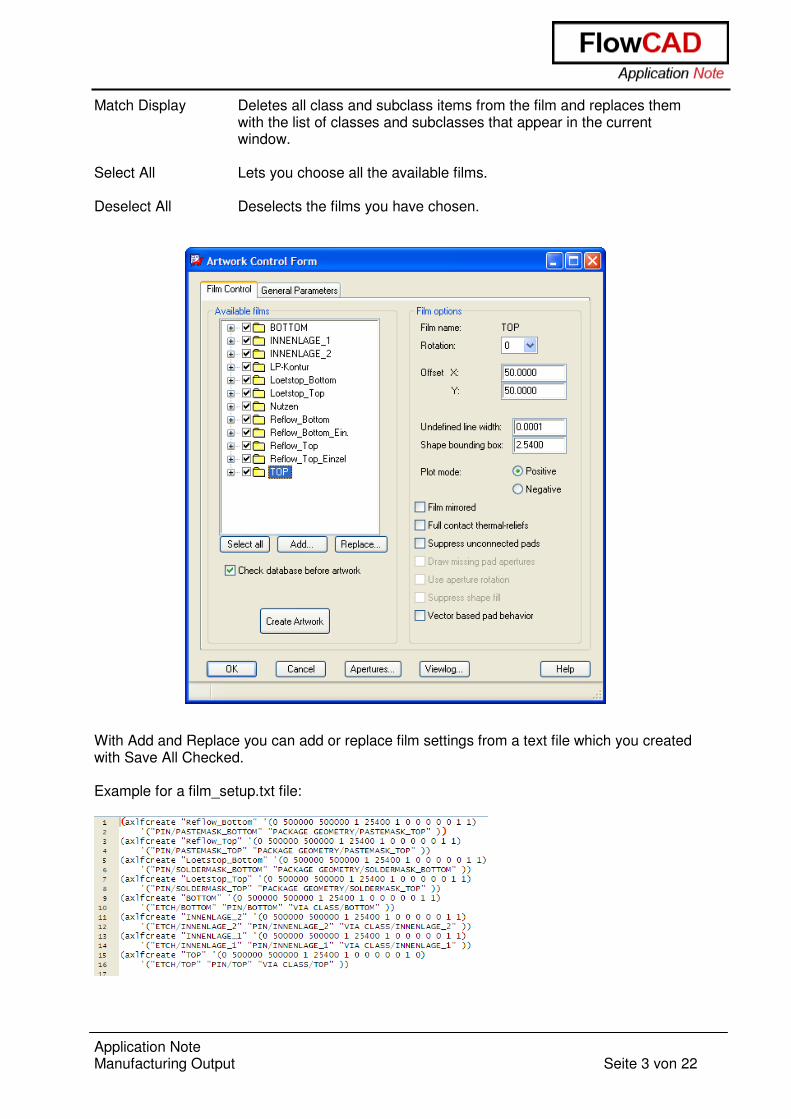
2.1 Setup NC Drill
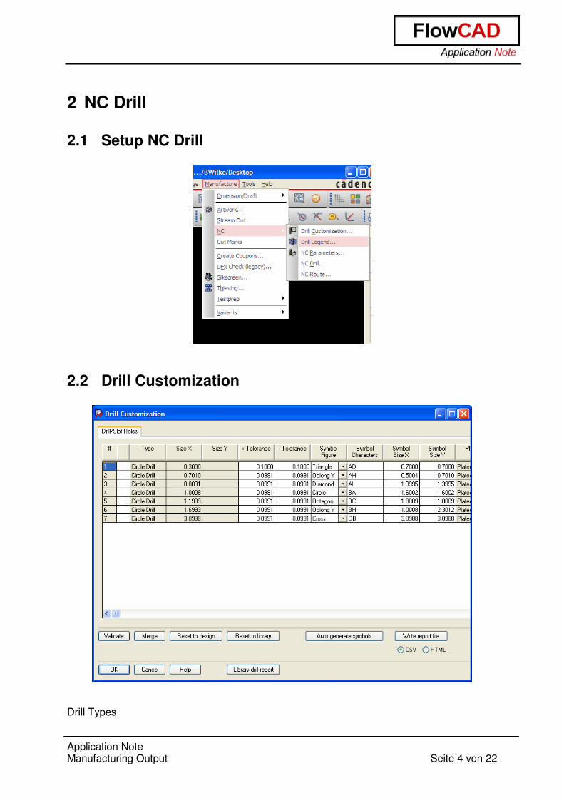
2.2 Drill Customization
Drill Types

Application Note Manufacturing Output Seite 5 von 22
The number of rows within the spreadsheet aligns with the number of unique padstack definitions containing a drill in the database. The holes are divided up into eight sections and sorted by ascending X size within their section. Editing and Overrides Any override within the spreadsheet appears in blue. Edit a single cell or change an entire column by placing the cursor over a specific cell, then right clicking and choosing Set All. To reset the values back to the original design state or values as represented by the library symbol, use Reset to Design or Reset to Library. Validation The validate function scans the list of padstacks and flags those with identical definitions. Two conditions are possible, and the second column of the spreadsheet graphically represents them as red or yellow. - Red: Two different holes have identical definitions. - Yellow: The same hole is represented more than one time in the spreadsheet and has the
same definition. This is an opportunity to merge the rows. In the example below, the 10- and 12-mil drills have the same Figure, Character, and Symbol sizes Both rows are flagged with red; the number 1 embedded in the red cell references the row of the first drill containing this error. To resolve the issue, change a value in any of the Figure, Character, or Symbol size cells. The yellow condition flags the two 55-mil drills having the same Figure, Character, and Symbol sizes. Use the Merge button to combine these rows into a single entry.
Application Note Manufacturing Output Seite 6 von 22
2.3 Auto Generation of Symbols An automatic symbol-generation utility creates design specific symbols based on an internal algorithm. The current drill figures supported by Allegro will be used in the following order for up to and including the first eleven drill holes. Users cannot influence the sorting of this list. - Cross (typical for the smallest/highest quantity) - Square - Hexagon X - Hexagon Y - Octagon - Diamond - Triangle - Oblong X - Oblong Y - Rectangle - Circle
For holes beyond eleven, drill characters rather than drill figures are used in the order A-Z, AA, AB … AZ, BA, BB … BZ, etc. Any slot holes use the characters OA … OZ, and if necessary, PA … PZ and QA … QZ, for oval slots, and characters RA … RZ, SA … SZ, etc. for rectangle slots. For circular drill holes, the Symbol Size in both X and Y will be automatically set to the size of the hole itself. For slot holes Symbol Size X and Y will not be altered by automatic symbol generation and remain fixed at the size of the slot hole itself.
Application Note Manufacturing Output Seite 7 von 22
2.4 Library Drill Report
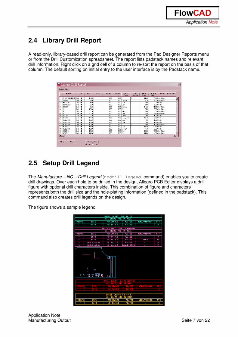
A read-only, library-based drill report can be generated from the Pad Designer Reports menu or from the Drill Customization spreadsheet. The report lists padstack names and relevant drill information. Right click on a grid cell of a column to re-sort the report on the basis of that column. The default sorting on initial entry to the user interface is by the Padstack name.
2.5 Setup Drill Legend
The Manufacture – NC – Drill Legend (ncdrill legend command) enables you to create drill drawings. Over each hole to be drilled in the design, Allegro PCB Editor displays a drill figure with optional drill characters inside. This combination of figure and characters represents both the drill size and the hole-plating information (defined in the padstack). This command also creates drill legends on the design. The figure shows a sample legend.
Application Note Manufacturing Output Seite 8 von 22
2.6 The Drill Legend Menu
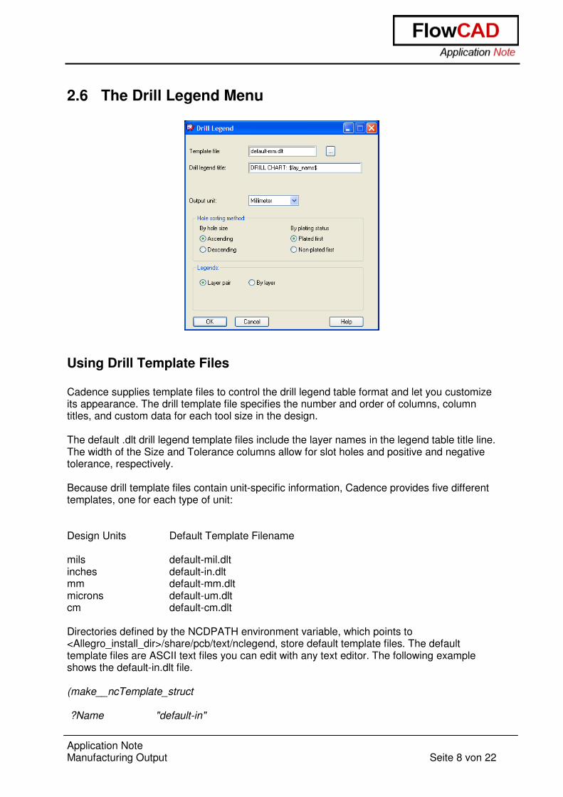
Using Drill Template Files Cadence supplies template files to control the drill legend table format and let you customize its appearance. The drill template file specifies the number and order of columns, column titles, and custom data for each tool size in the design. The default .dlt drill legend template files include the layer names in the legend table title line. The width of the Size and Tolerance columns allow for slot holes and positive and negative tolerance, respectively. Because drill template files contain unit-specific information, Cadence provides five different templates, one for each type of unit: Design Units Default Template Filename mils default-mil.dlt inches default-in.dlt mm default-mm.dlt microns default-um.dlt cm default-cm.dlt Directories defined by the NCDPATH environment variable, which points to <Allegro_install_dir>/share/pcb/text/nclegend, store default template files. The default template files are ASCII text files you can edit with any text editor. The following example shows the default-in.dlt file. (make__ncTemplate_struct ?Name "default-in"
Application Note Manufacturing Output Seite 9 von 22
?Units "inches" ; ; ?TitleHeight ; ------------ ; ; Height of the main title line row in units as indicated by ?Units. ; This height must take into account a title that may in fact be multi-line. ; ?TitleHeight 0.25 ; ; Text block id numbers to be used for the actual title text, the column header ; text, and text appearing in each drill data row, respectively. ; ?TitleTextBlock 9 ?ColumnTitleTextBlock 9 ?DataTextBlock 9 ; ; Order of holes in the legend table based on plating status. ; ; "PlatedFirst" or "NonPlatedFirst" ; ?PlatingOrder "PlatedFirst" ; ; ?Title ; ------ ; ; ?Title Title for 'Layer pair' drill legends, and default title ; for other drill legend types when not specified otherwise. ; ; ?TitleByLayer Title for 'By layer' drill legends. ; ; ?TitleBackdrill Title for 'Backdrill' drill legends. ; ; The appearance of the string "$lay_nams$" indicates where "<layer name> to <layer name>" ; may appear in a title, while "$lay_nums$" indicates where "<layer number> to <layer number>" ; may appear in a title. ; ; The appearance of '|' characters in the title string will cause subsequent text ; in the title to start on a new line. It is up to the user to change the ?TitleHeight ; specification accordingly, as it will not automatically be changed. ; ?Title "DRILL CHART: $lay_nams$" ?TitleByLayer "BY LAYER: $lay_nams$" ?TitleBackdrill "BACKDRILL: $lay_nams$" ; ; ?UnitsTitle ; ----------- ; ; The units title line appearing in the 2nd header row. ; The appearance of the string "$units_id$" in the title line indicates ; where the actual units identifier is to be located in the string.
Application Note Manufacturing Output Seite 10 von 22
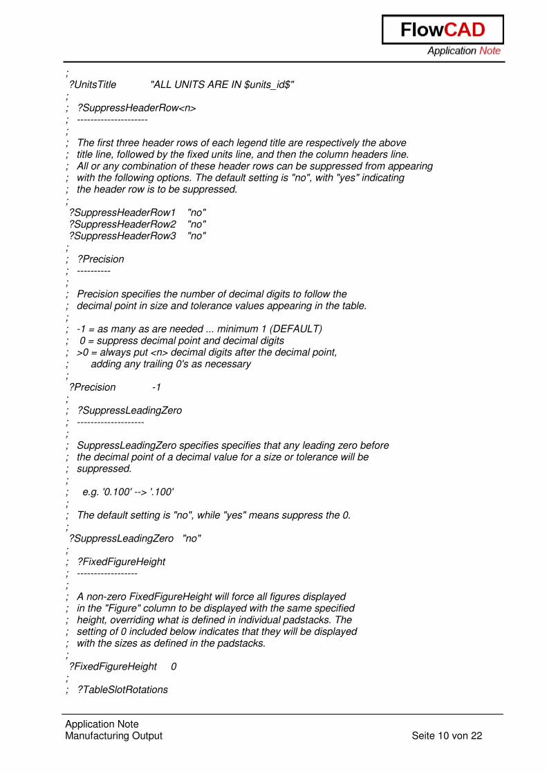
; ?UnitsTitle "ALL UNITS ARE IN $units_id$" ; ; ?SuppressHeaderRow<n> ; --------------------- ; ; The first three header rows of each legend title are respectively the above ; title line, followed by the fixed units line, and then the column headers line. ; All or any combination of these header rows can be suppressed from appearing ; with the following options. The default setting is "no", with "yes" indicating ; the header row is to be suppressed. ; ?SuppressHeaderRow1 "no" ?SuppressHeaderRow2 "no" ?SuppressHeaderRow3 "no" ; ; ?Precision ; ---------- ; ; Precision specifies the number of decimal digits to follow the ; decimal point in size and tolerance values appearing in the table. ; ; -1 = as many as are needed ... minimum 1 (DEFAULT) ; 0 = suppress decimal point and decimal digits ; >0 = always put <n> decimal digits after the decimal point, ; adding any trailing 0's as necessary ; ?Precision -1 ; ; ?SuppressLeadingZero ; -------------------- ; ; SuppressLeadingZero specifies specifies that any leading zero before ; the decimal point of a decimal value for a size or tolerance will be ; suppressed. ; ; e.g. '0.100' --> '.100' ; ; The default setting is "no", while "yes" means suppress the 0. ; ?SuppressLeadingZero "no" ; ; ?FixedFigureHeight ; ------------------ ; ; A non-zero FixedFigureHeight will force all figures displayed ; in the "Figure" column to be displayed with the same specified ; height, overriding what is defined in individual padstacks. The ; setting of 0 included below indicates that they will be displayed ; with the sizes as defined in the padstacks. ; ?FixedFigureHeight 0 ; ; ?TableSlotRotations
Application Note Manufacturing Output Seite 11 von 22
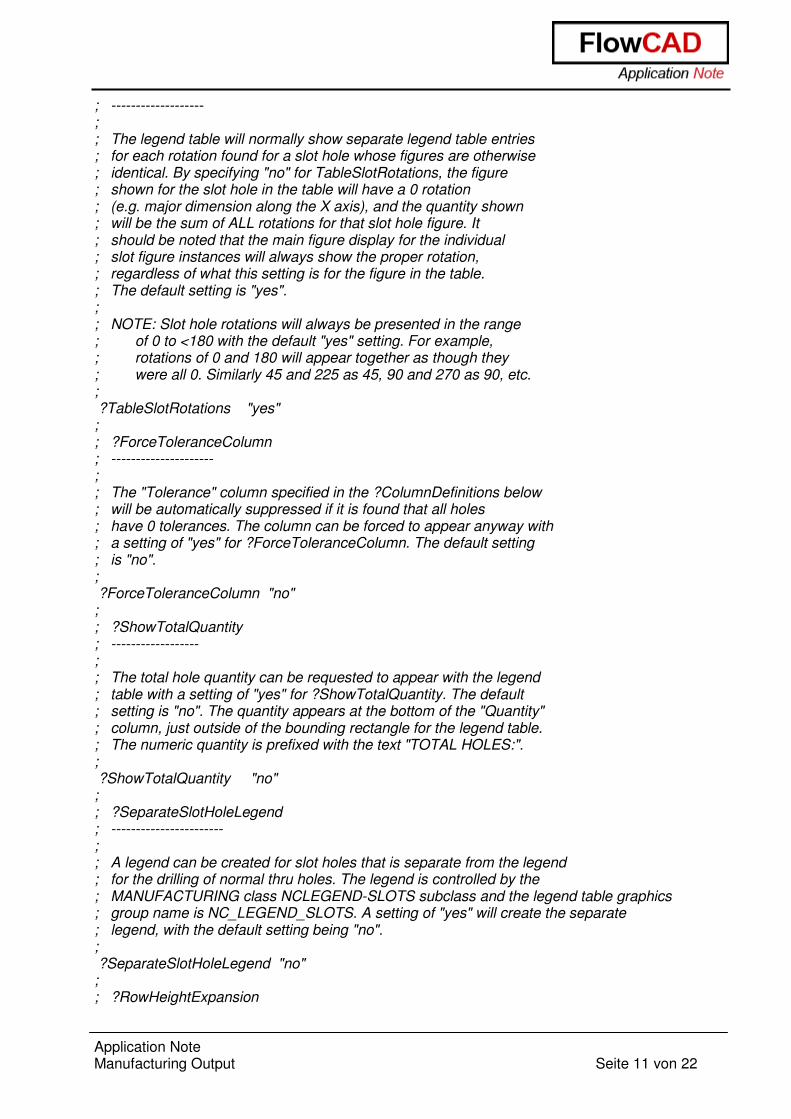
; ------------------- ; ; The legend table will normally show separate legend table entries ; for each rotation found for a slot hole whose figures are otherwise ; identical. By specifying "no" for TableSlotRotations, the figure ; shown for the slot hole in the table will have a 0 rotation ; (e.g. major dimension along the X axis), and the quantity shown ; will be the sum of ALL rotations for that slot hole figure. It ; should be noted that the main figure display for the individual ; slot figure instances will always show the proper rotation, ; regardless of what this setting is for the figure in the table. ; The default setting is "yes". ; ; NOTE: Slot hole rotations will always be presented in the range ; of 0 to <180 with the default "yes" setting. For example, ; rotations of 0 and 180 will appear together as though they ; were all 0. Similarly 45 and 225 as 45, 90 and 270 as 90, etc. ; ?TableSlotRotations "yes" ; ; ?ForceToleranceColumn ; --------------------- ; ; The "Tolerance" column specified in the ?ColumnDefinitions below ; will be automatically suppressed if it is found that all holes ; have 0 tolerances. The column can be forced to appear anyway with ; a setting of "yes" for ?ForceToleranceColumn. The default setting ; is "no". ; ?ForceToleranceColumn "no" ; ; ?ShowTotalQuantity ; ------------------ ; ; The total hole quantity can be requested to appear with the legend ; table with a setting of "yes" for ?ShowTotalQuantity. The default ; setting is "no". The quantity appears at the bottom of the "Quantity" ; column, just outside of the bounding rectangle for the legend table. ; The numeric quantity is prefixed with the text "TOTAL HOLES:". ; ?ShowTotalQuantity "no" ; ; ?SeparateSlotHoleLegend ; ----------------------- ; ; A legend can be created for slot holes that is separate from the legend ; for the drilling of normal thru holes. The legend is controlled by the ; MANUFACTURING class NCLEGEND-SLOTS subclass and the legend table graphics ; group name is NC_LEGEND_SLOTS. A setting of "yes" will create the separate ; legend, with the default setting being "no". ; ?SeparateSlotHoleLegend "no" ; ; ?RowHeightExpansion
Application Note Manufacturing Output Seite 12 von 22
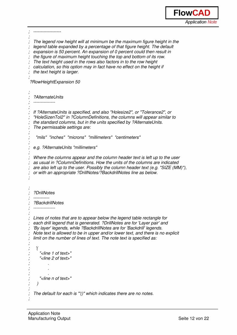
; ------------------- ; ; The legend row height will at minimum be the maximum figure height in the ; legend table expanded by a percentage of that figure height. The default ; expansion is 50 percent. An expansion of 0 percent could then result in ; the figure of maximum height touching the top and bottom of its row. ; The text height used in the rows also factors in to the row height ; calculation, so this option may in fact have no effect on the height if ; the text height is larger. ; ?RowHeightExpansion 50 ; ; ?AlternateUnits ; --------------- ; ; If ?AlternateUnits is specified, and also "Holesize2", or "Tolerance2", or ; "HoleSizenTol2" in ?ColumnDefinitions, the columns will appear similar to ; the standard columns, but in the units specified by ?AlternateUnits. ; The permissable settings are: ; ; "mils" "inches" "microns" "millimeters" "centimeters" ; ; e.g. ?AlternateUnits "millimeters" ; ; Where the columns appear and the column header text is left up to the user ; as usual in ?ColumnDefinitions. How the units of the columns are indicated ; are also left up to the user. Possibly the column header text (e.g. "SIZE (MM)"), ; or with an appropriate ?DrillNotes/?BackdrillNotes line as below. ; ; ; ?DrillNotes ; ----------- ; ?BackdrillNotes ; --------------- ; ; Lines of notes that are to appear below the legend table rectangle for ; each drill legend that is generated. ?DrillNotes are for 'Layer pair' and ; 'By layer' legends, while ?BackdrillNotes are for 'Backdrill' legends. ; Note text is allowed to be in upper and/or lower text, and there is no explicit ; limit on the number of lines of text. The note text is specified as: ; ; '( ; "<line 1 of text>" ; "<line 2 of text>" ; . ; . ; . ; "<line n of text>" ; ) ; ; The default for each is "'()" which indicates there are no notes. ;
Application Note Manufacturing Output Seite 13 von 22
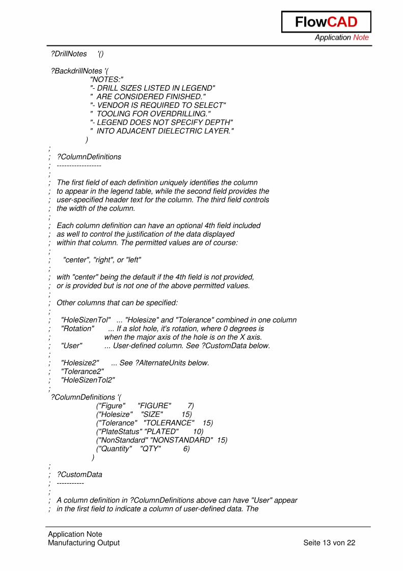
?DrillNotes '() ?BackdrillNotes '( "NOTES:" "- DRILL SIZES LISTED IN LEGEND" " ARE CONSIDERED FINISHED." "- VENDOR IS REQUIRED TO SELECT" " TOOLING FOR OVERDRILLING." "- LEGEND DOES NOT SPECIFY DEPTH" " INTO ADJACENT DIELECTRIC LAYER." ) ; ; ?ColumnDefinitions ; ------------------ ; ; The first field of each definition uniquely identifies the column ; to appear in the legend table, while the second field provides the ; user-specified header text for the column. The third field controls ; the width of the column. ; ; Each column definition can have an optional 4th field included ; as well to control the justification of the data displayed ; within that column. The permitted values are of course: ; ; "center", "right", or "left" ; ; with "center" being the default if the 4th field is not provided, ; or is provided but is not one of the above permitted values. ; ; Other columns that can be specified: ; ; "HoleSizenTol" ... "Holesize" and "Tolerance" combined in one column ; "Rotation" ... If a slot hole, it's rotation, where 0 degrees is ; when the major axis of the hole is on the X axis. ; "User" ... User-defined column. See ?CustomData below. ; ; "Holesize2" ... See ?AlternateUnits below. ; "Tolerance2" ; "HoleSizenTol2" ; ?ColumnDefinitions '( ("Figure" "FIGURE" 7) ("Holesize" "SIZE" 15) ("Tolerance" "TOLERANCE" 15) ("PlateStatus" "PLATED" 10) ("NonStandard" "NONSTANDARD" 15) ("Quantity" "QTY" 6) ) ; ; ?CustomData ; ----------- ; ; A column definition in ?ColumnDefinitions above can have "User" appear ; in the first field to indicate a column of user-defined data. The
Application Note Manufacturing Output Seite 14 von 22
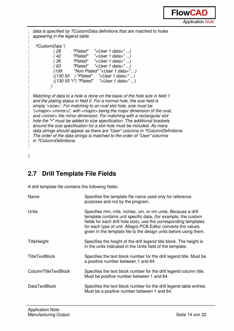
; data is specified by ?CustomData definitions that are matched to holes ; appearing in the legend table. ; ; ?CustomData '( ; ( 28 "Plated" "<User 1 data>" ...) ; ( 42 "Plated" "<User 1 data>" ...) ; ( 36 "Plated" "<User 1 data>" ...) ; ( 63 "Plated" "<User 1 data>" ...) ; (109 "Non Plated" "<User 1 data>" ...) ; ((130 50 ) "Plated" "<User 1 data>" ...) ; ((130 50 "r") "Plated" "<User 1 data>" ...) ; ) ; ; Matching of data to a hole is done on the basis of the hole size in field 1 ; and the plating status in field 2. For a normal hole, the size field is ; simply '<size>'. For matching to an oval slot hole, size must be ; '(<major> <minor>)', with <major> being the major dimension of the oval, ; and <minor> the minor dimension. For matching with a rectangular slot ; hole the "r" must be added to size specification. The additional brackets ; around the size specification for a slot hole must be included. As many ; data strings should appear as there are "User" columns in ?ColumnDefinitions. ; The order of the data strings is matched to the order of "User" columns ; in ?ColumnDefinitions. ; )
2.7 Drill Template File Fields A drill template file contains the following fields: Name Specifies the template file name used only for reference
purposes and not by the program. Units Specifies mm, mils, inches, um, or cm units. Because a drill
template contains unit specific data, (for example, the custom fields for each drill hole size), use the corresponding templates for each type of unit. Allegro PCB Editor converts the values given in the template file to the design units before using them.
TitleHeight Specifies the height of the drill legend title block. The height is
in the units indicated in the Units field of the template. TitleTextBlock Specifies the text block number for the drill legend title. Must be
a positive number between 1 and 64. ColumnTitleTextBlock Specifies the text block number for the drill legend column title.
Must be positive number between 1 and 64. DataTextBlock Specifies the text block number for the drill legend table entries.
Must be a positive number between 1 and 64.
Application Note Manufacturing Output Seite 15 von 22
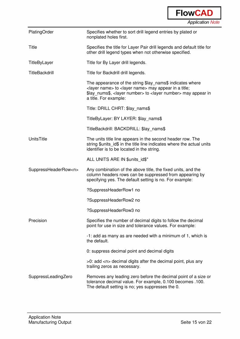
PlatingOrder Specifies whether to sort drill legend entries by plated or nonplated holes first.
Title Specifies the title for Layer Pair drill legends and default title for
other drill legend types when not otherwise specified. TitleByLayer Title for By Layer drill legends. TitleBackdrill Title for Backdrill drill legends.
The appearance of the string $lay_nams$ indicates where <layer name> to <layer name> may appear in a title; $lay_nums$, <layer number> to <layer number> may appear in a title. For example: Title: DRILL CHRT: $lay_nams$ TitleByLayer: BY LAYER: $lay_nams$ TitleBackdrill: BACKDRILL: $lay_nams$
UnitsTitle The units title line appears in the second header row. The
string $units_id$ in the title line indicates where the actual units identifier is to be located in the string.
ALL UNITS ARE IN $units_id$"
SuppressHeaderRow<n> Any combination of the above title, the fixed units, and the
column headers rows can be suppressed from appearing by specifying yes. The default setting is no. For example:
?SuppressHeaderRow1 no ?SuppressHeaderRow2 no ?SuppressHeaderRow3 no
Precision Specifies the number of decimal digits to follow the decimal
point for use in size and tolerance values. For example: -1: add as many as are needed with a minimum of 1, which is the default. 0: suppress decimal point and decimal digits >0: add <n> decimal digits after the decimal point, plus any trailing zeros as necessary.
SuppressLeadingZero Removes any leading zero before the decimal point of a size or
tolerance decimal value. For example, 0.100 becomes .100. The default setting is no; yes suppresses the 0.

Application Note Manufacturing Output Seite 16 von 22
FixedFigureHeight A non-zero value forces all figures to display with the same specified height, overriding the sizes defined in the padstacks. A zero value uses the padstack size definitions.
TableSlotRotations Separates each rotation for slot holes with identical figures into
its own entry in the legend table if you specify yes, which is the default. Otherwise, the figure shown has a 0 degree rotation (occurring when the slot hole’s major axis exists along the X axis) and the quantity shown is a sum of all rotations for that slot hole figure. The main figure for the individual slot figure instances shows the proper rotation, regardless of this setting.
ColumnDefinitions Specifies the details for each column in the drill legend. The
first field uniquely identifies the column; the second, the user specified header text; the third, the column width. Each column definition can have an optional fourth field to control the justification of the data displayed within that column. The permitted values are center, right, or left, with center default if the fourth field is not provided, or is not one of the above permitted values. A Rotation column can be optionally added to include slot holes’ rotation. A 0 degree rotation occurs when the slot hole’s major axis exists along the X axis. Each column has the following format:
Figure (FIGURE) has the drill figures with a character limit of 7. HoleSize (SIZE) has the drill hole size with a character limit of 15. Tolerance (TOLERANCE) specifies the positive or negative tolerance associated with the tool. Excluded if all holes have a positive or negative tolerance of zero, even when specified in the .dlt file with a character limit of 15. Plate Status (PLATED) specifies whether the hole is plated with a character limit of 10. NonStandard (NONSTANDARD) specifies whether the hole is manufactured with a nonstandard drill method. Excluded if no hole has a non-standard drill setting, even when specified in the .dlt file with a character limit of 15. Quantity specifies the number of holes on the board with the specified size. Multiple drill holes in multiple-drill vias are counted individually with a character limit of 6.
ForceToleranceColumn Hides the Tolerance column specified in ?ColumnDefinitions if
all holes have 0 tolerances (default), unless you specify yes to show it.
ShowTotalQuantity Displays the numeric hole quantity prefixed with TOTAL
HOLES: at the bottom of the Quantity column, outside the bounding legend table rectangle, if you specify yes. Otherwise defaults to no.
Application Note Manufacturing Output Seite 17 von 22
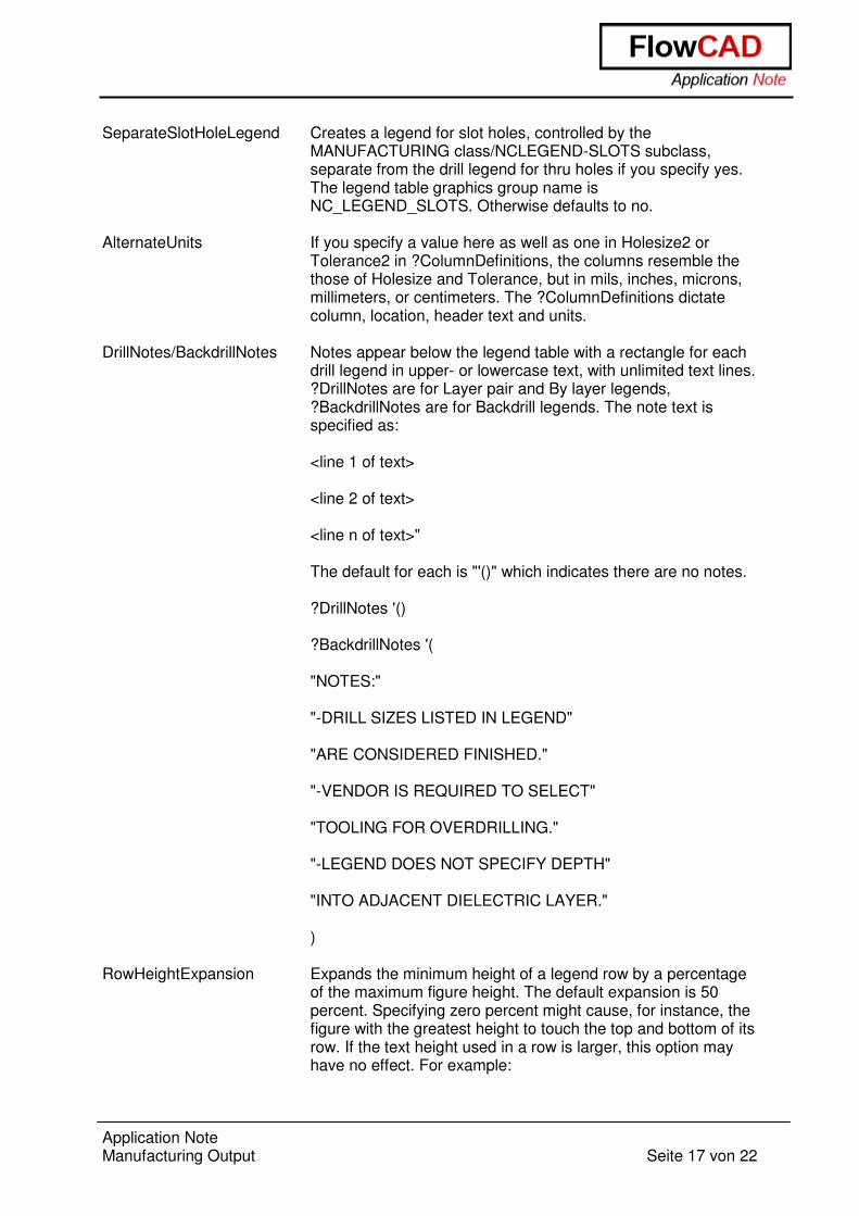
SeparateSlotHoleLegend Creates a legend for slot holes, controlled by the
MANUFACTURING class/NCLEGEND-SLOTS subclass, separate from the drill legend for thru holes if you specify yes. The legend table graphics group name is NC_LEGEND_SLOTS. Otherwise defaults to no.
AlternateUnits If you specify a value here as well as one in Holesize2 or
Tolerance2 in ?ColumnDefinitions, the columns resemble the those of Holesize and Tolerance, but in mils, inches, microns, millimeters, or centimeters. The ?ColumnDefinitions dictate column, location, header text and units.
DrillNotes/BackdrillNotes Notes appear below the legend table with a rectangle for each
drill legend in upper- or lowercase text, with unlimited text lines. ?DrillNotes are for Layer pair and By layer legends, ?BackdrillNotes are for Backdrill legends. The note text is specified as:
<line 1 of text> <line 2 of text> <line n of text>" The default for each is "'()" which indicates there are no notes. ?DrillNotes '() ?BackdrillNotes '( "NOTES:" "-DRILL SIZES LISTED IN LEGEND" "ARE CONSIDERED FINISHED." "-VENDOR IS REQUIRED TO SELECT" "TOOLING FOR OVERDRILLING." "-LEGEND DOES NOT SPECIFY DEPTH" "INTO ADJACENT DIELECTRIC LAYER." )
RowHeightExpansion Expands the minimum height of a legend row by a percentage
of the maximum figure height. The default expansion is 50 percent. Specifying zero percent might cause, for instance, the figure with the greatest height to touch the top and bottom of its row. If the text height used in a row is larger, this option may have no effect. For example:
Application Note Manufacturing Output Seite 18 von 22
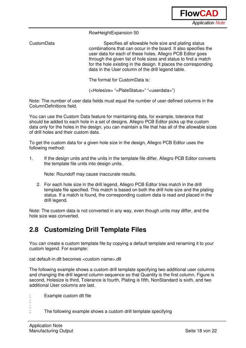
RowHeightExpansion 50 CustomData Specifies all allowable hole size and plating status
combinations that can occur in the board. It also specifies the user data for each of these holes. Allegro PCB Editor goes through the given list of hole sizes and status to find a match for the hole existing in the design. It places the corresponding data in the User column of the drill legend table.
The format for CustomData is:
(<Holesize> “<PlateStatus>” “<userdata>”)
Note: The number of user data fields must equal the number of user-defined columns in the ColumnDefinitions field. You can use the Custom Data feature for maintaining data, for example, tolerance that should be added to each hole in a set of designs. Allegro PCB Editor picks up the custom data only for the holes in the design, you can maintain a file that has all of the allowable sizes of drill holes and their custom data. To get the custom data for a given hole size in the design, Allegro PCB Editor uses the following method: 1. If the design units and the units in the template file differ, Allegro PCB Editor converts
the template file units into design units.
Note: Roundoff may cause inaccurate results.
2. For each hole size in the drill legend, Allegro PCB Editor tries match in the drill template file specified. This match is based on both the drill hole size and the plating status. If a match is found, the corresponding custom data is read and placed in the drill legend.
Note: The custom data is not converted in any way, even though units may differ, and the hole size was converted.
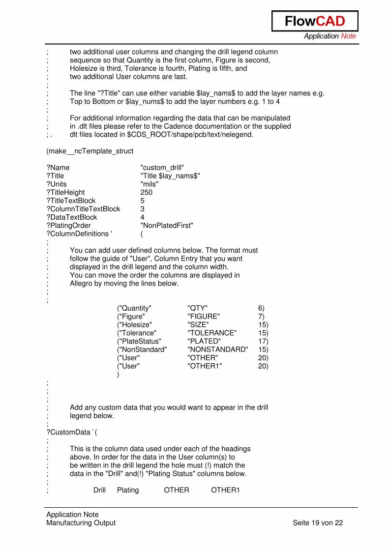
2.8 Customizing Drill Template Files You can create a custom template file by copying a default template and renaming it to your custom legend. For example: cat default-in.dlt becomes <custom name>.dlt The following example shows a custom drill template specifying two additional user columns and changing the drill legend column sequence so that Quantity is the first column, Figure is second, Holesize is third, Tolerance is fourth, Plating is fifth, NonStandard is sixth, and two additional User columns are last. ; Example custom dlt file ; ; ; The following example shows a custom drill template specifying
Application Note Manufacturing Output Seite 19 von 22
; two additional user columns and changing the drill legend column ; sequence so that Quantity is the first column, Figure is second, ; Holesize is third, Tolerance is fourth, Plating is fifth, and ; two additional User columns are last. ; ; The line "?Title" can use either variable $lay_nams$ to add the layer names e.g. ; Top to Bottom or $lay_nums$ to add the layer numbers e.g. 1 to 4 ; ; For additional information regarding the data that can be manipulated ; in .dlt files please refer to the Cadence documentation or the supplied ; . dlt files located in $CDS_ROOT/shape/pcb/text/nelegend. (make__ncTemplate_struct ?Name "custom_drill" ?Title "Title $lay_nams$" ?Units "mils" ?TitleHeight 250 ?TitleTextBlock 5 ?ColumnTitleTextBlock 3 ?DataTextBlock 4 ?PlatingOrder "NonPlatedFirst" ?ColumnDefinitions ' ( ; ; You can add user defined columns below. The format must ; follow the guide of "User", Column Entry that you want ; displayed in the drill legend and the column width. ; You can move the order the columns are displayed in ; Allegro by moving the lines below. ; ;
("Quantity" "QTY" 6) ("Figure" "FIGURE" 7) ("Holesize" "SIZE" 15) ("Tolerance" "TOLERANCE" 15) ("PlateStatus" "PLATED" 17) ("NonStandard" "NONSTANDARD" 15) ("User" "OTHER" 20) ("User" "OTHER1" 20) )
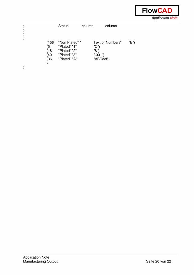
; ; ; ; Add any custom data that you would want to appear in the drill ; legend below. ; ?CustomData `( ; ; This is the column data used under each of the headings ; above. In order for the data in the User column(s) to ; be written in the drill legend the hole must (!) match the ; data in the "Drill" and(!) "Plating Status" columns below. ; ; Drill Plating OTHER OTHER1
Application Note Manufacturing Output Seite 20 von 22
; Status column column ; ; ;
(156 "Non Plated" " Text or Numbers" "B") (5 "Plated" "1" "C") (18 "Plated" "2" "8") (40 "Plated" "3" ".001") (36 "Plated" "A" "ABCdef") )
)
Application Note Manufacturing Output Seite 21 von 22
3 NC Route Running Manufacture – NC – NC Route (ncroute command) enables you to generate data for an NC router. The output file is an ASCII file in Excellon Format. Slot holes detected in the design are included in the NC Route output file. In contrast, NC Drill output produced by running the Manufacture – NC – NC Drill (nctape_full command) only applies to circular drill holes. When NC Route routes oval and rectangle slot holes, an appropriate tool is chosen from ncroutebits.txt using the following guidelines: Rectangle Slot: A tool size smaller than the minimum dimension of the rectangle must
exist to route a rectangle path with appropriate Excellon tool compensation.
Oval Slot A tool size that exactly matches the minor dimension of the oval must exist to route the oval as a single line path. Otherwise, a tool size smaller than the minor dimension must exist to route an oval path with appropriate Excellon tool compensation
3.1 Guidelines The ncroute command executes with the following expectations: - Each cutting path is drawn as a continuous series of lines and/or arcs. - There is no limit on the number of paths that may be specified. - Path direction can be specified. - If the design is defined in English units, the tool diameter is interpreted to be inches; if
Metric, then millimetres.
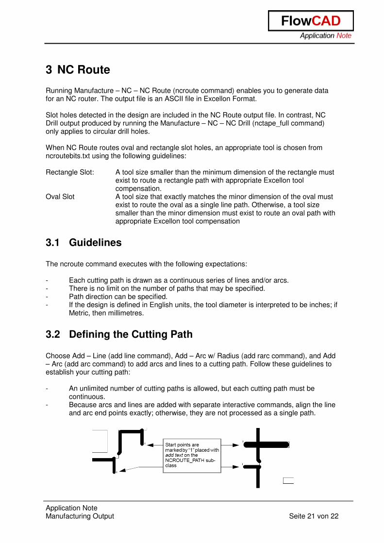
3.2 Defining the Cutting Path Choose Add – Line (add line command), Add – Arc w/ Radius (add rarc command), and Add – Arc (add arc command) to add arcs and lines to a cutting path. Follow these guidelines to establish your cutting path: - An unlimited number of cutting paths is allowed, but each cutting path must be
continuous. - Because arcs and lines are added with separate interactive commands, align the line
and arc end points exactly; otherwise, they are not processed as a single path.
Application Note Manufacturing Output Seite 22 von 22
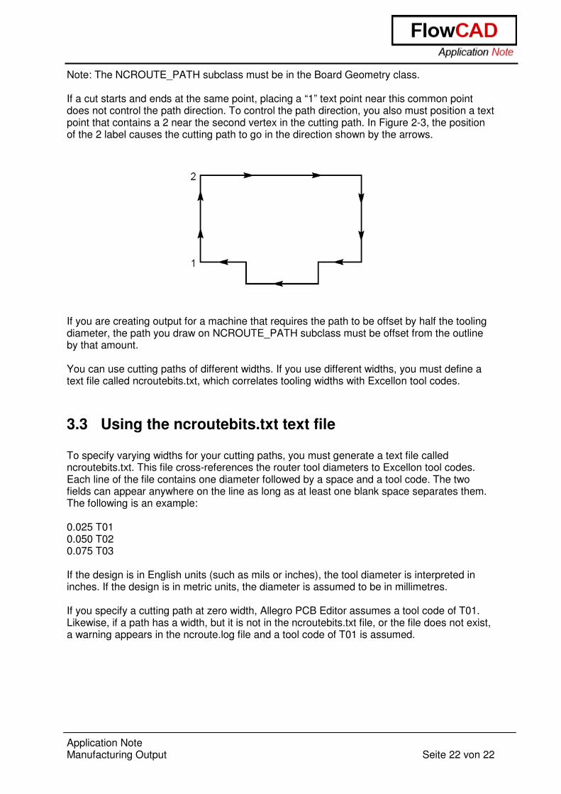
Note: The NCROUTE_PATH subclass must be in the Board Geometry class. If a cut starts and ends at the same point, placing a “1” text point near this common point does not control the path direction. To control the path direction, you also must position a text point that contains a 2 near the second vertex in the cutting path. In Figure 2-3, the position of the 2 label causes the cutting path to go in the direction shown by the arrows.
If you are creating output for a machine that requires the path to be offset by half the tooling diameter, the path you draw on NCROUTE_PATH subclass must be offset from the outline by that amount. You can use cutting paths of different widths. If you use different widths, you must define a text file called ncroutebits.txt, which correlates tooling widths with Excellon tool codes.
3.3 Using the ncroutebits.txt text file To specify varying widths for your cutting paths, you must generate a text file called ncroutebits.txt. This file cross-references the router tool diameters to Excellon tool codes. Each line of the file contains one diameter followed by a space and a tool code. The two fields can appear anywhere on the line as long as at least one blank space separates them. The following is an example: 0.025 T01 0.050 T02 0.075 T03 If the design is in English units (such as mils or inches), the tool diameter is interpreted in inches. If the design is in metric units, the diameter is assumed to be in millimetres. If you specify a cutting path at zero width, Allegro PCB Editor assumes a tool code of T01. Likewise, if a path has a width, but it is not in the ncroutebits.txt file, or the file does not exist, a warning appears in the ncroute.log file and a tool code of T01 is assumed.