Embed Size (px)
Citation preview
CIIT0394
CustomizationInstallation Instructions
February 16, 2007
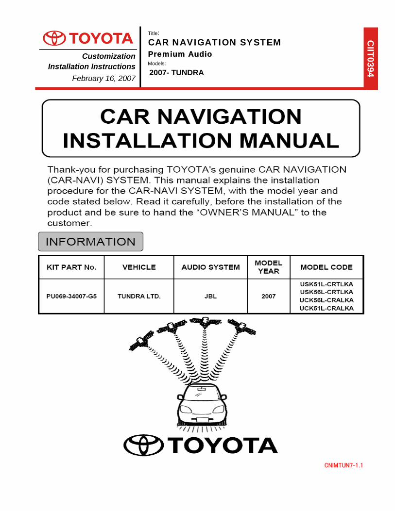
Title: CAR NAVIGATION SYSTEM
Premium Audio Models:
2007- TUNDRA
CNIMTUN7-1.1
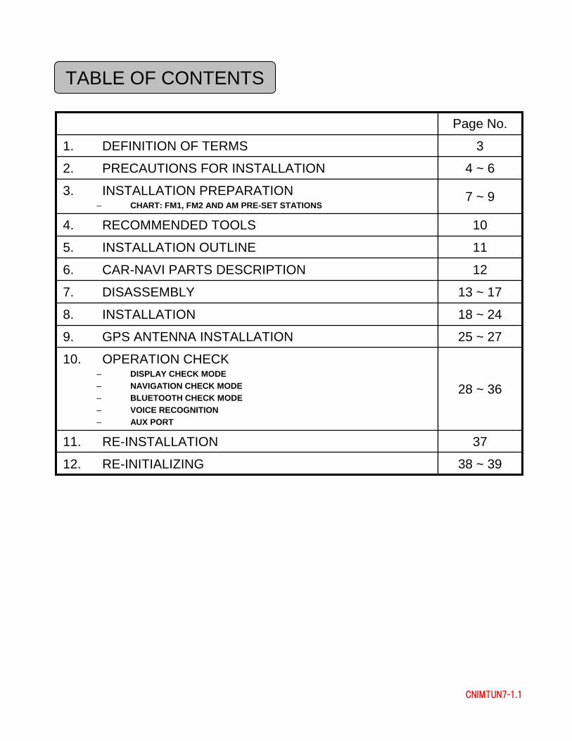
TABLE OF CONTENTS
126. CAR-NAVI PARTS DESCRIPTION
38 ~ 3912. RE-INITIALIZING
3711. RE-INSTALLATION
115. INSTALLATION OUTLINE
13 ~ 177. DISASSEMBLY
18 ~ 248. INSTALLATION
25 ~ 279. GPS ANTENNA INSTALLATION
28 ~ 36
10. OPERATION CHECK– DISPLAY CHECK MODE– NAVIGATION CHECK MODE– BLUETOOTH CHECK MODE– VOICE RECOGNITION– AUX PORT
104. RECOMMENDED TOOLS
7 ~ 93. INSTALLATION PREPARATION– CHART: FM1, FM2 AND AM PRE-SET STATIONS
4 ~ 62. PRECAUTIONS FOR INSTALLATION
31. DEFINITION OF TERMS
Page No.
3
CNIMTUN7-1.1
1. DEFINITION OF TERMS
WARNING: Describes precautions that should be observed, in order to prevent injury or death to the user during installation.
CAUTION: Describes precautions that should be observed, in order to prevent damage to the vehicle or its components, which may occur during installation if insufficient care is taken.
NOTE: Provides additional information that facilitates installation work.
FRONT, REAR, LEFT, RIGHT: Provides additional information that facilitates installation work.
TOOLS: Specifies the tools and equipment recommended for this process.
ESD: Contains parts and assemblies susceptible to damage by Electrostatic Discharge (ESD).
4
CNIMTUN7-1.1
1. Contents given in the WARNING and CAUTION in this manual must becarefully followed during the installation. If they are ignored, functions of the CAR-NAVI system are hindered, as well as personal injury or damage to the vehicle may result. Always carry out the installation in accordance with the WARNING and CAUTION as noted.
2. When the vehicle parts are removed, keep the tapping screws, bolts and nuts organized so that the re-assembly will proceed correctly.
3. Do NOT remove vehicle parts except for those that are specified in this manual.
4. Not all digital photographs depicted in this Installation Manual, will reflect the current model and model year vehicle.
2. PRECAUTIONS FOR INSTALLATION
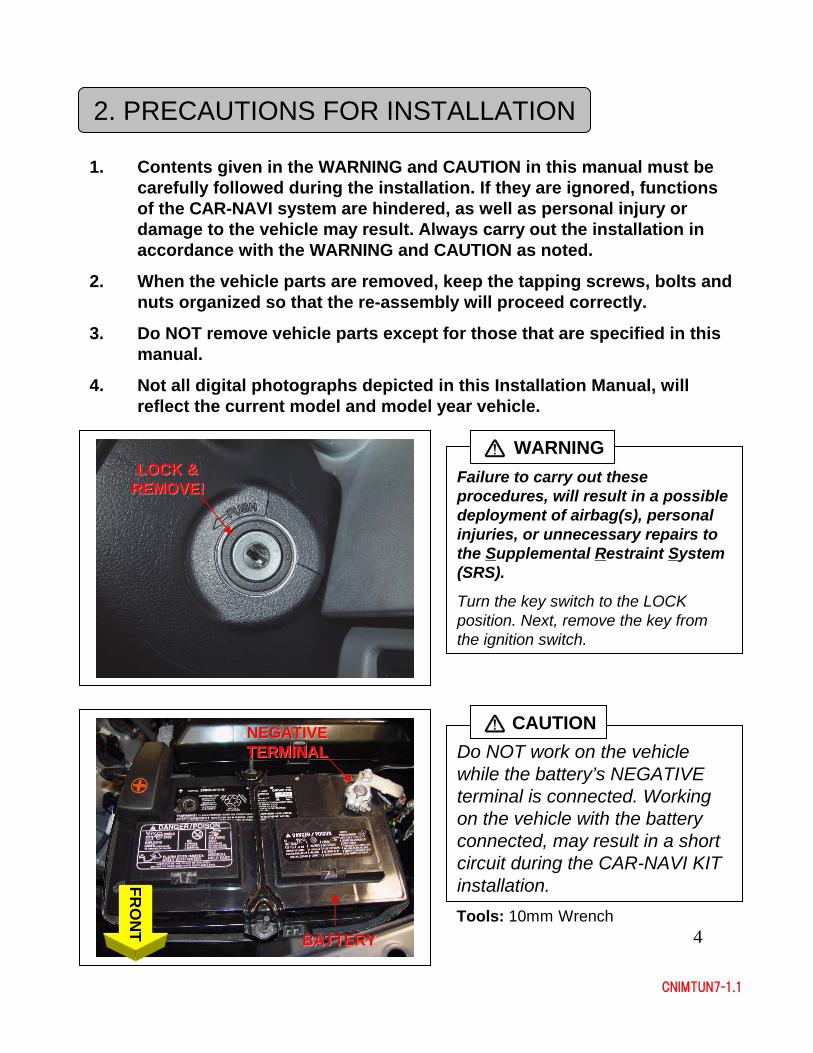
Failure to carry out these procedures, will result in a possible deployment of airbag(s), personal injuries, or unnecessary repairs to the Supplemental Restraint System (SRS).
Turn the key switch to the LOCK position. Next, remove the key from the ignition switch.
WARNING
Do NOT work on the vehicle while the battery’s NEGATIVE terminal is connected. Working on the vehicle with the battery connected, may result in a short circuit during the CAR-NAVI KIT installation.
CAUTION
BATTERYBATTERY
NEGATIVE NEGATIVE TERMINALTERMINAL
FRO
NT Tools: 10mm Wrench
LOCK & LOCK & REMOVE!REMOVE!
5
CNIMTUN7-1.1
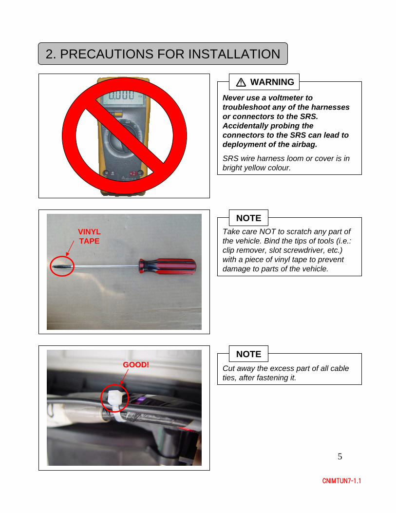
Take care NOT to scratch any part of the vehicle. Bind the tips of tools (i.e.: clip remover, slot screwdriver, etc.) with a piece of vinyl tape to prevent damage to parts of the vehicle.
Cut away the excess part of all cable ties, after fastening it.
NOTE
VINYL VINYL TAPETAPE
GOOD!GOOD!
NOTE
Never use a voltmeter to troubleshoot any of the harnesses or connectors to the SRS. Accidentally probing the connectors to the SRS can lead to deployment of the airbag.
SRS wire harness loom or cover is in bright yellow colour.
WARNING
2. PRECAUTIONS FOR INSTALLATION
6
CNIMTUN7-1.1
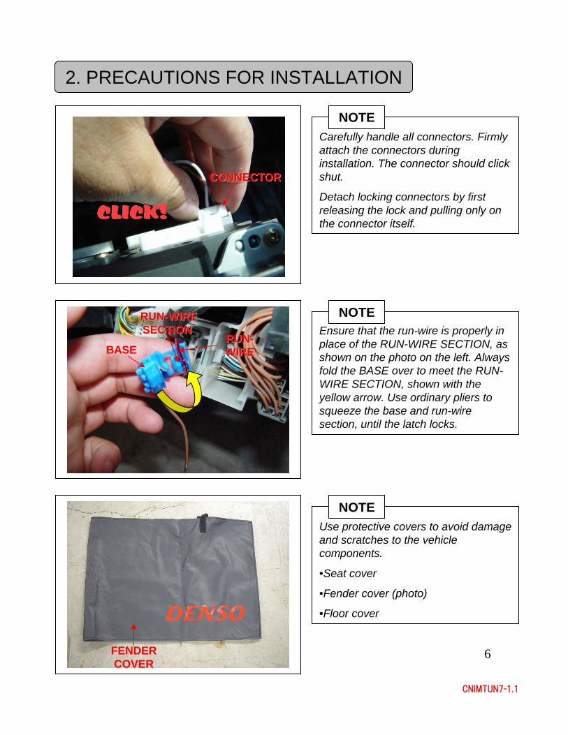
Ensure that the run-wire is properly in place of the RUN-WIRE SECTION, as shown on the photo on the left. Always fold the BASE over to meet the RUN-WIRE SECTION, shown with the yellow arrow. Use ordinary pliers to squeeze the base and run-wire section, until the latch locks.
NOTE
Carefully handle all connectors. Firmly attach the connectors during installation. The connector should click shut.
Detach locking connectors by first releasing the lock and pulling only on the connector itself.
NOTE
CONNECTORCONNECTOR
2. PRECAUTIONS FOR INSTALLATION
RUNRUN--WIRE WIRE SECTIONSECTION
RUNRUN--WIREWIREBASEBASE
FENDER FENDER COVERCOVER
Use protective covers to avoid damage and scratches to the vehicle components.
•Seat cover
•Fender cover (photo)
•Floor cover
NOTE
7
CNIMTUN7-1.1
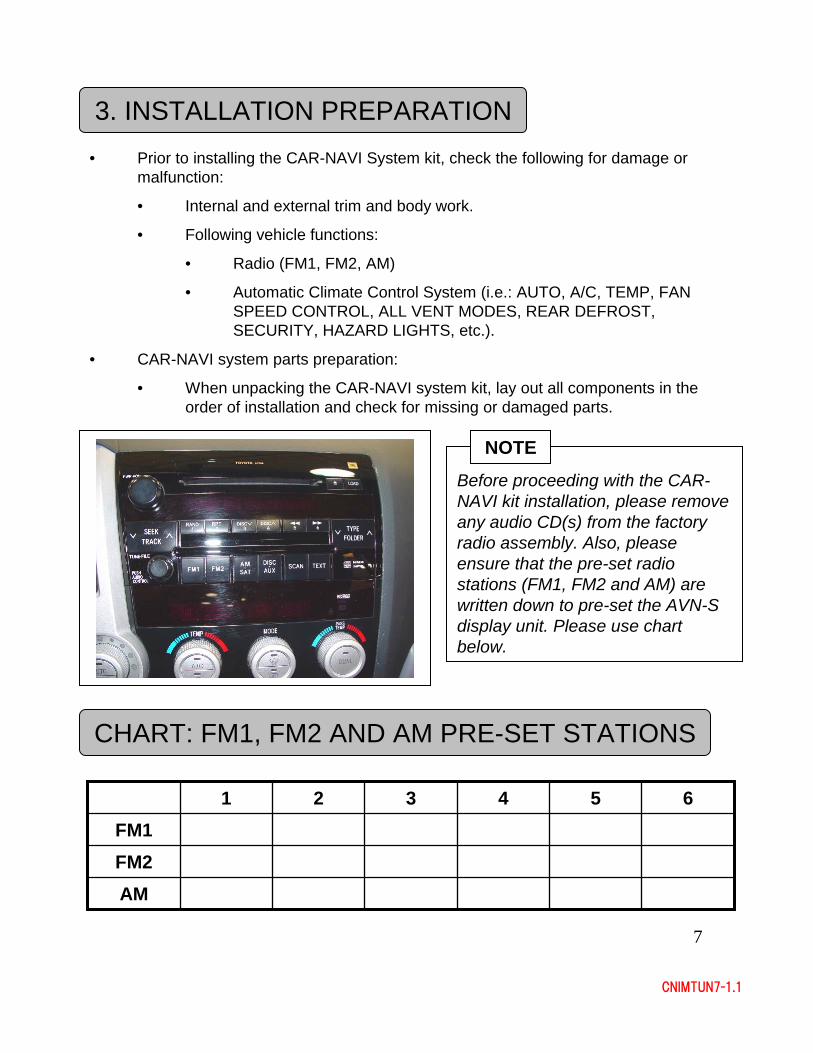
Before proceeding with the CAR-NAVI kit installation, please remove any audio CD(s) from the factory radio assembly. Also, please ensure that the pre-set radio stations (FM1, FM2 and AM) are written down to pre-set the AVN-S display unit. Please use chart below.
NOTE
CHART: FM1, FM2 AND AM PRE-SET STATIONS
AMFM2FM1
654321
3. INSTALLATION PREPARATION• Prior to installing the CAR-NAVI System kit, check the following for damage or
malfunction:
• Internal and external trim and body work.
• Following vehicle functions:
• Radio (FM1, FM2, AM)
• Automatic Climate Control System (i.e.: AUTO, A/C, TEMP, FAN SPEED CONTROL, ALL VENT MODES, REAR DEFROST, SECURITY, HAZARD LIGHTS, etc.).
• CAR-NAVI system parts preparation:
• When unpacking the CAR-NAVI system kit, lay out all components in the order of installation and check for missing or damaged parts.
8
CNIMTUN7-1.1
3. INSTALLATION PREPARATION
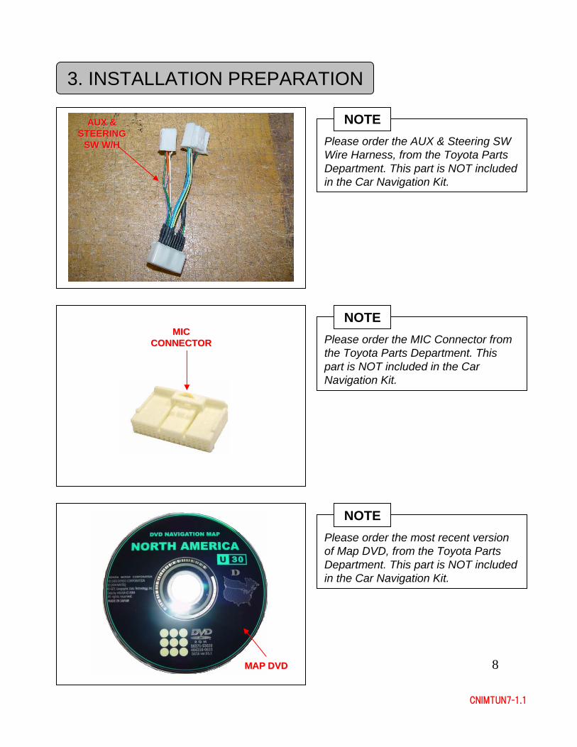
Please order the AUX & Steering SW Wire Harness, from the Toyota Parts Department. This part is NOT included in the Car Navigation Kit.
NOTEAUX & AUX & STEERING STEERING
SW W/HSW W/H
Please order the most recent version of Map DVD, from the Toyota Parts Department. This part is NOT included in the Car Navigation Kit.
NOTE
MAP DVDMAP DVD
Please order the MIC Connector from the Toyota Parts Department. This part is NOT included in the Car Navigation Kit.
NOTEMIC MIC
CONNECTORCONNECTOR
9
CNIMTUN7-1.1
3. INSTALLATION PREPARATION
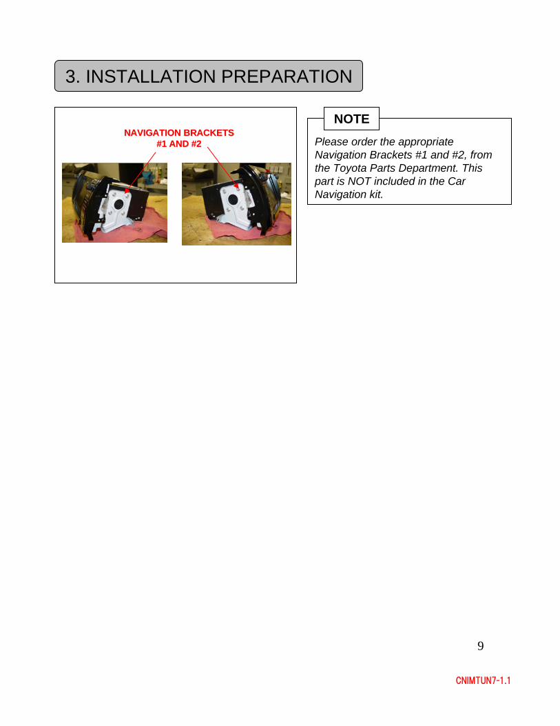
Please order the appropriate Navigation Brackets #1 and #2, from the Toyota Parts Department. This part is NOT included in the Car Navigation kit.
NOTENAVIGATION BRACKETS NAVIGATION BRACKETS
#1 AND #2#1 AND #2
10
CNIMTUN7-1.1
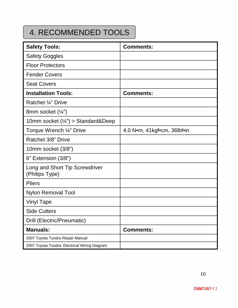
4. RECOMMENDED TOOLS
Drill (Electric/Pneumatic)
Pliers
2007 Toyota Tundra: Electrical Wiring Diagram
Nylon Removal Tool
2007 Toyota Tundra Repair Manual
Long and Short Tip Screwdriver (Philips Type)
Comments:Manuals:
Comments:Installation Tools:Ratchet ¼” Drive
8mm socket (¼”)
10mm socket (¼”) > Standard&Deep
4.0 N•m, 41kgf•cm, 36lbf•inTorque Wrench ¼” Drive
Ratchet 3/8” Drive
10mm socket (3/8”)
6” Extension (3/8”)
Vinyl Tape
Side Cutters
Seat Covers
Fender Covers
Floor Protectors
Safety Goggles
Comments:Safety Tools:
11
CNIMTUN7-1.1
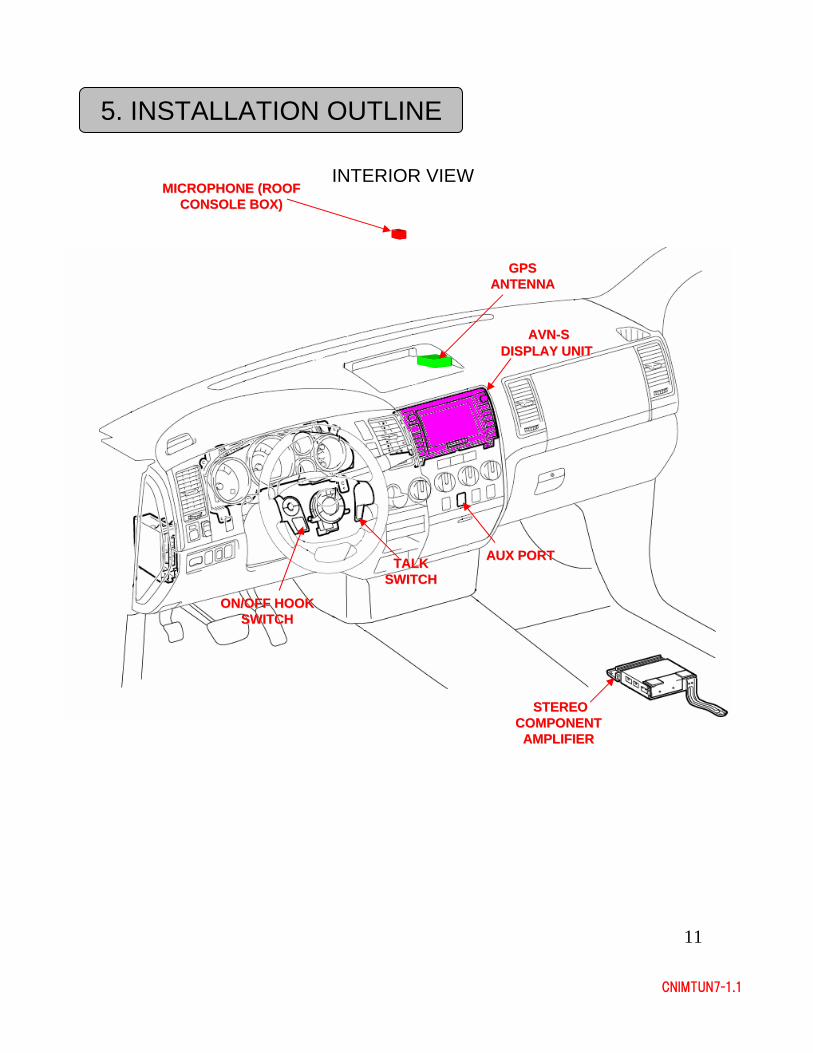
5. INSTALLATION OUTLINE
INTERIOR VIEW
AVNAVN--S S DISPLAY UNITDISPLAY UNIT
GPS GPS ANTENNAANTENNA
MICROPHONE (ROOF MICROPHONE (ROOF CONSOLE BOX)CONSOLE BOX)
AUX PORTAUX PORTTALK TALK SWITCHSWITCH
ON/OFF HOOK ON/OFF HOOK SWITCHSWITCH
STEREO STEREO COMPONENT COMPONENT
AMPLIFIERAMPLIFIER
12
CNIMTUN7-1.1
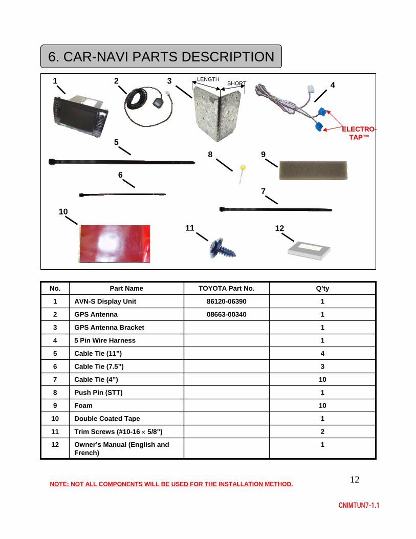
6. CAR-NAVI PARTS DESCRIPTION
3Cable Tie (7.5”)6
2Trim Screws (#10-16 × 5/8”)11
1Owner’s Manual (English and French)
12
1Double Coated Tape10
10Foam9
1Push Pin (STT)8
10Cable Tie (4”)7
4Cable Tie (11”)5
1GPS Antenna Bracket3
15 Pin Wire Harness4
108663-00340GPS Antenna2
186120-06390AVN-S Display Unit1
Q’tyTOYOTA Part No.Part NameNo.
1 2
5
3
9
ELECTROELECTRO--TAPTAP™™
6
10
1211
NOTE: NOT ALL COMPONENTS WILL BE USED FOR THE INSTALLATION METHOD.
LENGTHSHORT
8
4
7
13
CNIMTUN7-1.1
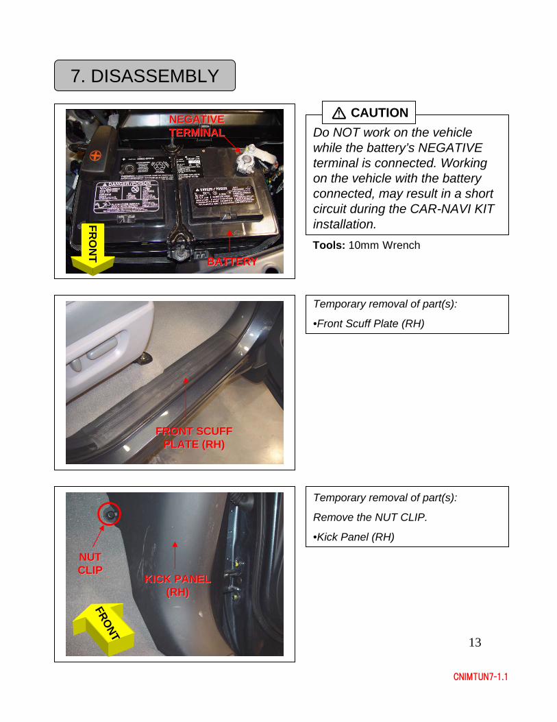
7. DISASSEMBLY
Do NOT work on the vehicle while the battery’s NEGATIVE terminal is connected. Working on the vehicle with the battery connected, may result in a short circuit during the CAR-NAVI KIT installation.
CAUTION
BATTERYBATTERY
NEGATIVE NEGATIVE TERMINALTERMINAL
FRO
NT Tools: 10mm Wrench
Temporary removal of part(s):
•Front Scuff Plate (RH)
FRONT SCUFF FRONT SCUFF PLATE (RH)PLATE (RH)
Temporary removal of part(s):
Remove the NUT CLIP.
•Kick Panel (RH)
NUT NUT CLIPCLIP
FRONT
KICK PANEL KICK PANEL (RH)(RH)
14
CNIMTUN7-1.1
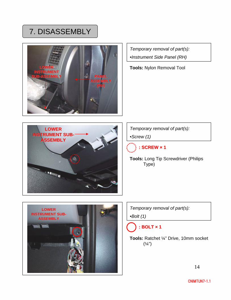
7. DISASSEMBLY
Temporary removal of part(s):
•Instrument Side Panel (RH)
Tools: Nylon Removal Tool
PANEL PANEL ASSEMBLY ASSEMBLY
(RH)(RH)
LOWER LOWER INSTRUMENT INSTRUMENT
SUBSUB--ASSEMBLYASSEMBLY
Temporary removal of part(s):
•Screw (1)
Tools: Long Tip Screwdriver (Philips Type)
: SCREW : SCREW ×× 11
LOWER LOWER INSTRUMENT SUBINSTRUMENT SUB--
ASSEMBLYASSEMBLY
Temporary removal of part(s):
•Bolt (1)
Tools: Ratchet ¼” Drive, 10mm socket (¼”)
: BOLT : BOLT ×× 11
LOWER LOWER INSTRUMENT SUBINSTRUMENT SUB--
ASSEMBLYASSEMBLY
15
CNIMTUN7-1.1
7. DISASSEMBLY
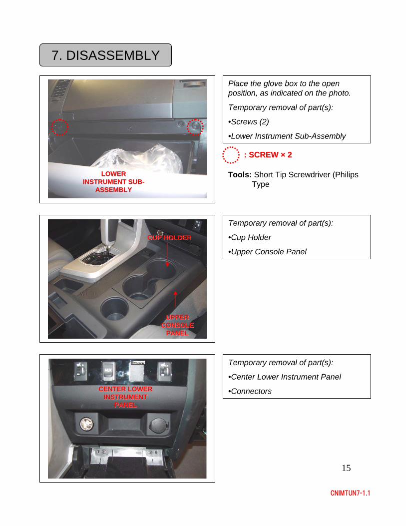
Place the glove box to the open position, as indicated on the photo.
Temporary removal of part(s):
•Screws (2)
•Lower Instrument Sub-Assembly
Tools: Short Tip Screwdriver (Philips Type
: SCREW : SCREW ×× 22
LOWER LOWER INSTRUMENT SUBINSTRUMENT SUB--
ASSEMBLYASSEMBLY
Temporary removal of part(s):
•Cup Holder
•Upper Console Panel
Temporary removal of part(s):
•Center Lower Instrument Panel
•Connectors
CUP HOLDERCUP HOLDER
SHIFT KNOBSHIFT KNOB
UPPER UPPER CONSOLE CONSOLE
PANELPANEL
CENTER LOWER CENTER LOWER INSTRUMENT INSTRUMENT
PANELPANEL
16
CNIMTUN7-1.1
7. DISASSEMBLY
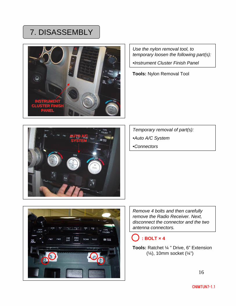
Use the nylon removal tool, to temporary loosen the following part(s):
•Instrument Cluster Finish Panel
Tools: Nylon Removal Tool
INSTRUMENT INSTRUMENT CLUSTER FINISH CLUSTER FINISH
PANELPANEL
Temporary removal of part(s):
•Auto A/C System
•Connectors
AUTO A/C AUTO A/C SYSTEMSYSTEM
Remove 4 bolts and then carefully remove the Radio Receiver. Next, disconnect the connector and the two antenna connectors.
: BOLT × 4
Tools: Ratchet ¼ ” Drive, 6” Extension (¼), 10mm socket (¼”)
17
CNIMTUN7-1.1
7. DISASSEMBLY
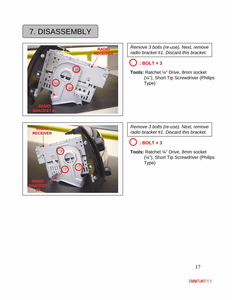
Remove 3 bolts (re-use). Next, remove radio bracket #1. Discard this bracket.
Remove 3 bolts (re-use). Next, remove radio bracket #1. Discard this bracket.
Tools: Ratchet ¼” Drive, 8mm socket (¼”), Short Tip Screwdriver (Philips Type)
RADIO RADIO BRACKET #1BRACKET #1
RADIO RADIO RECEIVERRECEIVER
: BOLT × 3
RADIO RADIO BRACKET #2BRACKET #2
RADIO RADIO RECEIVER RECEIVER W/ HEATER W/ HEATER CONTROLCONTROL
Tools: Ratchet ¼” Drive, 8mm socket (¼”), Short Tip Screwdriver (Philips Type)
: BOLT × 3
RADIO RADIO BRACKET BRACKET
#2#2
RADIO RADIO RECEIVERRECEIVER
18
CNIMTUN7-1.1
8. INSTALLATION
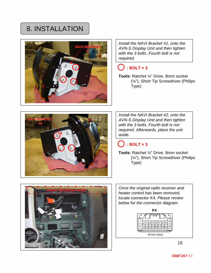
Install the NAVI Bracket #1, onto the AVN-S Display Unit and then tighten with the 3 bolts. Fourth bolt is not required.
Tools: Ratchet ¼” Drive, 8mm socket (¼”), Short Tip Screwdriver (Philips Type)
: BOLT × 3
NAVI BRACKET NAVI BRACKET #1#1
Install the NAVI Bracket #2, onto the AVN-S Display Unit and then tighten with the 3 bolts. Fourth bolt is not required. Afterwards, place the unit aside.
Tools: Ratchet ¼” Drive, 8mm socket (¼”), Short Tip Screwdriver (Philips Type)
: BOLT × 3
NAVI BRACKET NAVI BRACKET #2#2
K4K4
(Front View)
Once the original radio receiver and heater control has been removed, locate connector K4. Please review below for the connector diagram.
RADIO RECEIVER AREARADIO RECEIVER AREA
19
CNIMTUN7-1.1
8. INSTALLATION
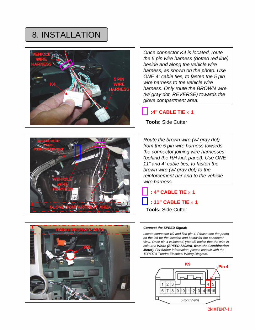
Route the brown wire (w/ gray dot) from the 5 pin wire harness towards the connector joining wire harnesses (behind the RH kick panel). Use ONE 11” and 4” cable ties, to fasten the brown wire (w/ gray dot) to the reinforcement bar and to the vehicle wire harness.
Once connector K4 is located, route the 5 pin wire harness (dotted red line) beside and along the vehicle wire harness, as shown on the photo. Use ONE 4” cable ties, to fasten the 5 pin wire harness to the vehicle wire harness. Only route the BROWN wire (w/ gray dot, REVERSE) towards the glove compartment area.
:4” CABLE TIE × 1
Tools: Side Cutter
K4K45 PIN 5 PIN WIRE WIRE
HARNESSHARNESS
VEHICLE VEHICLE WIRE WIRE
HARNESSHARNESS
GLOVE COMPARTMENT AREAGLOVE COMPARTMENT AREA
Connect the SPEED Signal:
Locate connector K9 and find pin 4. Please see the photo on the left for the location and below for the connector view. Once pin 4 is located, you will notice that the wire is coloured White (SPEED SIGNAL from the Combination Meter). For further information, please consult with the TOYOTA Tundra Electrical Wiring Diagram.
K9K9
K9K9
(Front View)
Pin 4Pin 4
: 4” CABLE TIE × 1
Tools: Side Cutter
VEHICLE VEHICLE WIRE WIRE
HARNESSHARNESS
RADIO RECEIVER AREARADIO RECEIVER AREA
: 11” CABLE TIE × 1
INSTRUMENT INSTRUMENT PANEL PANEL
REINFORCEMENTREINFORCEMENT
20
CNIMTUN7-1.1
8. INSTALLATION
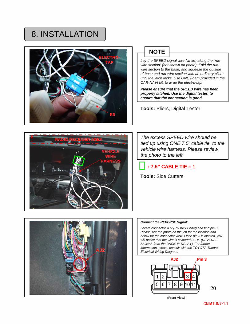
Lay the SPEED signal wire (white) along the “run-wire section” (not shown on photo). Fold the run-wire section to the base, and squeeze the outside of base and run-wire section with an ordinary pliers until the latch locks. Use ONE Foam provided in the CAR-NAVI kit, to wrap the electro-tap.
Please ensure that the SPEED wire has been properly latched. Use the digital tester, to ensure that the connection is good.
Tools: Pliers, Digital Tester
ELECTROELECTRO--TAPTAP
K9K9
Connect the REVERSE Signal:
Locate connector AJ2 (RH Kick Panel) and find pin 3. Please see the photo on the left for the location and below for the connector view. Once pin 3 is located, you will notice that the wire is coloured BLUE (REVERSE SIGNAL from the BACKUP RELAY). For further information, please consult with the TOYOTA Tundra Electrical Wiring Diagram.AJ2AJ2
AJ2AJ2
(Front View)
Pin 3Pin 3
The excess SPEED wire should be tied up using ONE 7.5” cable tie, to the vehicle wire harness. Please review the photo to the left.
Tools: Side Cutters
VEHICLE VEHICLE WIRE WIRE
HARNESSHARNESS
RADIO RECEIVER AREARADIO RECEIVER AREA
: 7.5” CABLE TIE × 1
NOTE
21
CNIMTUN7-1.1
8. INSTALLATION
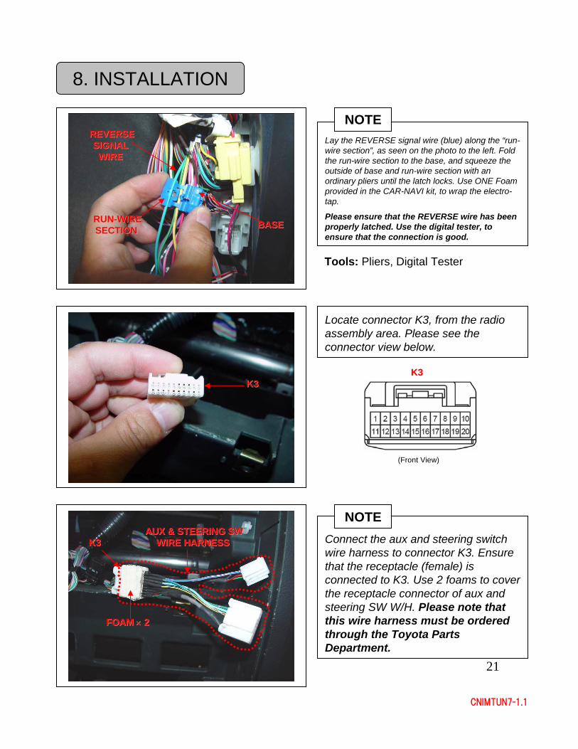
Lay the REVERSE signal wire (blue) along the “run-wire section”, as seen on the photo to the left. Fold the run-wire section to the base, and squeeze the outside of base and run-wire section with an ordinary pliers until the latch locks. Use ONE Foam provided in the CAR-NAVI kit, to wrap the electro-tap.
Please ensure that the REVERSE wire has been properly latched. Use the digital tester, to ensure that the connection is good.
Tools: Pliers, Digital Tester
RUNRUN--WIRE WIRE SECTIONSECTION
REVERSE REVERSE SIGNAL SIGNAL
WIREWIRE
BASEBASE
Connect the aux and steering switch wire harness to connector K3. Ensure that the receptacle (female) is connected to K3. Use 2 foams to cover the receptacle connector of aux and steering SW W/H. Please note that this wire harness must be ordered through the Toyota Parts Department.
K3K3
Locate connector K3, from the radio assembly area. Please see the connector view below.
K3K3K3K3
(Front View)
AUX & STEERING SW AUX & STEERING SW WIRE HARNESSWIRE HARNESS
NOTE
FOAM FOAM ×× 22
NOTE
22
CNIMTUN7-1.1
8. INSTALLATION
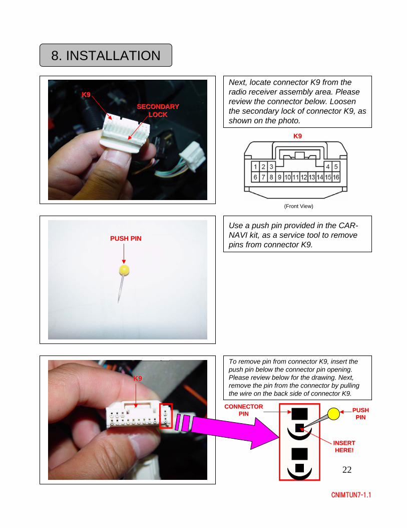
Next, locate connector K9 from the radio receiver assembly area. Please review the connector below. Loosen the secondary lock of connector K9, as shown on the photo.
K9K9
(Front View)
K9K9
SECONDARY SECONDARY LOCKLOCK
Use a push pin provided in the CAR-NAVI kit, as a service tool to remove pins from connector K9.
PUSH PINPUSH PIN
To remove pin from connector K9, insert the push pin below the connector pin opening. Please review below for the drawing. Next, remove the pin from the connector by pulling the wire on the back side of connector K9.
K9K9
PUSH PUSH PINPIN
INSERT INSERT HERE!HERE!
CONNECTOR CONNECTOR PINPIN
23
CNIMTUN7-1.1
8. INSTALLATION
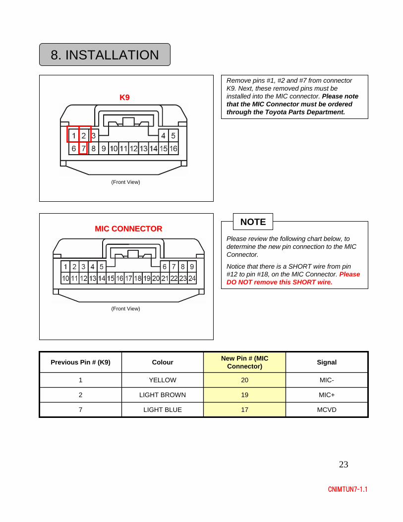
Remove pins #1, #2 and #7 from connector K9. Next, these removed pins must be installed into the MIC connector. Please note that the MIC Connector must be ordered through the Toyota Parts Department.
K9K9
(Front View)
Please review the following chart below, to determine the new pin connection to the MIC Connector.
Notice that there is a SHORT wire from pin #12 to pin #18, on the MIC Connector. Please DO NOT remove this SHORT wire.
MIC CONNECTORMIC CONNECTOR
(Front View)
MCVD17LIGHT BLUE7
MIC+19LIGHT BROWN2
MIC-20YELLOW1
SignalNew Pin # (MIC Connector)ColourPrevious Pin # (K9)
NOTE
24
CNIMTUN7-1.1
8. INSTALLATION
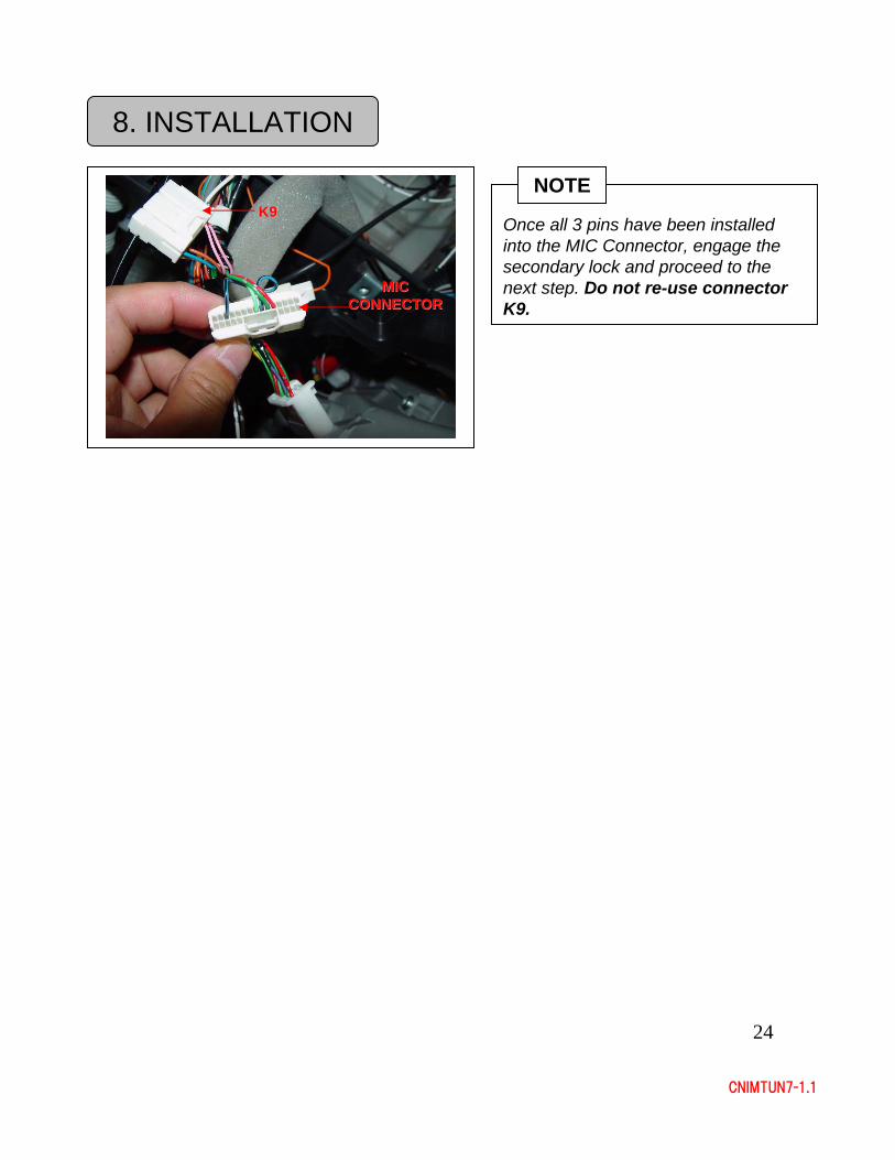
Once all 3 pins have been installed into the MIC Connector, engage the secondary lock and proceed to the next step. Do not re-use connector K9.
MIC MIC CONNECTORCONNECTOR
NOTEK9K9
25
CNIMTUN7-1.1
9. GPS ANTENNA INSTALLATION
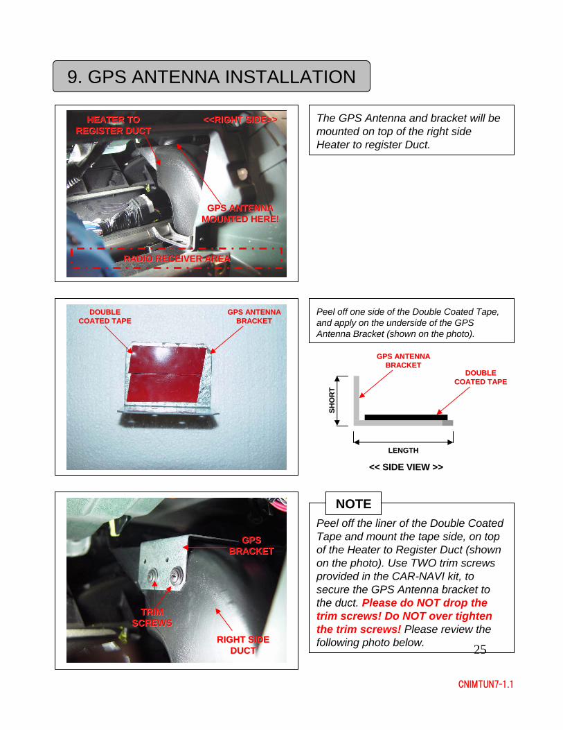
The GPS Antenna and bracket will be mounted on top of the right side Heater to register Duct.
HEATER TO HEATER TO REGISTER DUCTREGISTER DUCT
GPS ANTENNA GPS ANTENNA MOUNTED HERE!MOUNTED HERE!
<<RIGHT SIDE>><<RIGHT SIDE>>
Peel off one side of the Double Coated Tape, and apply on the underside of the GPS Antenna Bracket (shown on the photo).
GPS ANTENNA GPS ANTENNA BRACKETBRACKET
DOUBLE DOUBLE COATED TAPECOATED TAPE
LENGTHLENGTH
SHO
RT
SHO
RT
<< SIDE VIEW >><< SIDE VIEW >>
GPS ANTENNA GPS ANTENNA BRACKETBRACKET
DOUBLE DOUBLE COATED TAPECOATED TAPE
RADIO RECEIVER AREARADIO RECEIVER AREA
Peel off the liner of the Double Coated Tape and mount the tape side, on top of the Heater to Register Duct (shown on the photo). Use TWO trim screws provided in the CAR-NAVI kit, to secure the GPS Antenna bracket to the duct. Please do NOT drop the trim screws! Do NOT over tighten the trim screws! Please review the following photo below. RIGHT SIDE RIGHT SIDE
DUCTDUCT
GPS GPS BRACKETBRACKET
NOTE
TRIM TRIM SCREWSSCREWS
26
CNIMTUN7-1.1
9. GPS ANTENNA INSTALLATION
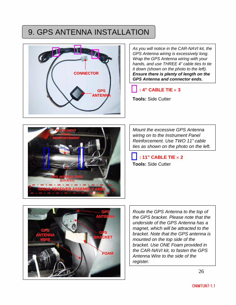
As you will notice in the CAR-NAVI kit, the GPS Antenna wiring is excessively long. Wrap the GPS Antenna wiring with your hands, and use THREE 4” cable ties to tie it down (shown on the photo to the left). Ensure there is plenty of length on the GPS Antenna and connector ends.
: 4” CABLE TIE × 3
Tools: Side Cutter
Mount the excessive GPS Antenna wiring on to the Instrument Panel Reinforcement. Use TWO 11” cable ties as shown on the photo on the left.
INSTRUMENT INSTRUMENT PANEL PANEL
REINFORCEMENTREINFORCEMENT
: 11” CABLE TIE × 2Tools: Side Cutter
GPS ANTENNA WIRE GPS ANTENNA WIRE (EXCESS)(EXCESS)
RADIO RECEIVER ASSEMBLY AREARADIO RECEIVER ASSEMBLY AREA
Route the GPS Antenna to the top of the GPS bracket. Please note that the underside of the GPS Antenna has a magnet, which will be attracted to the bracket. Note that the GPS antenna is mounted on the top side of the bracket. Use ONE Foam provided in the CAR-NAVI kit, to fasten the GPS Antenna Wire to the side of the register.
GPS GPS BRACKETBRACKET
GPS GPS ANTENNAANTENNA
GPS GPS ANTENNA ANTENNA
WIREWIRE
FOAMFOAM
GPS GPS ANTENNAANTENNA
CONNECTORCONNECTOR
27
CNIMTUN7-1.1
9. GPS ANTENNA INSTALLATION
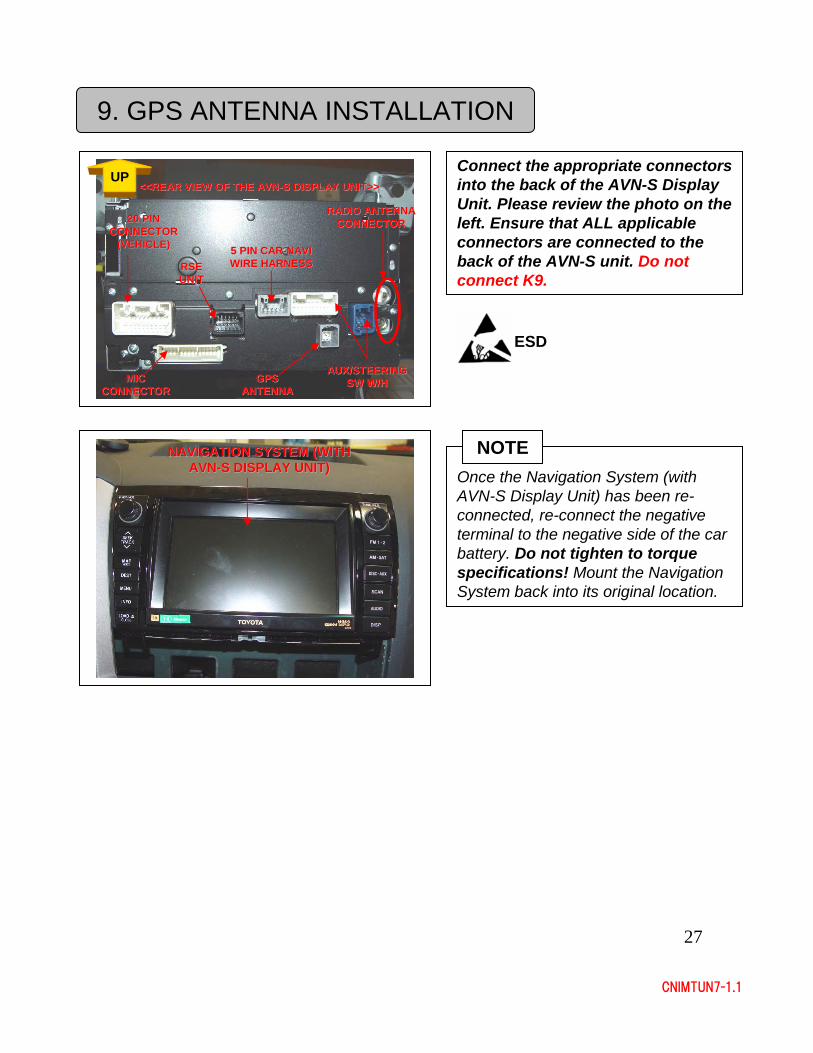
Connect the appropriate connectors into the back of the AVN-S Display Unit. Please review the photo on the left. Ensure that ALL applicable connectors are connected to the back of the AVN-S unit. Do not connect K9.
GPS GPS ANTENNAANTENNA
<<REAR VIEW OF THE AVN<<REAR VIEW OF THE AVN--S DISPLAY UNIT>>S DISPLAY UNIT>>
20 PIN 20 PIN CONNECTOR CONNECTOR
(VEHICLE)(VEHICLE)
UP
5 PIN CAR5 PIN CAR--NAVI NAVI WIRE HARNESSWIRE HARNESS
RADIO ANTENNA RADIO ANTENNA CONNECTORCONNECTOR
MIC MIC CONNECTORCONNECTOR
RSE RSE UNITUNIT
AUX/STEERING AUX/STEERING SW W/HSW W/H
ESD
Once the Navigation System (with AVN-S Display Unit) has been re-connected, re-connect the negative terminal to the negative side of the car battery. Do not tighten to torque specifications! Mount the Navigation System back into its original location.
NOTENAVIGATION SYSTEM (WITH NAVIGATION SYSTEM (WITH AVNAVN--S DISPLAY UNIT)S DISPLAY UNIT)
28
CNIMTUN7-1.1
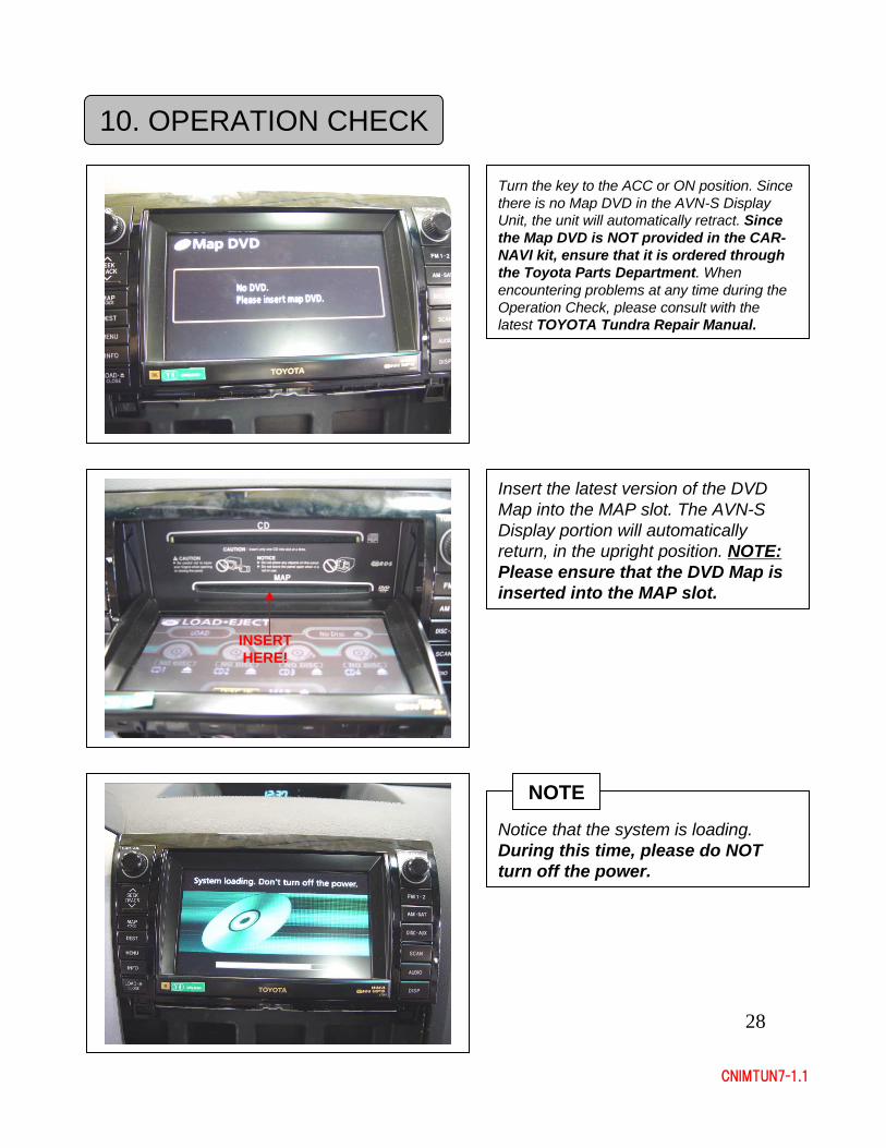
Notice that the system is loading. During this time, please do NOT turn off the power.
NOTE
10. OPERATION CHECK
Turn the key to the ACC or ON position. Since there is no Map DVD in the AVN-S Display Unit, the unit will automatically retract. Since the Map DVD is NOT provided in the CAR-NAVI kit, ensure that it is ordered through the Toyota Parts Department. When encountering problems at any time during the Operation Check, please consult with the latest TOYOTA Tundra Repair Manual.
Insert the latest version of the DVD Map into the MAP slot. The AVN-S Display portion will automatically return, in the upright position. NOTE:Please ensure that the DVD Map is inserted into the MAP slot.
INSERT INSERT HERE!HERE!
29
CNIMTUN7-1.1
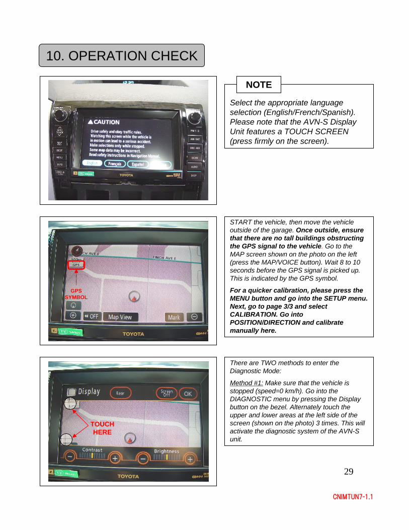
Select the appropriate language selection (English/French/Spanish). Please note that the AVN-S Display Unit features a TOUCH SCREEN (press firmly on the screen).
NOTE
START the vehicle, then move the vehicle outside of the garage. Once outside, ensure that there are no tall buildings obstructing the GPS signal to the vehicle. Go to the MAP screen shown on the photo on the left (press the MAP/VOICE button). Wait 8 to 10 seconds before the GPS signal is picked up. This is indicated by the GPS symbol.
For a quicker calibration, please press the MENU button and go into the SETUP menu. Next, go to page 3/3 and select CALIBRATION. Go into POSITION/DIRECTION and calibrate manually here.
There are TWO methods to enter the Diagnostic Mode:
Method #1: Make sure that the vehicle is stopped (speed=0 km/h). Go into the DIAGNOSTIC menu by pressing the Display button on the bezel. Alternately touch the upper and lower areas at the left side of the screen (shown on the photo) 3 times. This will activate the diagnostic system of the AVN-S unit.
TOUCH TOUCH HEREHERE
GPS GPS SYMBOLSYMBOL
10. OPERATION CHECK
30
CNIMTUN7-1.1
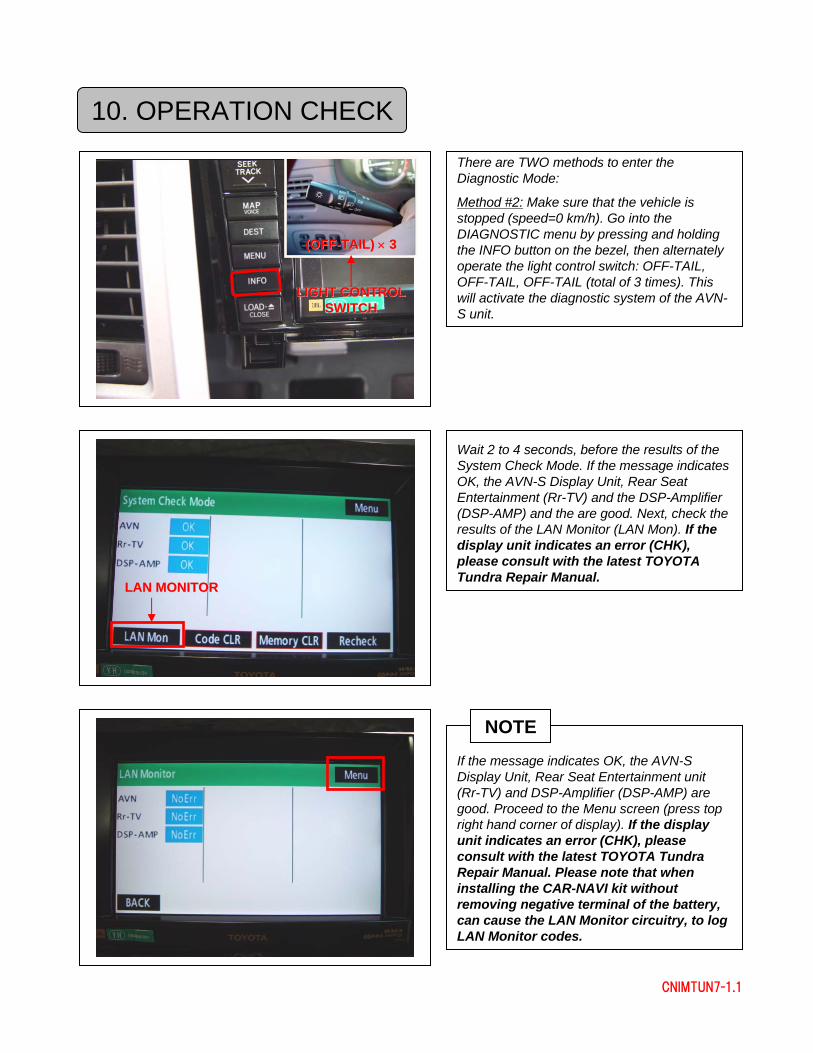
Wait 2 to 4 seconds, before the results of the System Check Mode. If the message indicates OK, the AVN-S Display Unit, Rear Seat Entertainment (Rr-TV) and the DSP-Amplifier (DSP-AMP) and the are good. Next, check the results of the LAN Monitor (LAN Mon). If the display unit indicates an error (CHK), please consult with the latest TOYOTA Tundra Repair Manual.
There are TWO methods to enter the Diagnostic Mode:
Method #2: Make sure that the vehicle is stopped (speed=0 km/h). Go into the DIAGNOSTIC menu by pressing and holding the INFO button on the bezel, then alternately operate the light control switch: OFF-TAIL, OFF-TAIL, OFF-TAIL (total of 3 times). This will activate the diagnostic system of the AVN-S unit.
LIGHT CONTROL LIGHT CONTROL SWITCHSWITCH
LAN MONITORLAN MONITOR
If the message indicates OK, the AVN-S Display Unit, Rear Seat Entertainment unit (Rr-TV) and DSP-Amplifier (DSP-AMP) are good. Proceed to the Menu screen (press top right hand corner of display). If the display unit indicates an error (CHK), pleaseconsult with the latest TOYOTA Tundra Repair Manual. Please note that when installing the CAR-NAVI kit without removing negative terminal of the battery, can cause the LAN Monitor circuitry, to log LAN Monitor codes.
NOTE
10. OPERATION CHECK
(OFF(OFF--TAIL) TAIL) ×× 33
31
CNIMTUN7-1.1
1
2
3
4
1
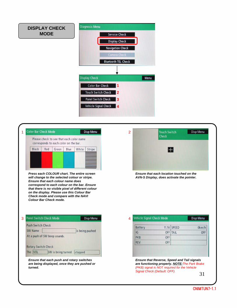
Press each COLOUR chart. The entire screen will change to the selected colour or stripe. Ensure that each colour name does correspond to each colour on the bar. Ensure that there is no visible pixel of different colour on the display. Please use this Colour Bar Check mode and compare with the NAVI Colour Bar Check mode.
2
Ensure that each location touched on the AVN-S Display, does activate the pointer.
3
Ensure that each push and rotary switches are being displayed, once they are pushed or turned.
4
Ensure that Reverse, Speed and Tail signals are functioning properly. NOTE:The Park Brake (PKB) signal is NOT required for the Vehicle Signal Check (Default: OFF).
DISPLAY CHECK MODE
32
CNIMTUN7-1.1
1
2
3
4
1
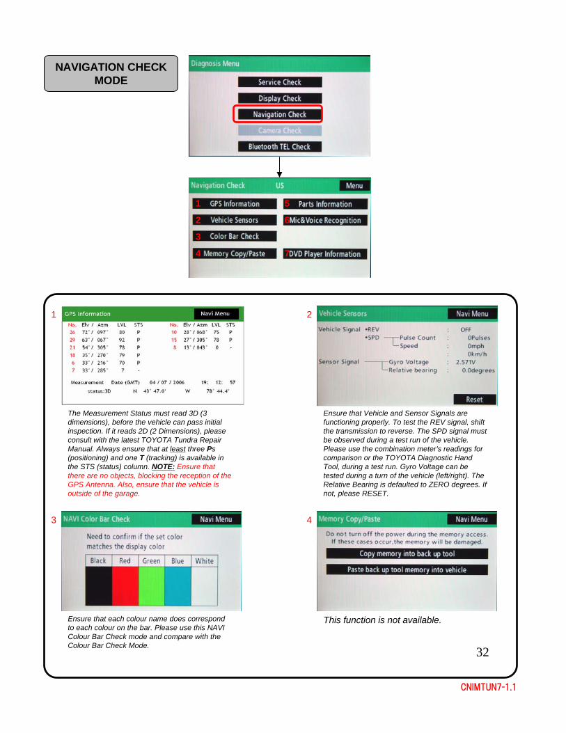
The Measurement Status must read 3D (3 dimensions), before the vehicle can pass initial inspection. If it reads 2D (2 Dimensions), please consult with the latest TOYOTA Tundra Repair Manual. Always ensure that at least three Ps (positioning) and one T (tracking) is available in the STS (status) column. NOTE: Ensure that there are no objects, blocking the reception of the GPS Antenna. Also, ensure that the vehicle is outside of the garage.
2
Ensure that Vehicle and Sensor Signals are functioning properly. To test the REV signal, shift the transmission to reverse. The SPD signal must be observed during a test run of the vehicle. Please use the combination meter’s readings for comparison or the TOYOTA Diagnostic Hand Tool, during a test run. Gyro Voltage can be tested during a turn of the vehicle (left/right). The Relative Bearing is defaulted to ZERO degrees. If not, please RESET.
3 4
This function is not available.
NAVIGATION CHECK MODE
6
5
Ensure that each colour name does correspond to each colour on the bar. Please use this NAVI Colour Bar Check mode and compare with the Colour Bar Check Mode.
7
33
CNIMTUN7-1.1
5
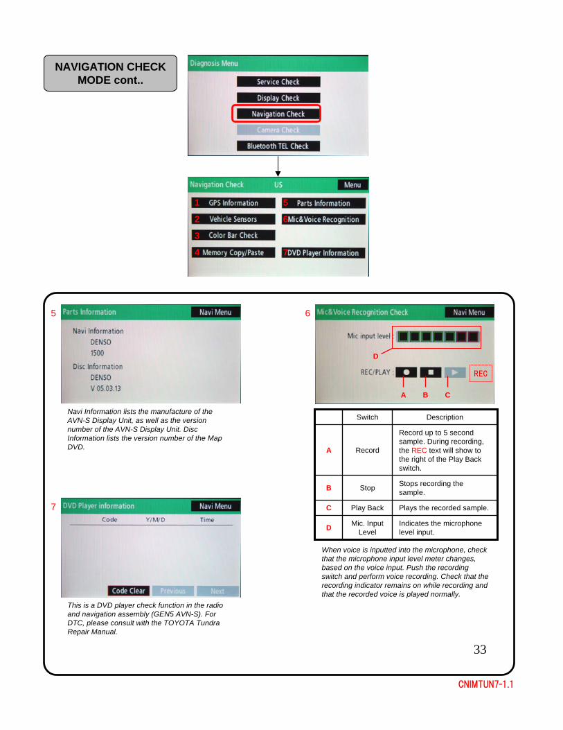
Navi Information lists the manufacture of the AVN-S Display Unit, as well as the version number of the AVN-S Display Unit. Disc Information lists the version number of the Map DVD.
6
When voice is inputted into the microphone, check that the microphone input level meter changes, based on the voice input. Push the recording switch and perform voice recording. Check that the recording indicator remains on while recording and that the recorded voice is played normally.
NAVIGATION CHECK MODE cont..
1
2
3
4
6
5
7
Indicates the microphone level input.
Mic. Input LevelD
Plays the recorded sample.Play BackC
Stops recording the sample.StopB
Record up to 5 second sample. During recording, the REC text will show to the right of the Play Back switch.
RecordA
DescriptionSwitch
A B C
REC
D
7
This is a DVD player check function in the radio and navigation assembly (GEN5 AVN-S). For DTC, please consult with the TOYOTA Tundra Repair Manual.
34
CNIMTUN7-1.1
1
2
1
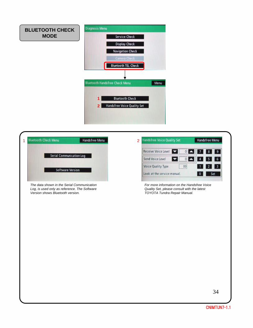
The data shown in the Serial Communication Log, is used only as reference. The Software Version shows Bluetooth version.
2
For more information on the Handsfree Voice Quality Set, please consult with the latest TOYOTA Tundra Repair Manual.
BLUETOOTH CHECK MODE

35
CNIMTUN7-1.1
After the Talk Switch has been pressed, a voice command will ask the user to say a command, after the beep. Please say “HELP”. This will list useful voice recognition commands. Please ensure that you sit back and talk clearly to the MIC, located above of the Personal Light Assembly. DO NOT TALK DIRECTLY INTO THE MIC! Conduct more testing by speaking other listed voice commands, in the HELP menu.
10. OPERATION CHECK: VOICE RECOGNITION
Press the Talk Switch, to initiate the Voice Recognition function.
If the system could not detect your voice command, please ensure that you talk clearly to the MIC. Also, ensure that all connection have been made to the back of the AVN-S unit. Ensure that the interior cabin noise is reduced to minimum. For your reference, please visit the Diagnostic Mode and re-check the Mic & Voice Recognition Check.
TALK TALK SWITCHSWITCH
NOTE
36
CNIMTUN7-1.1
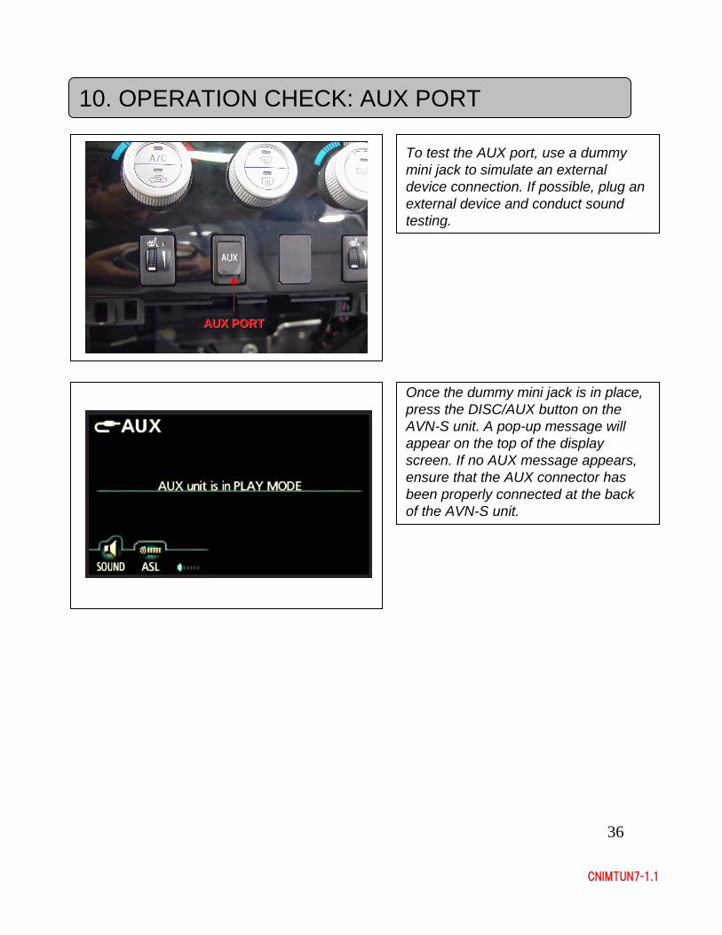
Once the dummy mini jack is in place, press the DISC/AUX button on the AVN-S unit. A pop-up message will appear on the top of the display screen. If no AUX message appears, ensure that the AUX connector has been properly connected at the back of the AVN-S unit.
10. OPERATION CHECK: AUX PORT
To test the AUX port, use a dummy mini jack to simulate an external device connection. If possible, plug an external device and conduct sound testing.
AUX PORTAUX PORT
37
CNIMTUN7-1.1
11. RE-INSTALLATION
For the RE-INSTALLATION section, please follow the DISASSEMBLY section in reverse order. While re-installing original parts, ensure that there is no biting into the vehicle harness, and damage to the original parts.
CAUTION
BATTERYBATTERY
NEGATIVE NEGATIVE TERMINALTERMINAL
FRO
NT
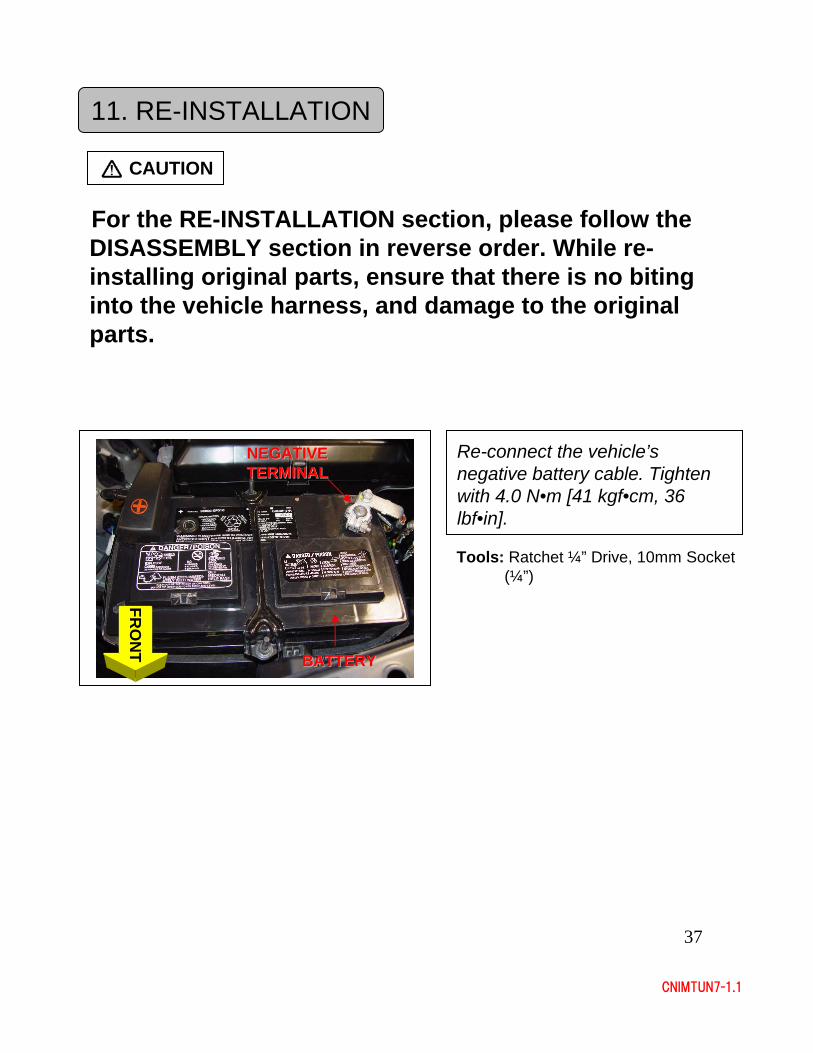
Re-connect the vehicle’s negative battery cable. Tighten with 4.0 N•m [41 kgf•cm, 36 lbf•in].
Tools: Ratchet ¼” Drive, 10mm Socket (¼”)
38
CNIMTUN7-1.1
12. RE-INITIALIZING
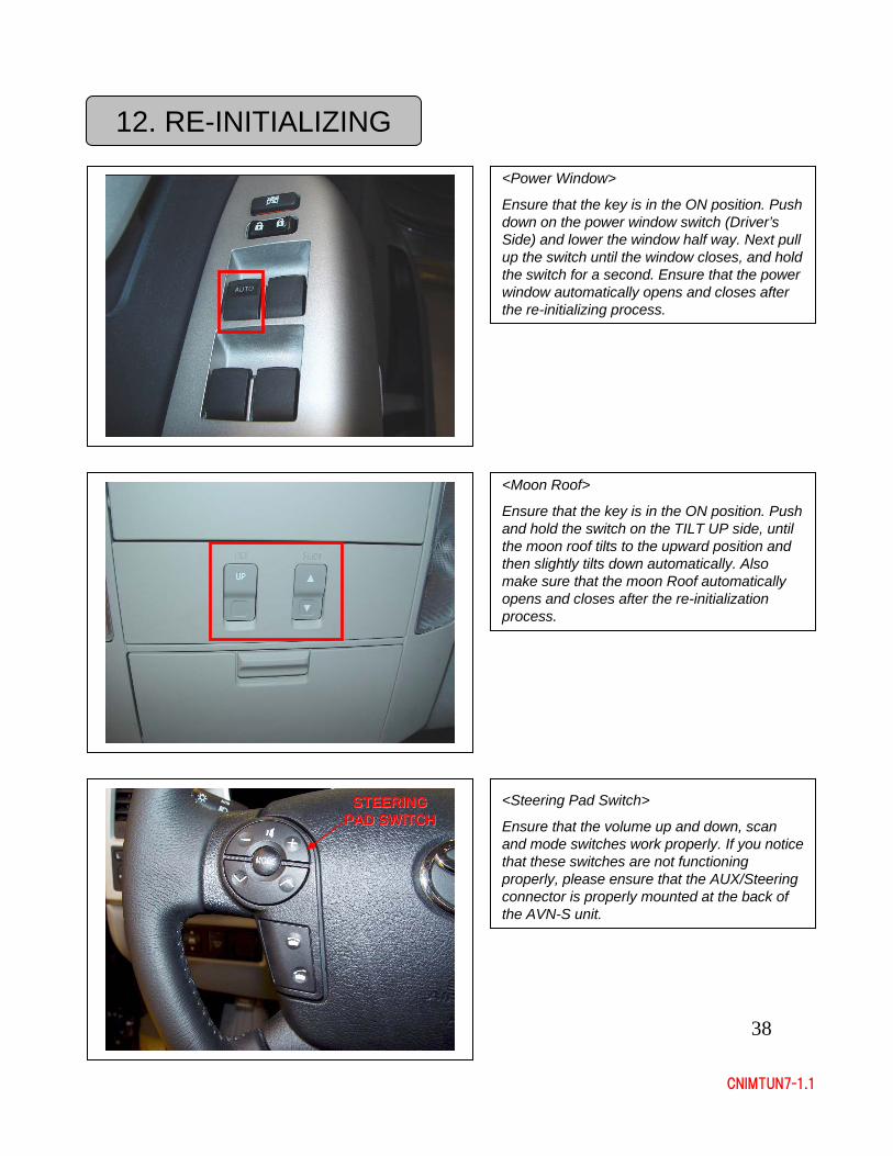
<Power Window>
Ensure that the key is in the ON position. Push down on the power window switch (Driver’s Side) and lower the window half way. Next pull up the switch until the window closes, and hold the switch for a second. Ensure that the power window automatically opens and closes after the re-initializing process.
<Moon Roof>
Ensure that the key is in the ON position. Push and hold the switch on the TILT UP side, until the moon roof tilts to the upward position and then slightly tilts down automatically. Also make sure that the moon Roof automatically opens and closes after the re-initialization process.
<Steering Pad Switch>
Ensure that the volume up and down, scan and mode switches work properly. If you notice that these switches are not functioning properly, please ensure that the AUX/Steering connector is properly mounted at the back of the AVN-S unit.
STEERING STEERING PAD SWITCHPAD SWITCH
39
CNIMTUN7-1.1
12. RE-INITIALIZING
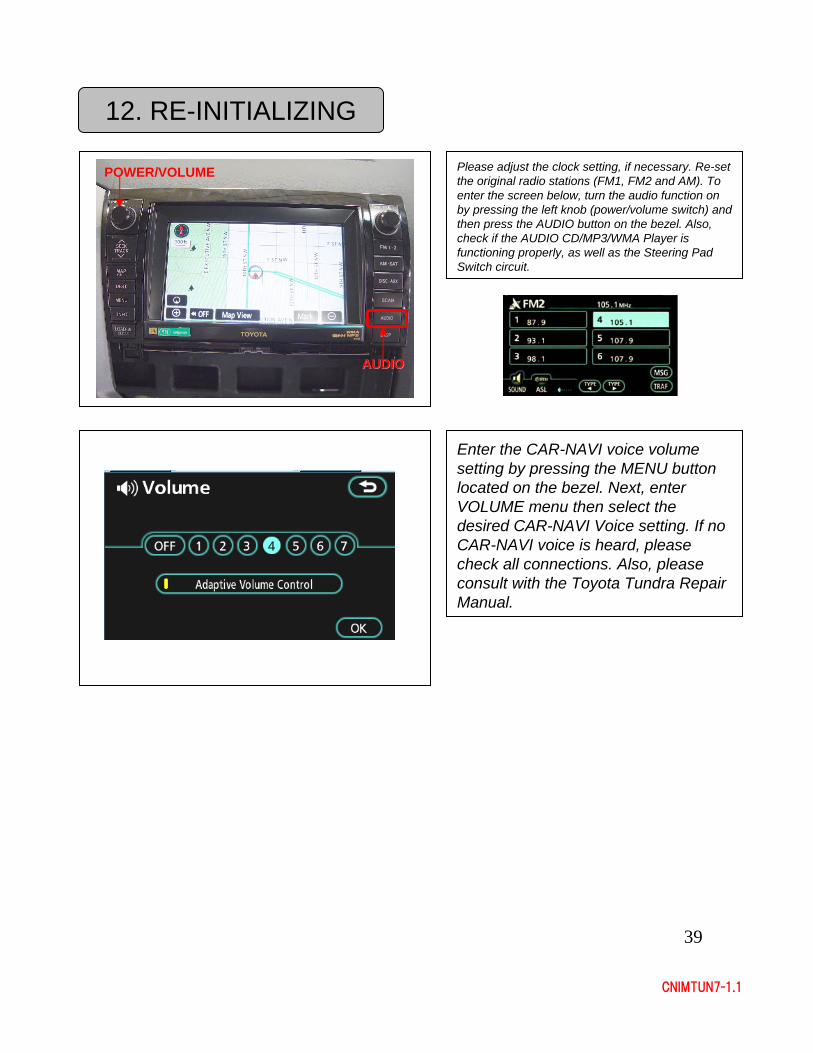
Enter the CAR-NAVI voice volume setting by pressing the MENU button located on the bezel. Next, enter VOLUME menu then select the desired CAR-NAVI Voice setting. If no CAR-NAVI voice is heard, please check all connections. Also, please consult with the Toyota Tundra Repair Manual.
Please adjust the clock setting, if necessary. Re-set the original radio stations (FM1, FM2 and AM). To enter the screen below, turn the audio function on by pressing the left knob (power/volume switch) and then press the AUDIO button on the bezel. Also, check if the AUDIO CD/MP3/WMA Player is functioning properly, as well as the Steering Pad Switch circuit.
AUDIOAUDIO
POWER/VOLUMEPOWER/VOLUME
CNIMTUN7-1.1
Published: February 2007
[Duplication prohibited without permission]
SUPERVISION: Toyota Canada Inc.
EDITING: DENSO Manufacturing Canada, Inc.