Embed Size (px)
Citation preview
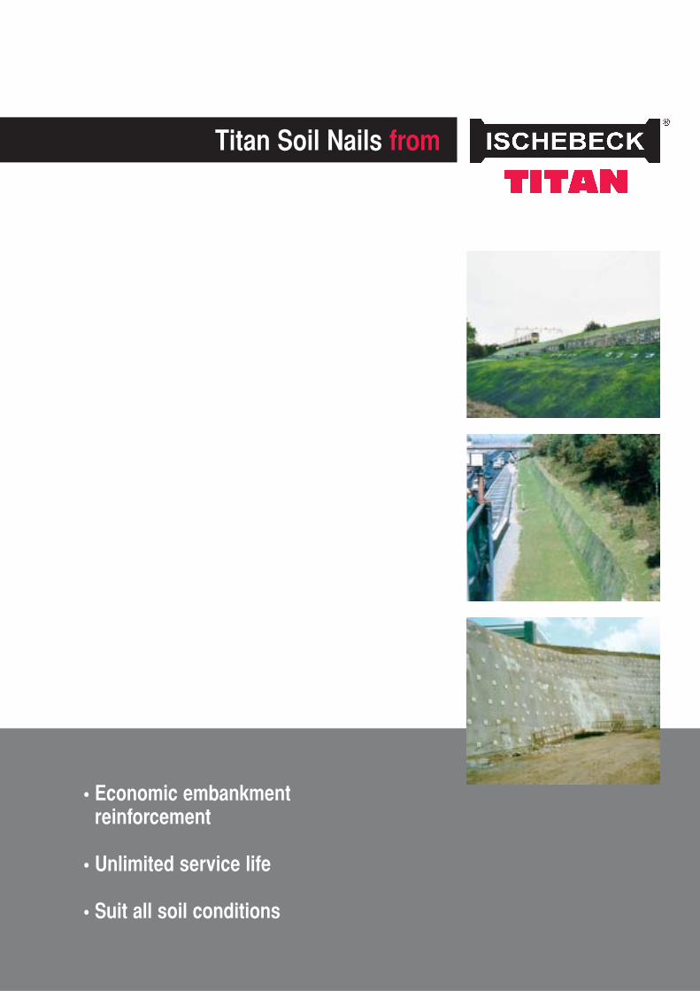
Titan Soil Nails from
• Economic embankmentreinforcement
• Unlimited service life
• Suit all soil conditions

Titan Soil Nails from
Soil nailing is an efficient, effective andeconomical method of earth reinforcement,which allows a controlled improvement of thenatural stability of the soil.
Titan soil nails provide friction, shear andtension strength in loose materials,combining all into a new monolithic structure.
Soil nailing consists of 3 basic elements:
1. Existing soils or weathered rock.
2. Titan rotary grouted, self drilling soil nails.
3. Surface treatment with reinforcedshotcrete, geotextile mesh or tensionedwire nets on slopes to 70 degrees.
Titan soil nails are installed by simultaneousdrilling and grouting, which enhances thediameter of the grout body and maximisesshear value at the grout/ground interface.
Correct design of the nail positioning gridacross an embankment and soil nail lengths,results in a monolithic structure capable ofsupporting required loads.
Advantages of soil nailing
• Installation is practically free from vibration.
• Drill rigs can install soil nails at all angles.
• As there is no requirement to case line the drillhole, most drill rigs installing Titan soil nailsare smaller and can cope well with slopes andconfined spaces.
• Soil nailing offers the opportunity to produce anenvironmentally friendly but technically safe“green wall” solution, often less expensive thantraditional back anchored retaining walls.

spherical collar nut
wedge disc
load plate
active zone
soil areaimprovedby grout
coupling
spacer
slip plane
passive zone
TITANhollow soil nail
flushing throughhollow bar
coupling
spacer
grout cover > 25mm
sacrificial drill bit
The Advantages:• Accommodate unexpected changes in load or ground conditions
• Load range up to 150kN SWL installed by hand-held rock drills
• Can substitute sheet piled walls for cut and cover tunnels
• Stronger and cheaper than solid GRP soil nails
• Viable alternative to concrete retaining walls
• Installed at twice the rate of solid bars
• Unaffected by stray electrical currents
• Suitable for all ground conditions
• Self-drilling, caseless installation
• Services all load cases
• Unlimited service life
The Ischebeck Titan Soil Nailis a value-added product
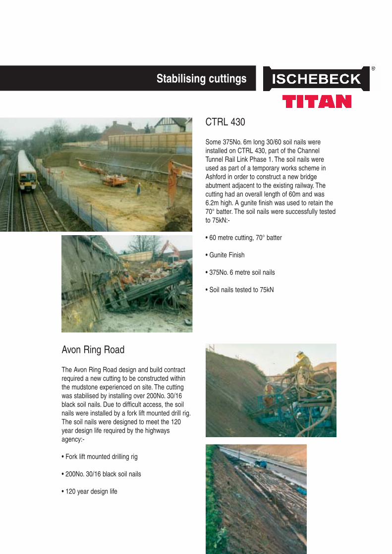
Stabilising cuttings
Avon Ring Road
The Avon Ring Road design and build contractrequired a new cutting to be constructed withinthe mudstone experienced on site. The cuttingwas stabilised by installing over 200No. 30/16black soil nails. Due to difficult access, the soilnails were installed by a fork lift mounted drill rig.The soil nails were designed to meet the 120year design life required by the highwaysagency:-
• Fork lift mounted drilling rig
• 200No. 30/16 black soil nails
• 120 year design life
CTRL 430
Some 375No. 6m long 30/60 soil nails wereinstalled on CTRL 430, part of the ChannelTunnel Rail Link Phase 1. The soil nails wereused as part of a temporary works scheme inAshford in order to construct a new bridgeabutment adjacent to the existing railway. Thecutting had an overall length of 60m and was6.2m high. A gunite finish was used to retain the70° batter. The soil nails were successfully testedto 75kN:-
• 60 metre cutting, 70° batter
• Gunite Finish
• 375No. 6 metre soil nails
• Soil nails tested to 75kN
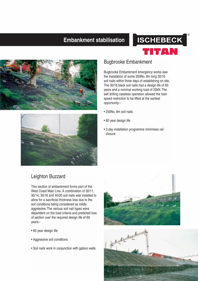
Leighton Buzzard
This section of embankment forms part of theWest Coast Main Line. A combination of 30/11,30/14, 30/16 and 40/20 soil nails was installed toallow for a sacrificial thickness loss due to thesoil conditions being considered as mildlyaggressive. The various soil nail types weredependent on the load criteria and predicted lossof section over the required design life of 60years:-
• 60 year design life
• Aggressive soil conditions
• Soil nails work in conjunction with gabion walls
Bugbrooke Embankment
Bugbrooke Embankment emergency works sawthe installation of some 250No. 8m long 30/16soil nails within three days of establishing on site.The 30/16 black soil nails had a design life of 60years and a nominal working load of 20kN. Theself drilling caseless operation allowed the trainspeed restriction to be lifted at the earliestopportunity:-
• 250No. 8m soil nails
• 60 year design life
• 3 day installation programme minimises railclosure
Embankment stabilisation
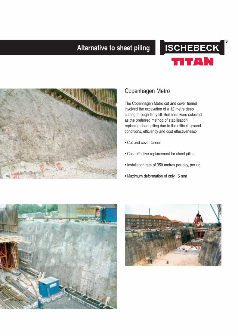
Copenhagen Metro
The Copenhagen Metro cut and cover tunnelinvolved the excavation of a 12 metre deepcutting through flinty till. Soil nails were selectedas the preferred method of stabilisation,replacing sheet piling due to the difficult groundconditions, efficiency and cost effectiveness:-
• Cut and cover tunnel
• Cost effective replacement for sheet piling
• Installation rate of 350 metres per day, per rig
• Maximum deformation of only 15 mm
Alternative to sheet piling
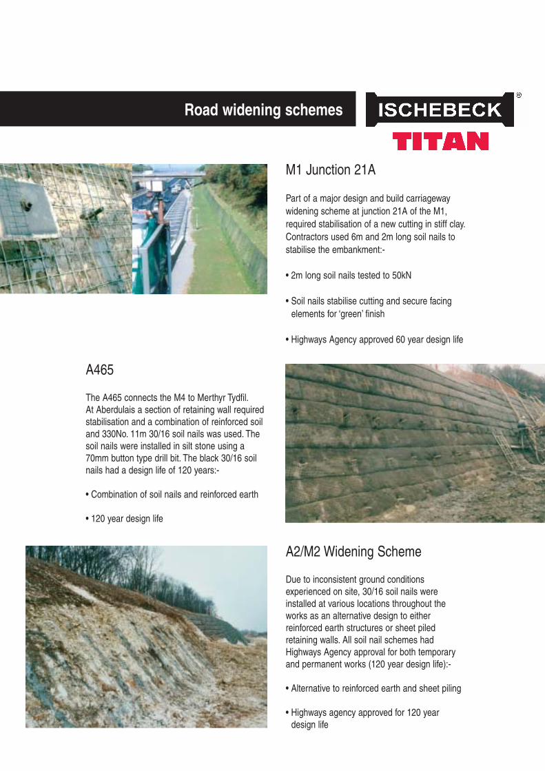
A465
The A465 connects the M4 to Merthyr Tydfil.At Aberdulais a section of retaining wall requiredstabilisation and a combination of reinforced soiland 330No. 11m 30/16 soil nails was used. Thesoil nails were installed in silt stone using a70mm button type drill bit. The black 30/16 soilnails had a design life of 120 years:-
• Combination of soil nails and reinforced earth
• 120 year design life
A2/M2 Widening Scheme
Due to inconsistent ground conditionsexperienced on site, 30/16 soil nails wereinstalled at various locations throughout theworks as an alternative design to eitherreinforced earth structures or sheet piledretaining walls. All soil nail schemes hadHighways Agency approval for both temporaryand permanent works (120 year design life):-
• Alternative to reinforced earth and sheet piling
• Highways agency approved for 120 yeardesign life
M1 Junction 21A
Part of a major design and build carriagewaywidening scheme at junction 21A of the M1,required stabilisation of a new cutting in stiff clay.Contractors used 6m and 2m long soil nails tostabilise the embankment:-
• 2m long soil nails tested to 50kN
• Soil nails stabilise cutting and secure facingelements for ‘green’ finish
• Highways Agency approved 60 year design life
Road widening schemes

Liversedge
Used in conjunction with a 150mm thick gabionwall filled with Yorkshire stone, soil nails providedthe viable alternative to ordinary reinforcedconcrete retaining walls and provided a free-draining, aesthetically pleasing finish, as well as maximising the floor area available fordevelopment:-
• Soil nails as an alternative to reinforcedconcrete retaining wall
• 800No. 30/16 soil nails installed as excavationprogressed
• 120 year design life
• 150mm thick gabion mattress
• Factory floor space was doubled
Creating space for site development
Ballylumford Power Station
The United Kingdom’s largest soil nail andshotcrete retaining wall was used to double thesize of this electricity generating plant inNorthern Ireland. After cutting back a naturalslope comprising clay, large basalt bolders andcobbles, contractors exploited the outstandingperformance characteristics of Titan soil nails todrill into these difficult ground conditions andstabilise the embankment
• 1400No. soil nails of between 9m and 18m
• 70mm carbide bits
• 120 year design life
Titan self drilling, self groutinghollow soil nails to DIN 21521
The concept of soil nails can be compared totimber technology whereby two planks of woodare joined by nails. The nails develop tensionforces, preventing the planks being pulled apart.The nails resist shear forces between the twoplanks, preventing them from sliding.
To guarantee the maximum shear value at thegrout/ground interface the Titan soil nail isinstalled by simultaneous drilling and grouting.Thereby enhancing the diameter of the groutbody.
The dynamic rotary pressure grouting processpenetrates into loose material at the grout/groundinterface, dramatically increasing skin friction.This produces an enhanced grout body, giving apull-out value equivalent to twice the drill bitdiameter in non-cohesive soils.
Bottom up pressure grouting through the hollowTitan soil nail, fills all fissures and voids on theway to the surface. The rotary percussive drillingaction improves the grout strength similar to aconcrete vibrating poker.
All the benefits above combine to produce themost effective method of mobilising the maximumstrength available in the ground.
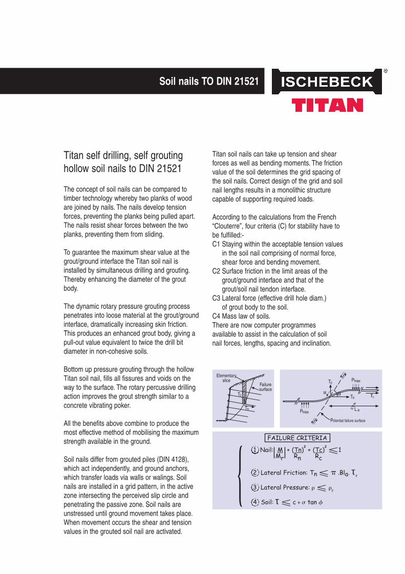
Soil nails differ from grouted piles (DIN 4128),which act independently, and ground anchors,which transfer loads via walls or walings. Soilnails are installed in a grid pattern, in the activezone intersecting the perceived slip circle andpenetrating the passive zone. Soil nails areunstressed until ground movement takes place.When movement occurs the shear and tensionvalues in the grouted soil nail are activated.
Elementaryslice
Failuresurface
Tc
Tn
Tc
TnM
L aPmax
Pmax
Potential failure surface
α τ I
Titan soil nails can take up tension and shearforces as well as bending moments. The frictionvalue of the soil determines the grid spacing ofthe soil nails. Correct design of the grid and soilnail lengths results in a monolithic structurecapable of supporting required loads.
According to the calculations from the French“Clouterre”, four criteria (C) for stability have tobe fulfilled:-C1 Staying within the acceptable tension values
in the soil nail comprising of normal force,shear force and bending movement.
C2 Surface friction in the limit areas of thegrout/ground interface and that of thegrout/soil nail tendon interface.
C3 Lateral force (effective drill hole diam.)of grout body to the soil.
C4 Mass law of soils.There are now computer programmesavailable to assist in the calculation of soilnail forces, lengths, spacing and inclination.
Soil nails TO DIN 21521
FAILURE CRITERIA
1 Nail: M + (Tn)2 + (Tc)2 �1Mr Rn Rc
2 Lateral Friction: Tn � � .Bla. τ�
3 Lateral Pressure: � � ��
4 Soil: τ � c + � tan �
{
Calculation
In the United Kingdom, soil nailing with Titan soilnails is approved by the Highways Agency,Railtrack, Ministry of Defence, the EnvironmentAgency, British Waterways and many of the topconsulting engineering practices. In GermanyTitan soil nails correspond to DIN 21521.
In all calculations there is an active zone, whichmay come loose by pre-deformation and apassive zone, which is static. Both zones areseparated by a slip plane, which is considered forcalculation as curved or straight.
Very often the slip plane is due to nature, e.g.water containing boundary layers or back filledslopes.
length of nails 0.5 to 0.7 x wall heightbut not less than 6.0 m
capacity of nails 50 to 250 kN/m2
density of nails 0.5 to 2.0 per m2
amount of reinforcement 1.5 to 6.0 kg/m3
nail forces 50 to 100 kN (in specialapplications up to 300 kN)
inclination of nails 0 to 30 degrees
deformation of nailed walls 1.50% x wall height
There are 3 general rules forthe calculation and installationof soil nails:-
1. Soil nails must penetrate beyond the slip planeinto the passive zone typically for 4-5 metres.
2. The spacing of the soil nails, horizontally andvertically, must be directly related to thestrength of the soil. Extra soil nails should beinstalled at the edge of any surface beingstabilised.
3. Soil nailing should commence immediatelyafter excavation. Any delay increases thechance of the unrestrained ground relaxing.Early soil nail installation ensures themaximum holding power.
Calculation & installation
With FE-calculations, nails or bolts are designedby changing the cohesion or by inserting atension element (truss) in the area to benailed/bolted. The expansion stiffness of thetension element (truss) is derived from nail/bolttests (0.5 m long). For three-dimensional FE-calculations the modelling of the cohesion showssuitable results. For two-dimensional FE-calculations the modelling of the expansionstiffness is more suitable.
As nails and bolts are only activated bydeformation, it is assumed that prior to anymovement of rock/soil mass only the selfcohesion of the mass is active. When thestrength of the soil is exceeded, the frictionchanges with increasing plastic elongation for thesum: Cremainder (which is the cohesion remaining insoil or rock) plus the cohesive effect from Cnail.The cohesive effect depends on the quality of thesoil and the mechanical strength of the nail/boltitself. The nails/bolts are calculated in a simpleway based on the thesis of Wullschlager(“A composite material model for the systemanchoring” published by the institute of SoilMechanic and Rock Mechanic of the UniversityFridericana in Karlsruhe/Germany,paper no. 1 1 2, 1088).
This approach is valid for loose materials butover designed for sound rock.
Finite element calculation
Numeric modelling of TITAN soilnails and rock bolts for the finiteelement (FE) calculation
Cnail = 1+ sin�
•P2cos�
P = F
a • b
P = density of nailF (Tn) = nail forcea, b = designed grid
pattern of nails� = angle of frictionC = cohesion between
2 finite elementsCremainder = remaining cohesion
of soil/rock
conservative calculation calculating including remaining cohesion of soil/rock
loose soil loose soilCnail = 39 kN/m2 = >Cremainder + Cnail = 39.0 kN/m2
highly weathered rock (V4 - V5) highly weathered rock (V4 - V5)Cnail = 43 kN/m2 = >Cremainder + Cnail = 55.5 kN/m2
moderately weathered rock (V2 - V3) moderately weathered rock (V2 - V3)Cnail = 51 kN/m2 = >Cremainder + Cnail = 81.0 kN/m2

Ischebeck Titan Group
Founded in Germany over 120 years ago Ischebeck isrenowned internationally for it’s aluminium formwork andfalse work systems, trench support systems and groundengineering products.
Ischebeck NZ Ltd
The company operates from headquarters centrally located in Auckland.
Product Availability
Substantial stocks of equipment are available ex-stock fromthe company’s strategically located 4-acre distribution site,with most items available nationwide on a 48-hour delivery.Products are available for both hire and outright purchase.
Technical Support
We will participate in concept stage development. Providinginput on applications, production rates, budget design andcostings. Active for on site support, particularly for newusers. We can provide guidance on industry specialeuropean and national standards.
Imported and Distributed in New Zealand by:
ISCHEBECK NZ Ltd1 Wharangi StOnehunga 1061Auckland
PO Box 13613Onehunga 1643Auckland
T 09 6341973F 09 6345176E [email protected]