Embed Size (px)
Citation preview
Tire Conditions Guidefor Passenger Cars and Light Trucks
Tire Reference Guide for Service Advisors
and Technicians
FTCG 1.0 12/01/2006
Introduction / Customer Interface ........................................................................................1
Normal vs. Abnormal Tire Wear ............................................................................................2
Glossary of Tire Terminology ................................................................................................3
Proper Tire & Wheel Inspection ............................................................................................4
Separation Inspection Guidelines ........................................................................................5
Vibration Diagnosis ..............................................................................................................6
Tire Conditions
Non-Warrantable Tread Concerns ...................................................................................7
Warrantable Tread Concerns ..........................................................................................10
Non-Warrantable Sidewall Concerns .............................................................................14
Warrantable Sidewall Concerns .....................................................................................17
Non-Warrantable Wear Concerns...................................................................................23
Other Non-Warrantable Tire Concerns ...........................................................................26
Other Warrantable Tire Concerns ...................................................................................27
Repairs – Warranty Information ...........................................................................................28
Repairs – Proper repair / Improper repair ............................................................................29
References ..........................................................................................................................36
Content Page
Table of Contents
1
Introduction
The purpose of this guide is to provide all Ford, Mercury and Lincoln Dealers with the necessary information to determine if a specific tire condition is warrantable or not.
Effective with model year 2001 vehicles, Ford Motor Company warrants the original equipment tires for all passenger cars and light trucks (up to and including F-550 series). Refer to the Warranty & Policy Manual for the specific coverage and limitations to this warranty. For warranty claim preparation instructions refer to the ACESII User Manual.
The following pages are arranged by the type of condition experienced with the tire. Each condition is defined along with the available Ford Tire Condition Code and provides examples of warrantable versus non-warrantable tire conditions.
This guide has been developed for Ford, Mercury and Lincoln Dealers to assist them with administering the Ford Tire Warranty. This guide is not intended as an application for warrantable concerns for tires filed directly with the Tire Manufacturers.
CustomerInterfaceMost tire concerns seen by dealers are not covered under warranty. The majority of tires replaced in service are replaced due to road hazards or lack of proper tire maintenance. Below are some general guidelines to use when dealing with customers experiencing a problem with their tires.
LISTEN – always listen to what your customers say. When customers have been inconvenienced, they want someone to listen to their problem. It is to your advantage to obtain all of the details in order to help the technician determine the root cause of the tire failure.
OBSERVE – make sure that you observe things like scuff marks on the tires or scratches/dents around the wheel wells indicating a tendency of the driver’s habits.
EXPLAIN – Ford’s Tire warranty coverage to ensure that customers understand what the warranty does and does not cover. Explain to your customers that regardless of the nature of the tire condition, you cannot assure them that it is covered under warranty until it has been evaluated.
MANAGE – based upon the customer’s explanation and the visual evidence much can be assumed, but it is imperative to manage a customer’s expectations carefully. Many tire conditions require a thorough evaluation by a trained tire specialist to properly determine “root cause” of the failure.
2
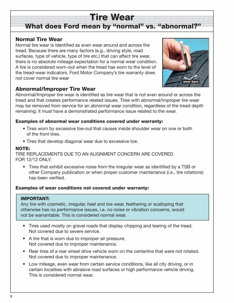
TireWearWhatdoesFordmeanby“normal”vs.“abnormal?”
NormalTireWearNormal tire wear is identified as even wear around and across the tread. Because there are many factors (e.g., driving style, road surfaces, type of vehicle, type of tire etc.) that can affect tire wear, there is no absolute mileage expectation for a normal wear condition. A tire is considered worn-out when the tread has worn to the level of the tread-wear indicators. Ford Motor Company’s tire warranty does not cover normal tire wear
Abnormal/ImproperTireWearAbnormal/Improper tire wear is identified as tire wear that is not even around or across the tread and that creates performance related issues. Tires with abnormal/improper tire wear may be removed from service for an abnormal wear condition, regardless of the tread depth remaining; it must have a demonstrated performance issue related to the wear.
Examplesofabnormalwearconditionscoveredunderwarranty:
• Tires worn by excessive toe-out that causes inside shoulder wear on one or both of the front tires.
• Tires that develop diagonal wear due to excessive toe.
NOTE:TIRE REPLACEMENTS DUE TO AN ALIGNMENT CONCERN ARE COVERED FOR 12/12 ONLY.
• Tires that exhibit excessive noise from the irregular wear as identified by a TSB or other Company publication or when proper customer maintenance (i.e., tire rotations) has been verified.
Examplesofwearconditionsnotcoveredunderwarranty:
IMPORTANT: Any tire with cosmetic, irregular, heel and toe wear, feathering or scalloping that otherwise has no performance issues, i.e. no noise or vibration concerns, would not be warrantable. This is considered normal wear.
• Tires used mostly on gravel roads that display chipping and tearing of the tread. Not covered due to severe service.
• A tire that is worn due to improper air pressure. Not covered due to improper maintenance.
• Rear tires of a rear wheel drive vehicle worn on the centerline that were not rotated. Not covered due to improper maintenance.
• Low mileage, even wear from certain service conditions, like all city driving, or in certain localities with abrasive road surfaces or high performance vehicle driving. This is considered normal wear.
wearbars
�
TireLabel A label showing the OE (original equipment) tire sizes, recommended inflation pressure and the maximum weight the vehicle can carry. Located on the B-Pillar or the edge of the driver’s door.
TireIdentificationNumber(TIN) also referred to as DOT code– A number on the sidewall of each tire providing information about the tire brand and manufacturing plant, tire size and date of manufacture.
InflationPressure A measure of the amount of air in a tire.
Standardload A class of P-metric or Metric tires designed to carry a maximum load at 35 psi [37 psi (2.5 bar) for Metric tires]. Increasing the inflation pressure beyond this pressure will not increase the tire’s load carrying capability.
Extraload A class of P-metric or Metric tires designed to carry a heavier maximum load at 41 psi [43 psi (2.9 bar) for Metric tires]. Increasing the inflation pressure beyond this pressure will not increase the tire’s load carrying capability.
kPa Kilopascal, a metric unit of air pressure.
PSIPounds per square inch, a standard unit of air pressure.
Coldinflationpressure The tire pressure when the vehicle has been stationary and out of direct sunlight for an hour or more and prior to the vehicle being driven for 1 mile (1.6 km).
Recommendedinflationpressure The cold inflation pressure found on the Safety Compliance Certification Label or Tire Label located on the B-Pillar or the edge of the driver’s door.
B-Pillar The structural member at the side of the vehicle behind the front door.
Beadareaofthetire Area of the tire next to the rim.
Sidewallofthetire Area between the bead area and the tread.
Treadareaofthetire Area of the perimeter of the tire that contacts the road when mounted on the vehicle.
Rim The metal support (wheel) for a tire or a tire and tube assembly upon which the tire beads are seated.
�
Proper Tire and Wheel Inspection
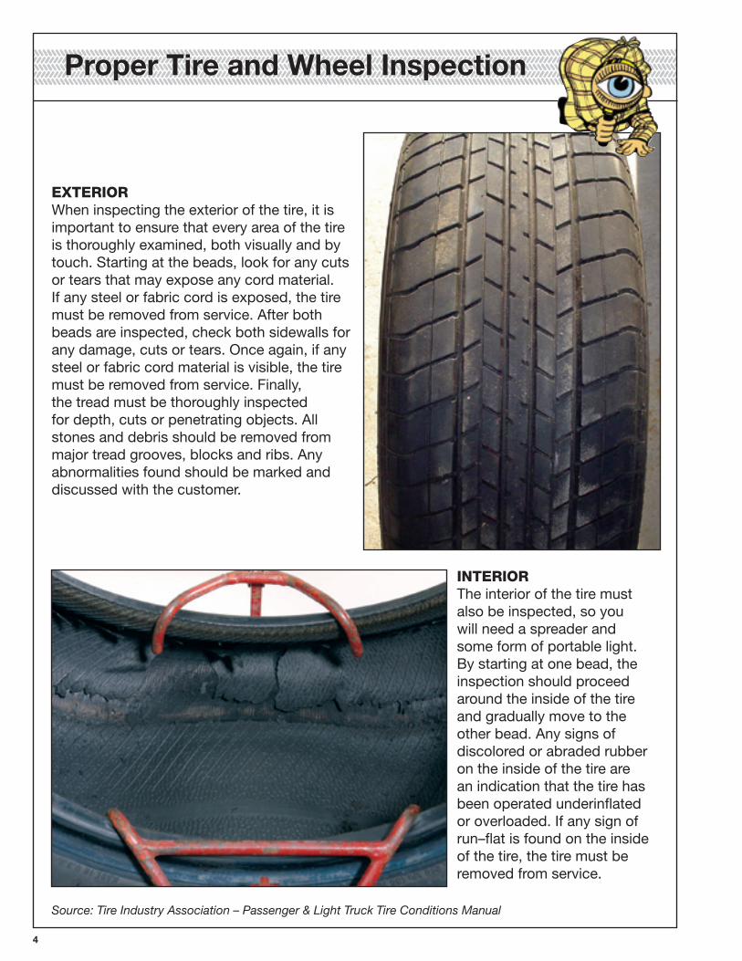
EXTERIORWhen inspecting the exterior of the tire, it is important to ensure that every area of the tire is thoroughly examined, both visually and by touch. Starting at the beads, look for any cuts or tears that may expose any cord material. If any steel or fabric cord is exposed, the tire must be removed from service. After both beads are inspected, check both sidewalls for any damage, cuts or tears. Once again, if any steel or fabric cord material is visible, the tire must be removed from service. Finally, the tread must be thoroughly inspected for depth, cuts or penetrating objects. All stones and debris should be removed from major tread grooves, blocks and ribs. Any abnormalities found should be marked and discussed with the customer.
INTERIOR The interior of the tire must also be inspected, so you will need a spreader and some form of portable light. By starting at one bead, the inspection should proceed around the inside of the tire and gradually move to the other bead. Any signs of discolored or abraded rubber on the inside of the tire are an indication that the tire has been operated underinflated or overloaded. If any sign of run–flat is found on the inside of the tire, the tire must be removed from service.
Source: Tire Industry Association – Passenger & Light Truck Tire Conditions Manual
�
It is widely recognized within the tire industry that tread/belt separations and/or detachments can occur from a wide variety of service conditions such as over deflection (overloading and/or underinflation), unrepaired and improperly repaired punctures or injuries, wear into the belt structure, impact damage, road hazards, mounting damage, high speed operation, vehicle conditions like misalignment, improper storage, and other types of service damage or abuse. Each of these service conditions normally changes the physical condition of the tire or otherwise leaves evidence of the underlying cause of the separation.
Evidence of cause of this condition may include:
• Rim flange impressions and/or abrasions
• Wheel weight impressions and/or abrasions
• Rapid tread wear on both shoulders
• Rubber discoloration
• Deterioration of the inner liner
• Heat discoloration of the inner liner
• Circumferential sidewall scuffing
• Localized tread wear
• Reversion of rubber stock
• Melted body ply cords
Over deflected operation, for example, usually creates a noticeable compression groove in the bead area of the tire. It also may affect the nature of the tire’s tread wear, and in extreme cases, discolor, abrade or even crack various components within the tire.
Penetrations into and/or through the tire can allow contaminants and/or pressurized air into the casing and may lead to separations between components. Any condition which exposes bare cord inside the tire can allow pressurized air into the casing (pressurization of the casing). Any tire may fail in use as a result of previous or current punctures, injuries, impact damage, improper inflation, overloading, improper storage, or other conditions resulting from use or misuse. Road hazard damaged tires from impacts can lead to tread wear damage, tread wear irregularities and internal structural damage such as broken cords and splits in the inner liner. For example, a road hazard damage that causes an inner liner split can lead to pressurization of the casing from air migrating from inside the inner liner into the body structure breaking down vulcanized rubber so as to expose cords and eventual tread separation from the casing or belts.
Source: Tire Industry Association – Passenger & Light Truck Tire Conditions Manual
Separation Inspection Guidelines
6
TIRECONDITIONCODE“TB3”The following procedure should be used if normal diagnostics lead to a potential runout issue. The procedure is intended to assist with the diagnosis of tire/wheel assembly runout and/or force variation issues. To diagnose and correct the concern, refer to the following Service Procedure.
NOTE: FOLLOW THIS PROCEDURE ONLY IF THERE ARE NO SPECIFIC TSBs/SSMs RELEASED FOR THE VEHICLE SYMPTOM BEING EXPERIENCED.
SERVICEPROCEDURE:1. Measure the assembly runout, or R1H Road Force, and mark the magnitude (Road Force
reading if using the Hunter GSP9700; amount of runout if using a dial indicator) and location on the tire. As the assembly is reworked, the value and location on the tire are important.
NOTE: Use runout guidelines for the appropriate vehicle from the available service workshop manual or TSB.
2. If assembly runout (or Road Force) is high, evaluate effect of re–indexing the tire and wheel.
a. Mark the tire at the valve stem. This is to reference the original indexing location. b. Deflate the tire and break down both beads from the wheel. Rotate the tire 180 degrees on the rim, rather than following the Hunter GSP9700 balancer’s routine for indexing. c. Re–inflate the tire to the measurement pressure and measure the assembly runout again. d. Mark this second high spot of runout on the tire.
NOTE: IF THE RUNOUT GOES DOWN SIGNIFICANTLY, THEN THE ORIGINAL TIRE WHEEL ASSEMBLY INDEXING WAS NOT OPTIMIZED OR THE TIRE CHANGED IN SERVICE.
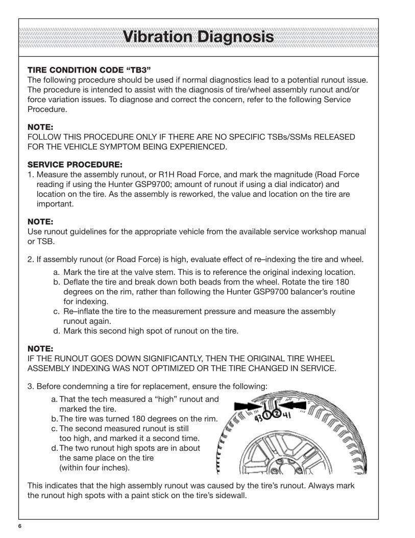
3. Before condemning a tire for replacement, ensure the following:
a. That the tech measured a “high” runout and marked the tire. b. The tire was turned 180 degrees on the rim. c. The second measured runout is still too high, and marked it a second time. d. The two runout high spots are in about the same place on the tire (within four inches).
This indicates that the high assembly runout was caused by the tire’s runout. Always mark the runout high spots with a paint stick on the tire’s sidewall.
Vibration Diagnosis
�
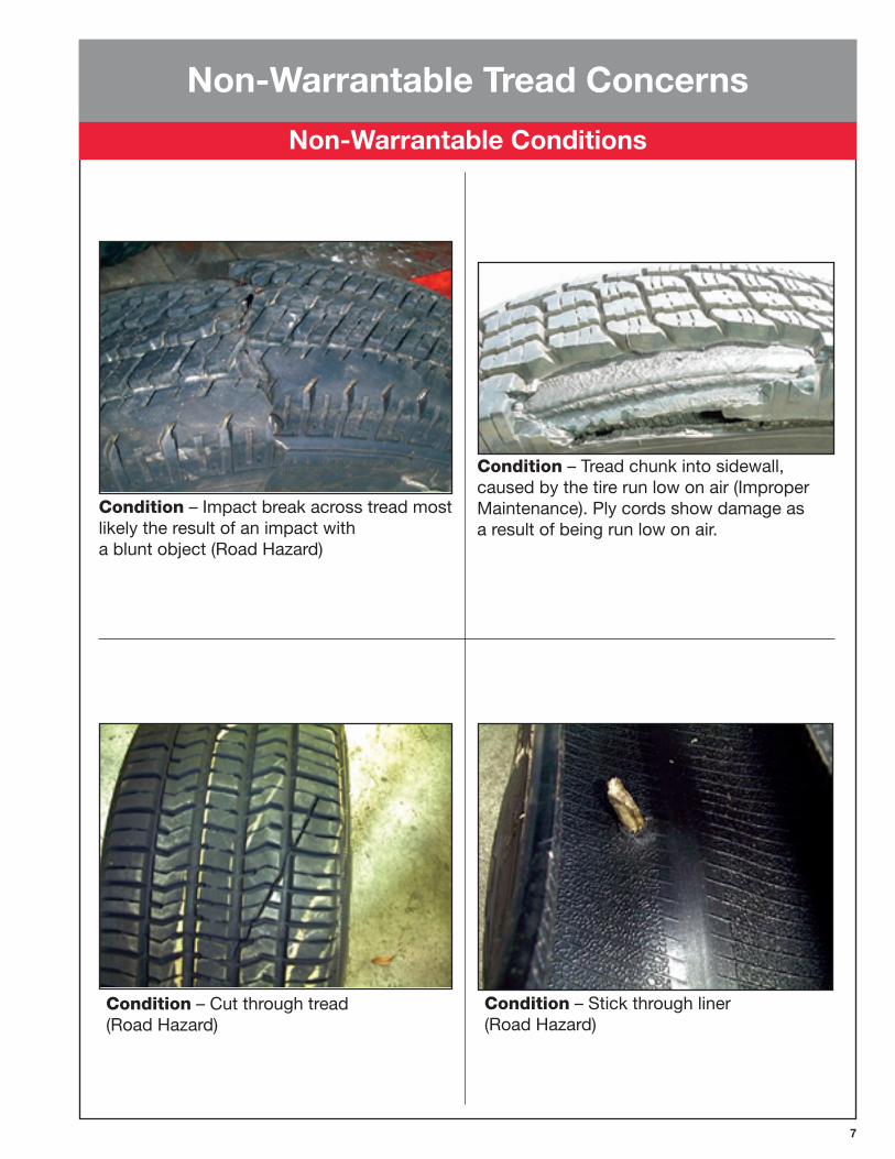
Condition – Cut through tread (Road Hazard)
Condition – Stick through liner (Road Hazard)
Condition – Impact break across tread most likely the result of an impact with a blunt object (Road Hazard)
Condition – Tread chunk into sidewall, caused by the tire run low on air (Improper Maintenance). Ply cords show damage as a result of being run low on air.
Non-Warrantable Tread Concerns
Non-Warrantable Conditions
�
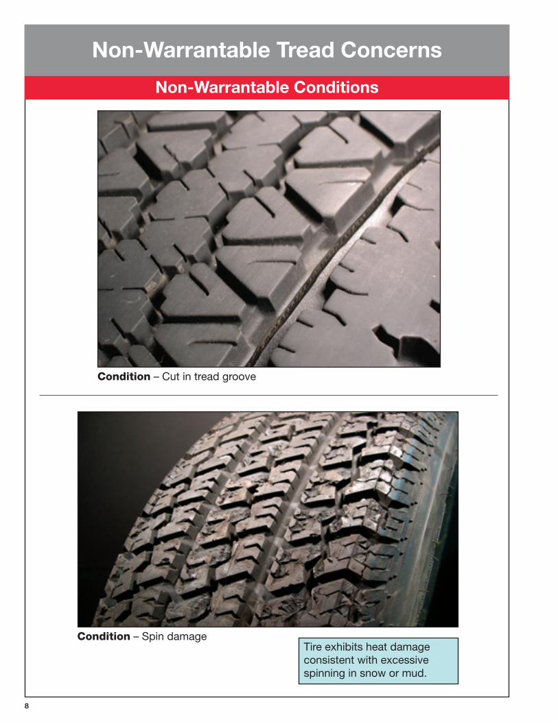
Condition – Cut in tread groove
Tire exhibits heat damage consistent with excessive spinning in snow or mud.
Condition – Spin damage
Non-Warrantable Tread Concerns
Non-Warrantable Conditions
�
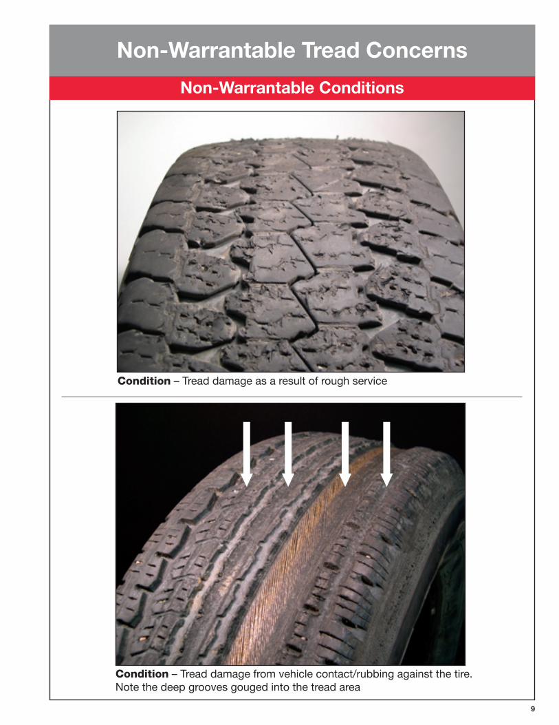
Condition – Tread damage from vehicle contact/rubbing against the tire. Note the deep grooves gouged into the tread area
Non-Warrantable Tread Concerns
Non-Warrantable Conditions
Condition – Tread damage as a result of rough service
10
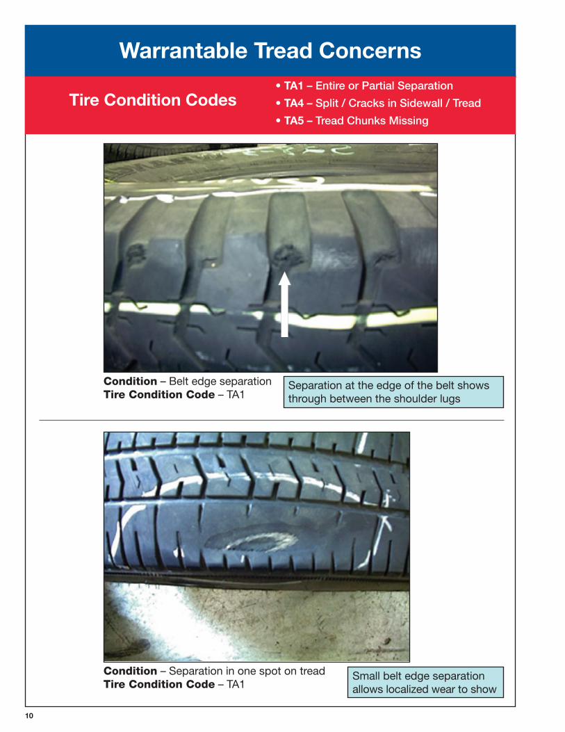
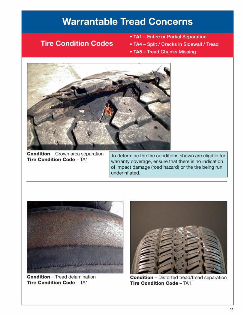
Warrantable Tread Concerns• TA1 – Entire or Partial Separation
• TA� – Split / Cracks in Sidewall / Tread
• TA� – Tread Chunks Missing
Separation at the edge of the belt shows through between the shoulder lugs
Small belt edge separation allows localized wear to show
Condition – Belt edge separation TireConditionCode – TA1
Condition – Separation in one spot on tread TireConditionCode – TA1
Tire Condition Codes
11
To determine the tire conditions shown are eligible for warranty coverage, ensure that there is no indication of impact damage (road hazard) or the tire being run underinflated.
Condition – Tread delamination TireConditionCode – TA1
Condition – Distorted tread/tread separation TireConditionCode – TA1
Condition – Crown area separation TireConditionCode – TA1
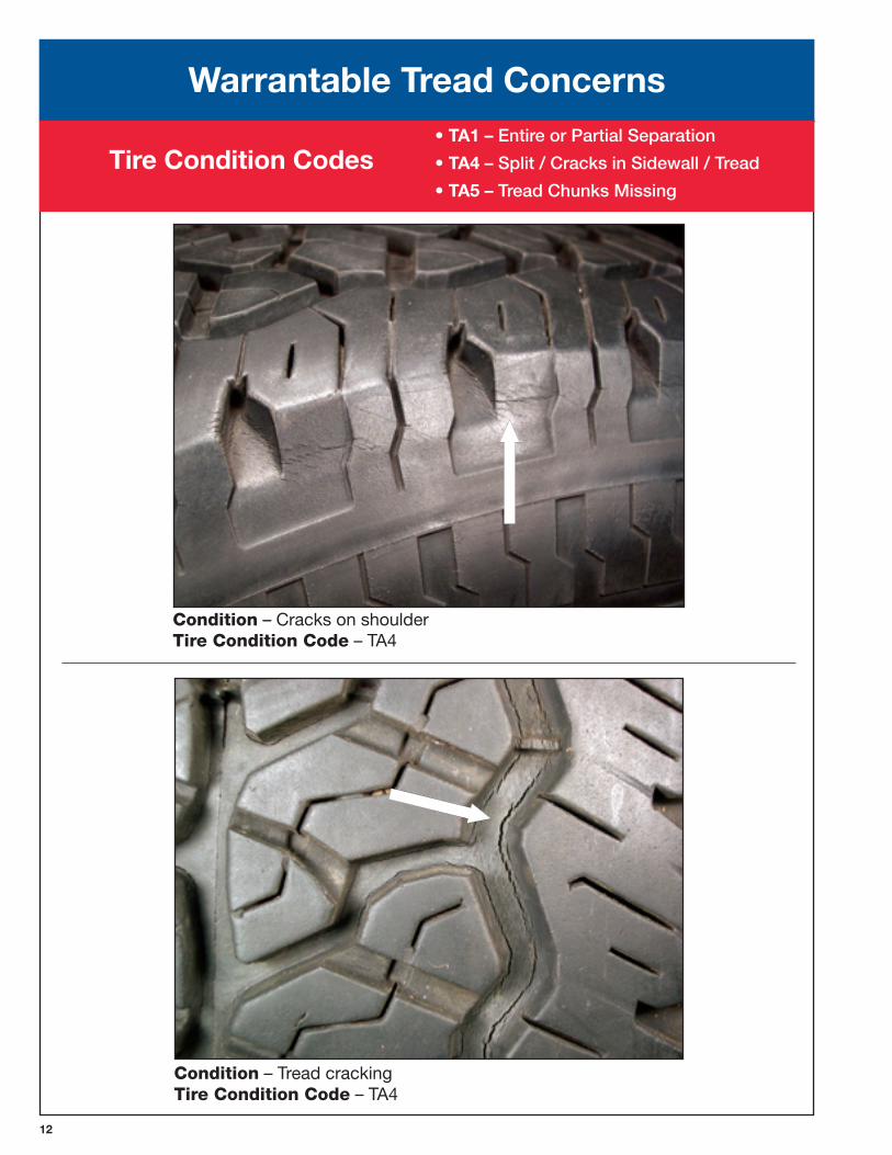
Warrantable Tread Concerns• TA1 – Entire or Partial Separation
• TA� – Split / Cracks in Sidewall / Tread
• TA� – Tread Chunks Missing
Tire Condition Codes
12
Condition – Tread cracking TireConditionCode – TA4
Condition – Cracks on shoulder TireConditionCode – TA4
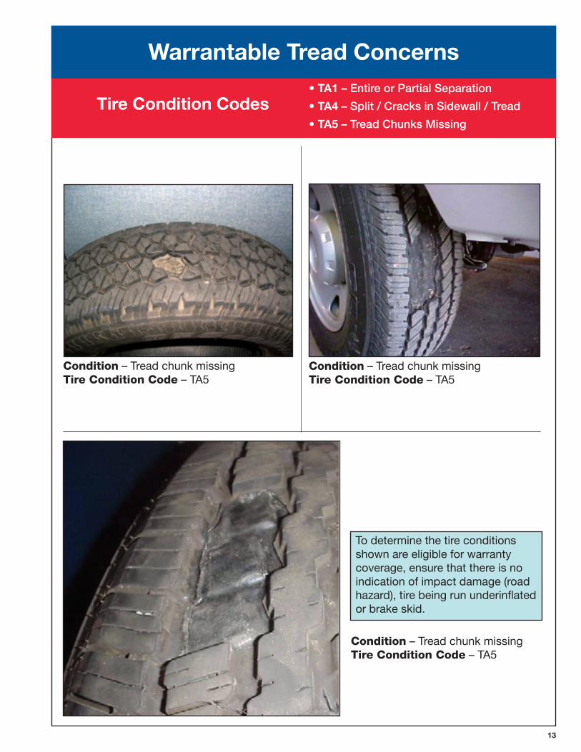
Warrantable Tread Concerns• TA1 – Entire or Partial Separation
• TA� – Split / Cracks in Sidewall / Tread
• TA� – Tread Chunks Missing
Tire Condition Codes
1�
To determine the tire conditions shown are eligible for warranty coverage, ensure that there is no indication of impact damage (road hazard), tire being run underinflated or brake skid.
Condition – Tread chunk missing TireConditionCode – TA5
Condition – Tread chunk missing TireConditionCode – TA5
Condition – Tread chunk missing TireConditionCode – TA5
Warrantable Tread Concerns• TA1 – Entire or Partial Separation
• TA� – Split / Cracks in Sidewall / Tread
• TA� – Tread Chunks Missing
Tire Condition Codes
1�
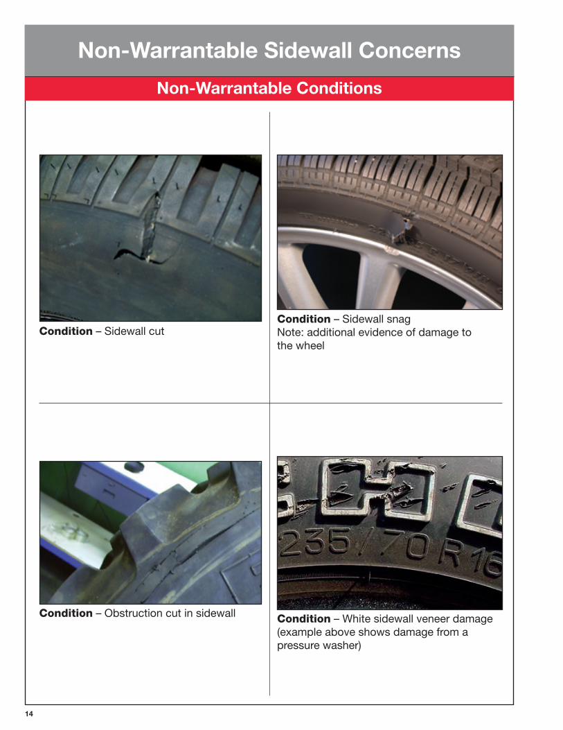
Condition – Obstruction cut in sidewall
Condition – Sidewall snag Note: additional evidence of damage to the wheel
Condition – Sidewall cut
Condition – White sidewall veneer damage (example above shows damage from a pressure washer)
Non-Warrantable Sidewall Concerns
Non-Warrantable Conditions
1�
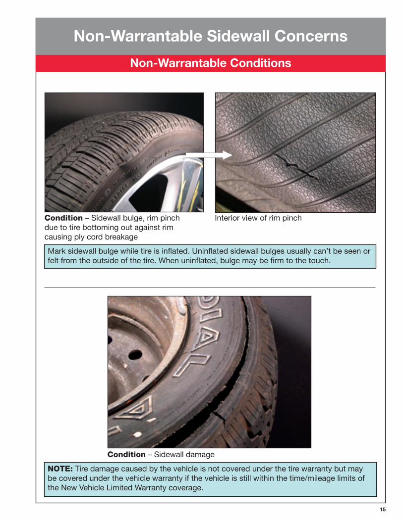
Mark sidewall bulge while tire is inflated. Uninflated sidewall bulges usually can’t be seen or felt from the outside of the tire. When uninflated, bulge may be firm to the touch.
Condition – Sidewall bulge, rim pinch due to tire bottoming out against rim causing ply cord breakage
Interior view of rim pinch
NOTE: Tire damage caused by the vehicle is not covered under the tire warranty but may be covered under the vehicle warranty if the vehicle is still within the time/mileage limits of the New Vehicle Limited Warranty coverage.
Condition – Sidewall damage
Non-Warrantable Sidewall Concerns
Non-Warrantable Conditions
16
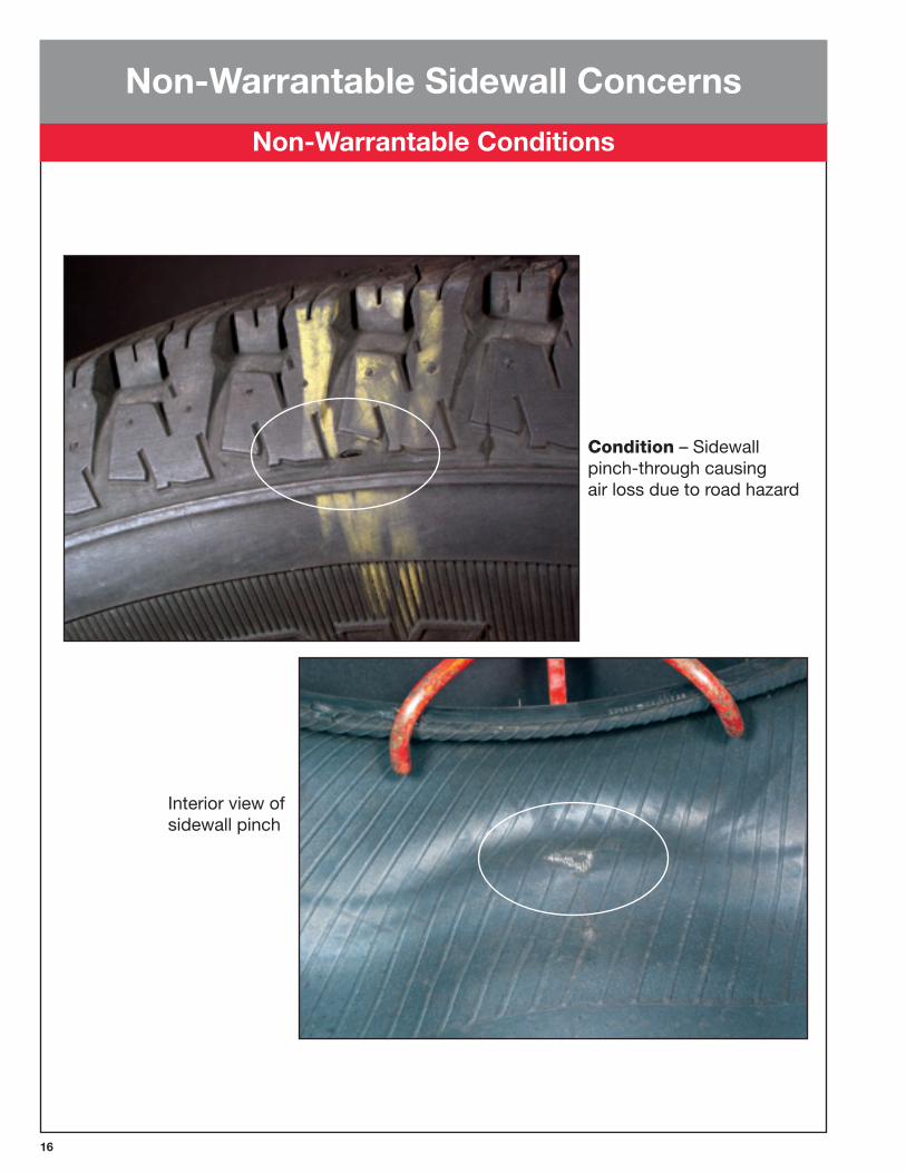
Condition – Sidewall pinch-through causing air loss due to road hazard
Interior view of sidewall pinch
Non-Warrantable Sidewall Concerns
Non-Warrantable Conditions
1�
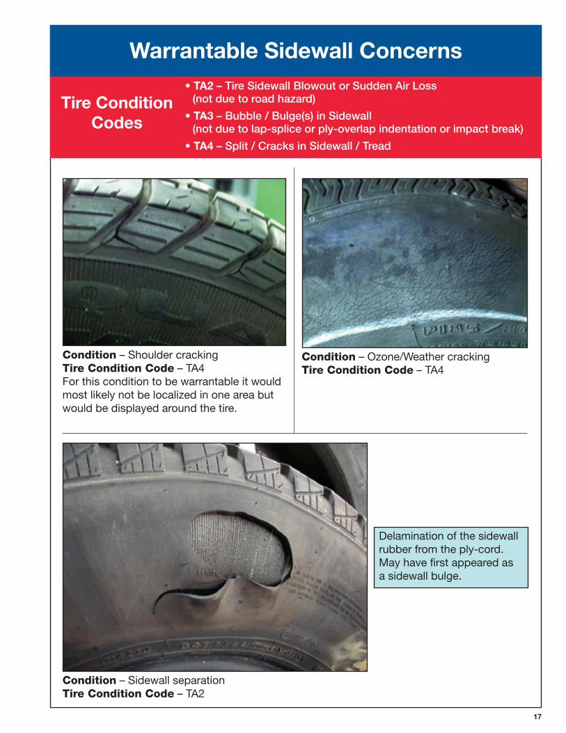
Condition – Ozone/Weather cracking TireConditionCode – TA4
Condition – Shoulder cracking TireConditionCode – TA4 For this condition to be warrantable it would most likely not be localized in one area but would be displayed around the tire.
Delamination of the sidewall rubber from the ply-cord. May have first appeared as a sidewall bulge.
Condition – Sidewall separation TireConditionCode – TA2
Warrantable Sidewall Concerns• TA2 – Tire Sidewall Blowout or Sudden Air Loss
(not due to road hazard)
• TA� – Bubble / Bulge(s) in Sidewall (not due to lap-splice or ply-overlap indentation or impact break)
• TA� – Split / Cracks in Sidewall / Tread
Tire Condition Codes
1�
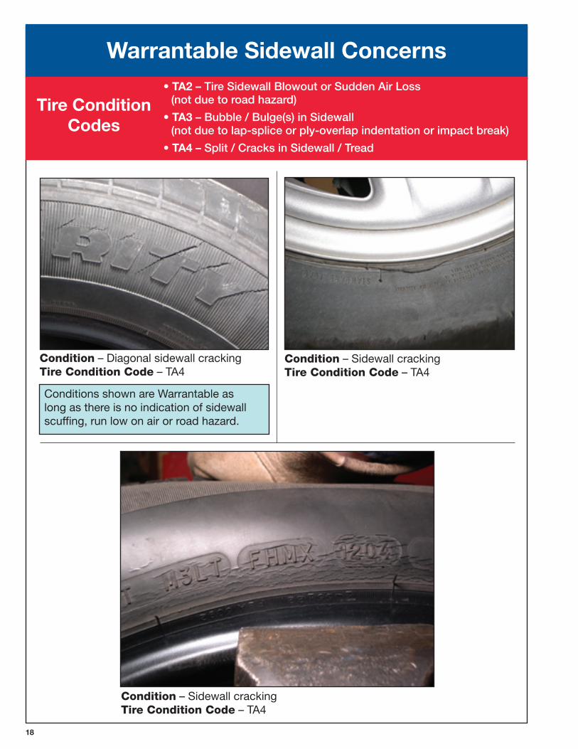
Conditions shown are Warrantable as long as there is no indication of sidewall scuffing, run low on air or road hazard.
Condition – Diagonal sidewall cracking TireConditionCode – TA4
Condition – Sidewall cracking TireConditionCode – TA4
Condition – Sidewall crackingTireConditionCode – TA4
Warrantable Sidewall Concerns• TA2 – Tire Sidewall Blowout or Sudden Air Loss
(not due to road hazard)
• TA� – Bubble / Bulge(s) in Sidewall (not due to lap-splice or ply-overlap indentation or impact break)
• TA� – Split / Cracks in Sidewall / Tread
Tire Condition Codes
1�
Warrantable Sidewall Concerns• TA2 – Tire Sidewall Blowout or Sudden Air Loss
(not due to road hazard)
• TA� – Bubble / Bulge(s) in Sidewall (not due to lap-splice or ply-overlap indentation or impact break)
• TA� – Split / Cracks in Sidewall / Tread
Tire Condition Codes
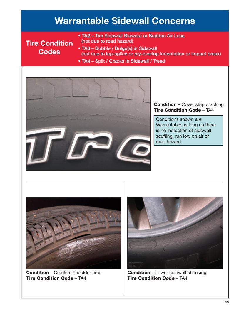
Condition – Cover strip cracking TireConditionCode – TA4
Conditions shown are Warrantable as long as there is no indication of sidewall scuffing, run low on air or road hazard.
Condition – Crack at shoulder area TireConditionCode – TA4
Condition – Lower sidewall checking TireConditionCode – TA4
20
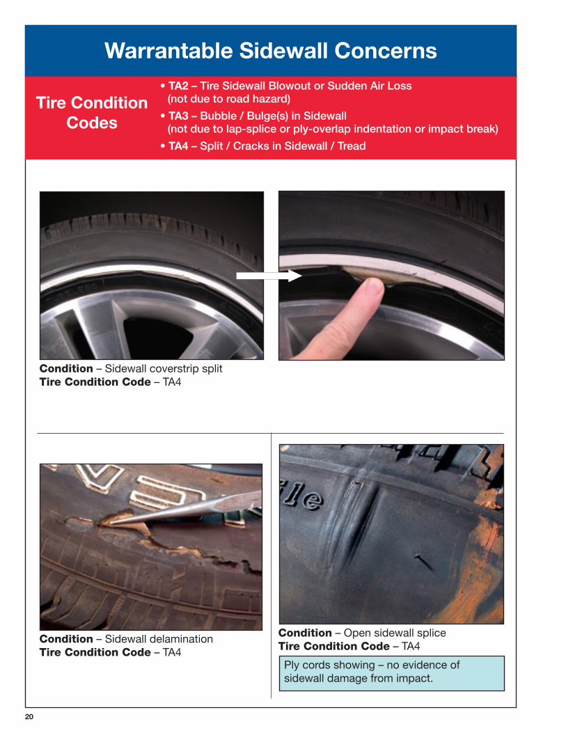
Condition – Sidewall delamination TireConditionCode – TA4
Ply cords showing – no evidence of sidewall damage from impact.
Condition – Open sidewall splice TireConditionCode – TA4
Warrantable Sidewall Concerns• TA2 – Tire Sidewall Blowout or Sudden Air Loss
(not due to road hazard)
• TA� – Bubble / Bulge(s) in Sidewall (not due to lap-splice or ply-overlap indentation or impact break)
• TA� – Split / Cracks in Sidewall / Tread
Tire Condition Codes
Condition – Sidewall coverstrip split TireConditionCode – TA4
21
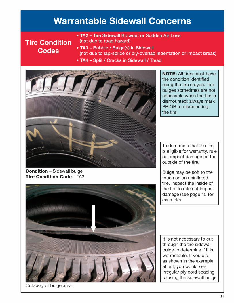
Condition – Sidewall bulge TireConditionCode – TA3
Cutaway of bulge area
NOTE: All tires must have the condition identified using the tire crayon. Tire bulges sometimes are not noticeable when the tire is dismounted; always mark PRIOR to dismounting the tire.
To determine that the tire is eligible for warranty, rule out impact damage on the outside of the tire.
Bulge may be soft to the touch on an uninflated tire. Inspect the inside of the tire to rule out impact damage (see page 15 for example).
It is not necessary to cut through the tire sidewall bulge to determine if it is warrantable. If you did, as shown in the example at left, you would see irregular ply cord spacing causing the sidewall bulge
Warrantable Sidewall Concerns• TA2 – Tire Sidewall Blowout or Sudden Air Loss
(not due to road hazard)
• TA� – Bubble / Bulge(s) in Sidewall (not due to lap-splice or ply-overlap indentation or impact break)
• TA� – Split / Cracks in Sidewall / Tread
Tire Condition Codes
22
Warrantable Sidewall Concerns• TA2 – Tire Sidewall Blowout or Sudden Air Loss
(not due to road hazard)
• TA� – Bubble / Bulge(s) in Sidewall (not due to lap-splice or ply-overlap indentation or impact break)
• TA� – Split / Cracks in Sidewall / Tread
Tire Condition Codes
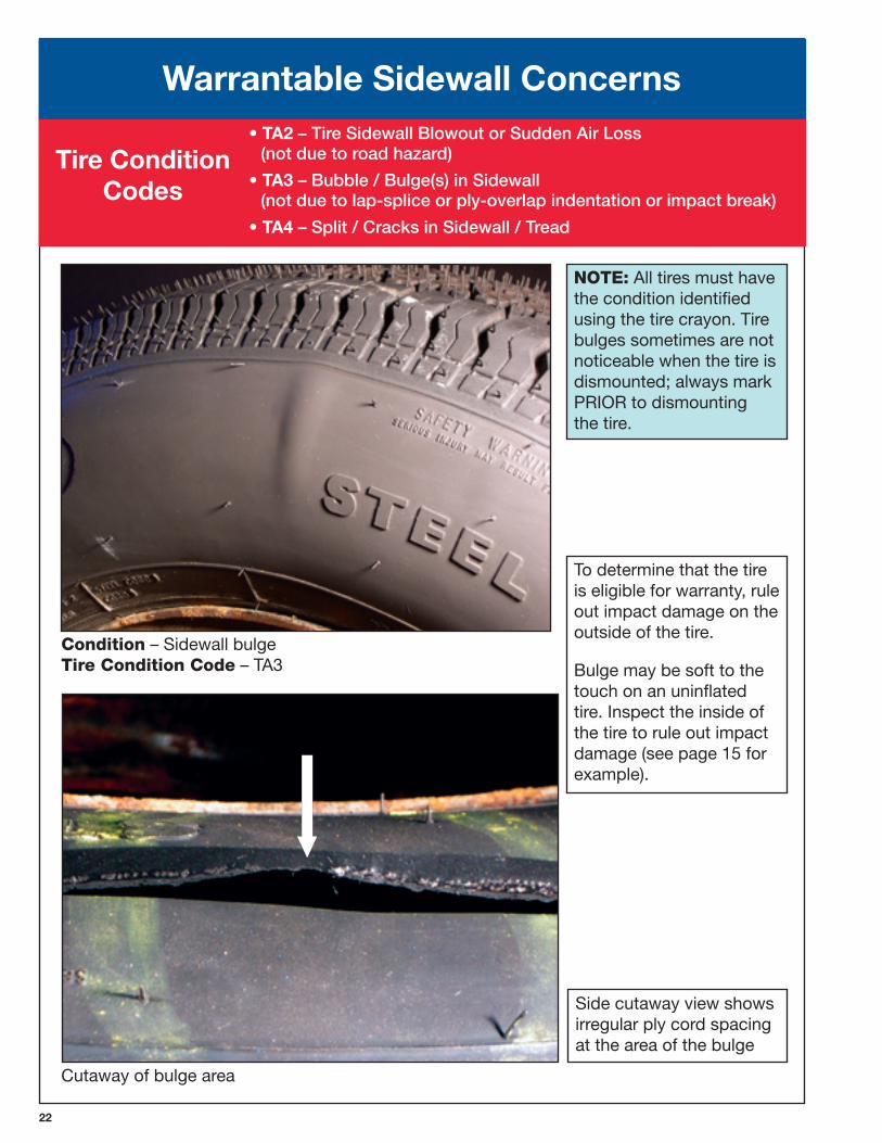
Condition – Sidewall bulge TireConditionCode – TA3
Cutaway of bulge area
NOTE: All tires must have the condition identified using the tire crayon. Tire bulges sometimes are not noticeable when the tire is dismounted; always mark PRIOR to dismounting the tire.
To determine that the tire is eligible for warranty, rule out impact damage on the outside of the tire.
Bulge may be soft to the touch on an uninflated tire. Inspect the inside of the tire to rule out impact damage (see page 15 for example).
Side cutaway view shows irregular ply cord spacing at the area of the bulge
Warrantable Sidewall Concerns• TA2 – Tire Sidewall Blowout or Sudden Air Loss
(not due to road hazard)
• TA� – Bubble / Bulge(s) in Sidewall (not due to lap-splice or ply-overlap indentation or impact break)
• TA� – Split / Cracks in Sidewall / Tread
Tire Condition Codes
Warrantable Sidewall Concerns• TA2 – Tire Sidewall Blowout or Sudden Air Loss
(not due to road hazard)
• TA� – Bubble / Bulge(s) in Sidewall (not due to lap-splice or ply-overlap indentation or impact break)
• TA� – Split / Cracks in Sidewall / Tread
Tire Condition Codes
2�
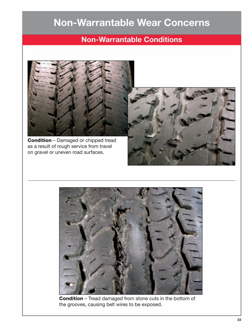
Condition – Damaged or chipped tread as a result of rough service from travel on gravel or uneven road surfaces.
Condition – Tread damaged from stone cuts in the bottom of the grooves, causing belt wires to be exposed.
Non-Warrantable Wear Concerns
Non-Warrantable Conditions
2�
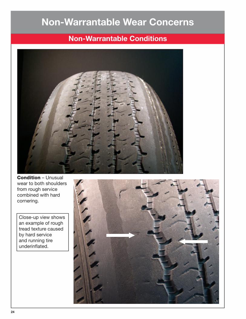
Condition – Unusual wear to both shoulders from rough service combined with hard cornering.
Close-up view shows an example of rough tread texture caused by hard service and running tire underinflated.
Non-Warrantable Wear Concerns
Non-Warrantable Conditions
2�
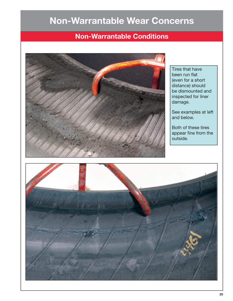
Tires that have been run flat (even for a short distance) should be dismounted and inspected for liner damage.
See examples at left and below.
Both of these tires appear fine from the outside.
Non-Warrantable Wear Concerns
Non-Warrantable Conditions
26
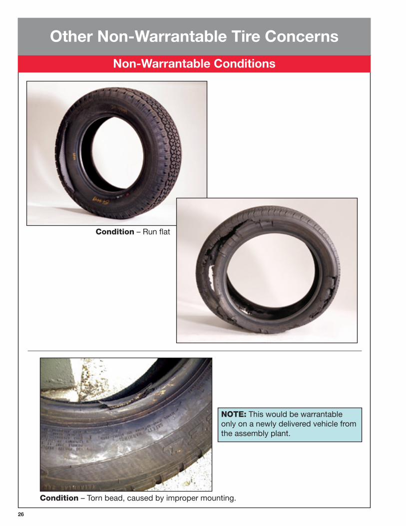
NOTE: This would be warrantable only on a newly delivered vehicle from the assembly plant.
Condition – Torn bead, caused by improper mounting.
Other Non-Warrantable Tire Concerns
Non-Warrantable Conditions
Condition – Run flat
2�
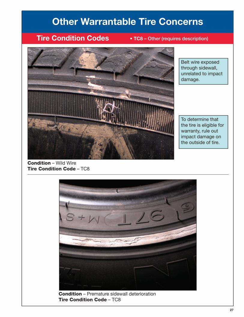
Belt wire exposed through sidewall, unrelated to impact damage.
Condition – Wild Wire TireConditionCode – TC8
To determine that the tire is eligible for warranty, rule out impact damage on the outside of tire.
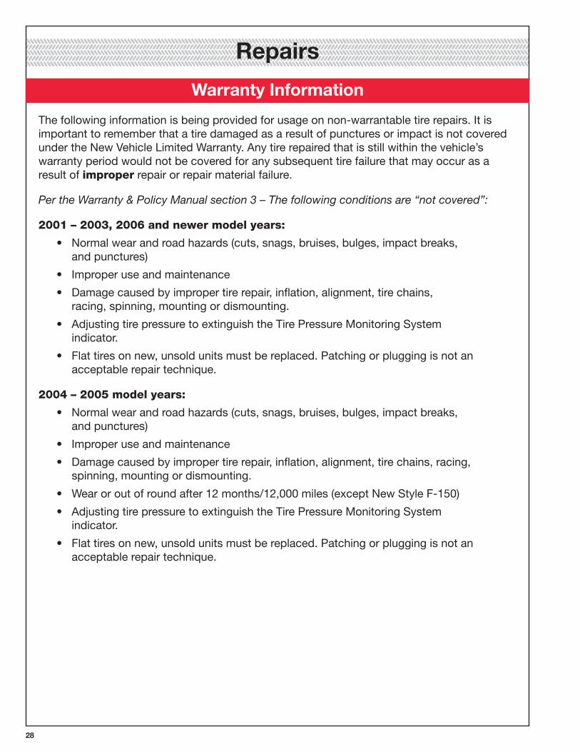
Condition – Premature sidewall deterioration TireConditionCode – TC8
Other Warrantable Tire Concerns
• TC� – Other (requires description) Tire Condition Codes
2�
The following information is being provided for usage on non-warrantable tire repairs. It is important to remember that a tire damaged as a result of punctures or impact is not covered under the New Vehicle Limited Warranty. Any tire repaired that is still within the vehicle’s warranty period would not be covered for any subsequent tire failure that may occur as a result of improper repair or repair material failure.
Per the Warranty & Policy Manual section 3 – The following conditions are “not covered”:
2001–2003,2006andnewermodelyears:
• Normal wear and road hazards (cuts, snags, bruises, bulges, impact breaks, and punctures)
• Improper use and maintenance
• Damage caused by improper tire repair, inflation, alignment, tire chains, racing, spinning, mounting or dismounting.
• Adjusting tire pressure to extinguish the Tire Pressure Monitoring System indicator.
• Flat tires on new, unsold units must be replaced. Patching or plugging is not an acceptable repair technique.
2004–2005modelyears:
• Normal wear and road hazards (cuts, snags, bruises, bulges, impact breaks, and punctures)
• Improper use and maintenance
• Damage caused by improper tire repair, inflation, alignment, tire chains, racing, spinning, mounting or dismounting.
• Wear or out of round after 12 months/12,000 miles (except New Style F-150)
• Adjusting tire pressure to extinguish the Tire Pressure Monitoring System indicator.
• Flat tires on new, unsold units must be replaced. Patching or plugging is not an acceptable repair technique.
Warranty Information
Repairs
2�
PunctureRepairProceduresforPassengerCar&LightTruckTires: The following information is being provided to assist Ford, Mercury & Lincoln dealers with making appropriate repairs to damaged tires. This is not intended to imply that tire damage resulting from road hazards or improper maintenance is warrantable.
Recommendedproceduresforalltirerepairtechniciansandfacilities:
Beforeperformingapuncturerepair,readthissection!
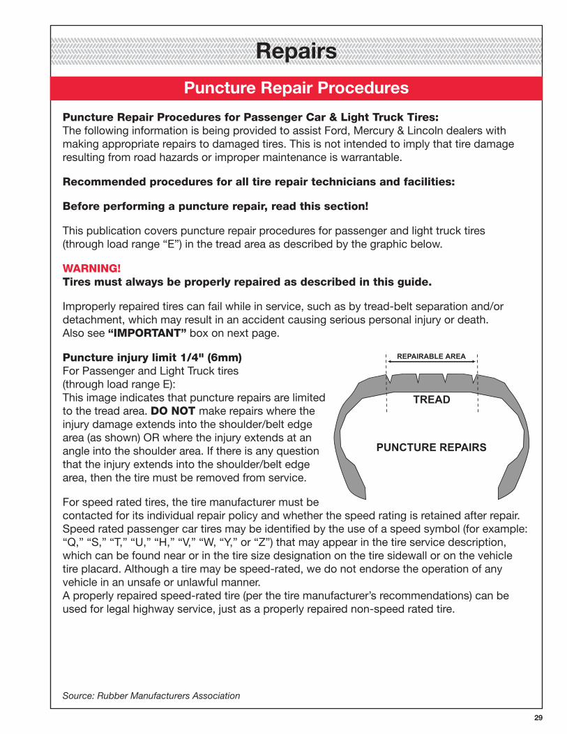
This publication covers puncture repair procedures for passenger and light truck tires (through load range “E”) in the tread area as described by the graphic below.
WARNING!Tiresmustalwaysbeproperlyrepairedasdescribedinthisguide.
Improperly repaired tires can fail while in service, such as by tread-belt separation and/or detachment, which may result in an accident causing serious personal injury or death. Also see “IMPORTANT” box on next page.
Punctureinjurylimit1/4"(6mm) For Passenger and Light Truck tires (through load range E): This image indicates that puncture repairs are limited to the tread area. DONOTmake repairs where the injury damage extends into the shoulder/belt edge area (as shown) OR where the injury extends at an angle into the shoulder area. If there is any question that the injury extends into the shoulder/belt edge area, then the tire must be removed from service.
For speed rated tires, the tire manufacturer must be contacted for its individual repair policy and whether the speed rating is retained after repair. Speed rated passenger car tires may be identified by the use of a speed symbol (for example: “Q,” “S,” “T,” “U,” “H,” “V,” “W, “Y,” or “Z”) that may appear in the tire service description, which can be found near or in the tire size designation on the tire sidewall or on the vehicle tire placard. Although a tire may be speed-rated, we do not endorse the operation of any vehicle in an unsafe or unlawful manner. A properly repaired speed-rated tire (per the tire manufacturer’s recommendations) can be used for legal highway service, just as a properly repaired non-speed rated tire.
Source: Rubber Manufacturers Association
Puncture Repair Procedures
Repairs
�0
Puncture Repair ProceduresIMPORTANT! • Not all tires can be repaired. Specific repair limits should be based on recommendations or repair policy of the tire manufacturer and/or type of tire service (e.g. service description, run-flat technology, commercial service applications, etc.).
• For all tires, repair units cannot overlap. The number of repairs should be limited first by the tire manufacturer’s recommendations and repair policy and then by application and the individual tire’s condition as determined by the inspection process detailed in Steps 1 and 2.
• Some run-flat technology tires cannot be repaired. Consult tire manufacturer for their repair policy and, if applicable, for their recommended repair procedures.
• Industry recommended repair methods include: (1) Two-piece stem and patch repair components, and (2) one-piece patch/stem combination repair units. For punctures angled greater than 25°, two-piece stem and patch repair components are recommended (see Step 2). NEVER use only a plug (stem) orNEVER use only a patch to repair a puncture.
WARNING!Neverperformatirerepairwithoutremovingthetirefromtherim/wheelassemblyforinternalinspection.
(DONOTperformanoutside-intirerepairoron-the-wheelrepair.)Drivingonthetireashortdistancewhileitisseverelyunderinflatedcancausedangerous,non-repairabledamagethatisnotvisiblefromtheoutside.Everytiremustberemovedfromthewheelforinspectionandtoassessrepairability(steps1&2). Only specially trained personnel using the proper tools and procedures should repair tires.
NEVER repair tires with a tread puncture larger than 1/4" (6mm).
NEVER repair tires worn to the tire’s treadwear indicators or to 2/32" remaining tread depth in any area of the tread.
NEVER perform a tire repair without removing the tire from the rim/wheel assembly for internal inspection. (DONOT perform an outside-in tire repair or on-the-wheel repair). It is essential that only a specially trained person remove any tire from the wheel when it has been damaged or is losing air. A thorough inspection for any internal damage can then be made. See WARNINGS.
NEVER use only a plug (stem) orNEVER use only a patch to repair a puncture. The injury must be completely filled with a suitable vulcanizing material or rubber stem and a patch must be applied to the inner liner to prevent air loss.
NEVER repair a tire that has an existing, improper repair; the tire must be removed from service.
NEVER substitute an inner tube for a proper repair or to remedy an improper repair.
NEVER invert radial tires. (Avoid excessive spreading of the tire or tire beads.)
NEVER buff the tire inner liner too deep, exposing the tire casing body (ply) cords. If this type of damage occurs during buffing, the tire must be removed from service.
Source: Rubber Manufacturers Association
Repairs
�1
WARNING! Tirechangingcanbedangerousandshouldbedonebytrainedpersonnelusingpropertoolsandprocedures.Alwaysreadandunderstandanymanufacturer’swarningcontainedintheircustomers’literatureormoldedintothetiresidewall. Failure to comply with these procedures may result in faulty positioning of the tire and/or rim parts and cause the assembly to burst with explosive force, sufficient to cause serious physical injury or death. Never mount or use damaged tires or rims.
Formoreontiremountingsafetyandprocedures refer to the RMA Demounting and Mounting Procedures for Automobile and Light Truck Tires wall chart.
WARNING! Tiresmustalwaysbeproperlyrepairedasdescribedinthisguide. Improperly repaired tires can fail while in service, such as by tread-belt separation and/or detachment, which may result in an accident causing serious personal injury or death.
WARNING! Serious eye or ear injuries may result from not wearing adequate eye goggles (or face shields) and ear protection while repairing tires.
As explicitly illustrated in the following ten steps, the basic principles for puncture repairing are: to remove the tire from the wheel for inspection and repair; to prepare the injured area; to fill the injury with a suitable, vulcanizing material or rubber stem that must fill the injury and keep moisture out; to seal the inner liner with a patch repair unit to prevent air loss; and, to re-inspect the finished repair.
Source: Rubber Manufacturers Association
Puncture Repair Procedures
Repairs
�2
STEP1 EXTERNALINSPECTION
Prior to demounting, check tire surface and the valve for the source of the leak(s) by using water or a soap solution. Mark the injured area and totally deflate the tire. Then remove the tire from the wheel being careful to avoid further damage to the tire, particularly to the bead area. Place on a well-lighted spreader. (Avoid excessive spreading of the tire or tire beads.) ALWAYS inspect tires internally and externally prior to installation of any repair. A minimum of 200 foot candles of lighting is required – 300 foot candles is recommended—at the surface being inspected. A hand-held inspection light can help ensure that these conditions are met both inside and outside the tire. Consult your equipment supplier for appropriate lighting.
WARNING! Permanenttiredamageduetounderinflationand/oroverloadingcannotalwaysbedetected.Anytireknown,orsuspectedtohavebeenrunatlessthantheplacardrecommendedoperatinginflationpressureand/oroverloaded,couldpossiblyhavepermanentstructuraldamage(cordfatigue,particularlysteelcordsorbeltmaterial).Seeexamplesonpage26.Plycordsweakenedbyunderinflationand/oroverloadingmaybreakoneafteranotheruntilarupture,commonlyreferredtoasa“zipper,”occursintheuppersidewallwithaccompanyinginstantaneousairlossandexplosiveforce.Thiscanresultinseriousinjuryordeath.Thesetiresshouldbeinflatedbyusingarestrainingdevice(orsafetycage)thatcomplieswithOSHAregulationsandanairlinewithaclip-onairchuck.
STEP2 INTERNALINSPECTION
Spread the beads and mark the injury with a tire crayon. Remove the puncturing object noting the angle of penetration. Probe the injury with a blunt awl to determine the extent and direction of the injury and remove any loose foreign material. If the angle of the injury exceeds 25°, use a two-piece repair system. Do not repair if injury extends into the shoulder/belt edge area and never repair in the sidewall area. For all tires, repair units cannot overlap. Inspect for any other internal damage. Tires with damage due to underinflation, overloading, and/or tires with an existing improper repair must be removed from service. (See“IMPORTANT” box on page 30.)
Source: Rubber Manufacturers Association
Puncture Repair Procedures
Repairs
��
STEP3 PREPAREINNERLINERSURFACE
Clean the area around the puncture thoroughly with an appropriate (pre-buff) inner liner cleaner. Use a clean cloth and/or scraper, according to repair material manufacturer’s recommendations. Consult your local repair materials supplier for an appropriate cleaner. This step serves to remove dirt and mold lubricants that can reduce repair unit adhesion and contaminate buffing tools.
1. Tiresthatcontainanytypeofaftermarketpuncturesealant(s)may havebeendamagedasaresultofbeingrununderinflatedand/or overloadedandshouldbeinspectedaccordingly.
2. Tiresthataremanufacturedwithpuncturesealantrequirespecialized repairingtechniques.Thetireand/orsealantmanufacturer(s)should becontactedforrecommendations.
STEP4 PREPAREINJURYCHANNEL
All damage must be removed. Use an electric/air powered drill (1,200 rpm max.) with an appropriate size carbide cutter or other suitable tool. Beginning from the inside, ream the puncture channel a minimum of three times – repeat from the outside. Use a probe to check for any splits in the radial plies surrounding the injury. Remove any additional damage found.
STEP5 REPAIRUNITSELECTION
Select the appropriate size repair unit, based on repair material manufacturer’s recommendations. Center the unit over the injury and outline an area 1/2" (13mm) larger than the repair unit, so buffing will not remove the crayon marks.
Source: Rubber Manufacturers Association
Puncture Repair Procedures
Repairs
��
STEP6 FILLINJURY
For a two-piece repair, follow instructions below. For a one-piece (combination) repair unit, skip this step. DONOT mix products from different repair material manufacturers. Follow repair material manufacturer application recommendations. Note: Refer to information on the product or manufacturer Material Safety Data Sheet and follow guidelines for handling and disposal.
Cement the puncture channel per recommendations. Completely fill the injury from the inside of the tire with a suitable vulcanizing material or rubber stem. Without stretching the stem, cut the material off just above the inside tire surface. It is necessary to completely fill the injury to provide a backup for the patch repair unit and to prevent rusting of the steel wires or deterioration of fabric.
STEP7 BUFFING
To prevent contamination and preserve the outline, buff within the marked area thoroughly and evenly with a low speed buffer (5,000 rpm max.) with a fine wire brush or gritted rasp. Take care not to expose or damage tire casing body (ply) cords. Buff to a velvet surface; RMA No. 1 or No. 2 texture. NEVERbuff the tire inner liner too deep exposing the tire casing body (ply) cords. If this type of damage occurs during buffing, the tire must be scrapped.
Remove all rubber dust from the buffed area by using a fine wire brush and vacuum, being careful to avoid touching and contaminating the area. DONOT use compressed air to clean bonding surfaces; air lines contain contaminants such as oil and moisture, which reduce adhesion. Follow repair material manufacturer’s recommendations for cleaning the buffed area.
STEP8 CEMENTING
DONOT mix products from different repair material manufacturers. Note: Refer to information on the product or manufacturer Material Safety Data Sheet and follow guidelines for handling and disposal.
Apply chemical cement and allow it to dry according to repair material manufacturer’s procedures. DONOT use forced air or outside heat source to accelerate drying time. (In cold and/or humid climate conditions, adjust drying time.)
WARNING!DONOT use flammable cements near fire, flame or any other source of ignition. Explosive force and/or fire from ignition of cement could cause serious injury or death.
Source: Rubber Manufacturers Association
Puncture Repair Procedures
Repairs
��
STEP9 REPAIRUNITAPPLICATION
DONOT mix products from different repair material manufacturers. Follow repair material manufacturer’s recommendations for installation instructions. Note: Refer to information on the product or manufacturer Material Safety Data Sheet and follow guidelines for handling and disposal.
The tire must be in a relaxed position when the repair unit is installed. (Do not spread the beads excessively.) Remove and discard protective covering being careful not to touch the bonding material on the repair unit. When using atwo-piece, directionally marked unit, install the unit so that the alignment is correct and centered over the injury. Next, stitch down thoroughly with a stitching tool, working from the center out. When using a one-piece, combination patch/stem repair unit, DONOTcement the stem, instead cement the injury channel. Next, pull the stem through the injury until the unit slightly dimples, then stitch down thoroughly with a stitching tool, working from the center out. Remove and discard the top protective covering. Cut the fill material flush with the outer tread surface while being careful not to stretch the stem.
INSPECTPATCHEDAREA! If the buffed area extends beyond the patch, look for any signs of tire casing body (ply) cords. DONOT continue the repair if the buffed area exposes the tire’s casing body (ply) cords; the tire must be removed from service.
STEP10 FINALINSPECTION
IMPORTANT! A proper repair must completely fill the injury with a suitable vulcanizing material or rubber stem and a patch must be applied to the inner liner to prevent air loss.
Inspect all repairs; rework if necessary. After remounting and inflating the tire/wheel assembly, inspect the assembly (tire/rim/valve) for damage or leakage. Pay particular attention to the location of the repair, the beads and the valve. If the tire continues to lose air, it must again be removed from the wheel for complete re-inspection. (For tube-type tires be sure to replace a damaged tube with a new tube.)
WARNING!Apatchonlyoraplug(stem)onlyisanimproperrepair.Improperlyrepairedtirescanfailwhileinservice,suchasbytread-beltseparationand/ordetachment,whichmayresultinanaccidentcausingseriouspersonalinjuryordeath.
Source: Rubber Manufacturers Association
Puncture Repair Procedures
Repairs
�6
For a more comprehensive treatment of tire conditions, see“ThePassengerandLightTruckTire Conditions Manual” (product code 700-862-918-10000), a publication of the:
TireIndustryAssociation1532 Pointer Ridge Place
Suite G Bowie, MD 20716-1883
Phone: 301-430-7280 or 800-876-8372 Fax: 301-430-7283
www.tireindustry.org
Contact the RMA to order the “Puncture Repair Procedures for Passenger and Light Truck Tires Wall Chart” Pub #: PRP-PLLT-1105, or for any other tire safety, care and service Information.
RubberManufacturersAssociation(RMA) 1400 K Street, NW,
Suite 900, Washington, DC 20005
Phone: 202-682-4800 or 800-220-7622 www.rma.org
Acknowledgements We would like to acknowledge the following companies for their participation in helping to develop this guide:
Tire Industry Association (TIA)
Rubber Manufacturers Association (RMA)
The Goodyear Tire and Rubber Company
References


FTCG 1.0 12/01/2006