Embed Size (px)
Citation preview

Timer/Counter/AnalyzersPM6680B, PM6681, PM6681R, PM6685 & PM6685R
Programming Manual

II
All rights reserved. Reproduction in whole or in part isprohibited without written consent of the copyright owner.TimeView is a trademark of Pendulum Instruments AB.
FLUKE is a trademark of Fluke Corporation.TimeView uses the SPAWNO routines by Ralf Brown to minimizememory use while shelling to DOS and running other programs.
Pendulum Instruments AB - Sweden - 2000

Table of Contents
1 Getting StartedFinding Your Way Through This Manual . . 1-2
Manual Conventions . . . . . . . . . . . . . . . . . 1-3
Setting Up the Instrument . . . . . . . . . . . . . 1-4
Interface Functions . . . . . . . . . . . . . . . . . . 1-5
2 Bus Commands for theBenchtop User
Default settings (after *RST). . . . . . . . . . . 2-8
3 Introduction to SCPIWhat is SCPI? . . . . . . . . . . . . . . . . . . . . . . 3-2
How does SCPI Work in the Instrument? . 3-4
Program and Response Messages . . . . . . 3-8
Command Tree . . . . . . . . . . . . . . . . . . . . 3-11
Parameters . . . . . . . . . . . . . . . . . . . . . . . 3-12
Macros. . . . . . . . . . . . . . . . . . . . . . . . . . . 3-15
Status Reporting System. . . . . . . . . . . . . 3-18
Error Reporting . . . . . . . . . . . . . . . . . . . . 3-19
Initialization and Resetting. . . . . . . . . . . . 3-21
4 Programming ExamplesIntroduction . . . . . . . . . . . . . . . . . . . . . . . . 4-2
GW-Basic for National InstrumentsPC-IIA . . . . . . . . . . . . . . . . . . . . . . . . 4-3
Setting up the interface . . . . . . . . . . . . . . . 4-3
1. Limit Testing . . . . . . . . . . . . . . . . . . . . . 4-4
3. Frequency Profiling . . . . . . . . . . . . . . . . 4-5
4. Fast Sampling . . . . . . . . . . . . . . . . . . . . 4-7
5. Status Reporting . . . . . . . . . . . . . . . . . . 4-9
6. Statistics . . . . . . . . . . . . . . . . . . . . . . . 4-11
‘C’ for National Instruments PC-IIA. . . . . . . . . . . . . . . . . . . . . . . . . . . . 4-13
1. Limit Testing . . . . . . . . . . . . . . . . . . . . 4-14
2. REAL Data Format . . . . . . . . . . . . . . . 4-15
3. Frequency Profiling . . . . . . . . . . . . . . . 4-17
4. Fast Sampling . . . . . . . . . . . . . . . . . . . 4-19
6. Statistics . . . . . . . . . . . . . . . . . . . . . . . 4-21
5 Instrument ModelIntroduction . . . . . . . . . . . . . . . . . . . . . . . . 5-2
Measurement Function Block . . . . . . . . . . 5-3
Other Subsystems . . . . . . . . . . . . . . . . . . . 5-4
Order of Execution. . . . . . . . . . . . . . . . . . . 5-4
MEASurement Function . . . . . . . . . . . . . . 5-5
6 Using the SubsystemsIntroduction . . . . . . . . . . . . . . . . . . . . . . . . 6-2
Calculate Subsystem. . . . . . . . . . . . . . . . . 6-3
Calibration Subsystem. . . . . . . . . . . . . . . . 6-4
Configure Function . . . . . . . . . . . . . . . . . . 6-5
Format Subsystem . . . . . . . . . . . . . . . . . . 6-6
Time Stamp Readout Format . . . . . . . . . . 6-6
Input Subsystems . . . . . . . . . . . . . . . . . . . 6-7
Measurement Function . . . . . . . . . . . . . . . 6-9
Output Subsystem. . . . . . . . . . . . . . . . . . 6-12
Sense Command Subsystems . . . . . . . . 6-14
Status Subsystem . . . . . . . . . . . . . . . . . . 6-15
Trigger/Arming Subsystem . . . . . . . . . . . 6-30
7 How to Measure FastIntroduction . . . . . . . . . . . . . . . . . . . . . . . . 7-3
Rough Trigger Subsystem Description . . . 7-4
Some Basic Commands . . . . . . . . . . . . . . 7-5
Basic Measurement Method . . . . . . . . . . . 7-7
III
4822 872 20081August 2000

General Speed Improvements. . . . . . . . . . 7-8
40000 measure- ments/second . . . . . . . . 7-11
Supervising a Process. . . . . . . . . . . . . . . 7-12
Speed Summary . . . . . . . . . . . . . . . . . . . 7-17
8 Error Messages
9 Command ReferenceAbort. . . . . . . . . . . . . . . . . . . . . . . . . 9-3
:ABORt . . . . . . . . . . . . . . . . . . . . . . . . . . . 9-4
Arming Subsystem . . . . . . . . . . . . . 9-5
:ARM :COUNt . . . . . . . . . . . . . . . . . . . . . . 9-6
:ARM :DELay. . . . . . . . . . . . . . . . . . . . . . . 9-7
:ARM :ECOunt. . . . . . . . . . . . . . . . . . . . . . 9-7
:ARM :LAYer2 . . . . . . . . . . . . . . . . . . . . . . 9-8
:ARM :LAYer2 :SOURce . . . . . . . . . . . . . . 9-8
:ARM :SLOPe . . . . . . . . . . . . . . . . . . . . . . 9-9
:ARM :SOURce . . . . . . . . . . . . . . . . . . . . . 9-9
:ARM :STOP :DELay . . . . . . . . . . . . . . . . 9-10
:ARM :STOP :ECOunt . . . . . . . . . . . . . . . 9-10
:ARM :STOP :SLOPe . . . . . . . . . . . . . . . 9-11
:ARM :STOP :SOURce . . . . . . . . . . . . . . 9-11
Calculate Subsystem . . . . . . . . . . 9-13
:CALCulate :AVERage :COUNt. . . . . . . . 9-14
:CALCulate :AVERage :STATe . . . . . . . . 9-14
:CALCulate :AVERage :TYPE. . . . . . . . . 9-15
:CALCulate :DATA?. . . . . . . . . . . . . . . . . 9-15
:CALCulate :IMMediate . . . . . . . . . . . . . . 9-16
:CALCulate :LIMit . . . . . . . . . . . . . . . . . . 9-16
:CALCulate :LIMit :FAIL?. . . . . . . . . . . . . 9-17
:CALCulate :LIMit :LOWer . . . . . . . . . . . . 9-17
:CALCulate :LIMit :LOWer :STATe . . . . . 9-18
:CALCulate :LIMit :UPPer . . . . . . . . . . . . 9-18
:CALCulate :LIMit :UPPer :STATe. . . . . . 9-19
:CALCulate :MATH . . . . . . . . . . . . . . . . . 9-20
:CALCulate :MATH . . . . . . . . . . . . . . . . . 9-21
:CALCulate :MATH :STATe. . . . . . . . . . . 9-21
:CALCulate :STATe. . . . . . . . . . . . . . . . . 9-22
Calibration Subsystem . . . . . . . . . 9-23
:CALibration :INTerpolator :AUTO. . . . . . 9-24
Configure Function . . . . . . . . . . . . 9-25
:CONFigure :<Measuring Function> . . . . 9-26
:CONFigure :ARRay :<MeasuringFunction> . . . . . . . . . . . . . . . . . . . . . . . 9-27
Diagnostics Subsystem . . . . . . . . 9-29
:DIAGnostic:CALibration:INPut[1|2]:HYSTeresis . . . . . . . . . . . . . . . . . . . . . . . . . . . . . . 9-30
Display Subsystem . . . . . . . . . . . . 9-31
:DISPlay :ENABle . . . . . . . . . . . . . . . . . . 9-32
Fetch Function. . . . . . . . . . . . . . . . 9-33
:FETCh? . . . . . . . . . . . . . . . . . . . . . . . . . 9-34
:FETCh :ARRay?. . . . . . . . . . . . . . . . . . . 9-35
Format Subsystem . . . . . . . . . . . . 9-37
:FORMat . . . . . . . . . . . . . . . . . . . . . . . . . 9-38
:FORMat . . . . . . . . . . . . . . . . . . . . . . . . . 9-38
:FORMat :FIXed . . . . . . . . . . . . . . . . . . . 9-39
:FORMat :SREGister . . . . . . . . . . . . . . . . 9-39
:FORMat :TINFormation . . . . . . . . . . . . . 9-40
Initiate Subsystem. . . . . . . . . . . . . 9-41
:INITiate :CONTinuous . . . . . . . . . . . . . . 9-42
:INITiate . . . . . . . . . . . . . . . . . . . . . . . . . . 9-42
Input Subsystems . . . . . . . . . . . . . 9-43
:INPut«[1]|2» :COUPling . . . . . . . . . . . . . 9-44
:INPut«[1]|2» :ATTenuation . . . . . . . . . . . 9-44
:INPut :HYSTeresis . . . . . . . . . . . . . . . . . 9-45
:INPut :FILTer . . . . . . . . . . . . . . . . . . . . . 9-45
:INPut :HYSTeresis :AUTO . . . . . . . . . . . 9-46
:INPut«[1]|2» :IMPedance . . . . . . . . . . . . 9-47
:INPut«[1]|2» :LEVel . . . . . . . . . . . . . . . . 9-47
:INPut :LEVel . . . . . . . . . . . . . . . . . . . . . . 9-48
:INPut :LEVel :AUTO. . . . . . . . . . . . . . . . 9-49
:INPut :LEVel :AUTO. . . . . . . . . . . . . . . . 9-50
:INPut«[1]|2|4» :SLOPe . . . . . . . . . . . . . . 9-51
:INPut2:COMMon . . . . . . . . . . . . . . . . . . 9-51
Measurement Function . . . . . . . . . 9-53
:MEASure :<Measuring Function>? . . . . 9-56
:MEASure :ARRay :<Measuring Function>?. . . . . . . . . . . . . . . . . . . . . . . . . . . . . . . 9-57
:MEASure:MEMory<N>? . . . . . . . . . . . . . 9-58
:MEASure:MEMory? . . . . . . . . . . . . . . . . 9-58
:MEASure_«:DCYCle/:PDUTycycle» . . . 9-59
EXPLANATIONS OF THE MEASURINGFUNCTIONS . . . . . . . . . . . . . . . . . . 9-59
:MEASure :FREQuency?. . . . . . . . . . . . . 9-60
:MEASure :FREQuency :BURSt? . . . . . . 9-61
:MEASure :FREQuency :PRF? . . . . . . . . 9-62
:MEASure :FALL :TIME?. . . . . . . . . . . . . 9-63
IV

:MEASure :FREQuency :RATio?. . . . . . . 9-63
:MEASure [:VOLT] :MAXimum? . . . . . . . 9-64
:MEASure [:VOLT] :MINimum? . . . . . . . . 9-64
:MEASure :NWIDth? . . . . . . . . . . . . . . . . 9-65
:MEASure :PWIDth? . . . . . . . . . . . . . . . . 9-65
:MEASure_«:PDUTycycle/ :DCYCle»? . . 9-66
:MEASure_«:NDUTycycle»? . . . . . . . . . . 9-66
:MEASure :PERiod? . . . . . . . . . . . . . . . . 9-67
:MEASure :PHASe? . . . . . . . . . . . . . . . . 9-67
:MEASure [:VOLT] :PTPeak? . . . . . . . . . 9-68
:MEASure :RISE :TIME? . . . . . . . . . . . . . 9-68
:MEASure :TINTerval? . . . . . . . . . . . . . . 9-69
:MEASure :TOTalize :ACCumulated? . . . 9-70
:CONFigure :TOTalize :CONTinuous . . . 9-71
:MEASure :TOTalize :GATed? . . . . . . . . 9-72
:MEASure :TOTalize :SSTop?. . . . . . . . . 9-72
:MEASure :TOTalize :TIMed? . . . . . . . . . 9-73
Memory Subsystem . . . . . . . . . . . 9-75
:MEMory :DELete :MACRo . . . . . . . . . . . 9-76
:MEMory :FREE :SENSe?. . . . . . . . . . . . 9-76
:MEMory :FREE :MACRo? . . . . . . . . . . . 9-77
:MEMory :NSTates? . . . . . . . . . . . . . . . . 9-77
Output Subsystem . . . . . . . . . . . . 9-79
:OUTPut. . . . . . . . . . . . . . . . . . . . . . . . . . 9-80
:OUTPut :SCALe . . . . . . . . . . . . . . . . . . . 9-80
Read Function . . . . . . . . . . . . . . . . 9-81
:READ? . . . . . . . . . . . . . . . . . . . . . . . . . . 9-82
:READ:ARRay? . . . . . . . . . . . . . . . . . . . . 9-83
Sense Command Subsystem . . . . 9-85
:ACQuisition :APERture. . . . . . . . . . . . . . 9-87
:ACQuisition :APERture. . . . . . . . . . . . . . 9-87
:ACQuisition :HOFF: ECOunt . . . . . . . . . 9-88
:ACQuisition :HOFF. . . . . . . . . . . . . . . . . 9-88
:ACQuisition :HOFF :TIME . . . . . . . . . . . 9-89
:ACQuisition :HOFF :MODE . . . . . . . . . . 9-89
:ACQuisition :RESolution. . . . . . . . . . . . . 9-90
:ACQuisition :RESolution. . . . . . . . . . . . . 9-90
:AVERage :MODE. . . . . . . . . . . . . . . . . . 9-91
:AVERage :COUNt . . . . . . . . . . . . . . . . . 9-91
:FREQuency :RANGe :LOWer . . . . . . . . 9-92
:AVERage :STATe. . . . . . . . . . . . . . . . . . 9-92
:FUNCtion . . . . . . . . . . . . . . . . . . . . . . . . 9-93
:INTernal :FORMat . . . . . . . . . . . . . . . . . 9-95
:ROSCillator :SOURce . . . . . . . . . . . . . . 9-96
:SDELay . . . . . . . . . . . . . . . . . . . . . . . . . 9-96
:TOTalize :GATE . . . . . . . . . . . . . . . . . . 9-97
:VOLTage:GATed:STATe . . . . . . . . . . . . 9-97
Status Subsystem . . . . . . . . . . . . . 9-99
:STATus :DREGister0? . . . . . . . . . . . . . 9-100
:STATus :DREGister0 :ENABle. . . . . . . 9-100
:STATus :OPERation :CONDition? . . . . 9-101
:STATus :OPERation :ENABle . . . . . . . 9-102
:STATus:OPERation? . . . . . . . . . . . . . . 9-103
:STATus :PRESet . . . . . . . . . . . . . . . . . 9-103
:STATus :QUEStionable :CONDition?. . 9-104
:STATus :QUEStionable? . . . . . . . . . . . 9-105
:STATus :QUEStionable :ENABle . . . . . 9-105
System Subsystem . . . . . . . . . . . 9-107
:SYSTem :COMMunicate: GPIB: ADDRess. . . . . . . . . . . . . . . . . . . . . . . . . . . . . . 9-108
:SYSTem :ERRor?. . . . . . . . . . . . . . . . . . 9-108
:SYSTem :PRESet . . . . . . . . . . . . . . . . 9-109
:SYSTem :SDETect. . . . . . . . . . . . . . . . 9-109
:SYSTem :SET . . . . . . . . . . . . . . . . . . . . 9-110
:SYSTem :TIME :ELAPsed? . . . . . . . . . 9-110
:SYSTem :TOUT . . . . . . . . . . . . . . . . . . 9-111
:SYSTem :TOUT :TIME. . . . . . . . . . . . . 9-111
:SYSTem :UNPRotect . . . . . . . . . . . . . . 9-112
:SYSTem :VERSion?. . . . . . . . . . . . . . . 9-112
Test Subsystem. . . . . . . . . . . . . . 9-113
:TEST:CHECk . . . . . . . . . . . . . . . . . . . . 9-114
:TEST :SELect. . . . . . . . . . . . . . . . . . . . 9-114
Trigger Subsystem . . . . . . . . . . . 9-115
:TRIGger:COUNt . . . . . . . . . . . . . . . . . . 9-116
Common Commands . . . . . . . . . 9-117
∗CLS . . . . . . . . . . . . . . . . . . . . . . . . . . . 9-118
∗DMC. . . . . . . . . . . . . . . . . . . . . . . . . . . 9-119
∗EMC. . . . . . . . . . . . . . . . . . . . . . . . . . . 9-120
∗ESE . . . . . . . . . . . . . . . . . . . . . . . . . . . 9-121
∗ESR? . . . . . . . . . . . . . . . . . . . . . . . . . . 9-122
∗GMC? . . . . . . . . . . . . . . . . . . . . . . . . . 9-122
∗IDN?. . . . . . . . . . . . . . . . . . . . . . . . . . . 9-123
∗LMC? . . . . . . . . . . . . . . . . . . . . . . . . . . 9-123
∗OPC. . . . . . . . . . . . . . . . . . . . . . . . . . . 9-124
∗LRN? . . . . . . . . . . . . . . . . . . . . . . . . . . 9-124
V

∗OPC?. . . . . . . . . . . . . . . . . . . . . . . . . . 9-125
∗OPT? . . . . . . . . . . . . . . . . . . . . . . . . . . 9-125
∗PSC . . . . . . . . . . . . . . . . . . . . . . . . . . . 9-126
∗PMC. . . . . . . . . . . . . . . . . . . . . . . . . . . 9-126
∗PUD . . . . . . . . . . . . . . . . . . . . . . . . . . . 9-127
∗RCL . . . . . . . . . . . . . . . . . . . . . . . . . . . 9-127
∗RMC. . . . . . . . . . . . . . . . . . . . . . . . . . . 9-128
∗RST . . . . . . . . . . . . . . . . . . . . . . . . . . . 9-128
∗SAV . . . . . . . . . . . . . . . . . . . . . . . . . . . 9-129
∗SRE . . . . . . . . . . . . . . . . . . . . . . . . . . . 9-130
∗STB? . . . . . . . . . . . . . . . . . . . . . . . . . . 9-131
∗TRG . . . . . . . . . . . . . . . . . . . . . . . . . . . 9-131
*TST? . . . . . . . . . . . . . . . . . . . . . . . . . . 9-132
∗WAI . . . . . . . . . . . . . . . . . . . . . . . . . . . 9-132
10 Index
VI

Chapter 1
Getting Started

Finding Your Way Through This Manual
You should use this ProgrammingManual together with thePM6680B/1/5 Operators Manual.That manual contains specificationsfor the counter and explanations ofthe possibilities and limitations of thedifferent measuring functions.
Sections
The chapters in this manual are di-vided into three sections aimed at dif-ferent levels of reader knowledge.
The ‘General’ Section, which can bedisregarded by the users who knowthe IEEE-488 and SCPI standards:
– Chapter 2 Bus Commands for theBenchtop User gives bus com-mands for the front panel keys.
– Chapter 3 Introduction to SCPIexplains syntax data formats, sta-tus reporting, etc.
The Practical Section of this manualcontains:
– Chapter 4, Programming Exam-ples, with examples of typical pro-grams for a wide variety of appli-cations. These programs are writ-ten in GW-basic and C.
The ‘Programmers Reference’ Sec-tion of this manual contains:
– Chapter 5, Instrument Model ex-plains how the instrument looksfrom the bus. This instrument isnot quite the same as the one usedfrom the front panel.
– Chapter 6 Using the Subsystemsexplains more about each subsys-tem.
– Chapter 7, How to Measure Fastis a set of measuring situationswhich the user is often confrontedwith when programming a counter.This chapter also contains infor-mation about how to use the morecomplex subsystem.
– Chapter 8, Error Messages con-tains a list of all error messagesthat can be generated during buscontrol.
– Chapter 9, Command Reference,This chapter gives complete infor-mation on all commands. The sub-systems and commands are sortedalphabetically.
Index
You can also use the index to get anoverview of the commands. The in-dex is also useful when looking foradditional information on the com-mand you are currently working with.
1-2
Getting Started

ManualConventions
Syntax Specification Form
This manual uses the EBNF (ExtendedBackus-Naur Form) notation for describ-ing syntax. This notation uses the follow-ing types of symbols:
Printable Characters:
Printable characters such as Commandheaders, etc., are printed just as they are,e.g. period means that you should typethe word PERIOD.
The following printable characters have aspecial meaning and will only be used inthat meaning: # ‘ “ () : ; *Read Chapter 3’ Introduction to SCPI’for more information.
Non-printable Characters:
Two non-printable characters are used:
indicates the space character(ASCII code 32).
_ indicates the new line character(ASCII code 10).
Specified Expressions: < >
Symbols and expressions that are furtherspecified elsewhere in this manual areplaced between the <> signs.For example <Dec. data.>. The followingexplanation is found on the same page:“Where <Dec. data> is a four-digit num-ber between 0.1 and 8*10-9.
Alternative Expressions Giving
Different Result:
Alternative expressions giving differentresults are separated by |. For example,On|Off means that the function may beswitched on or off.
Grouping: « »
Example: FORMat«ASCII|REAL»specifies the command header FORMatfollowed by a space character and eitherASCII or REAL.
Optionality: [ ]
An expression placed within [ ] is op-tional.
Example: [:VOLT]:FREQuency
means that the command FREQuencymay or may not be preceded by :VOLT.
Repetition:
An expression placed within can berepeated zero or more times.
Equality: =
Equality is specified with =Example: <Separator>= ,
Mnemonic Conventions
Truncation Rules
All commands can be truncated toshortforms. The truncation rules are asfollows:
– The shortform is the first four characters of
the command.
– If the fourth character in the command is a
vowel, then the shortform is the first three
characters of the command. This rule is not
Getting Started
Manual Conventions 1-3

used if the command is only four charac-
ters.
– If the last character in the command is a
digit, then this digit is appended to the
shortform.
Examples:
Longform Shortform
:MEASURE :MEAS
:NEGATIVE :NEG
:DREGISTER0 :DREG0
:EXTERNAL4 :EXT4
The shortform is always printed in CAPI-TALS in this manual: :MEASure, :NEG-ative, :DREGister0, :EXTernal4 etc.
Example Language
Small examples are given at variousplaces in the text. These examples are notin BASIC or C, nor are they written forany specific controller. They only containthe characters you should send to thecounter and the responses that you shouldread with the controller.
Example:
SEND→ MEAS:FREQ?
This means that you should program thecontroller so that it addresses the counterand outputs this string on the GPIB.
READ← 1.234567890E6
This means that you should program thecontroller so that it can receive this datafrom the GPIB, then address the counterand read the data.
Setting Up theInstrument
Setting the GPIB Address
The address switches on the rear panel ofthe counter are set to 10 when it is deliv-ered. The address used is displayed whenthe instrument is turned on.
If you want to use another bus address,you can set these switches to any addressbetween 0 and 30 as shown in the follow-ing table.
Address
Switch
Settings Address
Switch
Settings
0 00000 16 10000
1 00001 17 10001
2 00010 18 10010
3 00011 19 10011
4 00100 20 10100
5 00101 21 10101
6 00110 22 10110
7 00111 23 10111
8 01000 24 11000
9 01001 25 11001
10 01010 26 11010
11 01011 27 11011
12 01100 28 11100
13 01101 29 11101
14 01110 30 11110
15 01111
1-4 Setting Up the Instrument
Getting Started

The address can also be set via a GPIBcommand or from the AUX MENU onthe PM6680B/1/5. The set address isstored in nonvolatile memory and re-mains until you change it.
Power-on
When turned on, the counter starts withthe setting it had when turned off.
Standby
When the counter is in REMOTE mode,you cannot switch it off. You must firstenable Local control by pressing LO-CAL.
Testing the Bus
To test that the instrument is operationalvia the bus, use *IDN? to identify the in-strument and *OPT? to identify whichoptions are installed. (See ‘System Sub-system’ , *IDN? and *OPT?)
Interface Functions
What can I do with the Bus?
All the capabilities of the interface for thePM6680B-series are explained below.
Summary
Description, Code
Source handshake, SH1
Acceptor handshake, AH1
Control function, C0
Talker Function, T6
Listener function, L4
Service request, SR1
Remote/local function, RL1
Parallel poll, PP0
Device clear function, DC1
Device trigger function, DT1
Bus drivers, E2
SH1 and AH1
These simply mean that the counter canexchange data with other instruments or acontroller using the bus handshake lines:DAV, NRFD, NADC.
Control Function, C0
The counter does not function as a con-troller.
Talker Function, T6
The counter can send responses and theresults of its measurements to other de-vices or to the controller. T6 means that ithas the following functions:
– Basic talker.
– No talker only.
– It can send out a status byte as response to
a serial poll from the controller.
– Automatic un-addressing as a talker when
it is addressed as a listener.
Getting Started
Interface Functions 1-5

Listener Function, L4
The counter can receive programming in-structions from the controller. L4 meansthat it has the following functions:
– Basic listener.
– No listen only.
– Automatic un-addressing as listener when
addressed as a talker.
Service Request, SR1
The counter can call for attention fromthe controller, e.g., when a measurementis completed and a result is available.
Remote/Local, RL1
You can control the counter manually (lo-cally) from the front panel or remotelyfrom the controller. The LLO, lo-
cal-lock-out function, can disable the LO-CAL button on the front panel.
Parallel Poll, PP0
The counter does not have any parallelpoll facility.
Device Clear, DC1
The controller can reset the counter viainterface message DCL (Device clear) orSDC (Selective Device Clear).
Device Trigger, DT1
You can start a new measurement fromthe controller via interface message GET(Group Execute Trigger).
Bus Drivers, E2
The GPIB interface has tri-state bus driv-ers.
1-6 Interface Functions
Getting Started

Chapter 2
Bus Commands for
the Benchtop User

Bus Commands for the Benchtop User
2-2 Error Code
:INP:LEV<level>
Level can be set to between–5.1 to + 5.1 V when at-tenuator is set to 1X, and–51 to + 51 V when attenu-ator is set to 10X
:INP2:COMMON|OFF
:INP2:IMP50|1E6
:INP:FILTON|OFF
Switches on or offthe 100kHz LP-filter
:INP2:ATT1|10
:INP2:COUPAC|DC
:INP:IMP50|1E6
Sets the input imped-ance 50Ω or 1MΩ
:INP:SLOPPOS|NEG
Positive or negative trig-ger slope
:INP:ATT1|10
Attenuation 1Xor 10X
:INP:COUPAC|DC
:INP2:LEV<level>
:INP:LEV:AUTOON|OFF|ONCE
:INP2:LEV:AUTOON|OFF|ONCE
Note that AUTO is selected indi-vidually for A and B inputs
/
SWAP AB
Not used via the bus, you ad-dress the input you want tomeasure on directly
:INP2:SLOP_POS|NEG

Bus Commands for the Benchtop User
Error Code 2-3
:SYST:PRES or *RST
Presets the counter to default
:ROSC:SOURINT|EXT*
:ACQ:HOFFON|OFF*
:TOT:GATON|OFF*
:ACQ:HOFF:TIME<time>
Time can be set between200E–9 and 1.6 *
:DISPL:ENABON|OFF
:TEST:CHECON|OFF
* These commands are from theSENSE subsystem
/

Bus Commands for the Benchtop User
2-4 Error Code
:READ?
Starts ameasure-ment andrequests re-sult
:ACQ:APER<time>
Time can be set to:0.8E–6, 1.6E–6, 3.2E–6,6.4E–6 12.8E–6and 50E–6 to 400 *
:AVER:STATOFF|ON
OFF gives SINGLEON gives AVER-
The functions in the auxiliarymenu tree are found in manydifferent subsystem commandtrees, for instance the No. ofsamples for statistics is in theCalculate subsystem
:ARM:SOUREXT2|EXT4
Switches on start arming oninput B(2) or E(4).:ARM:SOURIMM
Switches off start arming:ARM:SLOPPOS|NEG
* These commands are from the SENSE subsystem
:FUNC"functionchannel,channel" *
Function and channel is explained on page 2-6
:ARM:STOP:SOUREXT2|EXT4
Switches on stop arming on inputB(2) or E(4).:ARM:STOP:SOURIMM
Switches off stop arming:ARM:STOP:SLOPPOS|NEG
! " # $ %
%
&
&
'
&
(
)
* +
, - .

Bus Commands for the Benchtop User
Error Code 2-5
! " # $ %
%
&
&
'
&
(
)
* +
, - .
:CALC:MATH (<expression>)
Expression is mathematical expressioncontaining +, –, *, /, and XOLD
:CALC:MATH:STATON|OFF
:CALC:AVER:TYPEMAX|MIN|SDEV|MEAN
Selects statistical function
:CALC:AVER:STATON|OFF
Not used via bus;enter constants di-rectly in the mathe-matical expression
*SAV<memory location>
Memory location can be any No.between 0 and 19
*RCL<memory location>
XOLD
in a mathematical ex-pressiongives the same result arpressing Xn-1

Bus Commands for the Benchtop User
2-6 Error Code
:FUNC"TOT1,2"
:FUNC"VOLT:MIN1"
:FUNC"VOLT:PTP1"
All commands on this page are from theSENSE subsystem
:FUNC"VOLT:MAX1"
SRQ
This segment is onwhen the instrument hassent a Service Requestvia GPIB but the con-troller has not fetchedthe message.
:FUNC"PDUT1"
:FUNC"TOT:GAT1,2"
:FUNC"RISE|FALL:TIME1"
:FUNC"TOT:SST1,2"
REMOTE
This segment ison when the in-strument is con-trolled fromGPIB. Press LO-CAL to interruptbus control.
:FUNC"FREQ3"
:FUNC"PER1"
:FUNC"FREQ:RAT1,2" :FUNC"FREQ:RAT3,2"
:FUNC"PWID1"
:FUNC"TINT1,2"
:FUNC"PHAS1,2":FUNC"FREQ1"

Bus Commands for the Benchtop User
Error Code 2-7
* This command is from the SENSE subsystem
:ROSC:SOURINT|EXT *
Input 4
:OUTPON|OFF
OUTP:SCAL<scaling factor>
:SYST:COMM:GPIB:ADDR<Address>
<Address> can be between 1 and 30
0 1 2 3 . 4 2 1 2 .
* , (
5 5 5 5 5 5 ( 5 5 ( , , *
- *
% *
- *
- * (
- *
- * *
- * ) ,
- * -
- * -
- * , ,
6 6 6 6 6 6 6
6 6 6 6 6 6 6
- * - )
PM6680B
5 5 5 5 5 * 5 ( 5 5 ( , , *
- *
% *
- ( , (
- *
- * (
- *
- *
% * ! " #
/
PM6681R

Default settings(after *RST)
PARAMETER VALUE/
SETTING
Input A:
Trigger level AUTO
Impedance 1 MΩManual Trigger level(Controlled by autotrigger)
0V
Manual Attenuator(Controlled by autotrigger)
1X
Coupling AC
Trigger slope Pos
Filter OFF
Input B:
Trigger level AUTO
Impedance 1 MΩManual Trigger level(Controlled by autotrigger)
0V
Manual Attenuator(Controlled by autotrigger)
1X
Coupling DC
Trigger slope Pos
Common OFF
Arming:
Start OFF
Stop OFF
Delay Start, Time,OFF
Channel Ext ArmInput E
Statistics:
Statistics OFF
PARAMETER VALUE/
SETTING
Mathematics OFF
Sample size in Statistics 100
Sample size in Time In-terval Average
100
Mathematical constants:
K= and M= 1
L= 0
Miscellaneous:
Function FREQ A
Timeout 100 ms,OFF
Measuring time 100 µs
Check OFF
Single cycle OFF
Analog output control OFF
Hold Off Time, OFF
Memory Protection(Memory 10 to19)
Notchanged byreset
Auxiliary functions All switchedOFF
Blank LSD OFF
2-8 Default settings (after *RST)
Bus Commands for the Benchtop User

Chapter 3
Introduction to SCPI

What is SCPI?
SCPI (Standard Commands forProgrammable Instruments) is a standard-ized set of commands used to remotelycontrol programmable test and measure-ment instruments. The CNT-8X firmwarecontains the SCPI. It defines the syntaxand semantics that the controller must useto communicate with the instrument.
This chapter is an overview of SCPI andshows how SCPI is used in Fluke Fre-quency Counters and Timer/Counters.
SCPI is based on IEEE-488.2 to which itowes much of its structure and syntax.SCPI can, however, be used with any ofthe standard interfaces, such as GPIB(=IEC625/IEEE-488), VXI and RS-232.
Reason for SCPI
For each instrument function, SCPI de-fines a specific command set. The advan-tage of SCPI is that programming aninstrument is only function dependentand no longer instrument dependent. Sev-eral different types of instruments, for ex-ample an oscilloscope, a counter and amultimeter, can carry out the same func-tion, such as frequency measurement. Ifthese instruments are SCPI compatible,you can use the same commands to mea-sure the frequency on all three instru-ments, although there may be differencesin accuracy, resolution, speed, etc.
Compatibility
SCPI provides two types of compatibil-ity: Vertical and horizontal.
3-2 What is SCPI?
Introduction to SCPI
AC
AC
:INPut:COUPling AC
Figure 3-1 Vertical
This means that all instruments of the
same type have i´dentical controls. For
eample, oscilloscopes will have the
same controls for timebase, triggers and
voltage settings
10E3
10.1234567890E3
10.1E3
:MEASure:FREQuency?
Figure 3-2 Hoizontal
This means that instruments of different
types that performs the same functions
have the same commands. For exam-
ple, a DMM, an oscilloscope, and a
counter can all measure frequency with
the same commands

Management andMaintenance of Programs
SCPI simplifies maintenance and man-agement of the programs. Today changesand additions in a good working programare hardly possible because of the greatdiversity in program messages and instru-ments. Programs are difficult to under-stand for anyone other than the originalprogrammer. After some time even theprogrammer may be unable to understandthem.
A programmer with SCPI experience,however, will understand the meaningand reasons of a SCPI program, becauseof his knowledge of the standard.Changes, extensions, and additions aremuch easier to make in an existing appli-cation program. SCPI is a step towardsportability of instrument programmingsoftware and, as a consequence, it allowsthe exchange of instruments.
Introduction to SCPI
What is SCPI? 3-3
Instrument Functions
Execution Control
Parser
Response Formatter
Message Exchange
Control
Input BufferOutput Queue
GPIB Interface
Parsed Messages
Program Messages
Program Messages
Response Messages
Response Data Executable Messages
Response Messages
GPIB
Figure 3-3 Overview of the firmware in a SCPI instrument.

How does SCPIWork in theInstrument?
The functions inside an instrument thatcontrol the operation provide SCPI com-patibility. Figure 3-3 shows a simplifiedlogical model of the message flow insidea SCPI instrument.
When the controller sends a message to aSCPI instrument, roughly the followinghappens:
– The GPIB controller addresses the instru-
ment as listener.
– The GPIB interface function places the
message in the Input Buffer.
– The Parser fetches the message from the
Input Buffer, parses (decodes) the message,
and checks for the correct syntax. The in-
strument reports incorrect syntax by send-
ing command errors via the status system
to the controller. Moreover, the parser will
detect if the controller requires a response.
This is the case when the input message is
a query (command with a “?” appended).
The Parser will transfer the executablemessages to the Execution Control blockin token form (internal codes). The Exe-cution Control block will gather the infor-mation required for a device action andwill initiate the requested task at the ap-propriate time. The instrument reports ex-ecution errors via the status system overthe GPIB and places them in the ErrorQueue.
– When the controller addresses the instru-
ment as talker, the instrument takes data
from the Output Queue and sends it over
the GPIB to the controller.
Message Exchange Controlprotocol
Another important function is the Mes-sage Exchange Control, defined byIEEE 488.2. The Message ExchangeControl protocol specifies the interactionsbetween the several functional elementsthat exist between the GPIB functionsand the device-specific functions, seeFigure 3-3 .
The Message Exchange Control protocolspecifies how the instrument and control-ler should exchange messages. For exam-ple, it specifies exactly how aninstrument shall handle program and re-sponse messages that it receives from andreturns to a controller.
This protocol introduces the idea of com-mands and queries; queries are programmessages that require the device to send aresponse. When the controller does notread this response, the device will gener-ate a Query Error. On the other hand,commands will not cause the device togenerate a response. When the controllertries to read a response anyway, the de-vice then generates a Query Error.
The Message Exchange Control protocolalso deals with the order of execution ofprogram messages. It defines how to re-spond if Command Errors, Query Errors,Execution Errors, and Device-Specific er-rors occur. The protocol demands that theinstrument report any violation of theIEEE-488.2 rules to the controller, evenwhen it is the controller that violatesthese rules.
The IEEE 488.2 standard defines a set ofoperational states and actions to imple-ment the message exchange protocol.These are shown in the following table:
3-4 How does SCPI Work in the Instrument?
Introduction to SCPI

State Purpose
IDLE Wait for messages
READ Read and execute mes-sages
QUERY Store responses to besent
SEND Send responses
RE-SPONSE
Complete sending re-sponses
DONE Finished sending re-sponses
DEADLOCK The device cannot buffermore data
Action, Reason
Untermin-ated,
The controller attempts toread the device withoutfirst having sent a com-plete query message
Interrupted, The device is interruptedby a new program mes-sage before it finishessending a response mes-sage
Protocol Requirements
In addition to the above functional ele-ments, which process the data, the mes-sage exchange protocol has the followingcharacteristics:
– The controller must end a program mes-
sage containing a query with a message
terminator before reading the response
from the device (address the device as
talker). If the controller breaks this rule,
the device will report a query error
(unterminated action).
– The controller must read the response to a
query in a previously (terminated) program
message before sending a new program
message. When the controller violates this
rule, the device will report a query error
(interrupted action).
– The instrument sends only one response
message for each query message. If the
query message resulted in more than one
answer, all answers will be sent in one re-
sponse message.
Order of Execution
Deferred Commands
Execution control collects commands un-til the end of the message, or until it findsa query or other special command thatforces execution. It then checks that thesetting resulting from the commands is avalid one: No range limits are exceeded,no coupled parameters are in conflict, etc.If this is the case, the commands are exe-cuted in the sequence they have been re-ceived; otherwise, an execution error isgenerated, and the commands are dis-carded.This deferred execution guarantees thefollowing:
– All valid commands received before a
query are executed before the query is exe-
cuted.
– All queries are executed in the order they
are received.
– The order of execution of commands is never
reversed.
Sequential and Overlapped
Commands
There are two classes of commands: se-quential and overlapped commands. Allcommands in the CNT-8X counters aresequential, that is one command finishesbefore the next command executes.
Introduction to SCPI
How does SCPI Work in the Instrument? 3-5

Remote Local Protocol
Definitions
Remote Operation
When an instrument operates in remote,all local controls, except the local key,are disabled.
Local Operation
An instrument operates in local when it isnot in remote mode as defined above.
Local Lockout
In addition to the remote state, an instru-ment can be set to remote with ‘locallockout’. This disables the return-to-localbutton. In theory, the state local with lo-cal lockout is also possible; then, all localcontrols except the return-to-local keyare active.
The Counter in Remote Operation
When the Counter is in remote operation,it disables all its local controls except theLOCAL key.
The Counter in Local Operation
When the Counter is in local operationthe instrument is fully programmableboth from the front panel and from thebus. If a bus message arrives while achange is being entered from the frontpanel, the front panel entry is interruptedand the bus message is executed.
We recommend you to use Remote modewhen using counters from the bus. If not,the counter measures continously and theinitiation command :INIT will have noeffect.
3-6 How does SCPI Work in the Instrument?
Introduction to SCPI

The communication between the systemcontroller and the SCPI instruments con-nected to the GPIB takes place throughProgram and Response Messages. A Pro-gram Message is a sequence of one ormore commands sent from the controllerto an instrument. Conversely, a ResponseMessage is the data from the instrumentto the controller.
The GPIB controller instructs the devicethrough program messages. The devicewill only send responses when explicitlyrequested to do so; that is, when the con-troller sends a query. Queries are recog-nized by the question mark at the end ofthe header, for example: *IDN? (requeststhe instrument to send identity data).
Syntax and Style
Syntax of Program Messages
A command or query is called a programmessage unit. A program message unitconsists of a header followed by one ormore parameters, as shown in Figure 3-5 .
One or more program message units(commands) may be sent within a simpleprogram message, see Fig. 3-6.
The is the pmt (program messageterminator) and it must be one of the fol-lowing codes:
NL^END This is <new line>code sent concur-rently with theEND message onthe GPIB.
NL This is the <newline> code.
<dab>^END This is the ENDmessage sentconcurrently withthe last data byte<dab>.
NL is the same as the ASCII LF(<line feed> = ASCII 10decimal ).The END message is sent via theEOI-line of the GPIB.The ^ character stands for ‘at thesame time as’.
Introduction to SCPI
Program and Response Messages 3-7
7 2 0 1 2 ! 8 7 0 ! 0 " 2 9 2 ! 8
7 $ 0 : 2 8
Figure 3-5 Syntax of a Program
Message Unit.
Program and Response Messages
+ " " 0 . 1 #
; < 2 ! 3 2 #
! + = ! 0 " 2 # # 0 = 2 #
2 # $ + . # 2 2 # # 0 = 2 #
Figure 3-4 Program and response
messages.
7 ! + = ! 0 " 2 # # 0 = 2 . 3 9 8
Fig 3-6 Syntax of a terminated
Program Message.

Most controller programming languagessend these terminators automatically, butallow changing it. So make sure that theterminator is as above.
Example of a terminated program mes-sage:
program message unit terminatorprogram message unit
This program message consists of twomessage units. The unit separator (semi-colon) separates message units.
Basically there are two types of com-mands:
Common Commands
The common command header starts withthe asterisk character (*), for example*RST.
SCPI Commands
SCPI command headers may consist ofseveral keywords (mnemonics), separatedby the colon character (:).
Each keyword in a SCPI commandheader represents a node in the SCPIcommand tree. The leftmost keyword(INPut in the previous example) is the
root level keyword, representing the high-est hierarchical level in the commandtree.
The keywords following representsubnodes under the root node. See‘COMMAND TREE’ on page 3-10 formore details of this subject.
Forgiving Listening
The syntax specification of a command isas follows:
ACQuisition:APERture<numeric value>
Where: ACQ and APER specify theshortform, and ACQuisition and APER-ture specify the longform. However,ACQU or APERT are not allowed andcause a command error.
In program messages either the long orthe shortform may be used in upper orlower case letters. You may even mix up-per and lower case. There is no semanticdifference between upper and lower casein program messages. This instrument be-havior is called forgiving listening.
For example, an application program maysend the following characters over thebus:
SEND→ iNp:ImP1E6
The example shows the shortform used ina mix of upper and lower case
SEND→ Input:Imp1E6
The example shows the a mix of long andshortform anda mixe of upper and lowercase.
3-8 Program and Response Messages
Introduction to SCPI
:INP:IMP 1E6;:ACQ:APER 0.1NL^END
+ + 9
< > . + 1 2 #
. 1 . + 1 2
Figure 3-7 The SCPI command tree.

Notation Habit in Command Syntax
To clarify the difference between shortand longform, the shortform in a syntaxspecification is shown in upper case let-ters and the remaining part of thelongform in lower case letters.
Notice however, that this does not specifythe use of upper and lower case charac-ters in the message that you actually sent.Upper and lower case letters, as used insyntax specifications, are only a notationconvention to ease the distinction be-tween long and shortform.
Syntax of Response Messages
The response of a SCPI instrument to aquery (response message unit) consists ofone or more parameters (data elements)as the following syntax diagram shows.There is no header returned.
If there are multiple queries in a programmessage, the instrument groups the multi-ple response message units together inone response message according to thefollowing syntax:
The response message terminator (rmt) isalways NL^END, where:
NL^END is <new line> code (equal to<line feed> code = ASCII 10 decimal)sent concurrently with the END message.The END message is sent by asserting theEOI line of the GPIB bus.
Responses:
A SCPI instrument always sends its re-sponse data in shortform and in capitals.
Example:
You program an instrument with the fol-lowing command:
SEND→ :ROSCillator:SOURceEX-Ternal
Then you send the following query to theinstrument:
SEND→ :ROSCillator:SOURce?
The instrument will return:
READ← EXT
response in shortform and in capitals.
Introduction to SCPI
Program and Response Messages 3-9
7 0 ! 0 " 2 9 2 ! 8
Figure 3-8 Syntax of a Response
Message Unit.
7 2 # $ + . # 2 # # 0 = 2 . 3 9 8
Fig 3-9 Syntax of a Terminated
Response Message.

Command Tree
Command Trees like the one below areused to document the SCPI command setin this manual. The keyword (mnemonic)on the root level of the command tree is
the name of the subsystem. The follow-ing example illustrates the CommandTree of the INPut1 subsystem.
The keywords placed in squarebrackets are optional nodes. Thismeans that you may omit themfrom the program message.
Example:
SEND→ INPUT1:FILTER:LPASS:STATEON
is the same as
SEND→ INPUT:FILTERON
Moving down the CommandTree
The command tree shows the paths youshould use for the command syntax. Asingle command header begins from theroot level downward to the ‘leaf nodes’of the command tree. (Leaf nodes are thelast keywords in the command header,before the parameters.)
Example:
SEND→ INPut:EVENt:HYSTeresis
Where: INPut is the root node and HYSTer-
esis is the leaf node.
Each colon in the command headermoves the current path down one levelfrom the root in the command tree. Onceyou reach the leaf node level in the tree,you can add several leaf nodes withouthaving to repeat the path from the rootlevel.
Just follow the rules below:
– Always give the full header path, from the
root, for the first command in a new pro-
gram message.
– For the following commands within the
same program message, omit the header
path and send only the leaf node (without
colon).
You can only do this if the headerpath of the new leaf-node is thesame as that of the previous one. Ifnot, the full header path must begiven starting with a colon.
Command header = Header path + leafnode
– Once you send the pmt (program message
terminator), the first command in a new
program message must start from the root.
Example:
SEND→ INPut:EVENt:HYSTeresisMIN;LEVel0.5
3-10 Command Tree
Introduction to SCPI
? < 9 @ A
? 2 1 0 . : 2
? 2 !
@ ? # A
@ ? 2 A 7 + + B 2 0 . 8
7 < " 2 ! 3 : C 0 B < 2 8 D D
Figure 3-10 Example of an INPut
subsystem command
tree.

This is the command where:
INPut:EVENt is the header path and
:HYSTeresis is the first leaf-node and
LEVel is the second leaf node because
LEVel is also a leaf-node under the
header path INPut:EVENt.
There is no colon before LEVel!
Parameters
Numeric Data
Decimal data are printed as numericalvalues throughout this manual. Numericvalues may contain both a decimal pointand an exponent (base 10).
These numerals are often represented asNRf (NR = NumeRic, f = flexible) format.
Keywords
In addition to entering decimal data asnumeric values, several keywords can ex-ist as special forms of numeric data, suchas MINimum, MAXimum, DEFault,STEP, UP, DOWN, NAN (Not A Num-ber), INFinity, NINF (Negative INFi-nity). The Command Reference chaptersexplicitly specify which keywords are al-lowed by a particular command. Validkeywords for the CNT-8X counters areMAXimum and MINimum.
MINimum
This keyword sets a parameter to its min-imum value.
MAXimum
This keyword sets a parameter to its max-imum value.
The instrument always allows MINimumand MAXimum as a data element in com-mands, where the parameter is a numericvalue. MIN and MAX values of a param-eter can always be queried.
Example:
SEND→ INP:LEV?MAX
This query returns the maximum rangevalue.
Suffixes
You can use suffixes to express a unit ormultiplier that is associated with the deci-mal numeric data. Valid suffixes are s(seconds), ms (milliseconds), mohm(megaohm), kHz (kilohertz), mV (milli-volt).
Example:
SEND→ :SENS:ACQ:APER100ms
Where: ms is the suffix for the numericvalue 100.
Notice that you may also send ms as MSor mS. MS does still mean milliseconds,not Mega Siemens!
Response messages do not have suffixes.The returned value is always sent usingstandard units such as V, S, Hz, unlessyou explicitly specify a default unit by aFORMat command.
Boolean Data
A Boolean parameter specifies a singlebinary condition which is either true orfalse.
Boolean parameters can be one of the fol-lowing:
– ON or 1 means condition true.
– OFF or 0 means condition false.
Introduction to SCPI
Parameters 3-11

Example
SEND→ :SYST:TOUTON or:SYST:TOUT1
This switches timeout monitoring on.A query, for instance :SYSTem:TOUT?,will return 1 or 0; never ON or OFF.
Expression Data
You must enclose expression programdata in parenthesis (). Three possibilitiesof expression data are as follows:
– <numeric expression data>
<parameter list>
– <channel list>
An example of <numeric expression data> is:
(X – 10.7E6) This subtracts a 10.7 MHz
intermediate frequency from the mea-
sured result.
An example of <parameter list> is: (5,0.02)
This is a list of two parameters; the
first one is 5 and the second one 0.02.
An example of <channel list> is: (@3),(@1)
This specifies channel 3 as the main
channel and channel 1 as the second
channel.
Other Data Types
Other data types that can be used for pa-rameters are the following:
– String data: Always enclosed between sin-
gle or double quotes, for example
“This is a string” or ‘This is a string.’
– Character data: For this data type, the same
rules apply as for the command header
mnemonics. For example: POSitive, NEG-
ative, EITHer.
– Non-decimal data: For instance, #H3A for hexa
decimal data.
– Block data: Used to transfer any 8-bit
coded data. This data starts with a pream-
ble that contains information about the
length of the parameter.
Example:
#218INP:IMP50;SENS10
3-12 Parameters
Introduction to SCPI
2 0 1 2 ! # 2 $ 0 ! 0 9 + !# 2 $ 0 ! 0 9 2 # 9 E 2 1 3 F F 2 ! 2 . 9 $ 0 ! 9 # + F 0: + " $ + < . 1 E 2 0 1 2 !
3 . = B 2 + ! 1 + < > B 2G < + 9 2 3 . 1 3 : 0 9 2 ## 9 ! 3 . = 1 0 9 0
2 " 3 : + B + .# 2 $ 0 ! 0 9 2 # # 2 C 2 ! 0 B$ ! + = ! 0 " " 2 # # 0 = 2 # 3 . 0 # 9 ! 3 . =
G < 2 # 9 3 + ." 0 ! H 3 . 1 3 : 0 9 2 #9 E 0 9 0 ! 2 # $ + . # 23 # ! 2 G < 2 # 9 2 1
G < 0 ! 2 > ! 0 : H 2 9 #3 . 1 3 : 0 9 2 # 9 E 0 9 9 E 29 2 I 9 3 . # 3 1 2 3 #+ $ 9 3 + . 0 B
$ 0 : 2# 2 $ 0 ! 0 9 2 #E 2 0 1 2 ! #F ! + " 1 0 9 0
+ " " 0 # 2 $ 0 ! 0 9 2 ## 2 C 2 ! 0 B 1 0 9 0 F 3 2 B 1 #F ! + " 2 0 : E + 9 E 2 !
B 2 0 1 3 . = : + B + .# E + 4 # 9 E 0 9 9 E 2F + B B + 4 3 . =: + " " 0 . 1# 9 0 ! 9 # F ! + " 9 E 2! + + 9 B 2 C 2 B + F 9 E 2: + " " 0 . 1 9 ! 2 2
0 ! 2 . 9 E 2 # 3 #3 . 1 3 : 0 9 2 #2 I $ ! 2 # # 3 + .1 0 9 0
2 4 B 3 . 22 . 1 # 0" 2 # # 0 = 2
Summary

Macros
A macro is a single command, that repre-sents one or several other commands, de-pending on your definition. You candefine 25 macros of 40 characters in thecounter. One macro can address othermacros, but you cannot call a macro fromwithin itself (recursion). You can usevariable parameters that modify themacro.
Use macros to do the following:
– Provide a shorthand for complex com-
mands.
– Cut down on bus traffic.
Macro Names
You can use both commands and queriesas macro labels. The label cannot be thesame as common commands or queries.If a macro label is the same as a CNT-8Xcommand, the counter will execute themacro when macros are enabled(*EMC1) and it will execute theCNT-8X command when macros are dis-abled (*EMC0).
Data Types within Macros
The commands to be performed by themacro can be sent both as block andstring data.
String data is the easiest to use since youdon’t have to count the number of charac-ters in the macro. However, there aresome things you must keep in mind:
Both double quote (“) and single quote (‘)can be used to identify the string data. Ifyou use a controller language that usesdouble quotation marks to define strings
within the language (like BASIC) we rec-ommend that you use block data instead,and use single quotes as string identifierswithin the macro.
When using string data for thecommands in a macro, remem-ber to use a different type ofstring data identifiers for stringswithin the macro. If the macroshould for instance set the inputslope to positive and select theperiod function, you must type:
“:Inp:slopepos;:Func’PER1’”
or
‘:Inp:slopepos;:Func"PER1"’
Define Macro Command
*DMC assigns a sequence of commandsto a macro label. Later when you use themacro label as a command, the counterwill execute the sequence of commands.
Use the following syntax:
*DMC <macro-label>, <commands>
Simple Macros
Example:
SEND→ *DMC‘MyInputSetting’#255:INP:IMP50;HYST1;LEV0.55;:INP:HYST:AUTO0;
This example defines a macroMyInputSetting, which sets the impedance
to 50 Ω, sets the sensitivity to 1V, thetrigger level to +0.55V, and switches offauto sensitivity and auto trigger level.
Introduction to SCPI
Macros 3-13

Macros with Arguments
You can pass arguments (variable param-eters) with the macro. Insert a dollar sign($) followed by a single digit in the range1 to 9 where you want to insert the pa-rameter. See the example below.
When a macro with defined arguments isused, the first argument sent will replaceany occurrence of $1 in the definition; thesecond argument will replace $2, etc.
Example:
SEND→ *DMC‘AUTO’,#247:INP:HYST:AUTO$1;:INP:IMP$2
This example defines a macro AUTO,which takes two arguments, i.e., auto«ON|OFF|ONCE» ($1) and impedance«50|1E6» ($2) .
SEND→ AUTOOFF,50
Switches off both auto sensitivity andauto trigger level and sets the input im-
pedance to 50Ω.
Deleting Macros
Use the *PMC (purge macro) commandto delete all macros defined with the*DMC command. This removes allmacro labels and sequences from thememory. To delete only one macro in thememory, use the :MEMory:DE-Lete:MACRo command.
You cannot overwrite a macro;you must delete it before you canuse the same name for a newmacro.
Enabling and DisablingMacros
*EMC Enable Macro Command
When you want to execute a CNT-8Xcommand or query with the same nameas a defined macro, you need to disablemacro execution. Disabling macros doesnot delete stored macros; it just hidesthem from execution.
Disabling: *EMC0 disables all macros.Enabling: *EMC1
*EMC? Enable Macro Query
Use this query to determine if macros areenabled.
Response:
1 macros are enabled
0 macros are disabled
How to Execute a Macro
Macros are disabled after *RST, so to besure, start by enabling macros with*EMC 1. Now macros can be executedby using the macro labels as commands.
Example:
SEND→ *DMC‘LIMITMON’,’:CALC:STATON;:CALC:LIM:STATON;:CALC:LIM:LOW:DATA$1;STATON;:CALC:LIM:UPP:DATA$2;STATON’
SEND→ *EMC1
Now sending the command
SEND→ LIMITMON1E6,1.1E6
will switch on the limit monitoring toalarm between the limits 1 MHz and1.1 MHz.
3-14 Macros
Introduction to SCPI

Retrieve a Macro
*GMC? Get Macro Contents
Query
This query gives a response containingthe definition of the macro you specifiedwhen sending the query.
Example using the above defined
macro:
SEND→ *GMC?‘LIMITMON’READ← #292:CALC:STAT
ON;:CALC:LIM:STAT ON;:CALC:LIM:LOW:DATA$1;STATON;:CALC:LIM:UPP:DATA$2;STATON’
*LMC? Learn Macro Query
This query gives a response containingthe labels of all the macros stored in theTimer/Counter.
Example:
SEND→ *LMC?READ←“MYINPSETTING”,"LIMITMON
"
Now there are two macros in memory,and they have the following labels:“MYINPSETTING” and “LIMITMON”.
Introduction to SCPI
Macros 3-15

Status ReportingSystem
Introduction
Status reporting is a method to let thecontroller know what the counter is do-ing. You can ask the counter what statusit is in whenever you want to know.
You can select some conditions in thecounter that should be reported in the Sta-tus Byte Register. You can also select ifsome bits in the Status Byte should gen-erate a Service Request (SRQ).(An SRQ is the instrument’s way to callthe controller for help.)
Read more about the Status Subsystem inChapter 6.
3-16 Status Reporting System
Introduction to SCPI
+ = 3 : 0 B
. 0 > B 2 2 = 3 # 9 2 !
C 2 . 9 2 = 3 # 9 2 !
!
2 ! C 3 : 2 2 G < 2 # 9 . 0 > B 2
+ = 3 : 0 B
9 0 9 < # J 9 2 2 = 3 # 9 2 !
+ = 3 : 0 B
+ . 1 3 9 3 + . 2 = 3 # 9 2 !
+ . 1 3 9 3 + . 2 = 3 # 9 2 !
" !
! # $ % & !
" & ' !
(*)
Figure 3-11 CNT-8X Status register structure.

Error Reporting
The counter will place a detected error inits Error Queue. This queue is a FIFO(First-In First-Out) buffer. When youread the queue, the first error will comeout first, the last error last.
If the queue overflows, an overflow mes-sage is placed last in the queue, and fur-ther errors are thrown away until there isroom in the queue again.
Detecting Errors in the Queue
Bit 2 in the Status Byte Register shows ifthe instrument has detected errors. It isalso possible to enable this bit for ServiceRequest on the GPIB. This can then inter-rupt the GPIB controller program whenan error occurs.
Read the Error/Event Queue
This is done with the :SYSTem:ERRor?query.
Example:
SEND→ :SYSTem:ERRor?
READ← –100,“CommandError”
The query returns the error number fol-lowed by the error description.
Further description of all errornumbers can be found in the Er-ror Messages chapter
If more than one error occurred, the querywill return the error that occurred first.When you read an error you will also re-move it from the queue. You can read thenext error by repeating the query. Whenyou have read all errors the queue isempty, and the :SYSTem:ERRor? querywill return:
0, “No error”
When errors occur and you do not readthese errors, the Error Queue may over-flow. Then the instrument will overwritethe last error in the queue with the fol-lowing:
–350, “Queue overflow”
If more errors occur, they will be dis-carded.
Standardized Error Numbers
The instrument reports four classes ofstandardized errors in the Standard EventStatus and in the Error/Event Queue asshown in the following table:
Error Class Range of
Error Num-
bers
Standard
Event
Register
CommandError
–100 to–199
bit 5 - CME
ExecutionError
–200 to–299
bit 4 - EXE
Device- spe-cific Error
–300 to–399
+100 to+32767
bit 3 - DDE
Query Error –400 to–499
bit 2 -QYE
Command Error
This error shows that the instrument de-tected a syntax error.
Introduction to SCPI
Error Reporting 3-17

Execution Error
This error shows that the instrument hasreceived a valid program message whichit cannot execute because of some devicespecific conditions.
Device-specific Error
This error shows that the instrumentcould not properly complete some devicespecific operations.
Query Error
This error will occur when the MessageExchange Protocol is violated, for exam-ple, when you send a query to the instru-ment and then send a new commandwithout first reading the response datafrom the previous query. Also, trying toread data from the instrument withoutfirst sending a query to the instrumentwill cause this error.
3-18 Error Reporting
Introduction to SCPI
Initialization andResetting
Reset Strategy
There are three levels of initialization:
– Bus initialization
– Message exchange initialization
– Device initialization
Bus Initialization
This is the first level of initialization. Thecontroller program should start with thiswhich initializes the IEEE-interfaces ofall connected instruments. It puts thecomplete system into remote enable(REN-line active) and the controllersends the interface clear (IFC) command.The command or the command sequencefor this initialization is controller and lan-guage dependent. Refer to the user man-ual of the system controller in use.
Message Exchange Initialization
Device clear is the second level of initial-ization. It initializes the bus message ex-change, but does not affect the devicefunctions.
Device clear can be signaled either withDCL to all instruments or SDC (Selectivedevice-clear) only to the addressed instru-ments. The instrument action on receiv-ing DCL and SDC is identical, they willdo the following:
– Clear the input buffer.
– Clear the output queue.
– Reset the parser.
– Clear any pending commands.
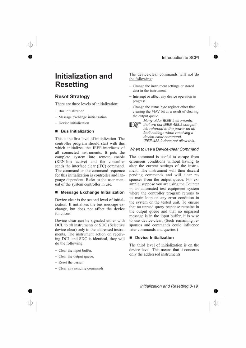
The device-clear commands will not dothe following:
– Change the instrument settings or stored
data in the instrument.
– Interrupt or affect any device operation in
progress.
– Change the status byte register other than
clearing the MAV bit as a result of clearing
the output queue.
Many older IEEE-instruments,that are not IEEE-488.2 compati-ble returned to the power-on de-fault settings when receiving adevice-clear command.IEEE-488.2 does not allow this.
When to use a Device-clear Command
The command is useful to escape fromerroneous conditions without having toalter the current settings of the instru-ment. The instrument will then discardpending commands and will clear re-sponses from the output queue. For ex-ample; suppose you are using the Counterin an automated test equipment systemwhere the controller program returns toits main loop on any error condition inthe system or the tested unit. To ensurethat no unread query response remains inthe output queue and that no unparsedmessage is in the input buffer, it is wiseto use device-clear. (Such remaining re-sponses and commands could influencelater commands and queries.)
Device Initialization
The third level of initialization is on thedevice level. This means that it concernsonly the addressed instruments.
Introduction to SCPI
Initialization and Resetting 3-19

The *RST Command
Use this command to reset a device. Itinitializes the device-specific functions inthe Counter.
The following happens when you use the*RST command:
– You set the Counter-specific functions to a
known default state. The *RST condition
for each command is given in the com-
mand reference chapters.
– You disable macros.
– You set the counter in an idle state (outputs
are disabled), so that it can start new oper-
ations.
The *CLS Command
Use this command to clear the status datastructures. See ‘Status Reporting system’in this chapter.
The following happens when you use the*CLS command:
– The instrument clears all event registers
summarized in the status byte register.
– It empties all queues, which are summa-
rized in the status byte register, except the
output queue, which is summarized in the
MAV bit.
3-20 Initialization and Resetting
Introduction to SCPI

Chapter 4
Programming
Examples

Introduction
Each program example in this chapter iswritten for IBM-PC compatible comput-ers equipped with the National Instru-ments PC-IIA. In addition to that, manyof the examples are written in both‘GW-BASIC’ and ‘C’.
Even if you do not have these interfaceboard or use these computer languages,look at the examples anyway. They giveyou a good insight on how to program theinstrument efficiently.
To be able to run these programswithout modification, the addressof your counter must be set to 10.
Example 1. Limit Testing
Example 2. REAL Data Format
Example 3. Frequency Profiling
Example 4. Fast Sampling
Example 5. Status Reporting
Example 6. Statistics, this example is only for
PM6680B and PM6681
4-2 Introduction
Programming Examples

GW-Basic for National
Instruments PC-IIA
Setting up the interface
All these programs start with a declaration containing three lines of setup informationfor the interface. This declaration must be merged with the programs prior to runningthem. The declaration is printed below, but it is also available as a file on the diskettesdelivered with your interface. The file name is DECL.BAS.
20 CLEAR ,60000! : IBINIT1=60000! : IBINIT2=IBINIT1+3 : BLOAD“bib.m”,IBINIT130 CALLIBINIT1(IBFIND,IBTRG,IBCLR,IBPCT,IBSIC,IBLOC,IBPPC,IBBNA,IBONL,IBRSC,IBSRE,IBRSV,IBPAD,IBSAD,IBIST,IBDMA,IBEOS,IBTMO,IBEOT, IBRDF,IBWRTF,IBTRAP,IBDEV,IBLN)40 CALLIBINIT2(IBGTS,IBCAC,IBWAIT,IBPOKE,IBWRT,IBWRTA,IBCMD,IBCMDA,IBRD,IBRDA,IBSTOP,IBRPP,IBRSP,IBDIAG,IBXTRC,IBRDI,IBWRTI,IBRDIA,IBWRTIA,IBSTA%,IBERR%,IBCNT%)
Programming Examples
GW-Basic for National Instruments PC-IIA, Setting Up the Interface 4-3

1. Limit Testing
This program uses limit testing to check that the frequency is above a preset value.
50 CNTNAME$ = “DEV10"60 CALL IBFIND (CNTNAME$, CNT%)70 ‘80 ‘90 ‘ —— Set continuous frequency measurement ——100 WRT$ = “*RST; *CLS; :FUNC ‘FREQ 1’; :INIT:CONT ON”110 CALL IBWRT (CNT%, WRT$)120 ‘130 ‘ —— Enable limit monitoring, limit 1 MHz ——140 WRT$ = “:CALC:LIM ON; LIM:UPP 1E6; UPP:STATE ON”150 CALL IBWRT (CNT%, WRT$)160 WRT$ = “:STAT:DREG0:ENAB 2; *SRE 1"170 CALL IBWRT (CNT%, WRT$)180 ‘190 ‘ —— Wait until the limit is passed ——200 PRINT “Waiting for limit to be passed”210 MASK% = &H800220 CALL IBWAIT (CNT%, MASK%)230 ‘240 ‘ —— Read status and device status register ——250 CALL IBRSP (CNT%, SPR%)260 ‘270 ‘ —— Read frequency ——280 WRT$ = “READ?”290 CALL IBWRT (CNT%, WRT$)300 MSG$ = SPACE$(255)310 CALL IBRD (CNT%, MSG$)320 PRINT “Frequency = ”; LEFT$(MSG$, IBCNT%)330 WRT$ = “:STAT:DREG0:EVEN?”340 CALL IBWRT (CNT%, WRT$)350 MSG$ = SPACE$(255)360 CALL IBRD (CNT%, MSG$)370 ‘380 ‘ —— Disable continuous measurement ——390 WRT$ = “:INIT:CONT OFF”400 CALL IBWRT (CNT%, WRT$)410 END
Programming Examples
4-4 GW-Basic for National Instruments PC-IIA, Setting Up the Interface

3. Frequency Profiling
Frequency profiling visualizes frequency variations for a certain time. This programgives an output file called:PROFILE.DAT. If this file is imported to a spreadsheet program, for instance Excel,you can create a graph like the one in the figure below.
50 ‘60 OPEN “O”, 1, “PROFILE.DAT”70 CNTNAME$ = “DEV10"80 CALL IBFIND (CNTNAME$, CNT%)90 ‘100 ‘110 ‘ —— Enable arming, etc. ——120 WRT$ = “:TRIG:COUN 1; :ARM:COUN 1; SOUR EXT4"130 CALL IBWRT(CNT%, WRT$)140 WRT$ = “:INP:LEV:AUTO ONCE150 CALL IBWRT(CNT%, WRT$)160 WRT$ = “:DISP:ENAB OFF; :ACQ:APER 1E-6"170 CALL IBWRT(CNT%, WRT$)180 ‘190 ARMDELAY = .0000002
Programming Examples
GW-Basic for National Instruments PC-IIA, Setting Up the Interface 4-5
Figure 4-1 This figure is the results of frequency profiling on a
sweep generator.

200 ‘210 ‘ ==== CAPTURE PROFILE =====220 ‘230 PRINT “Profiling”240 ‘250 FOR I=0 TO 999260 ‘ —— Set arming delay time --270 WRT$ = “:ARM:DEL” + STR$(ARMDELAY)280 CALL IBWRT(CNT%, WRT$)290 ‘300 ‘ —— Measure and read result --310 WRT$ = “READ?”320 CALL IBWRT(CNT%, WRT$)330 MSG$ = SPACE$(255)340 CALL IBRD(CNT%, MSG$)350 ‘360 ‘ —— Write arming delay time and result to file --370 PRINT#1, STR$(ARMDELAY), LEFT$(MSG$, INSTR(MSG$,
CHR$(10)))380 ‘390 ‘ —— Increase arming delay --400 ARMDELAY = ARMDELAY + .0000001410 NEXT I420 ‘430 WRT$ = “:DISP:ENAB ON”440 CALL IBWRT(CNT%, WRT$)450 ‘460 CLOSE 1470 END
Programming Examples
4-6 GW-Basic for National Instruments PC-IIA, Setting Up the Interface

4. Fast Sampling
This program makes a quick array measurement and stores the results in the internalmemory of the counter. Then it writes the results to a file called MEAS.DAT. Themeasurement results as a function of the samples can be visualized in a spreadsheetprogram such as Excel.
50 ‘60 OPEN “O”, 1, “MEAS.DAT”70 CNTNAME$ = “DEV10"80 CALL IBFIND (CNTNAME$, CNT%)90 ‘100 ‘110 ‘ —— Clear status ——120 WRT$ = “*CLS”130 CALL IBWRT(CNT%, WRT$)140 ‘150 ‘ —— Enable 1000 measurement with maximum speed ——160 WRT$ = “:TRIG:COUN 1000; :ARM:COUN 1"170 CALL IBWRT (CNT%, WRT$)180 WRT$ = “:INP:LEV:AUTO ONCE; :CAL:INT:AUTO OFF”190 CALL IBWRT (CNT%, WRT$)200 WRT$ = “:DISP:ENAB OFF; :INT:FORM PACKED”210 CALL IBWRT (CNT%, WRT$)220 WRT$ = “:ACQ:APER MIN; :AVER:STAT OFF”230 CALL IBWRT (CNT%, WRT$)240 ‘250 ‘ —— Enable SRQ on operation complete ——260 WRT$ = “*ESE 1; *SRE 32"270 CALL IBWRT (CNT%, WRT$)280 ‘290 ‘ —— Start measurement ——300 PRINT “Measuring”310 WRT$ = “INIT; *OPC”320 CALL IBWRT (CNT%, WRT$)330 ‘340 ‘ —— Wait for operation complete ——350 MASK = &H800360 CALL IBWAIT (CNT%, MASK)370 ‘380 ‘ —— Read status and event status register ——390 CALL IBRSP (CNT%, SPR%)400 WRT$ = “*ESR?”410 CALL IBWRT (CNT%, WRT$)420 MSG$ = SPACE$(255)430 CALL IBRD (CNT%, MSG$)
Programming Examples
GW-Basic for National Instruments PC-IIA, Setting Up the Interface 4-7

440 ‘450 PRINT “Fetching result”460 ‘470 FOR I=0 TO 999480 ‘ —— Fetch one result ——490 WRT$ = “FETCH?”500 CALL IBWRT (CNT%, WRT$)510 MSG$ = SPACE$(255)520 CALL IBRD (CNT%, MSG$)530 ‘540 ‘ —— Write result to file ——550 PRINT#1, I, LEFT$(MSG$, INSTR(MSG$, CHR$(10)))560 NEXT I570 ‘580 WRT$ = “:DISP:ENAB ON”590 CALL IBWRT(CNT%, WRT$)600 ‘610 CLOSE 1620 END
Programming Examples
4-8 GW-Basic for National Instruments PC-IIA, Setting Up the Interface

5. Status Reporting
This program sets up the status reporting for Service Request on ‘Message Available’and ‘Command’, ‘Execution’, or Query’ errors.
The program reads a command from the controller keyboard and sends it to the coun-ter, then it checks the status byte using Serial Poll. It determines the reason for ServiceRequest, and reads query responses and error messages.
50 CNTNAME$ = “DEV10"60 CALL IBFIND (CNTNAME$, CNT%)70 ‘80 ‘90 ‘ —— CLEAR STATUS ——100 WRT$ = “*cls”110 CALL IBWRT (CNT%, WRT$)120 ‘130 ‘ —— SET EVENT STATUS ENABLE ——140 ‘ Enable Command Error, Execution Error and Query Error150 WRT$ = “*ese 52"160 CALL IBWRT (CNT%, WRT$)170 ‘180 ‘ —— SET SERVICE REQUEST ENABLE ——190 ‘ Enable Service Request on Event Status and Message
Available200 WRT$ = “*sre 48"210 CALL IBWRT (CNT%, WRT$)220 ‘230 ‘ ======== MAIN LOOP =======================================240 WHILE 1250 ‘260 ‘ —— ENTER COMMAND STRING AND SEND TO COUNTER ——270 LINE INPUT “Enter command string (<CR> to end):”, CMD$280 IF CMD$ = “” GOTO 760290 CMD$ = CMD$300 CALL IBWRT (CNT%, CMD$)310 ‘ WAIT for execution320 FOR I=1 TO 1000330 CALL IBRSP (CNT%, SPR%)340 IF SPR% AND 16 THEN GOTO 380350 NEXT I360 ‘370 ‘ —— READ STATUS BYTE ——380 IF SPR% <> 0 THEN PRINT “Status byte = ”; SPR%390 ELSE GOTO 750400 ‘
Programming Examples
GW-Basic for National Instruments PC-IIA, Setting Up the Interface 4-9

410 ‘ —— CHECK MESSAGE AVAILABLE BIT ——420 WHILE SPR% AND 16430 PRINT “ Message available bit set”440 MSG$ = SPACE$(255)450 CALL IBRD (CNT%, MSG$)460 LFPOS = INSTR(MSG$, CHR$(10))470 IF LFPOS <> 0 THEN PRINT “Response = ” LEFT$(MSG$,
LFPOS)480 IF LFPOS = 0 THEN PRINT “Response = ”; MSG$490 CALL IBRSP (CNT%, SPR%)500 WEND510 ‘520 ‘ —— CHECK EVENT STATUS BIT ——530 IF NOT SPR% AND 32 GOTO 750540 PRINT “ Event status bit set”550 WRT$ = “*esr?”560 CALL IBWRT (CNT%, WRT$)570 ESR$ = SPACE$(255)580 CALL IBRSP (CNT%, SPR%)590 CALL IBRD (CNT%, ESR$)600 ESR% = VAL(ESR$)610 IF ESR% AND 32 THEN PRINT “ Command error”620 IF ESR% AND 16 THEN PRINT “ Execution error”630 IF ESR% AND 4 THEN PRINT “ Query error”640 ‘650 ‘ —— READ ERROR MESSAGES ——660 WRT$ = “syst:err?”670 ERRMESS$ = SPACE$(255)680 CALL IBWRT (CNT%, WRT$)690 CALL IBRD (CNT%, ERRMESS$)700 WHILE NOT INSTR(ERRMESS$, “No error”) <> 0710 PRINT LEFT$(ERRMESS$, INSTR(ERRMESS$, CHR$(10)))720 CALL IBWRT (CNT%, WRT$)730 CALL IBRD (CNT%, ERRMESS$)740 WEND750 WEND760 PRINT “PROGRAM TERMINATED”770 END
Programming Examples
4-10 GW-Basic for National Instruments PC-IIA, Setting Up the Interface
6. Statistics
(Only for PM6680B and PM6681)
In this example, the counter makes 10000 measurements and uses the statistical func-tions to determine MAX, MIN, MEAN, and Standard Deviation. All four results aresent to the controller.
50 CNTNAME$ = “DEV10"60 CALL IBFIND (CNTNAME$, CNT%)70 ‘80 ‘90 WRT$ = “*RST; *CLS; *SRE 16; :FUNC ‘Freq 1’; :ACQ:APER MIN”100 CALL IBWRT (CNT%, WRT$)110 WRT$ = “:INP:LEV:AUTO Off”120 CALL IBWRT (CNT%, WRT$)130 ‘140 ‘ —— Enable statistics on 10000 measurements ——150 WRT$ = “:CALC:AVER:STAT ON; COUN 10000"160 CALL IBWRT (CNT%, WRT$)170 ‘180 ‘ ==== Start measurement ====190 WRT$ = “:Init; *OPC?”200 CALL IBWRT (CNT%, WRT$)210 ‘220 ‘ —— Wait for operation complete (MAV) ——230 PRINT “WAITING FOR MEASUREMENT TO GET READY”240 MASK% = &H800250 CALL IBWAIT (CNT%, MASK%)260 ‘270 ‘ —— Read status and response ——280 CALL IBRSP (CNT%, SPR%)290 MSG$ = SPACE$(255)300 CALL IBRD (CNT%, MSG$)310 ‘320 ‘ —— Maximum ——330 WRT$ = “:CALC:AVER:TYPE MAX; :CALC:IMM?”340 CALL IBWRT (CNT%, WRT$)350 MSG$ = SPACE$(255)360 CALL IBRD (CNT%, MSG$)370 PRINT “MAXIMUM = ”; LEFT$(MSG$, IBCNT%)380 ‘390 ‘ —— Minimum ——400 WRT$ = “:CALC:AVER:TYPE MIN; :CALC:IMM?”410 CALL IBWRT (CNT%, WRT$)420 MSG$ = SPACE$(255)
Programming Examples
GW-Basic for National Instruments PC-IIA, Setting Up the Interface 4-11

430 CALL IBRD (CNT%, MSG$)440 PRINT “MINIMUM =”; LEFT$(MSG$, IBCNT%)450 ‘460 ‘ —— Mean ——470 WRT$ = “:CALC:AVER:TYPE MEAN; :CALC:IMM?”480 CALL IBWRT (CNT%, WRT$)490 MSG$ = SPACE$(255)500 CALL IBRD (CNT%, MSG$)510 PRINT “MEAN =”; LEFT$(MSG$, IBCNT%)520 ‘530 ‘ —— Standard deviation ——540 WRT$ = “:CALC:AVER:TYPE SDEV; :CALC:IMM?”550 CALL IBWRT (CNT%, WRT$)560 MSG$ = SPACE$(255)570 CALL IBRD (CNT%, MSG$)580 PRINT “STANDARD DEVIATION =”; LEFT$(MSG$, IBCNT%)590 END
Programming Examples
4-12 GW-Basic for National Instruments PC-IIA, Setting Up the Interface

‘C’ for National Instruments
PC-IIA
Programming Examples
‘C’ for National Instruments PC-IIA

1. Limit Testing
This program uses limit testing to check that the frequency is above a preset value.
#include “decl.h”#include <stdio.h>#include <process.h>main ()int Counter, Status, i;char InString[80];
Counter = ibfind(“DEV10");
/*Set continuous frequency measurement*/ibwrt(Counter, “*RST; *CLS; :FUNC ‘Freq 1’; :INIT:CONT ON”,
41);
/*Enable limit monitoring, limit 1 MHz*/ibwrt(Counter, “:CALC:LIM ON; LIM:UPP 1E6; UPP:STAT ON”, 38);ibwrt(Counter, “:STAT:DREG0:ENAB 2; *SRE 1", 26);
/*Wait until the limit is passed*/printf(“Waiting for limit to be passed\n”);ibwait(Counter, RQS);
/**Read status and device status register**/ibrsp(Counter, &Status);ibwrt(Counter, “:STAT:DREG0:EVEN?”, 17);ibrd(Counter, InString, 80);
/*Read frequency**/ibwrt(Counter, “READ?”, 5);ibrd(Counter, InString, 80);InString[ibcnt] = ‘\0’;printf(“Frequency = %s\n”, InString);
/*Disable continuous measurement*/ibwrt(Counter, “:INIT:CONT OFF”, 14);
exit(0);
Programming Examples
4-14 ‘C’ for National Instruments PC-IIA, Limit Testing

2. REAL Data Format
This program uses the REAL data format to speed up the measurement.
/* IEEE 488.2 binary real format follows the ‘little-endian’ format with themost-significant byte first and the least-significant byte last. Intel processors use the‘big-endian’ format, with the least-significant byte first, so we have to reverse the byteorder of the incoming block when running on a PC (Intel processor).
#include “decl.h”#include <stdio.h>#include <process.h>#include <conio.h>main ()int Counter, i;char InString[80];double DoubleFreq;Counter = ibfind(“DEV10");
/*Make the counter output it’s result in real format*/ibwrt(Counter, “:FORM REAL”, 10);
/*Make continuous measurements until a key is hit*/do
/*Make a measurement and read the result*/ibwrt(Counter, “READ?”, 5);ibrd(Counter, InString, 80);
/*Assign the bytes 3...10 of InString to DoubleFreq bytes7...0.The format of InString is #18******** , where “********”represents the value.*/for (i=0; i<8; i++)((unsigned char *)&DoubleFreq)[7-i] = InString[3+i];
/*Print the result*/printf(“%le\n”, DoubleFreq);
while (!kbhit());
/*Restore ascii output format*/ibwrt(Counter, “:FORM ASCII”, 11);
exit(0);
Programming Examples
‘C’ for National Instruments PC-IIA, Real Data Format 4-15

3. Frequency Profiling
Frequency profiling visualizes frequency variations for a certain time. This programgives an output file called:PROFILE.DAT. If this file is imported to a spreadsheet program, such as Excel, youcan create a graph like the one in the figure below.
#include “decl.h”#include <stdio.h>#include <process.h>#include <string.h>
main ()
int Counter, i;char ArmString[80],
InString[80];double ArmDelay;FILE *ofp;
if (ofp = fopen(“PROFILE.DAT”, “w”)) Counter = ibfind(“DEV10");
/*Enable arming, etc.*/ibwrt(Counter, “:TRIG:COUN 1; :ARM:COUN 1", 25);
Programming Examples
4-16 ‘C’ for National Instruments PC-IIA, Frequency Profiling
Figure 4-2 This figure is the results of frequency profiling on a
sweep generator.

ibwrt(Counter, “:INP:LEV:AUTO ONCE”, 18);ibwrt(Counter, “:DISP:ENAB OFF; :ACQ:APER 1E-6", 30);
ArmDelay=200e-9;
/*CAPTURE PROFILE*/
Printf(”Profiling”);
for (i=0; i<1000; i++) /*Set arming delay time*/sprintf(ArmString, “:ARM:DEL %le”, ArmDelay);ibwrt(Counter, ArmString, strlen(ArmString));
/*Measure and read result*/ibwrt(Counter, “READ?”, 5);ibrd(Counter, InString, 80);InString[ibcnt] = ‘\0’;
/*Write arming delay time and result to file*/fprintf(ofp, “%le, %s”, ArmDelay, InString);
/*Increase arming delay*/ArmDelay += 100e-9;
ibwrt(Counter, “:DISP:ENAB ON”, 13);
/*Close file*/Fclose(ofp);
elseprintf(“CANT OPEN FILE”);
exit(0);
Programming Examples
4-17 ‘C’ for National Instruments PC-IIA, Frequency Profiling

4. Fast Sampling
This program makes a quick array measurement and stores the results in the internalmemory of the counter. Then it writes the results to a file called MEAS.DAT. Themeasurement results as a function of the samples can be visualized in a spreadsheetprogram, such as Excel.
#include “decl.h”#include <stdio.h>#include <process.h>#include <string.h>
main ()
int Counter, Status, i;char InString[80];FILE *ofp;
if (ofp = fopen(“MEAS.DAT”, “w”))
Counter = ibfind(“DEV10");
/*Clear status*/ibwrt(Counter, “*CLS”, 4);
/*Enable 1000 measurement with maximum speed*/ibwrt(Counter, “:TRIG:COUN 1000; :ARM:COUN 1", 28);ibwrt(Counter, “:INP:LEV:AUTO ONCE; :CAL:INT:AUTO OFF”, 37);ibwrt(Counter, “:DISP:ENAB OFF; :INT:FORM PACKED”, 32);ibwrt(Counter, “:ACQ:APER MIN; :AVER:STAT OFF”, 32);
/**Enable SRQ on operation complete**/ibwrt(Counter, “*ESE 1; *SRE 32", 15);
/*Start measurement*/printf(“Measuring\n”);ibwrt(Counter, “INIT; *OPC”, 10);
/*Wait for operation complete*/ibwait(Counter, RQS);
/**Read status and event status register**/ibrsp(Counter, &Status);ibwrt(Counter, “*ESR?”, 5);
Programming Examples
4-18 ‘C’ for National Instruments PC-IIA, Fast Sampling

ibrd(Counter, InString, 80);printf(“Fetching result”);
for (i=0; i<1000; i++) /*Fetch one result*/ibwrt(Counter, “FETCH?”, 6);ibrd(Counter, InString, 80);InString[ibcnt] = ‘\0’;
/*Write result to file*/fprintf(ofp, “%d, %s”, i, InString);
ibwrt(Counter, “:DISP:ENAB ON”, 13);
/*Close file*/Fclose(ofp);
elseprintf(“CANT OPEN FILE”);
exit(0);
Programming Examples
‘C’ for National Instruments PC-IIA, Fast Sampliing 4-19

6. Statistics
(Only for PM6680B and PM6681)
In this example, the counter makes 10000 measurements and uses the statistical func-tions to determine MAX, MIN, MEAN, and Standard Deviation. All four results aresent to the controller.
#include “decl.h”#include <stdio.h>#include <process.h>
main ()
int Counter, Status, i;char InString[80];
Counter = ibfind(“DEV10");ibwrt(Counter, “*CLS; *SRE 16", 13);ibwrt(Counter, “*RST; :FUNC ‘Freq 1’; :ACQ:APER MIN”, 38);ibwrt(Counter, “:INP:LEV:AUTO OFF”, 17);
/*Enable statistics on 10000 measurements*/ibwrt(Counter, “:CALC:AVER:STAT ON; COUN 10000", 30);ibwrt(Counter, “:TRIG:COUN 10000", 16);
/*Start measurement*/ibwrt(Counter, “:Init; *OPC?”, 12);
/*Wait for operation complete (MAV)*/printf(“Waiting for measurement to get ready\n”);ibwait(Counter, RQS);
/**Read status and response**/ibrsp(Counter, &Status);ibrd(Counter, InString, 80);
/*Read maximum value**/ibwrt(Counter, “:CALC:AVER:TYPE MAX; :CALC:IMM?”, 31);
ibrd(Counter, InString, 80);InString[ibcnt] = ‘\0’;printf(“Maximum = %s\n”, InString);
Programming Examples
4-20 ‘C’ for National Instruments PC-IIA, Statistics

/*Read minimum value*/ibwrt(Counter, “:CALC:AVER:TYPE MIN; :CALC:IMM?”, 31);ibrd(Counter, InString, 80);InString[ibcnt] = ‘\0’;printf(“Minimum = %s\n”, InString);
/*Read mean value*/ibwrt(Counter, “:CALC:AVER:TYPE MEAN; :CALC:IMM?”, 32);ibrd(Counter, InString, 80);InString[ibcnt] = ‘\0’;printf(“Mean = %s\n”, InString);
/*Read standard deviation value*/ibwrt(Counter, “:CALC:AVER:TYPE SDEV; :CALC:IMM?”, 32);ibrd(Counter, InString, 80);InString[ibcnt] = ‘\0’;printf(“Standard deviation = %s\n”, InString);
exit(0);
Programming Examples
‘C’ for National Instruments PC-IIA, Statistics 4-21

This side is intentionally left blank.
Programming Examples
4-22 ‘C’ for National Instruments PC-IIA

Chapter 5
Instrument Model

Introduction
The figure below shows how the instru-ment functions are categorized. This in-strument model is fully compatible withthe SCPI generalized instrument model.
The generalized SCPI instrument model,contains three major instrument catego-ries as shown in the following table:
Function Instrument
type
Examples
Signal ac-quisition
Sense in-struments
Voltmeter, Os-cilloscope,Counter
Signalgenera-tion
Source in-struments
Pulse genera-tor, Power sup-ply
Signalrouting
Switch in-struments
Scaners,(de)-multiplexers
An instrument may use a combination ofthe above functions. The CNT-8X coun-ters belong to the signal acquisition cate-gory, and only that category is describedin this manual.
The instrument model in Figure 5-1 de-fines where elements of the counter lan-guage are assigned in the commandhierarchy. The major signal function ar-eas are shown broken into blocks. Eachof these blocks are major commandsub-trees in the counter command lan-guage.
The instrument model also shows howmeasurement data and applied signalsflow through the instrument. The modeldoes not include the administrative dataflow associated with queries, commands,performing calibrations etc.
5-2 Introduction
Instrument Model
A
B
C
E
1
2
3
4GPIB
MEMoryTRIGger
OUTPut
FORMat
DISPlay
Measurement Function
Inputs Channels
Figure 5-1 CNT-8X Instrument model. Note that Input B (channel 2) is not avail-
able on PM6685.
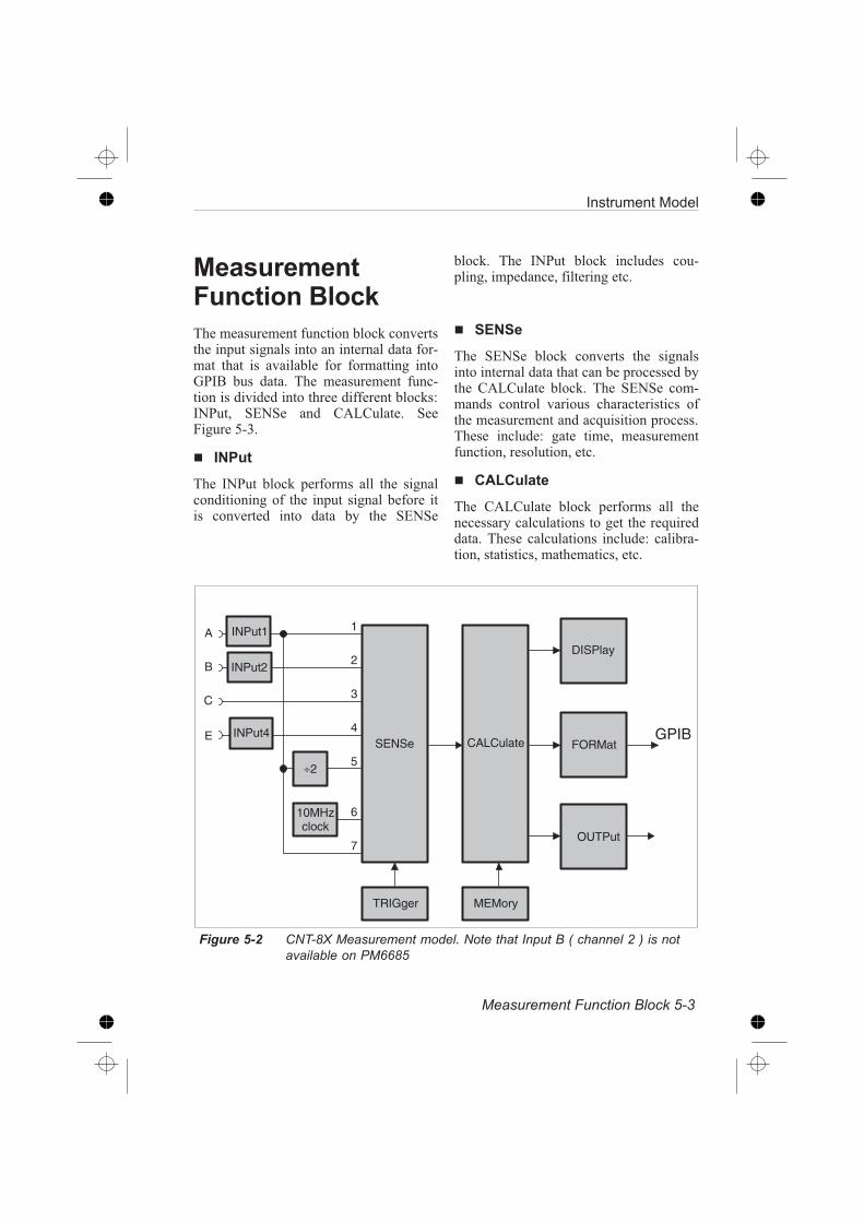
MeasurementFunction Block
The measurement function block convertsthe input signals into an internal data for-mat that is available for formatting intoGPIB bus data. The measurement func-tion is divided into three different blocks:INPut, SENSe and CALCulate. SeeFigure 5-3.
INPut
The INPut block performs all the signalconditioning of the input signal before itis converted into data by the SENSe
block. The INPut block includes cou-pling, impedance, filtering etc.
SENSe
The SENSe block converts the signalsinto internal data that can be processed bythe CALCulate block. The SENSe com-mands control various characteristics ofthe measurement and acquisition process.These include: gate time, measurementfunction, resolution, etc.
CALCulate
The CALCulate block performs all thenecessary calculations to get the requireddata. These calculations include: calibra-tion, statistics, mathematics, etc.
Instrument Model
Measurement Function Block 5-3
10MHzclock
A
B
C
E
÷2
1
2
3
4
5
6
7
GPIBINPut4SENSe CALCulate
MEMoryTRIGger
OUTPut
FORMat
DISPlay
INPut2
INPut1
Figure 5-2 CNT-8X Measurement model. Note that Input B ( channel 2 ) is not
available on PM6685

Other Subsystems
In addition to the major functions (sub-systems), there are several other subsys-tems in the instrument model.
The different blocks have the following
functions.
CALibration
This subsystem controls the calibration ofthe interpolators used to increase the res-olution of the CNT-8X counters.
DISPlay
Commands in this subsystem controlwhat data is to be present on the displayand whether the display is on or off.
FORMat
The FORMat block converts the internaldata representation to the data transferredover the external GPIB interface. Com-mands in this block control the data typeto be sent over the external interface.
MEMory
The MEMory block holds macro and in-strument state data inside the counter.
OUTPut
This subsystem controls the analog out-put available in the CNT-8X counters.
STATus
This subsystem can be used to get infor-mation about what is happening in the in-strument at the moment.
Synchronization
This subsystem can be used to synchro-nize the measurements with the control-ler.
SYSTem
This subsystem controls some system pa-rameters like timeout.
TEST
This subsystem tests the hardware andsoftware of the counter and reports errors.
TRIGger
The trigger block provides the counterwith synchronization capability with ex-ternal events. Commands in this blockcontrol the trigger and arming functionsof the Timer/ Counter.
Order of Execution
– All commands in CNT-8X counters are se-
quential, i.e., they are executed in the same
order as they are received.
– If a new measurement command is re-
ceived when a measurement is already in
progress, the measurement in progress will
be aborted unless XWAI is used before the
command.
5-4 Other Subsystems
Instrument Model

MEASurementFunction
In addition to the subsystems of the in-strument model, which controls the in-strument functions, SCPI hassignal-oriented functions to obtain mea-surement results. This group of MEASurefunctions has a different level of compati-bility and flexibility. The parameters usedwith commands from the MEASuregroup describe the signal you are going tomeasure. This means that the MEASurefunctions give compatibility between in-struments, since you don’t need to know
anything about the instrument you are us-ing. See Figure 5-3.
MEASure?
This is the most simple command to use,but it does not offer much flexibility. TheMEASure? query lets the counter config-ure itself for an optimal measurement,start the data acquisition, and return theresult.
CONFigure; READ?
The CONFigure command makes thecounter choose an optimal setting for thespecified measurement. CONFiguremay cause any device setting to change.
Instrument Model
MEASurement Function 5-5
10MHzclock
A
B
C
E
÷2
1
2
3
4
5
6
7
GPIB
INPut1
INPut2
INPut4SENSe CALCulate
MEMory
OUTPut
FORMat
DISPlay
TRIGger
READ?CONFigure
MEASure?
FETch?
Figure 5-3 CNT-8X Measurement Function
Note that Input B (channel 2) is not available on PM6685.

READ? starts the acquisition and returnsthe result.
This sequence does the same as the MEA-Sure command, but now it is possible toinsert commands between CONFigureand READ? to adjust the setting of a par-ticular function (called fine tuning). Forinstance, you can set an input attenuatorat a required value.
CONFigure; INITiate;FETCh?
The READ? command can be dividedinto the INITiate command, which startsthe measurement, and the FETCh? com-mand, which requests the instrument toreturn the measuring results to the con-troller.
Versatility of Measurement Com-
mands
MEASure? Simple to use,, fewadditional possibili-ties.
CONFigure
READ?
Somewhat moredifficult,, but someextra possibilities.
CONFigure
INITiate
FETCh?
Most difficult touse,, but many ex-tra features.
5-6 MEASurement Function
Instrument Model

Chapter 6
Using the
Subsystems

Introduction
Although SCPI is intended to be self ex-planatory, we feel that some hints andtips on how to use the different subsys-tems may be useful. This chapter does
not explain each and every command,but only those for which we believe extraexplanations are necessary.
6-2
Using the Subsystems

Calculate Subsystem
The calculate subsystem processes themeasuring results. Here you can recalcu-late the result using mathematics, makestatistics (not PM6685) and set upper andlower limits for the measuing result thatthe counter itself monitors and alerts youwhen the limits are exceeded.
Mathematics
The mathematic functions are the same ason the front panel.
Statistics
The PM6680B and PM6681 can calculateand display the MIN, MAX, MEAN andstandard deviation of a given number ofsamples. The statistic functions are thesame as on the front panel.
Limit Monitoring
Limit monitoring makes it is possible toget a service request when the measure-ment value falls below a lower limit orrises above an upper limit. Two statusbits are defined to support limit monitor-ing. One is set when the results aregreater than the UPPer limit, the other isset when the result is less than theLOWer limit. The bits are enabled usingthe standard *SRE command and:STAT:DREG0:ENAB. Using both thesebits, it is possible to get a service requestwhen a value passes out of a band (UPPer is set at the upper band border andLOWer at the lower border) OR when ameasurement value enters a band(LOWer set at the upper band border andUPPer set at the lower border).Turning the limit monitoring calculationson/off will not influence the status regis-ter mask bits which determine whether ornot a service request will be generatedwhen a limit is reached. Note that the cal-culate subsystem is automatically enabledwhen limit monitoring is switched on.This means that other enabled calculatesub-blocks are indirectly switched on.
Using the Subsystems
Calculate Subsystem 6-3

Calibration Subsystem
The interpolators used to increase the res-olution of the measurement result in thecounter must be calibrated to maintain thehighest possible accuracy of the counter.
The calibration method of the PM6681differs from the method used inPM6680B and PM6685.
PM6680B, PM6685
The intepolators are automatically cali-brated before each measurement. Thisprocedure takes only a fraction of a sec-ond, but to increase speed, you can turnoff the auto calibration.
PM6681
In PM6681, the interpolators are factorycalibrated. Calibration must be performedonly after repair and can be performed atyour local Service centers.
If the calibration is lost for any reason,the counter will show ZCAL. LOSTZ .
By pressing PRESET you can bypass thismessage and use the counter anyway,however you must press the front panelkey. No bus command takes you past thiserror message.
This is so that you cannot bypass themessage by mistake, and run a test sys-tem without a calibrated instrument.
6-4 Calibration Subsystem
Using the Subsystems

Configure Function
The CONFigure command sets up thecounter to make the same measurementsas the MEASure query, but without initi-ating the measurement and fetching theresult. Use configure when you want to
change any parameters before making themeasurement.
Read more about Configure under MEA-Sure.
Using the Subsystems
Configure Function 6-5

Format Subsystem
Time StampReadout Format
It is not trivial to decide how timestamped measurements are to be pre-sented on the bus. If the ‘ADIF’ formatdefined by SCPI is adopted, it should beadopted for all data readout, and switchedon and off by the already standardized:FORMat:DINTerchange command. Thisformat covers the appropriate readout for-mat for time stamped measurements well,so when it is selected as output format,there is not any problem. But the usermay still decide not to use the ADIF for-mat, so we need a solution to the readoutproblem whether or not we decide to im-plement ADIF. The chosen one is as fol-lows:
For :FETCh:SCALar?, :READ:SCALar?and :MEASure:SCALar?, the readoutwill consist of two values instead of one.
The first will be the measured value, andthe next one will be the timestamp value,given in seconds in the NR2 formatddd.ddddddddd (12 digits).
In :FORMat ASCii mode, the result willbe given as a floating-point number (NR3format) followed by integers (NR1 for-mat). In :FORMat REAL mode, the resultwill be given as an eight-byte block con-taining the floating-point measured value,followed by a four-byte block containingthe integer timestamp count, where eachcount represents 125 nanoseconds.
When doing readouts in array form, with:FETCh :ARRay?, :READ :ARRay? or:MEASure :ARRay?, the response willconsist of alternating measurement valuesand timestamp values, formatted the sameway as for scalar readout. All values willbe separated by commas.
6-6 Format Subsystem
Using the Subsystems

Input Subsystems
PM6685
Using the Subsystems
Input Subsystems 6-7
INP:IMP 1E6
INP:SLOP POS
INP:SLOP NEG
INP:FILT OFF
INP:FILT ON
A 1
INP:IMP 50
0V
Trigger points
Reset points
INP:HYST <value in Volt>
t
INP:LEV <value in Volt>
Comparator
Figure 6-1 Summary of PM6685 input amplifier settings.

PM6680B/PM6681
Using the Subsystems
6-8 Input Subsystems
INP:IMP 1E6
INP:COUP AC
INP:COUP DC
INP:ATT 1 INP:ATT 10
INP:SLOP POS
INP:SLOP NEG
INP:FILT OFF
INP:FILT ON
INP2:COMM ON
INP2:COMM OFF
INP2:IMP 1E6
INP2:ATT 1 INP2:ATT 10
INP2:COUP AC
INP2:COUP DC INP2:SLOP POS
INP2:SLOP NEG
B
A 1
2
INP4:SLOP POS
INP4:SLOP NEG
4E
INP2:IMP 50
INP:IMP 50
Figure 6-2 Summary of PM6680B / PM6681 input amplifier settings.

Measurement Function
The Measure function group has a differ-ent level of compatibility and flexibilitythan other commands. The parametersused with commands from the Measuregroup describe the signal you are going tomeasure. This means that the Measurefunctions give compatibility between in-struments, since you don’t need to knowanything about the instrument you are us-ing.
MEASure?
This is the most simple query to use, butit does not offer much flexibility. TheMEASure? query lets the instrument con-figure itself for an optimal measurement,starts the data acquisition, and returns theresult.
Example:
SEND→ MEASure:FREQ?
This will execute a frequency measurementand the result will be sent to the controller.The instrument will select a setting for thispurpose by itself, and will carry out the re-quired measurement as “well” as possible;moreover, it will automatically start themeasurement and send the result to thecontroller.You may add parameters to give more
details about the signal you are going tomeasure, for example:
SEND→ MEASure:FREQ?20MHz,1
Where: 20 MHz is the expected value,which can, of course, also be sent as20E6, and 1 is the required resolution.(1 Hz)
Also the channel numbers can be speci-fied, for example:
SEND→ MEASure:FREQ?(@3)
SEND→ MEASure:FREQ?20E6,1,(@1)
CONFigure; READ?
The CONFigure command causes the in-strument to choose an optimal setting forthe specified measurement. CONFiguremay cause any device setting to change.READ? starts the acquisition and returnsthe result.
This sequence operates in the same wayas the MEASure command, but now it ispossible to insert commands betweenCONFigure and READ? to fine tune thesetting of a particular function. For exam-ple, you can change the input impedance
from 1 MΩ to 50 Ω.
Using the Subsystems
Measurement Function 6-9

Example:
SEND→ CONFigure:FREQ2E6,1
2E6 is the expected value1 is the required resolution (1Hz)
SEND→ INPut:IMPedance50OHM
Sets input impedance to 50 Ω
SEND→ READ?
Starts the measurement and returns theresult.
CONFigure;INITiate;FETCh?
The READ? command can be dividedinto the INITiate command, which startsthe measurement, and the FETCh? com-mand, which requests the instrument toreturn the measuring results to the con-troller.
Example:
SEND→ CONFigure:FREQ20E6,1
20E6 is the expected signal value1 is the required resolution
SEND→ INPut:IMPedance1E6
Sets input impedance to 1 MΩ
SEND→ INITiate
Starts measurement
SEND→ FETCh?
Fetches the result
Versatility of measurement com-
mands
MEASure? Simple to use, few addi-tional possibilities.
CONFigureREAD?
Somewhat more difficult,but some extra possibili-ties.
CONFigureINITiateFETCh?
Most difficult to use, butmany extra features.
6-10 Measurement Function
Using the Subsystems

Output Subsystem
The analog output is turned off as a de-fault. You turn it on/off and set the scal-ing factor under ANALOG OUT in theaux menu.
Scaling Factor
The scaling factor has two functions:
– Its exponent selects which digits to output
on the analog output.
– Its value sets what reading should represent
full scale.
As default, the scaling factor is 1 (1E0).This means that the full scale value is0.999 and the analog output converts thefraction (digits to the right of the decimalpoint) to a voltage.
The scaling factor should be:
Scaling factorfull scale value
1
where full scale value is the value forwhich you want the analog output to out-put its maximum voltage (5 V).
Example:
– Take a measurement result, for instance:
12.34567890 E+6 Hz
– Represent this result without exponent:
12345678.90 Hz
– Multiply this value with the scaling factor,
for instance 0.001.
12345.67890
– Take the fractional part of the result:
.67890
Using the Subsystems
Output Subsystem 6-11
Ω Ω Ω Ω
! " # Ω $ Ω
Ω
% * ) , - + . 9 E 2 1 3 # $ B 0 J = 3 C 2 # % , 4 3 9 E # : 0 B 3 . = F 0 : 9 + !
$ ( $
. 0 B + = < 9 & 5 # 2 9 # : 0 B 3 . = F 0 : 9 + ! 0 . 1 2 I $ + . 2 . 9
# : 0 B 3 . = F 0 : 9 + !
# : 0 B 3 . = F 0 : 9 + ! (
: 0 B 3 . = F 0 : 9 + ! # 2 B 2 : 9 # F < B B # : 0 B 2 C 0 B < 2
: 0 B 3 . = 2 I $ + . 2 . 9 " + C 2 # 3 . # 2 ! 9 3 + . $ + 3 . 9
Figure 6-3 The analog output func-
tion.

– This is the value that will determine the
output voltage; .00 will give 0 V and .99
will give 5 V. This means that the reading
will give:
.67890*5=3.3945 V.
This is ouput as 3.38 V due to the 0.02 V
resolution of the analog output.
Resolution
The analog output range is 0 to 5 V in250 steps, so one step is 0.02 V. If thescaling factor is 1, one such step is takeneach time the display changes withX.004, and if the scaling factor is 4, onestep is taken each time the displaychanges with X.001.
The X in the above paragraph can be anydigit and does not influence the outputvoltage. If the display changes from0.996 to 1.000, the voltage drops from4.98 V to 0V. If the display value in-creases further, the output voltage starts
to increase again; see .
6-12 Output Subsystem
Using the Subsystems
2 F 0 < B 9 # : 0 B 3 . = F 0 : 9 + ! &
: 0 B 3 . = F 0 : 9 + ! & *
Figure 6-4 To use the shown deci-
mal point as reference,
set the exponent of the
scaling factor to the
same value as the expo-
nent of the measurement
result but with opposite
sign.
4.98 V
0.00V
0.00
0
0.9961.000
1.9962.000
4.98 V
0.00V0.000
20mV
20mV
0.24
90.
499 0.
500
0.001
0.25
0
0.004
Output voltage
valueDisplayed
Output voltage
valueDisplayed
Scaling factor 1
Scaling factor 4
Figure 6-5 Output voltage versus
displayed value for two
different scaling factors.
Same exponent, opposite sign

Sense Command
Subsystems
Depending on application, you can selectdifferent input channels and input charac-teristics.
Switchbox
In automatic test systems, it is difficult toswap BNC cables when you need to mea-sure on several measuring points. WithPM6680B/1 you can select from threedifferent basic inputs (A, B and E), onwhich the counter can measure directlywithout the need for external switchingdevices. With PM6685 you can selectfrom two different basic inputs (A and E).
Prescaling
For all measuring functions except fre-quency, the maximum input A frequencyis 160 MHz.
To extend the range for frequency mea-surements, PM6680B and PM6685 candivide (scale) the input A frequency bytwo, while PM6681 scales by four.
When using channel 1, the counter auto-matically selects this scaling factor whenmeasuring FREQ A, giving 300 MHzmax frequency for PM6681 and PM6685,and 225 MHz for PM6680B.
For all other measuring functions, and forfrequency if you select negative slope,the counter does not divide the signal andthe max repetition rate is 160 MHz.
Using the Subsystems
Sense Command Subsystem 6-13

Status Subsystem
Introduction
Status reporting is a method to let thecontroller know what the counter is do-ing. You can ask the counter what statusit is in whenever you want to know.
You can select some conditions in thecounter that should be reported in the Sta-tus Byte Register. You can also select ifsome bits in the Status Byte should gen-erate a Service Request (SRQ).(An SRQ is the instrument’s way to callthe controller for help.)
Status Reporting Model
The Status Structure
The status reporting model used byCNT-8X is standardized in IEEE 488.2and SCPI, so you will find similar statusreporting in most modern instruments.Figure 6-6 shows an overview of thecomplete CNT-8X status register struc-ture. It has four registers, two queues, anda status byte:
– The Standard Event Register reports the
standardized IEEE 488.2 errors and condi-
tions.
– The Operation Status Register reports the
status of the CNT-8X measurement cycle
(see also ARM-TRIG model, page 6-27).
– The Questionable Data Register reports
when the output data from the CNT-8X
may not be trusted.
– The Device Register 0 reports when the
measuring result has exceeded prepro-
grammed limits.
– The Output Queue status reports if there
is output data to be fetched.
– The Error Queue status reports if there
are error messages available in the error
queue.
– The Status Byte contains eight bits. Each
bit shows if there is information to be
fetched in the above described registers
and queues of the status structure.
Using the Registers
Each status register monitors several con-ditions at once. If something happens toany one of the monitored conditions, asummary bit is set true in the Status ByteRegister.
Enable registers are available so that youcan select what conditions should be re-
6-14 Status Subsystem
Using the Subsystems

ported in the status byte, and what bits inthe status byte should cause SRQ.
A register bit is TRUE, i.e., some-thing has happened, when it isset to 1. It is FALSE when set to0.
Note that all event registers and the statusbyte records positive events. That is whena condition changes from inactive to ac-
tive, the bit in the event register is settrue. When the condition changes fromactive to inactive, the event register bitsare not affected at all.
When you read the contents of a register,the counter answers with the decimal sumof the bits in the register.
Using the Subsystems
Status Subsystem 6-15
+ = 3 : 0 B
. 0 > B 2 2 = 3 # 9 2 !
C 2 . 9 2 = 3 # 9 2 !
!
2 ! C 3 : 2 2 G < 2 # 9 . 0 > B 2
+ = 3 : 0 B
9 0 9 < # J 9 2 2 = 3 # 9 2 !
+ = 3 : 0 B
+ . 1 3 9 3 + . 2 = 3 # 9 2 !
+ . 1 3 9 3 + . 2 = 3 # 9 2 !
" !
! # $ % & !
" & ' !
(*)
"&&
$&%&"&&
. 0 > B 2 2 = 3 # 9 2 !
C 2 . 9 2 = 3 # 9 2 !
. 0 > B 2 2 = 3 # 9 2 !
C 2 . 9 2 = 3 # 9 2 !
+ = 3 : 0 B
C 2 . 9 2 = 3 # 9 2 !
. 0 > B 2 2 = 3 # 9 2 !
+ = 3 : 0 B
Figure 6-6 CNT-8X Status register structure.

Example:
The counter answers 40 when you ask forthe contents of the Standard Event StatusRegister.
– Convert this to binary form. It will give
you 101000.
– Bit 5 is true showing that a command error
has occurred.
– Bit 3 is also true, showing that a device de-
pendent error has occurred.
Use the same technique when you pro-gram the enable registers.
– Select which bits should be true.
– Convert the binary expression to decimal
data.
– Send the decimal data to the instrument.
Clearing/Setting all bits
– You can clear an enable register by pro-
gramming it to zero. You can set all bits
true in a 16-bit event enable register by
programming it to 32767 (bit 16 not used).
– You set all bits true in 8-bit registers by
programming them to 255 (Service Re-
quest Enable and Standard Event Enable.)
Using the Queues
The two queues, where CNT-8X storesoutput data and error messages, may con-tain data or be empty. Both these queueshave their own status bit in the StatusByte. If this bit is true there is data to befetched.
When the controller reads data, it willalso remove the data from the queue. Thequeue status bit in the status byte will re-main true for as long as the queue holds
one or more data bytes. When the queueis empty, the queue status bit is set false.
Status of the Output Queue (MAV)
The MAV (message available) queue sta-tus message appears in bit 4 of the statusbyte register. It indicates if there are bytesready to be read over the GPIB in theGPIB output queue of the instrument.The output queue is where the formatteddata appears before it is transferred to thecontroller.
The controller reads this queue by ad-dressing the instrument as a talker. Thecommand to do this differs between dif-ferent programming languages. Examplesare IOENTERS and IBREAD.
Status of the Error Message Queue
(EAV)
The EAV (error message available)queue status message appears in bit 2 ofthe status byte register. Use the:SYSTem:ERRor? query to read the er-ror messages. Chapter 21 explains allpossible error messages .
Using the Status Byte
The status byte is an eight bit status mes-sage. It is sent to the controller as a re-sponse to a serial poll or a *STB? query,see Figure 6-7. Each bit in the status bytecontains a summary message from thestatus structure. You can select what bitsin the status byte should generate a ser-vice request to alert the controller.
When a service request occurs, theSRQ-line of the GPIB will be activated.Whether or not the controller will reacton the service request depends on thecontroller program. The controller maybe interrupted on occurrence of a service
6-16 Status Subsystem
Using the Subsystems

request, it may regularly test theSRQ-line, it may regularly make serialpoll or *STB?, or the controller may notreact at all. The preferred method is touse SRQ because it presents a minimumof disturbance to the measurement pro-cess.
Selecting Summary Message to Gen-
erate SRQ
The counter does not generate any SRQby default. You must first select whichsummary message(s) from the status byteregister should give SRQ. You do thatwith the Service Request Enable com-mand *SRE <bit mask>.
Example:
*SRE16This sets bit 4 (16=2
4) in the service request
enable register (see Figure 6-8). This
makes the instrument signal SRQ
when a message is available in the
output queue.
RQS/MSS
The original status byte of IEEE 488.1 issent as a response to a serial poll, and bit6 means requested service, RQS.
IEEE 488.2 added the *STB? query andexpanded the status byte with a slightlydifferent bit 6, the MSS. This bit is true
Using the Subsystems
Status Subsystem 6-17
& C 2. 9 9 09 <# 3 9
+ = 3 : 0 B
& ) !
; # 3 = . 0 B
& $ 2! 09 3 +. 9 09 <# 3 9
; & ;< 2# 93 +. 0> B2 0 90
& ! ! +! C 03 B 0> B2 3 . 9 E2 2 !! +! G< 2< 2
& 2 ## 0= 2 C 03 B 0> B2 3 . +< 9$ <9 G< 2< 2
* ;
;
; & 2 G< 2# 9# 2 !C 3: 2
& 0 #9 2! < ""0 !J 9 09 <#
+ 9 <# 21
& 2 C3 :2 2 =3 #9 2!
2 ! C 3 : 2 2 G < 2 # 9
2 . 2 ! 0 9 3 + .
2 ! C 3 : 2 2 G < 2 # 9 . 0 > B 2
(, * ,
Figure 6-7 The status byte bits.

as long as there is unfetched data in anyof the status event registers.
– The Requested Service bit, RQS, is set true
when a service request has been signalled.
If you read the status byte via a Serial Poll,
bit 6 represents RQS. Reading the status
byte with a serial poll will set the RQS bit
false, showing that the status byte has been
read.
– The Master Summary Status bit, MSS, is
set true if any of the bits that generates
SRQ is true. If you read the status byte us-
ing *STB?, bit 6 represents MSS. MSS re-
mains true until all event registers are
cleared and all queues are empty.
Setting up the Counter toReport Status
Include the following steps in your pro-gram when you want to use the status re-porting in CNT-8X:
– *CLS Clears all event registers and the er-
ror queue
– *ESE <bit mask> Selects what condi-
tions in the Standard Event Status register
should be reported in bit 5 of the status
byte
– :STATus:OPERation:ENABle <bit
mask> Selects which conditions in the
Operation Status register should be re-
ported in bit 7 of the status byte
– :STATus:QUEStionable:ENABle
<bit mask> Selects which conditions in
the Questionable Status register should be
reported in bit 3 of the status byte
– :STATus:DREGister0:ENABle
<bit mask> Selects which conditions
in Device Register 0 should be reported in
bit 0 of the status byte
– *SRE <bit mask> Selects which bits
in the status byte should cause a Service
Request
A programming example using status re-porting is available in the ProgrammingExamples in chapter 4.
Reading and Clearing Status
Status Byte
As explained earlier, you can read the sta-tus byte register in two ways:
Using the Serial Poll (IEEE-488.1 de-
fined).
– Response:
– Bit 6: RQS message, shows that thecounter has requested service via theSRQ signal.
– Other bits show their summary mes-sages
– A serial poll sets the RQS bitFALSE, but does not change otherbits.
Using the Common Query *STB?
– Response:
– Bit 6: MSS message, shows thatthere is a reason for service request.
– Other bits show their summary mes-sages.
– Reading the response will not alterthe status byte.
Status Event Registers
You read the Status Event registers withthe following queries:
6-18 Status Subsystem
Using the Subsystems

– *ESR? Reads the Standard Event Status
register
– :STATus:OPERation? Reads the
Operation Status Event register
– :STATus:QUEStionable? Reads the
Questionable Status Event register
– :STATus:DREGister0? Reads Device
Event register
When you read these registers, you willclear the register you read and the sum-mary message bit in the status byte.
You can also clear all event registers withthe *CLS (Clear Status) command.
Status Condition Registers
Two of the status register structures alsohave condition registers: The Status Op-eration and the Status Questionable regis-ter.The condition registers differ from theevent registers in that they are notlatched. That is, if a condition in thecounter goes on and then off, the condi-tion register indicates true while the con-dition is on and false when the conditiongoes off. The Event register that monitorsthe same condition continues to indicatetrue until you read the register.
– :STATus:OPERation:CONDition?
Reads the Operation Status Condition reg-
ister
– :STATus:QUEStionable:CONDi-
tion? Reads the Questionable Status
Condition register
Reading the condition register will not af-fect the contents of the register.
Why Two Types of Registers?
Let’s say that the counter measures con-tinuously and you want to monitor the
measurement cycle by reading the Opera-tion Status register.
Reading the Event Register will alwaysshow that a measurement has started, thatwaiting for triggering and bus arming hasoccurred and that the measurement isstopped. This information is not very use-ful.
Reading the Condition Register on theother hand gives only the status of themeasurement cycle, for instance “Mea-surement stopped”.
Although it is possible to read thecondition registers directly, werecommend that you use SRQwhen monitoring the measure-ment cycle. The measurementcycle is disturbed when you readcondition registers.
Summary:
The way to work when writing your busprogram is as follows:
Set up
– Set up the enable registers so that the
events you are interested in are summa-
rized in the status byte.
– Set up the enable masks so that the condi-
tions you want to be alerted about generate
SRQ. It is good practice to generate SRQ
on the EAV bit. So, enable the EAV-bit via
*SRE.
Check & Action
– Check if an SRQ has been received.
– Make a serial poll of the instrumentson the bus until you find the instru-ment that issued the SRQ (the instru-ment that has RQS bit true in the Sta-tus Byte).
Using the Subsystems
Status Subsystem 6-19
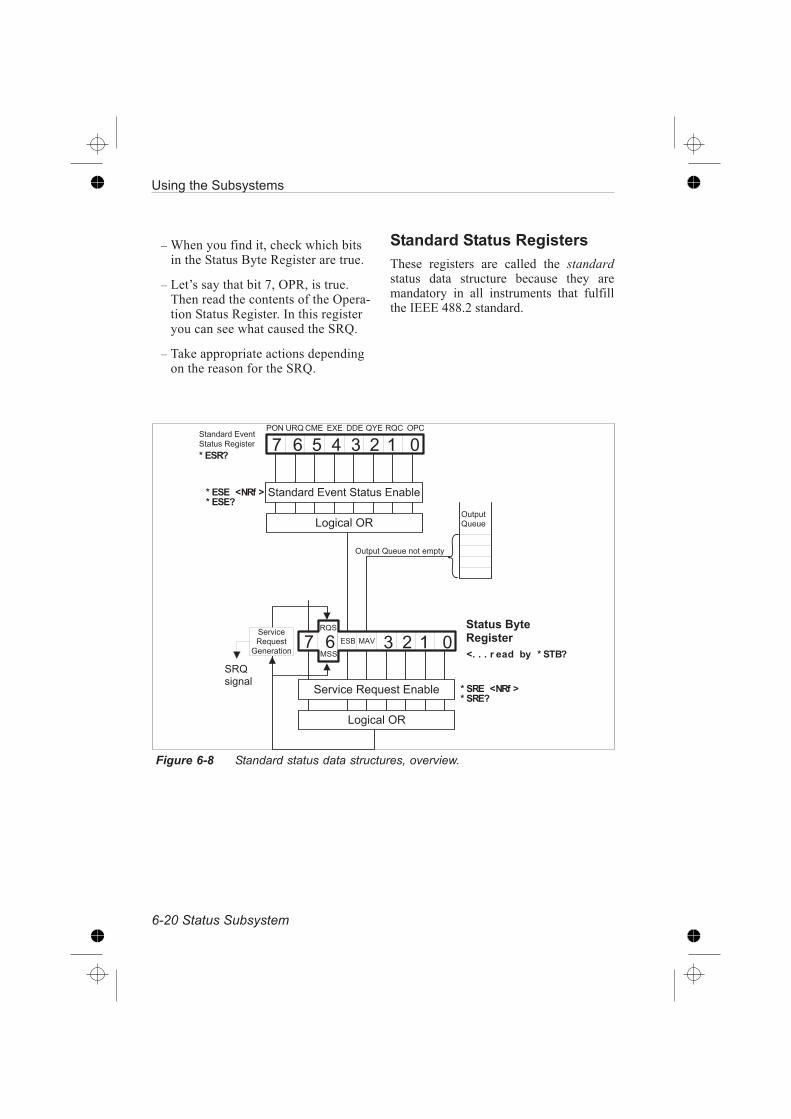
– When you find it, check which bitsin the Status Byte Register are true.
– Let’s say that bit 7, OPR, is true.Then read the contents of the Opera-tion Status Register. In this registeryou can see what caused the SRQ.
– Take appropriate actions dependingon the reason for the SRQ.
Standard Status Registers
These registers are called the standardstatus data structure because they aremandatory in all instruments that fulfillthe IEEE 488.2 standard.
6-20 Status Subsystem
Using the Subsystems
< 9 $ < 9 ; < 2 < 2 . + 9 2 " $ 9 J
* * * ' ) + ,
2 ! C 3 : 2 2 G < 2 # 9 . 0 > B 2
+ = 3 : 0 B
& ) !
; # 3 = . 0 B
* ;
2 ! C 3 : 2 2 G < 2 # 9
2 . 2 ! 0 9 3 + .
9 0 . 1 0 ! 1 C 2 . 9 9 0 9 < # . 0 > B 2
+ = 3 : 0 B
*) (
< 9 $ < 9; < 2 < 2
)
+ - + ,
+ - + ,
9 0 . 1 0 ! 1 C 2 . 9
9 0 9 < # 2 = 3 # 9 2 !
+ ,
; ; ;
Figure 6-8 Standard status data structures, overview.

Standard Event Status Register
Bit 7 (weight 128) — Power-on (PON)
Shows that the counter’s power supply hasbeen turned off and on (since the last timethe controller read or cleared this register).
Bit 6 (weight 64)—User Request (URQ)
Shows that the user has pressed a key onthe front panel of CNT-8X (except LO-CAL/PRESET). The URQ bit will be setregardless of the remote local state of thecounter. The purpose of this signal is, forexample, to call for the attention of thecontroller by generating a service request.
Bit 5 (weight 32) — Command Error
(CME)
Shows that the instrument has detected acommand error. This means that it has re-ceived data that violates the syntax rulesfor program messages.
Bit 4 (weight 16) — Execution Error
(EXE)
Shows that the counter detected an errorwhile trying to execute a command. (See‘Error reporting’ on page 3-17.) Thecommand is syntactically correct, but thecounter cannot execute it, for examplebecause a parameter is out of range.
Bit 3 (weight 8) — Device-dependent
Error (DDE)
A device-dependent error is any deviceoperation that did not execute properlybecause of some internal condition, forinstance error queue overflow. This bitshows that the error was not a command,query or execution error.
Bit 2 (weight 4) — Query Error (QYE)
The output queue control detects query er-rors. For example the QYE bit shows theunterminated, interrupted, and deadlockconditions. For more details, see ‘Error re-porting’ on page 3-17.
Bit 1 (weight 2)—Request Control (RQC)
Shows the controller that the devicewants to become the active control-ler-in-charge. Not used in the CNT-8X.
Bit 0 (weight 1) — Operation Complete
(OPC)
The counter only sets this bit TRUE in re-sponse to the operation complete com-mand (*OPC). It shows that the counterhas completed all previously started ac-tions.
Summary, Standard Event
Status Reporting
*ESE <bit mask>
Enable reporting of Standard Event Sta-tus in the status byte.
*SRE 32
Enable SRQ when the Standard Eventstructure has something to report.
Using the Subsystems
Status Subsystem 6-21
Figure 6-9 Bits in the standard event
status register

ESR?
Reading and clearing the event register ofthe Standard Event structure.
SCPI-defined StatusRegisters
CNT-8X has two 16-bit SCPI-definedstatus structures: The operation status andthe questionable data structure. Thesegroup is 16-bits wide while the statusbyte and the standard status groups are8-bits wide.
6-22 Status Subsystem
Using the Subsystems
+ = 3 : 0 B
. 0 > B 2 2 = 3 # 9 2 !
C 2 . 9 2 = 3 # 9 2 !
!
2 ! C 3 : 2 2 G < 2 # 9 . 0 > B 2
+ = 3 : 0 B
9 0 9 < # J 9 2 2 = 3 # 9 2 !
+ = 3 : 0 B + = 3 : 0 B
+ . 1 3 9 3 + . 2 = 3 # 9 2 !
. 0 > B 2 2 = 3 # 9 2 !
C 2 . 9 2 = 3 # 9 2 !
+ = 3 : 0 B
+ . 1 3 9 3 + . 2 = 3 # 9 2 !
. 0 > B 2 2 = 3 # 9 2 !
C 2 . 9 2 = 3 # 9 2 !
" !
C 2 . 9 2 = 3 # 9 2 !
. 0 > B 2 2 = 3 # 9 2 !
! # $ % & !
" & ' ! "&&
$&%&"&&
(*)
Figure 6-10 Status structure 7, Operation Status Group, and Status structure 3,
Questionable Data Group are SCPI defined.

Operation Status Group
This group reports the status of theCNT-8X measurement cycle.
Bit 8 (weight 256) — Measurement
Stopped (MSP)
This bit shows that the counter is not mea-suring. It is set when the measurement, orsequence of measurements, stops.
Bit 6 (weight 64) — Wait for Bus Arm-
ing (WFA)
This bit shows that the counter is waitingfor bus arming in the arm state of the trig-ger model.
Bit 5 (weight 32) — Waiting for Trigger
and/or External Arming (WFT)
This bit shows when the counter is readyto start a new measurement via the triggercontrol option (488.2), for the shortestpossible trigger delay. The counter is nowin the wait for the trigger state of the trig-ger model.
Bit 4 (weight 14) — Measurement
Started (MST)
This bit shows that the counter is measur-ing. It is set when the measurement or se-quence of measurements start.
Summary, Operation Status
Reporting
:STAT:OPER:ENAB
Enable reporting of Operation Status inthe status byte.
*SRE 128
Enable SRQ when operation status hassometing to report.
:STAT:OPER?
Reading and clearing the event register ofthe Operation Status Register structure
:STAT:OPER:COND?
Reading the condition register of the Op-eration Status Register structure.
Using the Subsystems
Status Subsystem 6-23
*, (
$ % & ( & % & . $ . $ , & . $ . / ,
* * * (
2 0 # < ! 2 " 2 . 9 # 9 + $ $ 2 1
0 3 9 3 . = F + ! 0 ! " 3 . =
0 3 9 3 . = F + ! 9 ! 3 = = 2 ! 3 . =
2 0 # < ! 2 " 2 . 9 # 9 0 ! 9 2 1
Figure 6-11 Bits in the Opeation Sta-
tus Register.

Questionable Data/SignalStatus Group
This group reports when the output datafrom the CNT-8X may not be trusted.
Bit 14 (weight 16384) — Unexpected
Parameter (UEP)
This bit shows that CNT-8X has receiveda parameter that it cannot execute, al-though the parameter is valid accordingto SCPI. This means that when this bit istrue, the instrument has not performed ameasurement exactly as requested.
Bit 10 (weight 1024) — Timeout for
Measurement (TIO)
The counter sets this bit true when itabandons the measurement because theinternal timeout has elapsed, or no signalhas been detected.See also :SYST:TOUT and:SYST:SDET.
Bit 8 (weight 256) Overflow (OFL)
The counter sets this bit true when it can-not complete the measurement due tooverflow.
Summary, Questionable
Data/Signal Status Reporting
:STAT:QUES:ENAB <bit mask>
Enable reporting of Questionabledata/signal status in the status byte.
*SRE 8
Enable SRQ when data/signal is ques-tionable.
:STAT:QUES?
Reading and clearing the event register ofthe Questionable data/signal Registerstructure.
:STAT:QUES:COND?
Reading the condition register of Ques-tionable data/signal Register structure.
6-24 Status Subsystem
Using the Subsystems
" & ' 0 ! & ( & %
, (
. " . $ , . " ,
*
. 2 I $ 2 : 9 2 1 $ 0 ! 0 " 2 9 2 !
3 " 2 + < 9 F + ! " 2 0 # < ! 2 " 2 . 9
C 2 ! F B + 4
* , ( (
Figure 6-12 Bits in Questionable data
register.

Device-defined Status StructureCNT-8X has one device-defined statusstructure called the Device Register 0. Itsummarizes this structure in bit 0 of the
status byte. Its purpose is to report whenthe measuring result has exceeded pre-programmed limits.
Using the Subsystems
Status Subsystem 6-25
Logical OR
Enable Register
Event Register
Standard Event Register
Service Request Enable
Logical OR
Status Byte Register
Logical ORLogical OR
Condition Register
Enable Register
Event Register
Logical OR
Condition Register
Enable Register
Event Register
SRQ signal
Event Register
Enable Register
Device Register 0Operation Status Register
Questionable Data Register
Err
or
Qu
eu
e
Ou
tpu
tQ
ueu
e
01234567
Figure 6-13 Device-defined status data structures ( model ).

You set the limits with the followingcommands in the calculate subsystem.
:CALCulate:LIMit:UPPer and
:CALCulate:LIMit:LOWer
An example on how to use limit monitor-ing is available in Chapter 4, ‘ProgramExamples.’
Bit Definition
Bit 2 (weight 4) — Monitor of Low Limit
This bit is set when the low limit ispassed from above.
Bit 1 (weight 2) — Monitor of High Limit
This bit is set when the high limit ispassed from below.
Summary, Device-defined
Status Reporting
:STAT:DREG0:ENAB <bit mask>
Enable reporting of device-defined statusin the status byte.
*SRE 1
Enable SRQ when a limit is exceeded.
:STAT:DREG0?
Reading and clearing the event register ofDevice Register structure 0.
– If bit 1 is true, the high limit has been ex-
ceeded.
– If bit 2 is true, the low limit has been ex-
ceeded.
Power-on Status Clear
Power-on clears all event enable regis-ters and the service request enable regis-ter if the power-on status clear flag is setTRUE (see the common command*PSC.)
Preset the Status Reporting
Structure
You can preset the complete status struc-ture to a known state with a single com-mand, the STATus:PRESet command,which does the following:
– Disables all bits in the Standard Event
Register, the Operation Status Register, and
the Questionable Data Register
– Enables all bits in Device Register 0
– Leaves the Service Request Enable Regis-
ter unaffected.
6-26 Status Subsystem
Using the Subsystems
24
Monitoring of high limitMonitoring of low limit
Device Status Register0STAT:DREG0:COND?
STAT:DREG0?
2 1 015
Figure 6-14 Bits in the Device Status
Register number 0.
:STATus:DREGister0?
Reads out the contents
of the Device Status
event Register 0 and
clears the register.

Trigger/Arming Subsystem
The SCPI TRIGger subsystem enables syn-chronization of instrument actions withspecified internal or external events. Thefollowing list gives some examples.
Instrument Action
Some examples of events to synchronizewith are as follows:
– measurement
– bus trigger
– external signal level or pulse
– 10 occurrences of a pulse on the external
trigger input
– other instrument ready
– signal switching
– input signal present
– 1 second after input signal is present
– sourcing output signal
– switching system ready
The ARM-TRIG TriggerConfiguration
Figure 6-15 gives a typical trigger config-uration, the ARM-TRIG model. The con-figuration contains two event-detectionlayers: the ‘Wait for ARM’ and ‘Wait forTRIG’ states.
Using the Subsystems
Trigger/Arming Subsystem 6-27
Initiated
Idle
Trigger system initiated
Still initiated
ARM conditions satisfied
TRIGger conditions satisfied
Wait for ARM
Wait for TRIG
Instrument Actions
No longer initiated
Completed No. of ARM loops
Completed No. of TRIGger loops
Instrument Actions complete
Default state after power-on or reset
Arm Layer
Trigger Layer
Trigger system initiated
ABORt
*RST
pon
Figure 6-15 Generalized ARM-TRIG
model.

This trigger configuration is sufficient formost instruments. More complex instru-ments, such as the CNT-8X, have moreARM layers.
The ‘Wait for TRIG’ event-detectionlayer is always the last to be crossed be-fore instrument actions can take place.
Structure of the IDLE andINITIATED States
When you turn on the power or send*RST or :ABORT to the instrument, itsets the trigger system in the IDLE state;see .
The trigger system will exit from theIDLE state when the instrument receivesan INITiate:IMMediate. The in-strument will pass directly through theINITIATED state downward to the nextevent-detection layers (if the instrumentcontains any more layers).
The trigger system will return to the INI-TIATED state when all events requiredby the detection layers have occurred andthe instrument has made the intendedmeasurement. When you program thetrigger system to INITiate:CONTin-uous ON, the instrument will directlyexit the INITIATED state moving down-ward and will repeat the whole flow de-scribed above. WhenINITiate:CONTinuous is OFF,the trigger system will return to the IDLEstate.
Structure of an Event-detection
Layer
The general structure of allevent-detection layers is identical and isroughly depicted by the flow diagram in
In each layer there are several program-mable conditions, which must be satisfiedto pass by the layer in a downward direc-tion:
Forward Traversing an
Event-detection Layer
After initiating the loop counters, the in-strument waits for the event to be de-tected. You can select the event to bedetected by using the <layer>:SOURcecommand. For example::ARM:LAYer2:SOURce BUS
You can specify a more precise character-istic of the event to occur. For example::ARM:LAYer:DELay 0.1
You may program a certain delay be-tween the occurrence of the event and en-tering into the next layer (or starting thedevice actions when in the TRIGger
6-28 Trigger/Arming Subsystem
Using the Subsystems
@ ? A + ! ? K
@ ? A + ! ? K
+
2 #
L 9
$ + .
+
2 #
Figure 6-16 Flow diagram of IDLE
and INITIADED layers.

layer). This delay can be programmed byusing the <layer>:DELay command.
Backward Traversing an
Event-detection Layer
The number of times a layer event has toinitiate a device action can be pro-grammed by using the <layer>:COUNtcommand. For example::TRIGger:COUNt 3 causes the in-strument to measure three times, eachmeasurement being triggered by the spec-ified events.
Triggering
*TRG Trigger Command
The trigger command has the same func-tion as the Group Execute Trigger com-mand GET, defined by IEEE 488.1.
When to use *TRG and GET
The *TRG and the GET commands havethe same effect on the instrument. If theCounter is in idle, i.e., not parsing or exe-cuting any commands, GET will execute
much (≈ 20 µs) faster than *TRG
(≈ 4 ms) since the instrument must al-ways parse *TRG.
Using the Subsystems
Trigger/Arming Subsystem 6-29

Using the Subsystems
6-30 Trigger/Arming Subsystem
C 2 . 9 1 2 9 2 : 9 3 + .
7 B 0 J 2 ! 8 ? : 2
2 1 3 0 9 2
&
)
0 J 2 ! B + + $ : + < . 9 2 ! &
C 2 . 9 1 2 9 2 : 9 3 + .
? 27 B 0 J 2 ! 8 ? : 2
0 3 9 ? 0 J
. : ! 2 " 2 . 9 B 0 J 2 ! B + + $
: + < . 9 2 ! > J
2 ! . 0 B (
2 1 3 0 9 2
+
2 #
&
1
7 B 0 J 2 ! 8 ? 0 J
)
7 B 0 J 2 ! 8 ? 9
0 J 2 ! B + + $ : + < . 9 2 ! &
C 2 . 9 1 2 9 2 : 9 3 + .
7 B 0 J 2 ! 8 ? : 2
+ " $ B 2 9 2 1 + % + F B 0 J 2 ! B + + $ : + < . 9 # K
. : ! 2 " 2 . 9 B 0 J 2 ! B + + $
: + < . 9 2 ! > J
2 1 3 0 9 2
+
2 #
&
)
7 B 0 J 2 ! 8 ? 9
! " 3 . = 9 0 ! 9 0 J 2 ! M > < # 9 ! 3 = N
! " 3 . = 9 0 ! 9 0 J 2 ! M I 9 2 ! . 0 B : + . 9 ! + B N
! 3 = = 2 ! 9 0 ! 9 0 J 2 ! M < " > 2 ! + F " 2 0 # < ! 2 " 2 . 9 # + . 2 0 : E 0 ! " N
+ " $ B 2 9 2 1 + % + F B 0 J 2 ! B + + $ : + < . 9 # K
7 B 0 J 2 ! 8 ? 2 1 3 0 9 2

Chapter 7
How to Measure Fast

Introduction
The CNT-8X counters can complete ameasurement cycle in many differentways, each with its own advantage. Thismeans that your first step is to select a ba-sic “measurement scenario” based on therequirements of the measurement. Thischapter contains some measurement sce-narios that you can choose from.
These counters can measure with impres-sive speed if you program them correctly.You will find guidelines for speed im-provements in each of the described mea-surement scenarios.
Controller Synchronization
The start of measurements can either beindividually or block synchronized by thecontroller. The instrument-to-controllersynchronization deals with how to start ameasurement or sequence of measure-ments and to read data in the most effi-cient way. You can also synchronize themeasurement with the measuring objectmore accurately by using external control(arming), but this is not described here.
Measurement CycleSynchronization
It is a good practice to check that themeasurement proceeds as planned whenthe controller has started a measurement,or block of measurements.
Start
If the input signal fails, or there is noarming etc., the measurement cycle willnot start.
Timeout
Turn on timeout and set the time longerthan the expected measurement cycle.Then wait for the timeout period, andtake actions if you got timeout.
If the measurement time is long, you mayhave to wait many seconds or even min-utes until timeout, just to learn that themeasurement never started.
Measurement started
Before starting a measurement, set up thestatus reporting system so that you get aService Request on Measure-ment-in-progress, bit 4 in the OperationStatus Event Register. Check this with se-rial poll after a reasonable time when themeasurement ought to be started, lets sayafter 100ms (time dependent on input sig-nal frequency). If the bit is true, continue.If false, abort the measurement and checkthe signals, alert the operator etc.
Stop
You must also know when the measure-ment is completed in order to read out theresults. Should you read results or sendother commands before the measurementis completed, the measurement will be in-terrupted.
You can of course let the controller waituntil you are absolutely certain that theresult is ready, before you fetch it. But itis better to use *OPC to get an OperationComplete status message, or *OPC? toget an ASCii “1” in the output queue,when the measurement is ready.
*OPC and *OPC? are common com-mands described on page 9-124 and9-125.
7-2 Introduction
How to Measure Fast

*OPC reports when operation is com-plete, via the Status Subsystem describedon page 6-14.
Rough TriggerSubsystemDescription
The trigger subsystem is the functionalpart of the CNT-8X that controls the startand stop of measurements. This is thefunction that the controller interacts withwhen it controls the measurement se-quence.
A simplified model of the CNT-8X’s trig-ger subsystem is a state-machine withfour different states. These states are asfollows:
IDLE State
– The counter waits for new commands. It is
not measuring
WAIT_FOR_BUS_ARM State
– The counter is ready to receive a bus arm-
ing signal, GET or TRG.
WAIT_ FOR_MEASUREMENT_TO_
START State
– The counter waits for the input signal trig-
gering to start the measurement or block of
measurements. If the counter uses arming,
it is waiting for the specified arming event.
MEASUREMENT State
– The counter measures. It monitors the
hardware and controls the measurement
time. If block measurement mode is used,
(ARM:COUN or TRIG:COUN2) the
counter stays in this state until all measure-
ments inside the block has been made.
Different actions cause the trigger sub-system to change between the differentstates. The transitions are shown in . Thestatus is reflected in status byte:STATus:OPERation:CONDition.
How to Measure Fast
Rough Trigger Subsystem Description 7-3
9 0 9 2 ? $ 2 ! 0 9 3 + . + . 1 3 9 3 + .! 2 = 3 # 9 2 ! # 9 0 9 < # ? 2 3 4
9 0 9 2 ?5 6 $ 7
$ 2 ! 0 9 3 + . + . 1 3 9 3 + . ! 2 = 3 # 9 2 !# 9 0 9 < # ? 8 2 #
9 0 9 2 ?5 6 $ 9 7 0
( $ 2 ! 0 9 3 + . + . 1 3 9 3 + . ! 2 = 3 # 9 2 !
# 9 0 9 < # ? 2 : :
9 0 9 2 ?7
$ 2 ! 0 9 3 + . + . 1 3 9 3 + .! 2 = 3 # 9 2 ! # 9 0 9 < # ? ; 4
+ !
! 0 B B " 2 0 # < ! 2 " 2 . 9 #: + " $ B 2 9 2 1
< # 9 ! 3 = ! 2 : 2 3 C 2 1 + ! M 3 " " 2 1 3 0 9 2 N
B B 0 . 1 B + + $ # : + " $ B 2 9 2 1
M ! " 3 . = ! 2 : 2 3 C 2 1 + !0 ! " + F F M 3 " " 2 1 3 0 9 2 N N
0 . 1 3 . $ < 9 9 ! 3 =
3 . = B 2 " 2 0 # < ! 2 " 2 . 9! 2 0 1 J
Figure 7-1 Trigger subsystem states.

Some BasicCommands
Here follows a description of some basicCNT-8X commands that control the mea-surement sequence.
CONFigureThe CONFigure command sets up thecounter to do the measurement specifiedby the parameters of the command. Thecommand gives a limited number of pa-rameter options such as:
– Measurement function
– Measurement channel
– Number of measurements and sometimes
also the following:
– Measuring time
– Trigger level
The counter sets up the rest of its func-tions in the best way for the requestedmeasurement. This means that any instru-ment setting may be changed by thiscommand.
Examples:
– Set up to measure frequency:
CONF:FREQ
– Set up to do 100 frequency measurements:
CONF:ARRay:FREQ(100)
– Set up to do 100 frequency measurements
on the A-channel:
CONF:ARRay:FREQ(100),(@1)
– Set up to do 100 frequency measurements
on the A-channel. Expected frequency 10
MHz that should be measured with a reso-
lution of 1 Hz.
CONF:ARRay:FREQ
(100),10e6,1,(@1)
INITiateThe INITiate command will normallystart a measurement or measurement se-quence and store the result internally inthe CNT-8X. However the actual actionis to change the state of the trigger sub-system from “idle” to“wait_for_bus_arming”. The result ofchanging the state of the trigger subsys-tem depends on the programming of thissubsystem. For example it could be pro-grammed to do the following:
– Make 1000 measurements.
– Wait for a GET/*TRG and then start a
measurement.
– Wait for a GET and then make 534 mea-
surements.
– Wait for an arming pulse and make one
measurement.
– Wait for an arming pulse and make 234
measurements.
INITiate :CONTinuous
This command sets the counter in a modewhere it continues with a new measure-ment immediately after it has finished theprevious one. This is done by not return-ing the trigger subsystem to the “idle”state.
ABORt
This command stops the current measure-ment (if any), and sets the trigger subsys-tem to the “idle” state. This means thatthe counter is only waiting for new com-mands.
FETCh?
The FETCh query retrieves measurementdata. It could either be a single value(SCALar) or a series of values (ARRay).
7-4 Some Basic Commands
How to Measure Fast

Examples:
– Get one measurement: FETCh?
– Get 100 measurements:
FETCh:ARRay?100
The number of measurements isdefined by the setting of the ARMand TRIG counters. The ARMcounter can be set directly by the:CONF and :MEAS commands.The :FETCh:ARRay? query pa-rameter only decides how manymeasurement results to read out.
READ?
This command simply means to start ameasurement or measurement sequenceand read data.
This query is identical to:ABORt;INITiate;FETCh?
This means that the counter starts a mea-surement ( single or array) after it hasaborted any previous measurements. Italso returns the result.
Examples:
– Start one measurement and fetch result:
READ?
– Start measurements and fetch 100 results:
READ:ARRay?100
MEASure?
This query is identical to:CONFigure;READ?
This means that the command sets up thecounter and starts a measurement/mea-surement sequence.
Examples:
– Make a frequency measurement:
MEAS:FREQ?
– Make 100 frequency measurements:
MEAS:ARRay:FREQ?(100)
– Make 100 frequency measurements on the
A-channel:
MEAS:ARRay:FREQ? (100),(@1)
– Make 100 frequency measurements on the
A-channel. The expected frequency to be
measured is 10MHz with a resolution of 1
Hz.
MEAS:ARRay:FREQ?
(100),10e6,1,(@1)
MEAS:MEM1?, MEAS:MEM? 10
Memory Recall, Measure and Fetch Result
This command is only for PM6681. Useit when you want to measure several pa-rameters fast, i.e., switch quickly be-tween measurement functions.
MEAS:MEM1? recalls the contents ofmemory 1 and reads out the result,MEAS:MEM2? recalls the contents ofmemory two and reads out the result etc.
The equivalent command sequence is*RCL1;READ?
The allowed range for <N> is 1 to 9. Usethe somewhat slower MEAS:MEM-ory?N command if you must use mem-ories 10 to 19.
Command
TIMING
Data Format
ASCII REAL
MEAS:MEM1? 7.9 ms 6.7 ms
MEAS:MEM?1 9.1 ms 8.0 ms
*RCL 1;READ? 10.1 ms 8.9 ms
How to Measure Fast
Some Basic Commands 7-5

Basic MeasurementMethod
A basic measurement method for a sys-tem composed of signal sources, measur-ing object, and measuring devices will bea simple step-by-step procedure. Thisprocedure goes as follows:
Step 1: Set up signal sources
Step 2: Set up measurement devices
Step 3: Trigger measurement devices
Step 4: Read data
Step 5: Evaluate data
The above procedure may be repeated asmany times as required.
The methods described here deal withhow you should do steps 3 and 4 in thebest and most efficient way with theCNT-8X.
Individually SynchronizedMeasurements
This is a method that you should usewhen you need to start each measurementexternally from the controller. The mostprobable reason that you should use indi-vidually synchronized measurements isthat you need to evaluate data in real timeand make decisions depending on the ac-quired data. An example of this could beto tune an oscillator by measuring theoutput frequency and adjust the oscillatordepending on the measured frequency.
Of the many available ways to do thiswith the CNT-8X, three should be men-tioned: READ?, INIT:CONT and GETand MEASure?
READ?
The READ? query provides a basicmechanism for this. It ensures that themeasurement is started after the counterreceives the command. It will also sendback the result. The READ? query shouldbe preceded by setting up the counter byusing either CONFigure or individualprogramming commands. This commandshould be used if no special speed re-quirements exists.
INIT:CONT and GET
In this method the trigger function is con-tinuously initiated by the command INI-
Tiate:CONTinuous1. This gives youthe minimal firmware overhead if youdon’t change settings in the counter. Setup the counter either by using CONFig-ure, or by using individual programmingcommands before starting the measuringsequence. Setting up includes switchingon the “wait for bus trigger” functionwith the following command:
ARM:START:LAY2:SOURceBUS.
As default, the counter starts a measure-ment and sends the result to the controllerwhen receiving a GET or a *TRG com-mand. This method is the fastest way tomake individually synchronized measure-ments.
MEASure?
The MEASure? query sets up the coun-ter, ensures that the measurement isstarted after the command is received,and also sends the result to the controller.This command has the highest possibledegree of compatibility to other instru-ments; however the command reprogramsthe counter, and often you need to set up
7-6 Basic Measurement Method
How to Measure Fast
the counter by yourself. This is primarilywhy we recommend the READ? query.
Block SynchronizedMeasurements
In the block synchronized mode, the con-troller only starts a sequence of measure-ments. The counter then measures,without any controller intervention, at thehighest possible speed. It “dumps” the re-sults into internal memory and reads themout for evaluation later. This methodgives the highest possible data capturespeed.
READ:ARRay?
This is the basic method for starting up ameasurement sequence and reading thedata. Set up the counter using CONFigureor individual programming commandsbefore sending the READ:ARRay?query. This method will make the mea-surements with a high measurement rate.The speed depends on a number of indi-vidual measurement parameters; see also“General speed improvements” below.The counter stores the data in its internalmemory and when it has captured alldata, it transfers the resulting array to thecontroller.
INIT + GET + FETCH:ARRay?
The READ:ARRay? method has onedrawback, it includes some unwantedfirmware overhead between when thecounter receives the command and itstarts the first measurement. This can besolved by setting up the counter to waitfor a GET before it starts the measure-ment sequence. The default actions forGET include sending a single result ( thefirst value) when the counter has com-pleted the sequence. This makes it possi-
ble to let the controller wait for the Mes-sage AVailable status bit to find out whenthe data capture is ready. You can readthe complete array by using theFETCH:ARRay? command. So if, forexample, the array size is 4, GET givesthe first result in the array andFETC:ARR?3 fetches result two, three,and four.
MEAS:ARRay?
The MEASure:ARRay? query ensuresthat the measurement sequence is startedafter the command is received. It will alsosend back the results. It also includes set-ting up the counter. This is the commandthat has the highest possible degree ofcompatibility with other instruments;however, this command reprograms thecounter and often you need to programthe counter yourself. This is why we rec-ommend using the READ:ARRay?query.
General SpeedImprovements
The CNT-8X has many options to im-prove measurement speed. Here you willget a list of actions that you can use toimprove the measurement speed. Most ofthese commands decrease the averagedead time. The dead time is the time be-tween measurements, that is, from stop tothe next start. These actions are all gen-eral, that is, they affect the rate of mea-surements for all measurement methodsgiven above; however, they are especiallyvaluable for the block synchronized mea-surements. In this mode, the dead time
can be as low as 120µs ( PM6681 ).
How to Measure Fast
General Speed Improvements 7-7

AUTO
One of the most timesaving commandsyou can use with the CNT-8X is:INPut:LEVel:AUTOOFF. This willsave the time it takes to determine thetrigger levels. (About 50ms/measurementin PM6680B and PM6685, and 85ms inPM6681.)
Display Control
The display can be switched off with thecommandDISPlay:ENABleOFF. When youswitch off the display, the counter losesthe measurement data resolution informa-tion. This means that the counter alwayssends all digits independently of whetheror not they are significant. This commandreduces the dead time by about 7ms.
GPIB Data Format
You can select the format of the resultsent on the GPIB using the FORMatcommand. Two options exist: ASCii andREAL. The REAL format saves a lot oftime both in the instrument and the con-troller for converting data. However,when the counter uses the REAL format,you lose the measurement data resolutioninformation. It sends the REAL format asa block data element. This means that itsends data as:#18< 8 bytes real>.
The <8 bytes real> is a double precisionbinary floating-point code according toIEEE 488.2 / IEEE 754.
Time MeasurementResolution
The basic time measurement resolutioncan be selected by using the commandSENSe:ACQ:RES«HIGH|LOW».When you set the resolution to low it willbe 100ns for PM6680B and PM6685, and80ns for PM6681. Instead of the high res-olution, which is 0.25ns for PM6680Band PM6685, and 0.05ns for PM6681.
If the counter does real-time calculationsand you switch to low resolution, themeasurement dead time decreases about0.6 to 0.9ms. If the counter does not doreal-time calculations, then it saves onlyabout 0.05ms per measurement cycle. Ifthe counter does real time calculationswith the display switched on, then youcan save up to 2ms by selecting the lowerresolution.
Automatic InterpolatorCalibration (PM6680B/85)
The time interpolation technique achievesthe high time resolution. The counter au-tomatically calibrates these interpolatorsonce per measurement cycle. You cancontrol this automatic calibration by us-ing the command:CAL:INT:AUTO «ON|OFF|ONCE».When you switch calibration off, themeasurement cycle time decreases.
Disabling this calibration makes thecounter more sensitive to temperaturechanges. The measurement values maydrift away, which results in a larger inac-curacy. However, when the instrumenthas been switched on for more than 20minutes and the ambient temperature is
stable within ± 5°C, this is no problem.You can also easily recalibrate the
7-8 General Speed Improvements
How to Measure Fast

interpolators by using theCAL:INT:AUTO ONCE command.
Block Measurements
When dumping measurement results intothe internal memory, it is important toprogram the arming and triggering coun-ters in the best way. For maximum mea-surement rate use the block armed mode.To do this set::ARM:STARt:LAYer:COUNt1andTRIG:COUNt <N>where <N> is the number of measure-ments in a block.
Real Time Calculation
Normally the counter calculates the re-sults in “real time.” This means that foreach measurement, the counter immedi-ately calculates the result based on theraw data information in various countingregisters. It needs to do this in order todisplay the result, make mathematicalcalculations, limit testing and statisticalcalculations. It is possible to defer thecalculations until the controller requeststhese values. The counter intermediatelystores the measurement data in a packedformat. This is done with the command::SENSe:INTernal:FORMat PACKed.
This is the most important com-mand when you want to improvethe measurement rate for blocksynchronized measurements.
Note: If you want a very high speed
you must set :AVER:STATEOFF and
:ACQ:APER MIN.
40000 measure-ments/second
(Only PM6681)
PM6681 can make measure every periodof a signal with up to 40 000 Hz. This iscalled “Back-to-Back” period measure-ments and in only available via GPIB.The high speed is obtained when thePM6681 measures low-resolution mea-surements directly to its internal memory.That memory can store 6143 measure-ment results. When full, the measurementmust be stopped, and the results fetchedby the controller. )
Note also that some functions are dis-abled to obtain high measurement speed:You cannot use external arm/trig orhold-off. Statistics is also disabled.
Example: 1000 back-to-back periods
:SENS:FUNC"PER1"Select period as measurement function
:INP:COUPDC Select DC coupling
:INP:LEV:AUTOOFF Turn off Auto Trigger
:INP:LEV1 Set fixed trigger level
:SENS:ACQ:RESLOW Select low resolu-
tion/high speed measurements
:SENS:INT:FORMPACK Suspends the re-
sult calculation until the capture is
ready
:TRIG:COUN1000;:ARM:COUN1 Set up
PM6681 for 1000 measurements
:INIT Start a capture
:FETC:ARR?1000 Fetch the 1000 results
from the internal PM6681 memory
How to Measure Fast
40000 measure- ments/second 7-9

Supervising aProcess
One typical use of a counter in the indus-try is to measure a parameter and alert theadjusting machinery when the parametergets close to the correct value. The ma-chinery now slows down for an accuratefinal adjustment of the parameter, andstops the adjustment procedure when thevalue is correct.
An example of such a procedure is whena laser adjusts the value of a resistor thatis connected to an oscillator. You mea-sure the frequency of the oscillator andthe laser cuts the resistor until the oscilla-tor oscillates at the correct frequency.
Obvious Method
The most obvious way to do this may beas follows:
– Let the counter measure the frequency.
– Send the result to the controller.
– Let the controller, that controls both the la-
ser cutter and the counter, decide when to
slow down the cutting procedure, and
eventually switch the laser off when the
correct frequency is obtained.
This method works fine for slow pro-cesses but the bus transfer rate of thecounter limits the measuring speed toaround 125 measurements/s forPM6680B and PM6685, and 250 mea-surements/s for PM6681. If all speed in-creasing actions are taken, and onlyaround 10 measurements/s if no speed in-creasing actions taken.
Optimal Method
An experienced CNT-8X programmerknows that he can increase the processspeed to over 300 measurements/second,by letting the counter do more and thecontroller less of the job:
– Set up the counter to measure continuously
with low resolution, without displaying or
reading out any results.
– Set up limit monitoring so that the counter
issues a service request when the frequency
reaches the limit where the laser should
slow down.
– Proceed with one of the following:
– Alternative 1: The program slows down the
laser and recalls new narrower limits from
the internal counter memory and selects
higher resolution.
– Alternative 2: The program slows down the
laser and reprograms the counter to make
high resolution measurements and reports
each measurement result to the controller.
– The controller stops the process when the
desired result is obtained.
See also the limit monitoring program-ming example in Chapter 4.
7-10 Supervising a Process
How to Measure Fast

Speed Summary
The following table summarizes the timethat can be gained when fine tuning themeasurement process.
The normal dead time between frequencymeasurements is approximately as fol-lows:
48.8 ms for the PM6680B.85 ms for the PM6681.75 ms for the PM6685.
If you should read out the measuring re-sult to the controller add read out time toeach result. (Consult your controller man-ual.)
Turning the real-time calculations on/off will not affect the dead time because thecalculations are still done inside the measurement loop during the output of data.
* It takes longer time for PM6681 to determine trigger levels than for PM6680B,why? The reason is that PM6681 must find the correct level from 16 times as manytriggerlevel setting steps than thePM6680B/85 (1.25 mV steps versus 20mV steps).
How to Measure Fast
Speed Summary 7-11
Individually Synchronized Measurements
Speed Improvement
Actions
None,norm
alR
EA
D?
AU
TO
trig
ger
OF
F
INT:
CO
NT
and
GE
T
Dis
pla
yO
FF
CA
L:IN
T:A
UT
OO
FF
100ns
reso
lutio
n
Dead Time Between Measurements Including
Transfer to Controller
ASCII Data Format Real Data Format
PM6680B PM6681 PM6685 PM6680B PM6681 PM6685
Approx.50 ms
Approx.85 ms*
Approx.75 ms
Approx.45 ms
Approx.85 ms*
Approx.75 ms
19 ms 10 ms 23 ms 15 ms 9 ms 20 ms
12 ms 9 ms 20 ms 9 ms 8 ms 17 ms
12 ms 5.5 ms 12 ms 9 ms 4.2 ms 9 ms
12 ms 5.5 ms 12 ms 8 ms 4.2 ms 8 ms

7-12 Speed Summary
How to Measure Fast
(
*
)
,
-
20#<! 2"2.9 # #2:+.1
, ) ( 5
2 0 # < ! 2 " 2 . 9 3 " 2
5 . +
5 0 B B
2 0 B 1 0 9 0 5 . +
2 0 B 1 0 9 0 5 0 B B
% & ) ) * &
* * ,
(
*
,
(
*
,
(
20#<! 2"2.9 # #2:+.1
, , * 5 ( )
(
5 5
5
2 0 # < ! 2 " 2 . 9 3 " 2
5 . +
5 0 B B
2 0 B 1 0 9 0 5 . +
2 0 B 1 0 9 0 5 0 B B
% & ) ) * &
* * ,
(
*
)
,
-
20#<! 2"2.9 # #2:+.1
, 5 ) ( 5
2 0 # < ! 2 " 2 . 9 3 " 2
5 . +
5 0 B B
2 0 B 1 0 9 0 5 . +
2 0 B 1 0 9 0 5 0 B B
% & ) ) * &
* * ,

How to Measure Fast
Speed Summary 7-13
Block Synchronized Measurements
(:ARM:STARt:LAYer:COUNt 1 and TRIG:COUNt <N>)
Speed Improvement Actions
Dead Time Between Measurements
CA
L:IN
T:A
UT
OO
FF
Dis
pla
yO
FF
Realti
me
calc
ula
tions
OF
F([
SE
NS
]:IN
T:F
OR
MP
AC
K)
Low
reso
lutio
n([
SE
NS
]:A
CQ
:RE
SLO
W)
PM6680B PM6681 PM6685
9 ms 4.5 ms 9 ms
2 ms 1.3 ms 2.5 ms
0.5 ms 0.12 ms 0.6 ms
0.5 ms 0.025 ms* 0.6 ms
1: The GPIB format command will not affect the dead time for the block synchro-nized mode because the counter captures all data before transferring it to the con-troller.
2: Switching the real time calculations on/off In the block synchronized mode willsignificantly decrease the dead time; however, the time for calculations ( 2 ms forPM6680B/85 and 1 ms for PM6681) is added to the transfer time.
* In PM6681, low resolution is used for Back-to-Back period measurements.The measuring time has no effect in this mode. Only the Timestamps are used.

Calculating the MeasurementSpeed
When opimizing your program for speed,add the measuring time you use to thedead time, and subtract the time gain forthe timesaving commands you intend touse; all times should be expressed in sec-onds:
1
Meas time DeadTime TimeGain.
= number of measurements / second.
Where:
Meas.time is the measurement time
you use.
Deadtime is the deadtime between
measurements after preset. see page
7-11.
Timegain is the timegain in the table
on page 7-15.
7-14 Speed Summary
How to Measure Fast
)
)
20#<! 2"2.9 # #2:+.1
, ) ( 5
2 0 # < ! 2 " 2 . 9 3 " 2
B + : H 1 0 9 0 5 0 B B
B + : H 1 0 9 0 5 . +
% < ) * &
* * ,
(
*
)
,
20#<! 2"2.9 # #2:+.1
M E+<#0.1#N
, , * 5 ( )
(
5 5
5
2 0 # < ! 2 " 2 . 9 3 " 2
B + : H 1 0 9 0 5 0 B B
B + : H 1 0 9 0 5 . +
% < ) * &
* * ,
)
)
20#<! 2"2.9 # #2:+.1
, 5 ) ( 5
2 0 # < ! 2 " 2 . 9 3 " 2
B + : H 1 0 9 0 5 0 B B
B + : H 1 0 9 0 5 . +
% < ) * &
* * ,

How to Measure Fast
Speed Summary 7-15
Timesaving Com-
mands
Time Gain in ms Sacrifice
PM6680B PM6681 PM6685
Freq Freq Freq
FREQ:RANG:LOWMAX (23) (23) 10kHz lower freq. limit for AUTO. This
Timesaving is only possible when
AUTO is on.
(55) 50kHz lower freq. limit for AUTO. This
Timesaving is only possible when
AUTO is on.
INP:LEV:AUTOOFF 40 70 52 You have to set trigger levels manually.
DISP:ENABOFF 5.4 3.5 7.7 Only the controller can read the result.
CAL:INT:AUTOOFF 0.22 N.A. 0.22 You must instruct the counter to cali-
brate the interpolators once in a while
to maintain accuracy.
SENS:ACQ:RESLOW 0.81 0 / 0.1 0.81 Works up to about 40kHz. The resolu-
tion of each measurement drops to
100ns for PM6680B/85 and 80ns for
PM6681
(PM6681 Only: Gives Back-to-back
measurements in period, i.e. every pe-
riod in a block is measured)
TRIG:COUNT2100 0.69 N.A. 0.69 No sacrifice, the program loop in the
counter gets shorter, saving time.TRIG:COUNT6143 N.A. 4.2 N.A.
INT:FORMPACK 1.15 1.2 1.15 You cannot use limit monitoring, math-
ematics etc. in the CALC subsystem,
nor the Display or the Output subsys-
tems.
TRIG:COUNT1000(or more)STAT:OPER:ENAB0ARM:STA:LAY2:SOUR IMMINP:LEV:AUTOOFF(All together)
N.A. 0.13 N.A. These commands (all together) will in-
crease measurement speed the last
step from about 4000 to over 8000
measurements/s
FORM:TINFOFF N.A. 0 N.A. No timestamping possible. This only
influences the read. Time stamps are
always registred internally.
All these time gain estimates are approximations valid for frequency A mea-surements and may be changed without notice. The time gain/loss depends onmeasuring function.

Single “Speed Switch”Command for PM6680B/85
Since many parameters must be set to getthe highest measuring speed, it is simplerif you use the macro function:
Send the following lines to turn on mac-ros; define one macro called FASTFREQand one macro called SLOWFREQ.
SEND→ *EMC1
SEND→ *DMC‘FastFreq’,“:ACQ:APERMIN;:AVER:STATOFF;:INP:LEV:AUTO OFF;:DISP:ENABOFF;:CAL:INT:AUTOOFF;:SENS:ACQ:RESLOW”
SEND→ *DMC‘SlowFreq’,“:ACQ:APER200ms;:AVER:STATON;:INP:LEV:AUTOON;:DISP:ENABON;:CAL:INT:AUTOON;:SENS:ACQ:RESHIGH”
Now you just have to send FASTFREQ tothe counter to get high measurementspeed for frequency measurements, andSLOWFREQ to return to normal measur-ing speed.
Note that these macros includeall speed-increasing commandsfrom the table on the previouspage. Omit the ones you do notwant to use in your applicationand the ones that do not apply toyour counter.
Single “Speed Switch”Command for PM6681
Since many parameters must be set to getthe highest measuring speed, it is simplerif you use the macro function:
Send the following lines to turn on mac-ros; define one macro called FASTFREQand one macro called SLOWFREQ.
SEND→ *EMC1
SEND→ *DMC‘FastFreq’,“:ACQ:APERMIN;:AVER:STATOFF;:INP:LEV:AUTOOFF;:DISP:ENABOFF;:INT:FORMPACK;:SENS:ACQ:RESLOW;:FORM:TINFOFF;:TRIG:COUNT6143;:STAT:OPER:ENAB0;:ARM:STA:LAY2:SOURIMM"
SEND→ *DMC‘SlowFreq’,“:ACQ:APER200 ms;:AVER:STATON;:INP:LEV:AUTOON;:DISP:ENABON;:INT:FORMREAL;:SENS:ACQ:RESHIGH;:FORM:TINFON;:TRIG:COUNT1;:STAT:OPER:ENAB1;:ARM:STA:LAY2:SOURBUS"
Now you just have to send FASTFREQ tothe counter to get high measurementspeed for frequency measurements, andSLOWFREQ to return to normal measur-ing speed.
Note that these macros includeall speed-increasing commandsfrom the table on the previouspage. Omit the ones you do notwant to use in your application.
7-16 Speed Summary
How to Measure Fast

Chapter 8
Error Messages

Command Errors
Error
Number
Error Description Description/Explanation/Examples
0 No error
–100 Command error This is the generic syntax error for devices that can-not detect more specific errors. This code indicatesonly that a Command Error defined in IEEE-488.2,11.5.1.1.4 has occurred.
–101 Invalid character A syntactic element contains a character which is in-valid for that type; for example, a header containingan ampersand, SETUP&. This error might be usedin place of errors –114, –121, –141, and perhapssome others.
–102 Syntax error An unrecognized command or data type was encoun-tered; for example, a string was received when thecounter does not accept strings.
Syntax error; unrec-ognized data
–103 Invalid separator The parser was expecting a separator and encoun-tered an illegal character; for example, the semico-lon was omitted after a program message unit,
∗EMC1:CH1:VOLTS5.
–104 Data type error The parser recognized a data element different thanone allowed; for example, numeric or string datawas expected but block data was encountered.
Error Messages
8-2 Error Code 0 to -104
Read the Error/Event Queue
You read the error queue with the :SYS-Tem:ERRor? query.
Example:
SEND→ :SYSTem:ERRor?
READ← –100, “Command Error”
The query returns the error number fol-lowed by the error description.
If more than one error occurred, the querywill return the error that occurred first.When you read an error, you will also re-move it from the queue. You can read thenext error by repeating the query. Whenyou have read all errors, the queue is
empty, and the :SYSTem:ERRor?query will return:
0, “No error”
When errors occur and you do not readthese errors, the Error Queue may over-flow. Then the instrument will overwritethe last error in the queue with:
–350, “Queue overflow”
If more errors occur they will be dis-carded.
Read more about how to use er-ror reporting in the Introduction toSCPI chapter

Command Errors
Error
Number
Error Description Description/Explanation/Examples
–105 GET not allowed A Group Execute Trigger was received within a pro-gram message (see IEEE-488.2, 7.7).
–108 Parameter not al-lowed
More parameters were received than expected for
the header; for example, the ∗EMC common com-mand accepts only one parameter, so receiving
∗EMC0,,1 is not allowed.
–109 Missing parameter Fewer parameters were received than required for
the header; for example, the ∗EMC common com-
mand requires one parameter, so receiving ∗EMC isnot allowed.
–110 Command headererror
An error was detected in the header. This errormessage is used when the counter cannot detectthe more specific errors described for errors –111though –119.
–111 Header separatorerror
A character that is not a legal header separator wasencountered while parsing the header; for example,
no space followed the header, thus ∗GMC"MACRO"is an error.
–112 Program mnemonictoo long
The header contains more than 12 characters (seeIEEE-488.2, 7.6.1.4.1).
–113 Undefined header The header is syntactically correct, but it is unde-
fined for this specific counter; for example, ∗XYZ isnot defined for any device.
–114 Header suffix out ofrange
Indicates that a non-header character has been en-countered in what the parser expects is a header el-ement.
–120 Numeric data error This error, as well as errors –121 through –129, aregenerated when parsing a data element that ap-pears to be of a numeric type. This particular errormessage is used when the counter cannot detect amore specific error.
Numeric data error;overflow from con-version
Numeric data error;underflow from con-version
Numeric data error;not a number fromconversion
Error Messages
Error Code -105 to -120 8-3

Command Errors
Error
Number
Error Description Description/Explanation/Examples
–121 Invalid character innumber
An invalid character for the data type being parsedwas encountered; for example, an alpha in a deci-mal numeric or a “0" in octal data.
–123 Exponent too large The magnitude of the exponent was larger than32000 (see IEEE-488.2, 7.7.2.4.1).
–124 Too many digits The mantissa of a decimal numeric data element con-tained more than 255 digits excluding leading zeros(see IEEE-488.2, 7.7.2.4.1).
–128 Numeric data not al-lowed
A legal numeric data element was received, but thecounter does not accept it in this position for theheader.
–130 Suffix error This error as well as errors –131 through –139 isgenerated when parsing a suffix. This particular er-ror message is used when the counter cannot detecta more specific error.
–131 Invalid suffix The suffix does not follow the syntax described inIEEE-488.2, 7.7.3.2, or the suffix is inappropriate forthis counter.
–134 Suffix too long The suffix contained more than 12 characters (seeIEEE-488.2, 7.7.3.4).
–138 Suffix not allowed A suffix was encountered after a numeric elementthat does not allow suffixes.
–140 Character data error This error as well as errors 141 through –149 is gener-ated when parsing a character data element. This par-ticular error message is used when the counter cannotdetect a more specific error.
–141 Invalid characterdata
Either the character data element contains an invalidcharacter or the particular element received is notvalid for the header.
–144 Character data toolong
The character data element contains more than 12characters (see IEEE-488.2, 7.7.1.4).
–148 Character data notallowed
A legal character data element was encounteredwhere prohibited by the counter.
–150 String data error This error as well as errors –151 through –159 is gen-erated when parsing a string data element. This partic-ular error message is used when the counter cannotdetect a more specific error.
Error Messages
8-4 Error Code -121 to -150

Command Errors
Error
Number
Error Description Description/Explanation/Examples
–151 Invalid string data A string data element was expected, but was invalidfor some reason (see IEEE-488.2, 7.7.5.2); for ex-ample, an END message was received before theterminal quote character.
Invalid string data;unexpected end ofmessage
–158 String data not al-lowed
A string data element was encountered but was not al-lowed by PM6685 at this point in parsing.
–160 Block data error This error as well as errors –161 through –169 isgenerated when parsing a block data element. Thisparticular error message is used when PM6685 can-not detect a more specific error.
–161 Invalid block data A block data element was expected, but was invalidfor some reason (see IEEE-488.2, 7.7.6.2); for ex-ample, an END message was received before thelength was satisfied.
–168 Block data not al-lowed
A legal block data element was encountered butwas not allowed by the counter at this point in pars-ing.
–170 Expression data er-ror
This error as well as errors –171 through –179 isgenerated when parsing an expression data ele-ment. This particular error message is used if thecounter cannot detect a more specific error.
Expression data er-ror; floating-pointunderflow
The floating-point operations specified in the expres-sion caused a floating-point error.
Expression data er-ror; floating-pointoverflow
Expression data er-ror; not a number
Expression data er-ror; different numberof channels given
Two channel list specifications, giving primary andsecondary channels for 2-channel measurements,contained a different number of channels.
Error Messages
Error Code -151 to -170 8-5

Command Errors
Error
Number
Error Description Description/Explanation/Examples
–171 Invalid expressiondata
The expression data element was invalid (seeIEEE-488.2, 7.7.7.2); for example, unmatched pa-rentheses or an illegal character were used.
Invalid expressiondata; bad mnemonic
A mnemonic data element in the expression was notvalid.
Invalid expressiondata; illegal element
The expression contained a hexadecimal elementnot permitted in expressions.
Invalid expressiondata; unexpectedend of message
End of message occurred before the closing paren-thesis.
Invalid expressiondata; unrecognizedexpression type
The expression could not be recognized as either amathematical expression, a data element list or achannel list.
–178 Expression data notallowed
A legal expression data was encountered but wasnot allowed by the counter at this point in parsing.
–180 Macro error This error as well as errors –181 through –189 isgenerated when defining a macro or executing amacro. This particular error message is used whenthe counter cannot detect a more specific error.
–181 Invalid outsidemacro definition
Indicates that a macro parameter placeholder($<number) was encountered outside of a macrodefinition.
–183 Invalid inside macrodefinition
Indicates that the program message unit sequence,
sent with a ∗DDT or ∗DMC command, is syntacti-cally invalid (see IEEE-10.7.6.3).
–184 Macro parametererror
Indicates that a command inside the macro defini-tion had the wrong number or type of parameters.
Macro parametererror; unused pa-rameter
The parameter numbers given are not continuous;one or more numbers have been skipped.
Macro parameter er-ror; badly formedplaceholder
The’$’ sign was not followed by a single digit be-tween 1 and 9.
Macro parametererror; parametercount mismatch
The macro was invoked with a different number ofparameters than used in the definition.
Error Messages
8-6 Error Code -171 to -184

Execution errors
Error
Number
Error Description description/explanation/examples
–200 Execution error This is the generic syntax error for devices that can-not detect more specific errors. This code indicatesonly that an Execution Error as defined inIEEE-488.2, 11.5.1.1.5 has occurred.
–210 Trigger error
–211 Trigger ignored Indicates that a GET, ∗TRG, or triggering signal wasreceived and recognized by the counter but was ig-nored because of counter timing considerations; forexample, the counter was not ready to respond.
–212 Arm ignored Indicates that an arming signal was received andrecognized by the counter but was ignored.
–213 Init ignored Indicates that a request for a measurement initiationwas ignored because another measurement was al-ready in progress.
–214 Trigger deadlock Indicates that the trigger source for the initiation of ameasurement is set to GET and subsequent mea-surement query is received. The measurement can-not be started until a GET is received, but the GETwould cause an INTERRUPTED error.
–215 Arm deadlock Indicates that the arm source for the initiation of ameasurement is set to GET and subsequent mea-surement query is received. The measurement can-not be started until a GET is received, but the GETwould cause an INTERRUPTED error.
–220 Parameter error Indicates that a program-data-element related erroroccurred. This error message is used when thecounter cannot detect the more specific errors –221to –229.
–221 Settings conflict Indicates that a legal program data element wasparsed but could not be executed due to the currentcounter state (see IEEE-488.2, 6.4.5.3 and11.5.1.1.5.)
Settings conflict;PUD memory isprotected
Settings conflict; in-valid combination ofchannel and function
Error Messages
Error Code -200 to -221 8-7

Execution errors
Error
Number
Error Description description/explanation/examples
–222 Data out of range Indicates that a legal program data element wasparsed but could not be executed because the inter-preted value was outside the legal range as definedby the counter (see IEEE-488.2, 11.5.1.1.5.).
Data out of range;exponent too large
The expression was too large for the internal float-ing-point format.
Data out of range;below minimum
Data below minimum for this function/parameter.
Data out of range;above maximum
Data above maximum for this function/ parameter.
Data out of range;(Save/recall mem-ory number)
A number outside 0 to 19 was given for the save/re-call memory.
–223 Too much data Indicates that a legal program data element of block,expression, or string type received that containedmore data than the counter could handle due tomemory or related counter-specific requirements.
Too much data;
∗PUD string toolong
Too muchdata;String or blocktoo long
–224 Illegal parametervalue
Used where exact value, from a list of possible val-ues, was expected.
–230 Data corrupt orstale
Possibly invalid data; new reading started but notcompleted since last access.
–231 Data questionable
Data questionable;one or more data el-ements ignored
One or more data elements sent with a MEASure orCONFigure command was ignored by the counter.
–240 Hardware error Indicates that a legal program command or querycould not be executed because of a hardware prob-lem in the counter. Definition of what constitutes ahardware problem is completely device specific. Thiserror message is used when the counter cannot de-tect the more specific errors described for errors–241 through –249.
Error Messages
8-8 Error Code -222 to -240

Execution errors
Error
Number
Error Description description/explanation/examples
–241 Hardware missing Indicates that a legal program command or querycould not be executed because of missing counterhardware; for example, an option was not installed.Definition of what constitutes missing hardware is com-pletely device specific.
Hardware missing;(prescaler)"
–254 Media full Indicates that a legal program command or querycould not be executed because the media was full;for example, there is no room on the disk. The defi-nition of what constitutes a full media is device spe-cific.
–258 Media protected Indicates that a legal program command or querycould not be executed because the media was pro-tected; for example, the write-protect tab on a diskwas present. The definition of what constitutes pro-tected media is device specific.
–260 Expression error Indicates that an expression-program data-element-related error occurred. This error message is usedwhen the counter cannot detect the more specificerrors described for errors –261 through –269.
–261 Math error in ex-pression
Indicates that a syntactically correct expression pro-gram data element could not be executed due to amath error; for example, a divide-by-zero was at-tempted.
–270 Macro error Indicates that a macro-related execution error oc-curred. This error message is used when the countercannot detect the more specific error described for er-rors –271 through –279.
Macro error; out ofname space
No room for any more macro names.
Macro error; out ofdefinition space
No room for this macro definition.
–271 Macro syntax error Indicates that a syntactically correct macro programdata sequence, according to IEEE-488.2 10.7.2,could not be executed due to a syntax error withinthe macro definition (see IEEE-488.2, 10.7.6.3)
–272 Macro execution er-ror
Indicates that a syntactically correct macro programdata sequence could not be executed due to someerror in the macro definition (see IEEE-488.2,10.7.6.3)
Error Messages
Error Code -241 to -272 8-9

Execution errors
Error
Number
Error Description description/explanation/examples
–273 Illegal macro label Indicates that the macro label defined in the ∗DMCcommand was a legal string syntax, but could not beaccepted by the counter (see IEEE-488.2, 10.7.3 and10.7.6.2); for example, the label was too long, the sameas a common command header, or contained invalidheader syntax.
–274 Macro parametererror
Indicates that the macro definition improperly used amacro parameter place holder (see IEEE-488.2,10.7.3).
–275 Macro definition toolong
Indicates that a syntactically correct macro programdata sequence could not be executed because thestring or block contents were too long for the coun-ter to handle (see IEEE-488.2, 10.7.6.1).
–276 Macro recursion er-ror
Indicates that a syntactically correct macro programdata sequence could not be executed because thecounter found it to be recursive (see IEEE-488.2,10.7.6.6).
–277 Macro redefinitionnot allowed
Indicates that a syntactically correct macro label in
the ∗DMC command could not be executed becausethe macro label was already defined (seeIEEE-488.2, 10.7.6.4).
–278 Macro header notfound
Indicates that a syntactically correct macro label in
the ∗GMC? query could not be executed becausethe header was not previously defined.
Error Messages
8-10 Error Code -273 to -278

Standardized Device specific errors
Error
Number
Error Description description/explanation/examples
–300 Device specific error This code indicates only that a Device-DependentError as defined in IEEE-488.2, 11.5.1.1.6 has oc-curred. Contact your local service center.
–311 Memory error Indicates that an error was detected in the counter’smemory. Contact your local service center.
–312 PUD memory lost Indicates that the protected user data saved by the
∗PUD command has been lost. Contact your localservice center.
–314 Save/recall memorylost
Indicates that the nonvolatile calibration data used
by the ∗SAV? command has been lost. Contact yourlocal service center.
–330 Self-test failed Contact your local service center.
–350 Queue overflow A specific code entered into the queue in lieu of thecode that caused the error. This code indicates thatthere is no room in the queue and an error occurredbut was not recorded.
Error Messages
Error Code -300 to -350 8-11

Query errors
Error
Number
Error Description description/explanation/examples
–400 Query error This code indicates only that a Query Error as de-fined in IEEE-488.2, 11.5.1.1.7 and 6.3 has oc-curred.
–410 QueryINTERRUPTED
Indicates that a condition causing an INTER-RUPTED Query error occurred (see IEEE-488.2,6.3.2.3); for example, a query was followed by DABor GET before a response was completely sent.
Query INTER-RUPTED; in sendstate
The additional information indicates the IEEE-488.2message exchange state where the error occurred.
Query INTER-RUPTED; in querystate
Query INTER-RUPTED; in re-sponse state
–420 QueryUNTERMINATED
Indicates that a condition causing anUNTERMINATED Query error occurred (seeIEEE-488.2, 6.3.2.2); for example, the counter wasaddressed to talk and an incomplete program mes-sage was received.
QueryUNTERMINATED;in idle state
The additional information indicates the IEEE-488.2message exchange state where the error occurred
QueryUNTERMINATED;in read state
QueryUNTERMINATED;in send state
–430 QueryDEADLOCKED
Indicates that a condition causing an DEADLOCKEDQuery error occurred (see IEEE-488.2, 6.3.1.7); forexample, both input buffer and output buffer are fulland the counter cannot continue.
–440 QueryUNTERMINATEDafter indefinite re-sponse
Indicates that a query was received in the same pro-gram message after an query requesting an indefi-nite response was executed (see IEEE-488.2,6.5.7.5.7.)
Error Messages
8-12 Error Code -400 to -440

CNT-8X Device specific errors (leading 1 only for PM6681)
Error
Number
Error Description description/explanation/examples
(1)100 Device operationgave floating-pointunderflow
A floating-point error occurred during a counter op-eration.
(1)101 Device operationgave floating-pointoverflow
A floating-point error occurred during a counter op-eration.
(1)102 Device operationgave ‘not a number’
A floating-point error occurred during a counter op-eration.
(1)110 Invalid measure-ment function
The counter was requested to set a measurementfunction it could not make.
(1)120 Save/recall memoryprotected
An attempt was made to write in a protected mem-ory.
(1)130 Unsupported com-mand
Indicates a mismatch between bus and counter ca-pabilities.
(1)131 Unsupportedboolean command
(1)132 Unsupported deci-mal command
(1)133 Unsupported enu-merated command
(1)134 Unsupported autocommand
(1)135 Unsupported singleshot command
(1)136 Command queuefull; last commanddiscarded
The counter has an internal command queue withroom for about 100 commands. A large number ofcommands arrived fast without any interveningquery.
(1)137 Inappropriate suffixunit
A suffix unit was not appropriate for the command.Recognized units are Hz (Hertz), s (seconds), Ohm
(Ω) and V (Volt).
(1)138 Unexpected com-mand to device exe-cution
A command reached counter execution whichshould have been handled by the bus.
(1)139 Unexpected queryto device execution
A query reached counter execution which shouldhave been handled by the bus.
Error Messages
Error Code (1)100 to -(1)139 8-13

CNT-8X Device specific errors (leading 1 only for PM6681)
Error
Number
Error Description description/explanation/examples
(1)150 Bad math expres-sion format
Only a fixed, specific math expression is recognizedby the counter, and this was not it.
(1)160 Measurement bro-ken off
A new bus command caused a running measure-ment to be broken off.
(1)170 Instrument set todefault
An internal setting inconsistency caused the instru-ment to go to default setting.
(1)190 Error during calibra-tion
An error has occurred during calibration of the in-strument.
(1)191 Hysteresis calibra-tion failed
The input hysteresis values found by the calibrationroutine was out of range. Did you remember to re-move the input signal?
(1)200 Message exchangeerror
An error occurred in the message exchange handler(generic error).
(1)201 Reset during bus in-put
The instrument was waiting for more bus input, butthe waiting was broken by the operator.
(1)202 Reset during busoutput
The instrument was waiting for more bus output to beread, but the waiting was broken by the operator.
(1)203 Bad message ex-change control state
An internal error in the message exchange handler.
(1)204 Unexpected reasonfor GPIB interrupt
A spurious GPIB interrupt occurred, not conformingto any valid reason like an incoming byte, addresschange, etc.
(1)205 No listener on buswhen trying to re-spond
This error is generated when the counter is an ac-tive talker, and tries to send a byte on the bus, butthere are no active listeners.(This may occur if the controller issues the devicetalker address before its own listener address, whichsome PC controller cards has been known to do)
(1)210 Mnemonic table er-ror
An abnormal condition occurred in connection withthe mnemonics tables (generic error).
(1)211 Wrong macro tablechecksum found
The macro definitions have been corrupted (couldbe loss of memory).
(1)212 Wrong hash tablechecksum found
The hash table has been corrupted. Could be badmemory chips or address logic. Contact your localservice center.
(1)213 RAM failure to holdinformation (hashtable)
The memory did not retain information written to it.Could be bad memory chips or address logic. Con-tact your local service center.
Error Messages
8-14 Error Code (1)150 to -(1)213

CNT-8X Device specific errors (leading 1 only for PM6681)
Error
Number
Error Description description/explanation/examples
(1)214 Hash table overflow The hash table was too small to hold all mnemon-ics. Ordinarily indicates a failure to read (RAM orROM) correctly. Contact your local service center.
(1)220 Parser error Generic error in the parser.
(1)221 Illegal parser call The parser was called when it should not be active.
(1)222 Unrecognized inputcharacter
A character not in the valid IEEE488.2 character setwas part of a command.
(1)223 Internal parser error The parser reached an unexpected internal state.
(1)230 Response formattererror
Generic error in the response formatter.
(1)231 Bad response for-matter call
The response formatter was called when it shouldnot be active.
(1)232 Bad response for-matter call (eom)
The response formatter was called to output an endof message, when it should not be active.
(1)233 Invalid functioncode to responseformatter
The response formatter was requested to outputdata for an unrecognized function.
(1)234 Invalid header typeto response format-ter
The response formatter was called with bad data forthe response header (normally empty)
(1)235 Invalid data type toresponse formatter
The response formatter was called with bad data forthe response data.
(1)240 Unrecognized errornumber in errorqueue
An error number was found in the error queue forwhich no matching error information was found.
See also Error Messages in Appendix 1 of the Operators Manual.
Error Messages
Error Code (1)214 to -(1)240 8-15

This page is intentionally left blank.
Error Messages
8-16 Error Code

Chapter 9
Command Reference

9-2 Command Reference
This page is intentionally left blank.

Command Reference 9-3
Abort
:ABORt

9-4 Command Reference
:ABORt PM6680B/81/85
Abort MeasurementThe ABORt command terminates a measurement. The trigger subsystem state isset to “idle-state”.
Type of command:
Aborts all previous measurements if *WAI is not used.
Complies to standards: SCPI 1991.0, confirmed.

Command Reference 9-5
[ :LAYer [ 1 ] ]
:DELay <Numeric value> | MIN | MAX (Only PM6680B /
PM6681):ECOunt <Numeric value> | MIN | MAX (Only PM6680B / PM6681):SLOPe POSitive | NEGative:SOURce EXTernal2 | EXTernal4 | IMMediate | TIMerf
Arming Subsystem
:ARM
[ :STARt / :SEQuence [ 1 ] ]
:LAYer2
:[ IMMediate ]
:SOURce BUS | IMMediate[ :LAYer [ 1 ] ]
:COUNt <Numeric value> | MIN | MAX:DELay <Numeric value> | MIN | MAX:ECOunt <Numeric value> | MIN | MAX:SLOPe POSitive|NEGative:SOURce EXTernal2 | External4 | IMMediate
:STOP / SEQuence2

9-6 Command Reference
:ARM :COUNt PM6680B/81/85«<Numeric value>|MIN|MAX»
No. of Measurements on each Bus armThis count variable controls the upward exit of the “wait-for-bus-arm” state(:ARM:STARt:LAY1). The counter loops the trigger subsystem downwardsCOUNt number of times before it exits to the idle state.
This means that a COUNt No. of measurements can be done for each Bus armingor INITiate.
The actual number of measurements made on each INIT is equal to:(:ARM:START:COUNT)*(:TRIG:START:COUNT)
Parameters:
<Numeric value> is a number between 1 and 65 535. (1 switches the function OFF.)
MIN gives 1
MAX gives 65 535
Returned format: <Numeric value>
Example:
SEND :ARM:COUN100
*RST condition: 1
Complies to standards: SCPI 1991.0, confirmed

Command Reference 9-7
:ARM :DELayPM6680B/81/85 «<Numeric value> | MIN | MAX»
Delay after External Start ArmingThis command sets a delay between the pulse on the arm input and the time whenthe counter starts measuring. The delay is only active when the following is se-lected::ARM:STARt:SOURce 8 EXT4.
Range: 200 ns to 1.67 s.
The optional node [:FIXed] is only accepted by PM6681.
Parameters:
<Numeric value> is a number between 200*10–9 and 1.67s.
MIN gives 0 which switches the delay OFF.
MAX gives 1.67 s
Returned format: <Numeric value>
Example:
SEND :ARM:DEL 0.1
*RST condition: 0
Complies to standards: SCPI 1991.0, confirmed.
:ARM :ECOuntPM6680B PM6681 «<Numeric value> | MIN | MAX»
External Events before Start ArmingThis command sets the number of negative edges required on the B-input (EXT2)before the counter starts measuring (Start Arming Delay by events). Start Armingdelay by events cannot be used at the same time as stop Arming delay by events(:ARM:STOP:ECO).
The delay is only active when :ARM:START:SOUR EXT2|EXT4 is selected.
Only one of the delays: :ARM:STAR:DEL, :ARM:STOP:DEL,:ARM:STAR:ECO, and :ARM:STOP:ECO can be used at a time. When you pro-gram this delay, the other three delays will be reset to their *RST values.
Parameters:
<Numeric value> is a number between 2 and 16 777 215. 1 switches the delay by events OFF.
SEND :ARM:ECO 25
Returned format: <Numeric value>
*RST condition: 1
Complies to standards: SCPI 1991.0, confirmed.

9-8 Command Reference
:ARM :LAYer2 PM6680B/81/85
Bus Arming OverrideThis command overrides the waiting for bus arm, provided the source is set to bus.When this command is issued, the counter will immediately exit the “wait-for-bus-arm” state.
The counter generates an error if it receives this command when the trigger sub-system is not in the “wait-for-bus-arm” state.
If the Arming source is set to Immediate, this command is ignored.
Example:
SEND :ARM:LAY2
Complies to standards: SCPI 1991.0, confirmed.
:ARM :LAYer2 :SOURce PM6680B/81/85 «BUS | IMMediate»
Bus Arming On/OffSwitches between Bus and Immediate mode for the “wait-for-bus-arm” function,(layer 2). GET and *TRG triggers the counter if Bus is selected as source.
If the counter receives GET/ *TRG when not in “wait-for-bus-arm” state, it ignoresthe trigger and generates an error.
It also generates an error if it receives GET/ *TRG and bus arming is switched off(set to IMMediate).
Returned format: BUS|IMM
Example:
SEND :ARM:LAY2:SOUR BUS
Complies to standards: SCPI 1991.0, confirmed.

Command Reference 9-9
:ARM :SLOPePM6680B/81/85 «POSitive|NEGative»
External Arming Start SlopeSets the slope for the start arming condition.
Returned format: POS|NEG
Example:
SEND :ARM:SLOP NEG
*RST condition: POS
Complies to standards: SCPI 1991.0, confirmed.
:ARM :SOURcePM6680B/81/85 «EXTernal2 | EXTernal4 | IMMediate»
External Arming Start SourceSelects channel 4 (Input E) as arming input, or switches off the start arming func-tion. When switched off the DELay is inactive.
Parameters:
EXTernal2 is input B (Only PM6680B/81)
EXTernal4 is input E
IMMediate is Start arming OFF
Returned format: EXT2 | EXT4 | IMM
Example:
SEND :ARM:SOUR EXT4
*RST condition: IMM
Complies to standards: SCPI 1991.0, confirmed.

9-10 Command Reference
:ARM :STOP :DELay PM6680B PM6681 «<Numeric value> | MIN | MAX»
Delay after External Stop ArmingThis command sets a delay between stop slope of the pulse on the arm input andthe time when the counter stops measuring. The delay is only active when the fol-lowing is selected::ARM:STOP:SOURce EXT2|EXT4.
Range: 200 ns to 1.67 s.
The optional node [:FIXed] is only accepted by PM6681.
Parameters:
<Numeric value> is a number between 200*10–9 and 1.67s.
MIN gives 0 which switches the delay OFF.
MAX gives 1.67 s
Returned format: <Numeric value>
Example:
SEND :ARM:STOP:DEL 0.1
*RST condition: 0
Complies to standards: SCPI 1991.0, confirmed.
:ARM :STOP :ECOunt PM6680B/81/85 «<Numeric value> | MIN | MAX»
External Events before Stop ArmingThis command sets the number of stop slopes are required on the external stoparming source before the counter stop measuring (Stop Arming Delay by events).Stop Arming delay by events cannot be used at the same time as start Arming de-lay by events (:ARM:START:ECO).
The delay is only active when :ARM:STOP:SOUR EXT2|EXT4 is selected.
Only one of the delays: :ARM:STAR:DEL, :ARM:STOP:DEL,:ARM:STAR:ECO, and :ARM:STOP:ECO can be used at a time. When you pro-gram this delay, the other three delays will be reset to their *RST values.
Parameters:
<Numeric value> is a number between 2 and 16 777 215. 1 switches the delay by events OFF.
SEND :ARM:STOP:ECO 25
Returned format: <Numeric value>
*RST condition: 1
Complies to standards: SCPI 1991.0, confirmed.

Command Reference 9-11
:ARM :STOP :SLOPePM6680B/81/85 «POSitive | NEGative»
External Stop Arming SlopeSets the slope for the stop arming condition.
Returned format: POS|NEG
Example:
SEND :ARM:STOP:SLOP NEG
*RST condition: POS
Complies to standards: SCPI 1991.0, confirmed.
:ARM :STOP :SOURcePM6680B/81/85 «EXTernal2 | EXTernal4 | IMMediate»
External Stop Arming SourceSelects between channel 2 (Input B) and channel 4 (Input E) as stop arming input,or switches off the stop arming function.
Parameters:
EXTernal2 is input B (Only PM6680B/81)
EXTernal4 is input E
IMMediate is Stop arming OFF
Returned format: EXT4|IMM
Example:
SEND :ARM:STOP:SOUR EXT4
*RST condition: IMM
Complies to standards: SCPI 1991.0, confirmed.

9-12 Command Reference
This page is intentionally left blank.

Command Reference 9-13
Calculate Subsystem
:CALCulate
:STATe ON|OFF:DATA?
:IMMediate
:MATH
[:EXPRession] <Numeric expression>:STATe ON|OFF:AVERage
[:STATe] ON|OFF:TYPE MIN|MAX|SDEViation|MEAN:COUNt <Numeric value>|MIN|MAX
:LIMit
[:STATe] ON|OFF:UPPer
[:DATA] <Numeric value>|MIN|MAX:STATe ON|OFF
:LOWer
[:DATA] <Numeric value>|MIN|MAX:STATe ON|OFF
:FAIL?

9-14 Command Reference
:CALCulate :AVERage :COUNt PM6680B PM6681 < No. of samples>
Sample Size for StatisticsSets the number of samples to use in statistics sampling.
Parameters: <No. of samples> is a number in the range of 1 to 65535.
Returned format: < No. of samples>
*RST condition: 100
:CALCulate :AVERage :STATe PM6680B PM6681 < Boolean >
Enable StatisticsSwitches On/Off the statistical function. Note that the CALCulate subsystem is au-tomatically enabled when the statistical functions are switched on. This means thatother enabled calculate sub-blocks are indirectly switched on. The statistics mustbe enabled before the measurements are performed. When the statistical functionis enabled, the counter will keep the trigger subsystem initiated until the:CALC:AVER:COUNT variable is reached. This is done without any change in thetrigger subsystem settings. Consider that the trigger subsystem is programmed toperform 1000 measurements when initiated. In such a case, the counter mustmake 10000 measurements if the statistical function requires 9500 measurementsbecause the number of measurements must be a multiple of the number of mea-surements programmed in trigger subsystem (1000 in this example).
Parameters
<Boolean> = ( 1/ON | 0/OFF )
Returned format: <1|0
*RST condition: OFF

Command Reference 9-15
:CALCulate :AVERage :TYPEPM6680B PM6681 «MAX|MIN|MEAN|SDEViation»
Statistical TypeSelects the statistical function to be performed.
You must use :CALC:DATA? to read the result of statistical operations. :READ?,:FETC? will only send the results that the statistical operation is based on.
Parameters:
MAX returns the maximum value of all samples taken under :CALC:AVERcontrol.MIN returns the minimum value of all samples taken under :CALC:AVER control.
MEAN returns the mean value of the samples taken: xn
Xi
i
n
1
1
SDEV Returns the standard deviation: sn
Xn
Xi i
1
1
122
Returned format: MAX|MIN|MEAN|SDEV
*RST condition: MEAN
:CALCulate :DATA?PM6680B/81/85
Fetch calculated dataFetches data calculated in the post processing block. Use this command to fetchthe calculated result without making a new measurement.
Returned Format:
<Decimal data>
Example for PM6685:
SEND :CALC:MATH:STAT ON;:CALC:MATH (X - 10.7E6);:INIT;*OPC
Wait for operation complete
SEND :CALC:DATA?READ <Measurement result minus 10.7E6>
Example for PM6680B/81
SEND :CALC:MATH:STATON;:CALC:MATH(((1*X)-10.7E6)/1);:init; *OPC
Wait for operation complete
SEND :CALC:DATA?READ <Measurement result minus 10.7E6>
*RST condition:
Event, no *RST condition.
Complies to standards: SCPI 1991.0, Confirmed

9-16 Command Reference
:CALCulate :IMMediate PM6680B/81/85
Recalculate DataThis event causes the calculate subsystem to reprocess the statistical function onthe sense data without reacquiring the data. Query returns this reprocessed data.
This command is not very useful in PM6685, but is accepted to maintain com-patibility with the other counters in the CNT-8X series of counters.
Returned format: <Decimal data>Where: <Decimal data> is the recalculated data.
Example:
SEND :CALC:AVER:STAT ON;TYPE SDEV;:INIT;*OPCWait for operation complete
SEND :CALC:DATA?READ <Value of standard deviation>SEND :CALC:AVER:TYPE MEANSEND :CALC:IMM?READ <Mean value>
*RST condition: Event, no *RST condition.
Complies to standards: SCPI 1991.0, Confirmed.
:CALCulate :LIMit PM6680B/81/85 <Boolean>
Enable Monitoring of Parameter LimitsTurns On/Off the limit-monitoring calculations.Limit monitoring makes it is possible to get a service request when the measure-ment value falls below a lower limit, or rises above an upper limit.Two status bits are defined to support limit-monitoring. One is set when the resultsare greater than the UPPer limit, the other is set when the result is less than theLOWer limit. The bits are enabled using the standard *SRE command and:STAT:DREG0:ENAB. Using both these bits, it is possible to get a service requestwhen a value passes out of a band ( UPPer is set at the upper band border andLOWer at the lower border) OR when a measurement value enters a band (LOWerset at the upper band border and UPPer set at the lower border).Turning the limit-monitoring calculations On/Off will not influence the status regis-ter mask bits, which determine whether or not a service request will be generatedwhen a limit is reached. Note that the calculate subsystem is automatically en-abled when limit-monitoring is switched on. This means that other enabled calcu-late sub-blocks are indirectly switched on.
Parameters <Boolean> = ( 1/ON | 0/OFF )
Returned format: 1|0
*RST condition: OFF
See also: Example 1 in Chapter 4 deals with limit-monitoring.
Complies to standards: SCPI 1991.0, confirmed.

Command Reference 9-17
:CALCulate :LIMit :FAIL?PM6680B/81/85
Limit FailReturns a 1 if the limit testing has failed (the measurement result has passed thelimit), and a 0 if the limit testing has passed.
The following events reset the fail flag:
– Power-on
– *RST
– A :CALC:LIM:STAT OFF :CALC:LIM:STAT ON transition
– Reading a 1 with this command.
Returned format: 1| 0
Example:
SEND SENS:FUNC FREQ;:CALC:LIM:STAT ON;:CALC:LIM :HIGH1E3;READ?;*WAI;:CALC:LIM:FAIL?
READ 1if frequency ia above 1kHz, otherwize 0
Complies to standards: SCPI 1991.0, confirmed.
:CALCulate :LIMit :LOWerPM6680B/81/85 «<Decimal data>|MAX|MIN»
Set Low LimitSets the value of the ‘Lower Limit’ , i.e., the lowest measurement result allowed be-fore the counter generates a 1 that can be read with :CALCulate:LIMit:FAIL?,or by reading the corresponding status byte.
Parameters
Parameter range: –9.9*10+37 to +9.9*10+37.
Returned format: < Decimal data>
*RST condition: 0
Complies to standards: SCPI 1991.0, confirmed.

9-18 Command Reference
Calc
ula
te
:CALCulate :LIMit :LOWer :STATe PM6680B/81/85 <Boolean>
Check Against Lower LimitSelects if the measured value should be checked against the lower limit.
Parameters <Boolean> = ( 1/ON | 0/OFF )
Returned format: 1| 0
*RST condition: 0
Complies to standards: SCPI 1991.0 confirmed.
:CALCulate :LIMit :UPPer PM6680B/81/85 «<Decimal data>|MAX|MIN»
Set Upper LimitSets the value of the ‘Upper Limit’, i.e., the highest measurement result allowedbefore the counter generates a 1 that can be read with :CALCu-late:LIMit:FAIL?, or by reading the corresponding status byte.
Parameters
Range: –9.9*10+37 to +9.9*10+37
Returned format: <Decimal data>
*RST condition: 0
Complies to standards: SCPI 1991.0, confirmed.

Command Reference 9-19
:CALCulate :LIMit :UPPer :STATePM6680B/81/85 <Boolean>
Check Against Upper LimitSelects if the measured value should be checked against the upper limit.
Parameters <Boolean> = ( 1/ON | 0/OFF )
Returned format: 1| 0
*RST condition: 0
Complies to standards: SCPI 1991.0, confirmed.

9-20 Command Reference
:CALCulate :MATH PM6685 (<expression>)
Select Mathematical ExpressionDefines the mathematical expression used for mathematical operations. This func-tion equals the nulling function from the front panel.
The data type <expression data> must be typed within parentheses.
The operand must be surrounded by space characters.
Parameters
<expression> is: (X + K) No deviations are allowed from this form.
K can be any positive or negative numerical constant within the range –9.9E+37 to
+9.9E+37
X is the measurement result.
Returned format: <expression> Where <expression> is the expression selected.
Example This example subtracts 10700000 from the measurement result.
SEND:CALC:MATH (X – 10.7E6)
Example 2 This example defines the mathematical expression, enables postprocessingand mathematics, make a measurement, and fetches the result:
SEND:CALC:MATH (X - 10.7E6);MATH:STATE ON;:READ?
*RST condition: ( . )X E 10000 7
Complies to standards: SCPI 1991.0 Confirmed.

Command Reference 9-21
:CALCulate :MATHPM6680B PM6681 (<expression>)
Select Mathematical ExpressionDefines the mathematical expression used for mathematical operations. This func-tion equals the nulling function from the front panel.
The data type <expression data> must be typed within parentheses.
Parameters
<expression> is one of the following two mathematical expressions:
((K*_X)+L)/M or ((K/X)+L)/M No deviations are allowed.
K, L and M can be any positive or negative numerical constant, or use XOLD for the
last, previously measured value.
Each operand must be surrounded by space characters.
Example
SEND:CALC:MATH (((1 * X) – 0) / XOLD)
This example gives a relative result from the last measuring result.
*RST condition:
((( * ) )1 0 1X ) (No calculation)
Returned format: <expression>
Complies to standards: SCPI 1991.0 Confirmed.
:CALCulate :MATH :STATePM6680B/81/85 <Boolean>
Enable MathematicsSwitches on/off the mathematical function. Note that the CALCulate subsystem isautomatically enabled when MATH operations are switched on. This means thatother enabled calculate sub-blocks are indirectly switched on. Switching off mathe-matics, however, does not switch off the CALCulate subsystem.
Parameters:
<Boolean> = ( 1/ON | 0/OFF )
Returned syntax: 0|1
Example
SEND:CALC:MATH:STAT 1
This example switches on mathematics.
*RST condition: OFF
Complies to standards: SCPI 1991.0, confirmed.

9-22 Command Reference
Calc
ula
te
:CALCulate :STATe PM6680B/81/85 <Boolean>
Enable CalculationSwitches on/off the complete post-processing block. If disabled, neither mathemat-ics or limit-monitoring can be done.
Parameter
<Boolean> = ( 1/ON | 0/OFF )
SEND :CALC:STAT 1Switches on Post Processing.
Returned format: 1|0
∗RST condition: OFF
Complies to standards: SCPI 1991.0, Confirmed

Command Reference 9-23
Calibration Subsystem
:CALibration
:INTerpolator
:AUTO <Boolean>|ONCE (Only PM6680B, PM6685)
PM6681 has factory calibrated interpolators, and calibration cannot be changedby the operator.Calibration of the PM6681 input hysteresis is done in the Diagnostis subsystem.

9-24 Command Reference
:CALibration :INTerpolator :AUTO PM6680B/85 <Boolean>| ONCE
Calibration of InterpolatorThe PM6680B/85 are reciprocal counters that uses an interpolating technique toincrease the resolution. In time measurements, for example, interpolation in-creases the resolution from 100 ns to 0.25 ns.
The counter calibrates the interpolators automatically once for every measurementwhen this command is ON. When this command is OFF, the counter does no cali-brations but uses the values from the last preceding calibration. The intention ofthis command is to turn off the auto calibration for applications that dump mea-surements into the internal memory. This will increase the measurement speed.
Parameters
<Boolean> = ( 1 | ON / 0 | OFF )
Returned format: 1|0
*RST condition: ON
See also:
Chapter 6, ‘How to Measure Fast’.

Command Reference 9-25
Configure Function
Set up Instrument for Measurement
:CONFigure
[:SCALar]<Measuring Function> <Parameters>,(<Channels>)]:ARRay<Measuring Function> (<Array Size>)[,<Parameters>,(<Channels>)]
The array size for :MEASure and :CONFigure, and the channels, are expressiondata that must be in parentheses ( ).
Measuring Function, Parameters and Channels are explained on page 9-54.
The counter uses the default Parameters and Channels when you omit them inthe command.

9-26 Command Reference
:CONFigure :<Measuring Function> PM6680B/81/85[ <parameters>[,(<channels>)]]
Configure the counter for a single measurementUse the configure command instead of the measure query when you want tochange other settings, for instance, the input settings before making the measure-ment and fetching the result.
The :CONFigure command controls the settings of the Input, Sense and Trigger sub-systems in the counter in order to make the best possible measurement. It alsoswitches off any calculations with :CALC:STATE OFF.
:READ? or :INITiate;:FETCh? will make the measurement and read the resultingmeasured value.
Since you may not know exactly what settings the counter has chosen to configureitself for the measurement, send an *RST before doing other manual set up mea-surements.
Parameters
<Measuring Function>, <Parameters> and <Channels> are defined on page 9-54.The optional parameter :SCALar means that one measurement is to be done.
Returned format: <String><String> contains the current measuring function and channel. The response is a<String data element> containing the same answer as for [:SENSe]:FUNC-tion?.
Example:
SEND :CONF:FREQ:RAT(@3),(@1)Configures the counter for freq. ratio C/A.
See also: ‘Explanations of the Measuring Functions’ starting on page 9-59.
Complies to standards: SCPI 1991.0, confirmed.

Command Reference 9-27
:CONFigure :ARRay :<Measuring Function>80B/81/85 (<array size>)[,<parameters> [,(<channels>)]]
Configure the counter for an array of measurementsThe :CONFigure:ARRay command differs from the :CONFigure command inthat it sets up the counter to perform the number of measurements you choose inthe <array size>.
To perform the selected function, you must trigger the counter with the :READ:AR-Ray? or :INITiate;:FETCh:ARRay? queries.
Parameters <array size> sets the number of measurements in the array (1 to 2500).
<Measuring Function>, <Parameters>, and <Channels> are defined on page 9-54.
Example:
SEND :CONF:ARR:PER (7),5E–3,1E–6,(@4)This example sets up the counter to make seven period measurements. The ex-pected result is 5 ms, and the required resolution is 1 s. The EXT ARM input isthe measuring input.
To make the measurements and fetch the seven measurement results:
SEND :READ:ARR? 7
READ 5.23421E-3,5.12311E-3,5.87526E-3,
5.50345E-3,5.33901E-3,5.25501E-3, 5.03571E-3
Complies to standards: SCPI 1991.0, confirmed.

9-28 Command Reference
This page is intentionally left blank.

Command Reference 9-29
Diagnostics Subsystem
:DIAGnostic
:CALibration
:INPut[1]
:HYSTeresis OFF | ONCE:INPut2
:HYSTeresis OFF | ONCE

9-30 Command Reference
Fetc
h
:DIAGnostic:CALibration:INPut[1|2]:HYSTeresis 81 «OFF | ONCE»
Input comparator hysteresis calibrationThese two commands measure and save the hysteresis levels of the input com-parator. This makes it possible to achieve a trig level accuracy of 2.5 mV, which isimportant in measurement functions such as phase, to get the best possible re-sults.
Since the calibration compensates for the temperature drift of the input ampli-fier, it should be made at the same temperature as the accurate measurementis to be made at.
Before sending these commands, be sure to disconnect any signal leads from theinput connector of the input you want to calibrate.
If error code 1191 is generated, the calibration constants are out of range and youmust calibrate again. Check that no cables are connected to input A or input B be-fore recalibrating.
When the input calibration procedure can be done without error codes, the calibra-tion is correct.
Example:
SEND :DIAG:CAL:INP:HYST ONCE
This string calibrates both input A and input B.
Returned format: OFF When queried, these commands always return OFF .
*RST condition: *RST does not affect these calibration data.

Command Reference 9-31
Display Subsystem
:DISPlay
:ENABle ON OFF

9-32 Command Reference
:DISPlay :ENABle PM6680B/81/85 < Boolean >
Display StateTurns On/Off the updating of the entire display section. This can be used for secu-rity reasons or to improve the GPIB speed, since the display does not need to beupdated. Turning off the display reduces the dead time between measurementsby about 7 ms.
When the display is turned off, the information about the measurement resolutionis lost. That is, the counter will always send a full 12 digit mantissa independent ofthe measurement resolution.
Parameters:
Where <Boolean> = (1 / ON | 0 / OFF)
Returned format: 1|0 *RST condition: ON
See also: Chapter 6, ‘How to Measure Fast’.
Complies to standards: SCPI 1991.0, confirmed.

Command Reference 9-33
Fetch Function
:FETCh
[:SCALar]?
:ARRay? <Array Size>|MAX

9-34 Command Reference
:FETCh? PM6680B/81/85
Fetch One ResultThe fetch query retrieves one measuring result from the measurement result bufferof the counter without making new measurements. Fetch does not work unless ameasurement has been made by the :INITiate, :MEASure?, or :READ? com-mands.
If the counter has made an array of measurements, :FETCh? fetches the firstmeasuring results first. The second :FETCh? fetches the second result and so on.When the last measuring result has been fetched, fetch starts over again with thefirst result.
The same measuring result can be fetched again and again, as long as the resultis valid, i.e., until the following occurs:
– *RST is received.
– an :INITiate, :MEASure or :READ command is executed
– any reconfiguration is done.
– an acquisition of a new reading is started.
If the measuring result in the output buffer is invalid but a new measurement hasbeen started, the fetch query completes when a new measuring result becomesvalid. If no new measurement has been started, an error is returned.
Where the optional :SCALar means that one result is retrieved.Returned format: <data>
The format of the returned data is determined by the format commands :FORMatand :FORMat:FIXed.
Complies to standards: SCPI 1991.0, confirmed.

Command Reference 9-35
:FETCh :ARRay?PM6680B/81/85 «<fetch array size>|MAX»
Fetch an Array of Results:FETCh:ARRay? query differs from the :FETCh? query by fetching several mea-suring results at once.
An array of measurements must first be made by the commands. :INITiate,:MEASure:ARRay? or :CONFigure:ARRay;:READ?
If the array size is set to a positive value, the first measurement made is the firstresult to be fetched.
When the counter has made an array of measurements, :FETCh:ARRay? 10fetches the first 10 measuring results from the output queue. The second:FETCh:ARRay? 10 fetches the result 11 to 20, and so on. When the last mea-suring result has been fetched, fetch:array starts over again with the first result.
In totalizing for instance, you may want to read the last measurement result in-stead of the first one. This is possible if you set the array size to a negative num-ber. Example: :FETCh:ARRay? –5 fetches the last five results. The outputqueue pointer is not altered when the array size is negative. That is, the exampleabove always gives the last five results every time the command is sent.
:FETCh:ARRay? –1 is useful to fetch intermediate results in free-running or ar-ray measurements without interrupting the measurement.
Parameters
:ARRay means that an array of retrievals are done for each :FETCh command.<fetch array size> is the number of retrievals in the array. This number must notexceed the number of measuring results in the measurement result buffer. The<SIZE> parameter maximum limit is depending on the:SENSe:INTernal:FORMat command as follows:
Format Measuring function
Array Size
PM6680B/85 PM6681
Real: All functions 2048 7019
Packed: Frequency, Period, Ratio Totalize 2166 6143
Pulse Width 764 4466
Time-Interval, Rise/Fall time 4466
Phase, Duty Cycle,Volt 7019
Low resolution Frequency and Period 8191
Low Res. Time-Interval and Pulse Width 4095
MAX means that all the results in the output buffer will be fetched.

9-36 Command Reference
Returned format: <data>[,<data>]The format of the returned data is determined by the format commands :FORMatand :FORMat:FIXed.
Example:
If :MEAS:ARR:FREQ? (4) gives the results 1.1000,1.2000,1.3000,1.4000
:FETC:ARR 2 fetches the results 1.1000,1.2000
:FETC:ARR 2 once more fetches the results 1.3000,1.4000
:FETC:ARR –1 always fetches the last result 1.4000
Complies to standards: SCPI 1991.0, confirmed.

Command Reference 9-37
Format Subsystem
:FORMat
[:DATA] ASCii REAL[, <Numeric value> | AUTO]
:FIXed ON OFF:SREGister ASCii | BINary | HEXadecimal | OCTal:TINFormation[:STATe] <Boolean>

9-38 Command Reference
:FORMat PM6680B/85 «ASCii|REAL»
Response Data TypeSets the format in which the result will be sent on the bus.
Parameters
ASCii will send the measurement result in ASCii form.<sign><mantissa value>E<sign><expo-
nent value>
<sign> = + or –
<mantissa value> = 1 to 12 digits (depending on
measuring resolution) plus one decimal point.
<exponent value> = 1 to 3 digits
REAL will send the result in binary IEEE Double Precision floating-point format in a
block-data element. #18<8 bytes real>. The <8 bytes real> is a double precision binary
floating-point response according to IEEE488.2/IEEE754. This means that the eight
bytes are sent in the following order:
First byte: <sign><7 MSB of the exponent>
Second byte: <4 LSB of the exponent><4 MSB of the fraction>
Third through eight byte: <48 LSB of the fraction>
Returned format: ASC|REAL
*RST condition: ASCii
Complies to standards: SCPI 1991.0, confirmed.
:FORMat PM6681 «ASCii|REAL»[, <Numeric value> | AUTO]
Response Data TypeSets the format in which the result will be sent on the bus.
This command is identical to the above described command for the PM6680B/85,except for the optional length parameter.
Parameters:
ASCii: The length controls the number of digits in the mantissa and may be set to values from
2 to 12 or AUTO.
AUTO: The length will be controlled by the resolution of each measurement result. Auto will be
ignored when :INTernal:FORMat PACKed or
:DISPlay:ENABled OFF is selected.
REAL: The length parameter is ignored, ‘reals’ are always output in 8 byte format.
Returned format: ASC|REAL, <Numeric value> | AUTO
*RST condition: ASCii, AUTO
See also: :FORMat :TINFormation command
Complies to standards: SCPI 1991.0, confirmed.

Command Reference 9-39
:FORMat :FIXedPM6680B/81/85 <Boolean>
Response Data FormatSets the ASCii format to fixed. This results in the following response format:
<sign><mantissa value>E<sign><exponent value>
Where:
<sign> = +|–
<mantissa value> = 12 digits plus one decimal point.
<exponent value> = 3 digits
Parameters <Boolean> = (1 / ON | 0 / OFF)
The counter will add leading zeroes when the measurement resolution is lessthan 12 digits.
Returned format: 1|0
*RST condition: OFF
:FORMat :SREGisterPM6681 «ASCii | BINary | HEXadecimal | OCTal»
Data Type for Status MessagesThis command selects the data type of the response to queries for any CONDition,EVENt and ENABle register. This includes the IEEE 488.2 status register queries.
Parameters:
ASCii The data is transferred as ASCii bytes in NR1 format.
HEXadecimal The data is encoded as non-decimal numeric, base 16, pre-ceded by ‘#H’ as specified in IEEE 488.2
OCTal The data is encoded as non-decimal numeric base 8, pre-ceded by ‘#Q’ as specified in IEEE 488.2
BINary The data is encoded as non-decimal numeric, base 2, pre-ceded by ‘#B’ as specified in IEEE 488.2
Returned format: ASCii | BINary | HEXadecimal | OCTal
*RST condition: ASCii

9-40 Command Reference
:FORMat :TINFormation PM6681 Boolean
Timestamping On/Off Timestamping;On/OffThis command turns on/off the time stamping of measurements. Time stamping isalways done at the start of a measurement with a resolution of 125 ns, and issaved in the measurement buffer together with the measurement result.
The setting of this command will affect the output format of the MEASure, READand FETCh queries.
For :FETCh:SCALar?, :READ:SCALar? and :MEASure:SCALar? the readout will con-sist of two values instead of one. The first will be the measured value and the nextone will be the timestamp value.
In :FORMat ASCii mode, the result will be given as a floating-point number (NR3format) followed by the timestamp in seconds in the NR2 format ddd.ddddddddd(12 digits). In :FORMat REAL mode, the result will be given as an eight-byte blockcontaining the floating-point measured value, followed by a four-byte block con-taining the integer timestamp count, where each count represents 125 nanosec-onds.
When doing readouts in array form, with :FETCh :ARRay?, :READ :ARRay?, or:MEASure :ARRay? , the response will consist of alternating measurement valuesand timestamp values, formatted the same way as for scalar readout. All valueswill be separated by commas.
Parameters <Boolean> = (1 / ON | 0 / OFF)
Returned format: 1|0
*RST condition: OFF

Command Reference 9-41
Initiate Subsystem
:INITiate
[:IMMediate ]
:CONTinuous ON | OFF

9-42 Command Reference
:INITiate PM6680B/81/85
Initiate MeasurementThe command initiates a measurement. Executing an :INITiate com-mand changes the counter’s trigger subsystem state from “idle-state” to“wait-for-bus-arm-state” (see Figure 6-15). The trigger subsystem will continue tothe other states, depending on programming. With the *RST setting, the triggersubsystem will bypass all its states and make a measurement, then return to idlestate. See also ‘How to use the Trigger Subsystem’ at the end of this chapter.
Complies to standards: SCPI 1991.0, confirmed.
:INITiate :CONTinuous PM6680B/81/85 <Boolean>
Continuously InitiatedThe trigger system could continuously be initiated with this command. When Con-tinuous is OFF, the trigger system remains in the “idle-state” until Continuous is setto ON or the :INITiate is received. When Continuous is set to ON, the comple-tion of a measurement cycle immediately starts a new trigger cycle without enter-ing the “idle-state”, i.e., the counter is continuously measuring and storing re-sponse data.
Returned format: <Boolean>
*RST condition: OFF
Complies to standards: SCPI 1991.0, confirmed.

Command Reference 9-43
INPUT B (Not PM6685):INPut2
:ATTenuation <Numeric value>|MIN|MAX (1|10):COUPling AC|DC:IMPedance <Numeric value>|MIN|MAX[:EVENt]
:LEVel <Numeric value>|MIN|MAX:AUTO ON|OFF|ONCE
:SLOPe POS|NEG:COMMon ON|OFF
INPUT E:INPut4
[:EVENt]
:SLOPe POS|NEG
Input Subsystems
INPUT A
:INPut[1]
:ATTenuation <Numeric value>|MIN|MAX (1|10) (Not PM6685):COUPling AC|DC (Not PM6685):IMPedance <Numeric value>|MIN|MAX[:EVENt]
:HYSTeresis «<Decimal data>|MAX |MIN» (Only PM6685):AUTO ON|OFF|ONCE (Only PM6685)
:LEVel <Numeric value>|MIN|MAX:AUTO ON|OFF|ONCE
:SLOPe POS|NEG:FILTer
[:LPASs]
[:STATe] ON|OFF

9-44 Command Reference
:INPut«[1]|2» :ATTenuation PM6680B PM6681 «<Numeric value>|MAX|MIN»
Attenuation
Attenuates the input signal with 1 or 10. The attenuation is automatically set if theinput level is set to AUTO.
Parameters:
<Numeric values> 5, and MIN gives attenuation 1.<Numeric values> > 5, and MAX gives attenuation 10.
Returned format:
1.00000000000E+000|1.00000000000E+001
Example for Input A (1)
SEND→ :INP:ATT 10
Example for Input B (2)
SEND :INP2:ATT 10
*RST condition Input A (1) and Input B (2): 1 (but set by autotrigger since AUTO is on af-ter *RST. (:INP:LEV:AUTO ON).
Complies to standards: SCPI 1991.0, confirmed.
:INPut«[1]|2» :COUPling PM6680B PM6681 «AC|DC»
AC/DC CouplingSelects AC coupling (normally used for frequency measurements), or DC cou-
pling (normally used for time measurements).
Returned format: AC|DC
Example for Input A (1)
SEND :INP:COUP DC
Example for Input B (2)
SEND :INP2:COUP AC
*RST condition
Input A (1): AC
Input B (2): DC
Complies to standards: SCPI 1991.0, confirmed.

Command Reference 9-45
:INPut :HYSTeresisPM6685 «<Decimal data>|MAX |MIN»
SensitivityThe sensitivity setting on the front panel is called HYSTeresis from the bus. Therange is 27.12 mV to 75.4 V. This setting has no effect unless autosensitivity isturned off, see the following page.
Note that the sensitivity setting is coupled with the hysteresis setting according tothe formula:
Trigger Level Hysteresis
2377057.
Parameters: <Decimal data> is a number between 27.12E-3 and 75.4.
MAX gives +75.4 V, MIN gives +2.7 mV
When using MAX as data, the counter always tries to set the hysteresis to +75.4 V.Unless the Trigger level is set to 0, this setting is impossible, and the counter willreturn an error message.
Returned format: <Decimal data>
Example:
SEND→ :INP:HYST 0.5;HYST:AUTO 0
This example sets the sensitivity to 0.5 V and switches off autosensitivity.
*RST condition 0.65 V (but controlled by Autotrigger since AUTO is on after *RST)
:INPut :FILTerPM6680B/81/85 <Boolean>
Low Pass FilterSwitches on or off the low pass filter on input 1 (A). It has a cutoff frequency of 100kHz.
Parameters:
<Boolean> is (1 / ON | 0 / OFF)
Returned format: 1|0
*RST condition OFF
Complies to standards: SCPI 1991.0, confirmed.

9-46 Command Reference
:INPut :HYSTeresis :AUTO PM6685 «<Boolean>|ONCE»
Auto SensitivityAUTO from the front panel turns on both auto sensitivity (hysteresis) and autowaveform compensation(trigger level). From the bus there are two commands, onefor auto hysteresis and one for auto trigger level. However, the function of thesecommands are identical. Both commands turn on/off the hysteresis and the triggerlevel simultaneously.
The auto sensitivity function normally sets the hysteresis to 33% of Vpp. However,two exceptions exists: Pulse Width and Duty Cycle, where the hysteresis is set tomin.
If you have a stable amplitude, use the :AUTO ONCE, and the autotrigger will de-termine sensitivity once and then set fixed levels.
Parameters <Boolean> = ( 1/ON | 0/OFF )
ONCE means that AUTO first switches ON to check the signal. After determining suitable sen-
sitivity and trigger level setting, it programs these values as if they where manually set.
It ends by switching off AUTO. Using ONCE instead of AUTO ON improves measuring
speed.
Returned format: 1|0
Example:
SEND :INP:HYST:AUTO OFF
This example switches off AUTO, enabling manual sensitivity and trigger level set-ting.
*RST condition ON

Command Reference 9-47
:INPut«[1]|2» :IMPedancePM6680B/81/85 «<Decimal data>|MAX|MIN»
Input ImpedanceThe impedance can be set to 50 or 1 M.
Parameters
MIN or <Decimal data> that rounds off to 50 or less, sets the input impedance to 50
MAX or <Decimal data> that rounds off to 1001 or more, sets the impedance to 1 M.
Returned format:
5.00000000000E+001|1.00000000000E+6
Example for Input A (1)
SEND :INP:IMP 50Sets the input A impedance to 50 .
Example for Input B (2) (Only for PM6680B/81)
SEND :INP2:IMP 50Sets the input B impedance to 50 .
*RST condition 1 M
Complies to standards: SCPI 1991.0, confirmed.
:INPut«[1]|2» :LEVelPM6680B PM6681 «<Decimal data>|MAX|MIN»
Fixed Trigger LevelInput A and input B can be individually set to autotrigger or to fixed trigger levels ofbetween –5 V and +5 V in steps of 0.02 V (1.25mV for PM6681). If the attenuatoris set to 10X, the range is –50 V and +50 V in 0.2 V(12.5mV steps).
For autotrigger, see the following page.
Parameters: <Decimal data> is a number between –5 V and +5 V if att=1X and between–50 V and +50 V if att=10X.
MAX gives +50 V and MIN gives –50 V
When using MAX and MIN as data, the counter always tries to set the trigger level to
+50 V and –50 V. If the attenuator is set to 1X, it is impossible to set this trigger level,
and the counter will return an error message.
Returned format: <Decimal data>
Example for Input A (1)
SEND :INP:LEV 0.01
Example for Input B (2)
SEND :INP2:LEV 2.0
*RST condition 0 (but controlled by Autotrigger since AUTO is on after *RST)

9-48 Command Reference
:INPut :LEVel PM6685 «<Decimal data>|MAX|MIN»
Waveform compensationThe three-position waveform compensation on the front panel is not available
from the bus. Instead, you can set the trigger level, that is, the level on which thehysteresis band is centered. How to set the trigger level depends on the duty cycleand the peak-to-peak voltage of the signal.Trigger level V Duty factorpp * ( . )05
This setting has no effect unless autosensitivity is turned off, see the followingpage.
Parameters
<Decimal data> is a number between approximately –37.7 V and +37.7 V.
MAX gives +37.7 ... V and MIN gives –37.7... V
Note that the :INP:LEV command is coupled with the :INP:HYST command.See page 9-45.
Returned format: <Decimal data>
Example:
SEND :INP:LEV 3.75;LEV:AUTO 0This example sets the trigger level to 3.75 V and switches off auto trigger level.
*RST condition 0 (but controlled by Autotrigger since AUTO is on after *RST)

Command Reference 9-49
:INPut :LEVel :AUTOPM6680B PM6681 «<Boolean>|ONCE»
AutotriggerIf set to AUTO, the counter automatically controls both the trigger level and the at-tenuation1. If you have a stable amplitude, use the :AUTO ONCE, and theautotrigger will determine the trigger level once and then set a fixed level.
From the bus, input A and input B are always set to autotrigger individually.
Parameters:
<Boolean> = ( 1/ON | 0/OFF )
ONCE means that the autotrigger switches on, checks the signal, stores the triggerlevels as manually set levels, and then switches off auto. This improves measuringspeed.
Example for Input A (1)
SEND :INP:LEV:AUTO OFF
Example for Input B (2)
SEND :INP2:LEV:AUTO ON
Returned format: 1|0
*RST condition ON
1 The autotrigger function normally sets the trigger levels to 50 % of the signal ampli-tude. Two exceptions exists however:Rise/Fall time measurements: Here the input 1 (A) trigger level is set to 10% andthe Input 2 (B) trigger level is set to 90% of the amplitude.Variable Hysteresis mode (channel 7): The input 1 (A) trigger level is set to 75%and the Input 2 (B) trigger level is set to 25% of the amplitude

9-50 Command Reference
:INPut :LEVel :AUTO PM6685 «<Boolean>|ONCE»
Autotrigger
:INPut:AUTO?If auto is on, the counter automatically controls the trigger level1 and the hyster-esis. If you have a stable amplitude, use the :AUTO ONCE, and auto will determinethe trigger level once, and then set fixed levels.
Parameters
<Boolean> = ( 1/ON | 0/OFF )
ONCE means that AUTO first switches ON to check the signal. After determining suitable sen-
sitivity and trigger level setting, it programs these values as if they where manually set.
It ends by switching off AUTO.
Using ONCE instead of AUTO ON improves measuring speed.
Returned format: 1|0
Example:
SEND :INP;LEV:AUTO OFFThis example switches off AUTO, enabling the programmed trigger level setting.
*RST condition ON
1 The autotrigger measure peak to peak level, and sets the lower level of the hyster-esis band to 33%, and the upper level to 66% of the value, ( for pulse and dutyfactor measurement, both levels are set to 50% ).

Command Reference 9-51
:INPut«[1]|2|4» :SLOPePM6680B/81/85 «POS|NEG»
Trigger SlopeSelects if the counter should trigger on a positive or a negative transition. Selectingnegative slope is useful when measuring negative pulse width and negative dutycycle.
When you select negative slope, the counter always uses the non-prescaledmode, limiting the maximum input frequency to 160 MHz. This can be useful whenyou want to make fast frequency measurements: Using positive slope, the counterneeds two input cycles to make a SINGLE frequency measurement, but when setto negative slope, only one input cycle is required.
Returned format: POS | NEG
Example for Input A (1)
SEND :INP:SLOP POS
Example for Input B (2) (Only for PM6680B/81)
SEND :INP2:SLOP NEG
Example for Input E (4)
SEND :INP4:SLOP NEG
*RST condition POS
Complies to standards: SCPI 1991.0, confirmed.
:INPut2:COMMonPM6680B PM6681ON|OFF
When on, the signal on input A is fed both to Channel 1 and Channel 2. The inter-connection is made before the filter on input A.
Parameters
<Boolean> = ( 1/ON | 0/OFF )
ON means that the signal on input A is fed both to Channel 1 and Channel 2. The input signal
on input B is not used in the measurement. But the signal on input B is terminated by
the input impedance of the counter (50 or 1M).
OFF means that inputs A and B works separated from each other.
Returned format: 1|0
Example:
SEND :INP2:COMM ONThis example switches on common, feeding the same signal to both channel 1 andchannel 2.
*RST condition OFF

9-52 Command Reference
This page is intentionally left blank.

Command Reference 9-53
Measurement Function
Set up the Instrument, Perform Measurement, and Read Data
:MEASure
[:SCALar]<Measuring Function>?
[<Parameters>][,(<Channels>)]
:ARRay<Measuring Function>? (<Array Size>)[,<Parameters>][,(<Channels>)]:MEMory?
[<N>]
:MEMory<N>?
The array size for :MEASure and :CONFigure, and the channels, are expressiondata that must be in parentheses ( ).
The default channels, which the counter uses when you omit the channels inthe command, are printed in italics in the channel list on the following pages.
If you want to check what function and channels the counter is currently using,send :CONF?This query gives the same answer as :FUNC? in the SENSe subsystem

9-54 Command Reference
PM6680B PM6681:MEASure|:CONFigure
[:VOLTage]
[:SCALar]
:FREQuency
[:CW]? [ _ [<expected value>[,<resolu-
tion>],][(@1|@2|@3|@4|@5|@6|@7)]]:RATio? [ _ [<exp. value>[,<resol.>],][(@1|@2|@3|@4),(@1|@2|@3|@4)]]:BURSt? [ _ [<exp. value>[,<resol.>],][(@1|@2|@3|@4|@5|@6|@7)]]:PRF? [ _ [<exp. value>[,<resol.>],][(@1|@2|@3|@4|@5|@6|@7)]]
:PERiod? [ _ [<exp. value>[,<resol.>],][(@1|@2|@3|@4|@5|@6|@7)]]:TINTerval? [ _ [<exp. value>[,<resol.>],][(@1|@2|@4),(@1|@2|@4)]]:PHASe? [ _ [<exp. value>[,<resol.>],][(@1|@2),(@1|@2)]]:NWIDth? [ _ [<exp. value>[,<resol.>],][(@1|@2|@4)]]:PWIDth? [ _ [<exp. value>[,<resol.>],][(@1|@2|@4)]]:DCYCle|PDUTycycle? [ _ [<exp. value>[,<resol.>],][(@1|@2|@4)]]:NDUTycycle? [ _ [<exp. value>[,<resol.>],][(@1|@2|@4)]]:RISE:TIME?[ _ [<lower thresh.>[,<upper thresh.>[,<exp. value>[,<resol.>]]],][(@1|@2)]]:FALL:TIME? [ _ [<lower thresh.>[,<upper thresh.>[,<exp. value>[,<resol.>]]],][(@1|@2)]]:MAXimum? [ _ (@1|@2)]:MINimum? [ _ (@1|@2)]:PTPeak? [ _ (@1|@2)]:TOTalize
:GATed?[ _ [_(@1|@2|@4),(@1|@2|@4)]:TIMed? [ _ [<Time for gate open>,][ (@1|@2|@4),(@1|@2|@4)]]:ACCumulated?[ _ [<Time for gate open>,][ (@1|@2|@4),(@1|@2|@4)]]:SSTop? [ _ (@1|@2|@4),(@1|@2|@4)][:CONTinuous*][ _ [(@1|@2|@4),(@1|@2|@4)]
:ARRay
:FREQuency
[:CW]? _ (<Size>)[,[<expected value>[,<resolution>],] [(@1|@2|@3|@4|@5|@6|@7)]]:RATio? _ (<Size>)[,[<exp. value>[,<resol.>],][(@1|@2|@3|@4),(@1|@2|@3|@4)]]:BURSt? _ (<Size>)[,<exp. value>[,<resol.>],][(@1|@2|@3|@4)]]:PRF? _ (<Size>)[,<exp. value>[,<resol.>],][(@1|@2|@3|@4)]]
:PERiod? _ (<Size>)[,<exp. value>[,<resol.>],][(@1|@2|@3|@4)]]:TINTerval? _ (<Size>)[,[<exp. value>[,<resol.>],][(@1|@2|@4),(@1|@2|@4)]]:PHASe? _ (<Size>)[,[<exp. value>[,<resol.>],][(@1|@2),(@1|@2)]]:NWIDth? _ (<Size>)[,[<exp. value>[,<resol.>],][(@1|@2|@4)]]:PWIDth? _ (<Size>)[,[<exp. value>[,<resol.>],][(@1|@2|@4)]]:DCYCle|PDUTycycle? _ (<Size>)[,[<exp. value>[,<resol.>],][(@1|@2|@4)]]:NDUTycycle? _ (<Size>)[,[<exp. value>[,<resol.>],][(@1|@2|@4)]]:RISE:TIME? _ (<Size>)[,[<lower thr..>[,<upper thr.>[,<exp. value>[,<resol.>]]],][(@1|@2)]]:FALL:TIME? _ (<Size>)[,[<lower thr.>[,<upper thr.>[,<exp. value>[,<resol.>]]],][(@1|@2)]]:MAXimum? _ (<Size>)[,[(@1|@2)]:MINimum? _ (<Size>)[,[(@1|@2)]:PTPeak? _ (<Size>)[,[(@1|@2)]:TOTalize?
:GATed? _ (<Size>)[,[(@1|@2|@4),(@1|@2|@4)]]:TIMed? _ (<Size>)[,[<Time for gate open>,][(@1|@2|@4),(@1|@2|@4)]]:ACCumulated? _ (<Size>)[,[<Time for gate open>,][(@1|@2|@4),(@1|@2|@4)]]:SSTop? _ (<Size>)[,[(@1|@2|@4),(@1|@2|@4)]][:CONTinuous*] _ (<Size>)[,[(@1|@2|@4),(@1|@2|@4)]]

Command Reference 9-55
PM6685:MEASure|:CONFigure
[:VOLTage]
[:SCALar]
:FREQuency
[:CW]? [ [<expected value>[,<resolu-
tion>]][,(@1|@3|@4|@5|@6)]]:RATio? [ [<exp. value>[,<resol.>]][,(@1|@3|@4|@5|@6),
(@1|@3|@4|@5|@6)]]:BURSt? [ [<expected value>[,<resolution>]][,(@1|@3|@4)]]:PRF? [ [<expected value>[,<resolution>]][,(@1|@3|@4)]]
:PERiod? [ [<expected value>[,<resolution>]][,(@1|@3|@4)]]:NWIDth? [ [<threshold>[,(@1|@4)]]:PWIDth? [ [<threshold>[,(@1|@4)]]:PDUTycycle|DCYCle?[ [<threshold>][,(@1|@4)]]:NDUTycycle? [ [<threshold>][,(@1|@4)]]:TOTalize*
[:CONTinuous]*[ (@0|@1|@4)[,(@0|@1|@4)]
[:ARRay]
:FREQuency
[:CW]? (<Size>)[,[<expected value>[,<resolution>]][,(@1|@3|@4|@5|@6)]]:RATio? (<Size>)[_,[<exp. value>[,<resol.>]][,(@1|@3|@4),(@1|@3|@4)]]:BURSt? (<Size>)[_,[<expected value>[,<resolution>]][,(@1|@3|@4)]]:PRF? (<Size>)[,[<expected value>[,<resolution>]] [,(@1|@3|@4)]]
:PERiod? (<Size>)[,[<expected value>[,<resolution>]][,(@1|@3|@4)]]:NWIDth? (<Size>)[,[<threshold>[,(@1|@4)]]:PWIDth? (<Size>)[,[<threshold>[,(@1|@4)]]:PDUTycycle|DCYCle? (<Size>)[,[<threshold>][,(@1|@4)]]:NDUTycycle? (<Size>)[,[<threshold>][,(@1|@4)]]:TOTalize*
[:CONTinuous*] (<Size>)[,[(@0|@1|@4)[,(@0|@1|@4)]]
* Only for :CONFigure
(@0) means that the input is disabled (Only PM6685)(@1) means input A(@2) means input B (Not available on PM6685)(@3) means input C (HF-input option)(@4) means input E (Rear panel arming input)(@5) means input A prescaled by 2(@6) means the internal reference(@7) means input A with the variable hysteresis mode (Only PM6680B and
PM6681)

9-56 Command Reference
:MEASure :<Measuring Function>? PM6680B/81/85[ [<parameters>][ ,(<channels>)]]
Make one measurementThe measure query makes a complete measurement, including configuration andreadout of data. Use measure when you can accept the generic measurementwithout fine tuning.
When a CONFigure command or MEASure? query is issued, all counter settingsare set to the *RST settings., except those specified as <parameters> and<channels> in the CONFigure command or MEASure? query.
You cannot use the :MEASure? query for :TOTalize:CONTinuous, since thisfunction measures without stopping (continuously forever).
The :MEASure? query is a compound query identical to::ABORt;:CONFigure:<Meas_func>;:READ?
Parameters:
<Measuring Function>, <Parameters> and <Channels> are defined on page 9-54.You may omit <parameters> and <Channels>, which are then set to default.
Returned format: <data>
Where: The format of the returned data is determined by the format commands: :FORMat and
:FORMat:FIXed.
Example:
SEND :MEAS:FREQ? (@3)READ 1.78112526833E+009
This example measures the frequency on the C-input and outputs the result to thecontroller.
Type of command: Aborts all previous measurement commands if *WAI is not used.
See also: ‘Explanations of the Measuring Functions’ starting on page 9-59.
Complies to standards: SCPI 1991.0, confirmed.

Command Reference 9-57
:MEASure :ARRay :<Measuring Function>?80B/81/85[ (<array size>)[,[<parameters>] [,(<channels>)]]
Make an array of measurementsThe :MEASure:ARRay query differs from the :MEASure query in that it performsthe number of measurements you decide in the <array size> and sends all themeasuring results in one string to the controller.
The array size for :MEASure and :CONFigure, and the channels, are expressiondata that must be in parentheses ( ).
The :MEASure:ARRay query is a compound query identical to::ABORt;:CONFigure:ARRay:<Meas-func> (<array-size>); :READ:ARRay?
(<array-size>)
Parameters:
<array size> sets the number of measurements in the array.
Returned format:
<Measuring result>[,<measuring result>]
Example:
SEND :MEAS:ARR:FREQ? (10)Ten measuring results will be returned.
Type of command:
Aborts all previous measurement commands if not *WAI is used, see page 9-132.
Complies to standards: SCPI 1991.0, confirmed.

9-58 Command Reference
:MEASure:MEMory<N>? PM6681
Memory Recall, Measure and Fetch ResultUse this command when you want to measure several parameters fast.
:MEAS:MEM1? recalls the contents of memory 1 and reads out the result,:MEAS:MEM2? recalls the contents of memory two and reads out the result etc.
The equivalent command sequence is *RCL1;READ?
The allowed range for <N> is 1 to 9. Use the somewhat slower :MEAS:MEMory?N command described below if you must use memories 10 to 19.
TIMING
Command
Data Format
ASCii REAL
:MEAS:MEM1? 7.9 ms 6.7 ms
:MEAS:MEM? 1 9.1 ms 8.0 ms
*RCL 1;READ? 10.1 ms 8.9 ms
Returned format:
<measurement result>
Complies to standards: SCPI 1991.0, confirmed
:MEASure:MEMory? PM6681 <N>
Memory Recall, Measure and Fetch Result
Same as above command but somewhat slower. Allows use of all memories (1 to19).
Example: :MEAS:MEM 13This example recalls the instrument setting in memory number 13, makes a meas-urement, and fetches the result.
Complies to standards: SCPI 1991.0, confirmed

Command Reference 9-59
:MEASure_«:DCYCle/:PDUTycycle»PM6680B/81/85[ [<threshold>] [,(@«1|2|4|6»)]]
Positive Duty CycleTraditional duty cycle measurement is performed. That is, the ratio between theon time and the off time of the input pulse is measured.
Parameters
<threshold> parameter sets the trigger levels in volts. If omitted, the auto trigger level is set to
50 percent of the signal.
(@«1|2|4|6») is the channel to measure on:
(@1) means input A
(@2) means input B (Only PM6680B and PM6681)
(@4) means input E (Rear panel arming input)
(@6) means the internal reference
If you omit the channel, the instrument measures on input A (@1).
Example:
SEND :MEAS:PDUT?READ +5.097555E-001In this example, the duty cycle is 50.97%
Complies to standards: SCPI 1991.0, confirmed.
EXPLANATIONS OF THE MEASURINGFUNCTIONS
This sub-chapter explains the various measurements that can bedone with :MEASure and :CONFigure;:READ. Only the queriesfor single measurements using the measure command are givenhere, but all of the information is also valid for the :CONFigurecommand and for both scalar (single) and array measurements.

9-60 Command Reference
(@5) means input A prescaled by 2
(@6) means the internal reference
@7) means input A with the variable hysteresis mode (Only PM6680B and PM6681)
If you omit the channel, the instrument measures on input A (@1).
1 The A input is always prescaled by 2 when measuring Frequency A andprescaled by 1 for all other functions.
Complies to standards: SCPI 1991.0, confirmed.
:MEASure :FREQuency? PM6680B/81/85[ [<expected value>[,<resolution>]] [,<(@«1|2|3|4|5|6|7»)>]]
FrequencyTraditional frequency measurements. The counter uses the <expected value> and<resolution> to calculate the Measurement Time (:SENSe:ACQuisition:APER-ture).
Example:
SEND :MEAS:FREQ? (@3)READ 1.78112526833E+009
This example measures the frequency at input C.
The channel is expression data and it must be in parentheses ( ).
Parameters:
<expected value> is the expected frequency,
<resolution> is the required resolution.
<(@«1|3|4|5|6|7»)> is the channel to measure on:
(@1) means input A1
(@2) means input B (Only PM6680B and PM6681)
(@3) means input C (HF-input option)
(@4) means input E (Rear panel arming input)

Command Reference 9-61
:MEASure :FREQuency :BURSt?PM6680B/81/85[ [<expected value>[,<resolution>]] [,<(@«1|2|3|4|5|6|7»)>]]
Burst Carrier FrequencyMeasures the carrier frequency of a burst. The burst duration must be less than50% of the pulse repetition frequency (PRF).
How to measure bursts is described in detail in the Operators Manual.
The counter uses the <expected value> and <resolution> to select a MeasurementTime ([:SENSe]:ACQuisition:APERture), and then sets the sync delay([:SENSe]:SDELay) to 1.5 * Measurement Time.
Parameters:
<expected value> is the expected carrier frequency,
<resolution> is the required resolution, e.g., 1 gives 1Hz resolution.
<(@«1|2|3|4|5|6|7»)> is the channel to measure on:
(@1) means input A
(@2) means input B (Only PM6680B and PM6681)
(@3) means input C (HF-input option)
(@4) means input E (Rear panel arming input)
(@5) means input A prescaled by 2
(@6) means the internal reference
(@7) means input A with the variable hysteresis mode (Only PM6680B/81)
If you omit the channel, the instrument measures on input A (@1).
Complies to standards: SCPI 1992.0, confirmed.

9-62 Command Reference
:MEASure :FREQuency :PRF? PM6680B/81/85[ [<exp. val.>[,<res.>]][,<(@«1|2|3|4|5|6|7»)>]]
Pulse Repetition FrequencyMeasures the PRF (Pulse Repetition Frequency) of a burst signal.The burst dura-tion must be less than 50% of the pulse repetition frequency (PRF).
It is better to set up the measurement with the [:SENS]:FUNC “:FREQ:PRF”command when measuring pulse repetition frequency. This command will allowyou to set a suitable sync delay with the [:SENSe]:Sync:DELay command.
How to measure bursts is described in detail in the Operators Manual.
Parameters: <exp. val.> is the expected PRF,
<res.> is the required resolution.
<(@«1|3|4|5|6»)> is the channel to measure on:
(@1) means input A
(@2) means input B (Only PM6680B and PM6681)
(@3) means input C (HF-input option)
(@4) means input E (Rear panel arming input)
(@5) means input A prescaled by 2
(@6) means the internal reference
(@7) means input A with the variable hysteresis mode (Only PM6680B/81)
If you omit the channel, the instrument measures on input A (@1).
The <expected value> and <resolution> are used to calculate the MeasurementTime ([:SENSe]:ACQuisition:APERture). The Sync. Delay is always 10 s(default value)
Complies to standards: SCPI 1992.0, confirmed.

Command Reference 9-63
:MEASure :FALL :TIME?PM6680B PM6681[ [<lower threshold> [,<upper threshold>[,<expected value>[,<resolution>]]]] [,(@1)]]
Fall-timeThe transition time from 90% to 10% of the signal amplitude is measured.
The measurement is always a single measurement and the Auto-trigger is alwayson, setting the trigger levels to 90% and 10 % of the amplitude. If you need an av-erage transition time measurement, or other trigger levels, use the :SENSe sub-system and manually set trigger levels instead.
Parameters:
<lower threshold>, <upper threshold>, <expected value> and <resolution are all ignored by
the counter
<(@1)> is the channel to measure on, i.e., input A
Complies to standards: SCPI 1991.0, confirmed.
:MEASure :FREQuency :RATio?PM6680B/81/85[ [<expected value> [,<resolution>]][,<(@«1|2|3|4|5|6»)>,<(@«1|2|3|4|5|6»)>]]
Frequency RatioFrequency ratio measurements between two inputs.
Example:
SEND :MEAS:FREQ:RAT? (@1),(@3)READ 2.345625764333E+000
This example measures the ratio between input A and input C.
The channel is expression data and it must be in parentheses ( ).
Parameters: <expected value> and <resolution> are ignored
<(@«1|2|3|4|5|6»)>,<(@«1|2|3|4|5|6»)> is the channels to measure on:
(@1) means input A
(@2) means input B (Only PM6680B and PM6681)
(@3) means input C (HF-input option)
(@4) means input E (Rear panel arming input)
(@5) means input A prescaled by 2
(@6) means the internal reference
If you omit the channel, the instrument measures between input A and input E.
Complies to standards: SCPI 1991.0, confirmed.

9-64 Command Reference
:MEASure [:VOLT] :MAXimum? PM6680B PM6681[ («@1|@2»)]
Positive Peak VoltageThis command measures the positive peak voltage with the input DC coupled.
Parameters:
(«@1|@2») is the channel to measure on
(@1) means input A
(@2) means input B
Complies to standards: SCPI 1991.0, confirmed.
:MEASure [:VOLT] :MINimum? PM6680B PM6681[ («@1|@2»)]
Negative Peak VoltageThis command measures the negative peak voltage with the input DC coupled
Parameters:
(«@1|@2») is the channel to measure on
(@1) means input A
(@2) means input B
Complies to standards: SCPI 1991.0, confirmed.

Command Reference 9-65
:MEASure :NWIDth?PM6680B/81/85[ [<threshold>] [,<(@«1|2|4|6»)>]]
Negative Pulse WidthA negative pulse width measurement is performed.
This is always a single measurement. If you need an average pulse width mea-surement, use the :SENSe subsystem instead.
Parameters
<threshold> parameter sets the trigger levels in volts. If omitted, the auto trigger level is set to
50 percent of the signal.
<(@«1|2|4|6»)> is the channel to measure on:
(@1) means input A
(@2) means input B (Only PM6680B and PM6681)
(@4) means input E (Rear panel arming input)
(@6) means the internal reference
If you omit the channel, the instrument measures on input A.
Complies to standards: SCPI 1991.0, confirmed.
:MEASure :PWIDth?PM6680B/81/85[ [<threshold>] [,<(@«1|2|4|6»)>]]
Positive Pulse WidthA positive pulse width measurement is performed.
This is always a single measurement. If you need an average pulse width mea-surement, use the :SENSe subsystem instead.
Parameters
<threshold> parameter sets the trigger levels in volts. If omitted, the auto trigger level is set to
50 percent of the signal.
<(@«1|2|4|6»)> is the channel to measure on:
(@1) means input A
(@2) means input B (Only PM6680B and PM6681)
(@4) means input E (Rear panel arming input)
(@6) means the internal reference
If you omit the channel, the instrument measures on input A.
Complies to standards: SCPI 1991.0, confirmed.

9-66 Command Reference
:MEASure_«:PDUTycycle/ :DCYCle»? PM6680B/81/85[ [<threshold>] [,(@«1|2|4|6»)]]
Positive duty cycle: Duty FactorTraditional duty cycle measurement is performed. That is, the ratio between the ontime and the off time of the input pulse is measured.
Parameters
<threshold> parameter sets the trigger levels in volts. If omitted, the auto trigger level is set to
50 percent of the signal.
(@«1|2|4|6») is the channel to measure on:
(@1) means input A
(@2) means input B (Only PM6680B and PM6681)
(@4) means input E (Rear panel arming input)
(@6) means the internal reference
If you omit the channel, the instrument measures on input A (@1).
Example:
SEND MEAS:PDUT?
READ +5.097555E-001
In this example, the duty cycle is 50.97%
Complies to standards: SCPI 1991.0, confirmed.
:MEASure_«:NDUTycycle»? PM6680B/81/85[ [<threshold>] [,(@«1|2|4|6»)]]
Negative duty cycle: Duty FactorTraditional duty cycle measurement is performed. That is, the ratio between the ontime and the off time of the input pulse is measured.
Parameters
<threshold> parameter sets the trigger levels in volts. If omitted, the auto trigger level is set to
50 percent of the signal.
(@«1|2|4|6») is the channel to measure on:
(@1) means input A
(@2) means input B (Only PM6680B and PM6681)
(@4) means input E (Rear panel arming input)
(@6) means the internal reference
If you omit the channel, the instrument measures on input A (@1).
Example:
SEND MEAS:PDUT?
READ +5.097555E-001
In this example, the duty cycle is 50.97%
Complies to standards: SCPI 1991.0, confirmed.

Command Reference 9-67
:MEASure :PERiod?PM6680B/81/85[ [<expected value> [,<resolution>]][,<(@«1|2|3|4|5|6|7»)>]]
PeriodA traditional period measurement is performed.
The <expected value> and <resolution> are used to calculate the MeasurementTime ([:SENSe]:ACQuisition:APERture).
Parameters:
<expected value> is the expected Period,
<resolution> is the required resolution,
<(@«1|2|3|4|5|6»)> is the channel to measure on:
(@1) means input A
(@2) means input B (Only PM6680B and PM6681)
(@3) means input C (HF-input option)
(@4) means input E (Rear panel arming input)
(@5) means input A prescaled by 2
(@6) means the internal reference
(@7) means input A with the variable hysteresis mode (Only PM6680B)PM6681)
If you omit the channel, the instrument measures on input A (@1).
Complies to standards: SCPI 1991.0, confirmed.
:MEASure :PHASe?PM6680B PM6681[ [<expected value>[,<resolution>]] [,(@«1|2»),(@«1|2»)]]
Phase
A traditional PHASe measurement is performed.
Parameters:
<expected value> and <resolution> are ignored by the counter
The first (@«1|2») is the start channel and the second (@«1|2») is the stop channel
(@1) means input A
(@2) means input B
If you omit the channel, the instrument measures between input A and input B.
Complies to standards: SCPI 1991-0, approved.

9-68 Command Reference
:MEASure [:VOLT] :PTPeak? PM6680B PM6681[ (@«1|2»)].
Peak-to-Peak VoltageThis command make measures the peak-to-peak voltage with the input DC cou-pled.
Parameters:
(@«1|2») is the channel to measure on
(@1) means input A
(@2) means input B
Complies to standards: SCPI 1991.0, confirmed.
:MEASure :RISE :TIME? PM6680B PM6681[ [<lower threshold> [,<upper threshold>[,<expected value>[,<resolution>]]]] [,(@1)]
Rise-timeThe transition time from 10% to 90% of the signal amplitude is measured.Themeasurement is always a single measurement and the Auto-trigger is always on,setting the trigger levels to 10% and 90 % of the amplitude. If you need an aver-age transition time measurement or other trigger levels, use the :SENSe subsys-tem and manually set trigger levels instead.
Parameters:
<lower threshold>, <upper threshold>, <expected value> and <resolution are all ignored by
the counter
<(@1)> is the channel to measure on, i.e., input A
Complies to standards: SCPI 1991.0, confirmed.

Command Reference 9-69
:MEASure :TINTerval?PM6680B PM6681 (@«1|2|4»),(@«1|2|4»)]
Time-IntervalTraditional time-interval measurements are performed. The trigger levels are setautomatically, and positive slope is used. The first channel in the channel list is thestart channel, and the second is the stop channel.
Parameters:
The first (@«1|2|4») is the start channel and the second (@«1|2|4») is the stop channel
(@1) means input A
(@2) means input B
(@4) means input E (Rear panel arming input)
If you omit the channel, input A is the start channel, and input B is the stop chan-nel.

9-70 Command Reference
:MEASure :TOTalize :ACCumulated? PM6680B PM6681[ <time for gate open>][,(@«1|2|4|5|6») [,(@«1|2|4|5|6»)]]
Totalize X gated by Y, accumulatedThe counter totalizes the pulses on the primary channel. The totalizing starts whenthe gate signal on the secondary channel goes on and stops when the gate signalgoes to off. The polarity of on/off is controlled via the :INPut:SLOPe command ofthe gate channel. The result is the sum of counts in all the gate openings that oc-cur during a preset time <time for gate open>.
If you use the :CONFigure command, you can select if the counter should countpositive or negative transitions with the :INPut:SLOPe command of the measur-ing channel.
Parameters: <time for gate open> is the time you want the totalizing to proceed. RangePM6680B: is 0.8E–6, 1.6E–6, 3.2E–6, 6.4E–6, 12.8E–6, and 50E–6 to 400 sRange PM6681 and 80E–9, 160E–9, 320E–9, 640E–9, 1.28E–6, and 20E–6 to400 s.
The first <(@«1|2|4|5|6»)> is the channel to measure on.
The second <(@«1|2|4|5|6»)> is the gate channel.
(@1) means input A
(@2) means input B
(@4) means input E (rear panel arming input)
(@5) means input A prescaled by 2
(@6) means the internal reference
If you omit the channels, the instrument measures on input A with input B asthe gate channel.
*RST condition:
Time for gate open = 10 ms ([:SENSe]ACQuisition:APERture)

Command Reference 9-71
:CONFigure :TOTalize :CONTinuousPM6680B/81/85[ (@«1|2|4|6»)][,(@«1|2|4|6»)]
Totalize ManuallyThis is a count/totalize function controlled from the GPIB interface using the com-mand SENS:TOT:GATEON|OFF.
The counter counts up for each event on the primary input channel. and down onthe secondary channel. The result is the difference between the primary and sec-ondary channel. In addition to selecting totalizing, the :CONF:TOT:CONT com-mand also selects positive trigger slope. If you want to count negative slopes on in-put A, send :INPut:SLOPe NEG after the :CONF:TOT:CONT command.
Parameters
(@«1|2|4|6») is the primary (adding)channel:,(@«1|2|4|6») is the secondary (subtracting) channel:
(@1) means input A
(@2) means input B (not PM6685)
(@4) means input E (rear panel arming input)
(@6) means the internal reference
Selecting the same channel as both primary and secondary disables the secon-dary channel.
This measurement cannot be done as a :MEASure, it must be done as a :CON-Figure followed by :INIT:CONTON, gate control with :SENS:TOT:GATE«ON|OFF» and completed with a :FETCh:ARR? <array size>.
Example:
SEND :CONF:TOT;:INP:SLOPe negThis example sets up the counter to totalize the negative slopes on Input A anddisable the secondary channel. (Same as (@1),(@1).)
*RST condition (@1),(@2) for PM6680B and PM6681, (@1),(@1) for PM6685
Normal Program Sequence for Totalizing on A
CONF:TOT:CONT(@1),(@1) Set up the counter for totalize on A
INIT:CONTON Initiate the counter continuously
TOT:GATEON Start totalizing
FETC:ARR?–1 Read intermediate results without stopping the totalizing
TOT:GATEOFF Stop totalizing
FETC:ARR?–1 Fetch the final result from the totalizing
The :FETCh:ARR? command can take both positive and negative data. Positivedata, for instance 10, outputs the first 10 measurements in the counter outputbuffer. Negative data, for instance –10, outputs the last ten results.
Intermediate results When totalizing you often want to read the intermediate result withoutstopping the totalizing process. :FETC:ARR?–1 outputs such a result.

9-72 Command Reference
:MEASure :TOTalize :GATed? PM6680B PM6681[ (@«1|2|4|5|6») [,(@«1|2|4|5|6»)]]
Totalize X gated by YThe counter totalizes the pulses on the primary channel. The totalizing starts whenthe gate signal on the secondary channel goes on and stops when the gate signalgoes to off. The polarity of on/off is controlled via the :INPut:SLOPe command ofthe gate signal.
Select if the counter should count positive or negative transitions with the:INPut:SLOPe command of the measuring channel.
Parameters
The first <(@«1|2|4|5|6»)> is the channel to measure on, the second one is the gate channel:
(@1) means input A
(@2) means input B
(@4) means input E (rear panel arming input)
(@5) means input A prescaled by 2
(@6) means the internal reference
If you omit the channels, the instrument measures on input A with input B as thegate channel.
:MEASure :TOTalize :SSTop? PM6680B PM6681[ ,(@«1|2|4|5|6») [,(@«1|2|4|5|6»)]]
Totalize X start/stop by YThe counter totalizes the pulses on the primary channel. The totalizing starts whenthe gate signal on the secondary channel goes on and stops the next time the gatesignal goes on. The polarity of ON is controlled via the :INPut:SLOPe commandof the Start /stop channel.
Select if the counter should count positive or negative transitions with the :IN-Put:SLOPe command of the measuring channel.
Parameters:
The first <(@«1|2|4|5|6»)> is the channel to measure on, and the second one is the start/stop
channel:
(@1) means input A
(@2) means input B
(@4) means input E (rear panel arming input)
(@5) means input A prescaled by 2
(@6) means the internal reference
If you omit the channels, the instrument measures on input A with input B is thestart/stop channel.

Command Reference 9-73
:MEASure :TOTalize :TIMed?PM6680B PM6681[ [<time for gate open> [,(@«1|2|4»)][,(@«1|2|4»)]]]
Totalize X-Y During a Preset TimeThis is a count/totalize function during a predefined time. The start/stop signal isgenerated by the counter and set by <time for gate open>.
The counter counts up for each event on the X-channel and down for each eventon the Y-channel. The result is the difference between the two channels.
If you only want to Totalize on X, you must disable Y by setting both X and Y to thesame channel or disconnecting the signal from Y.
Totalize –Y MANUAL, negative totalizing, is possible if you physically disconnectthe signal on the X input.
Select if the counter should count positive or negative transitions with the IN-Put:SLOPe command of the channels.
Parameters:
<time for gate open> is the time you want the totalizing to proceed. The range is the same as
for Measurement Time.
The first <(@«1|2|4»)> is the channel that counts up, and the second one is the channel that
counts down:
(@1) means input A
(@2) means input B
(@4) means input E (rear panel arming input)
If you omit the channels, the instrument counts up on input A and down on input B.
Example:
SEND :MEAS:TOT:TIM? 1,(@1),(@1)In this example the counter totalises the pulses on Channel 1 for one second. Anysignals on channel 2 and 4 are ignored.
*RST condition:
Time for gate open = 10 ms ([:SENSe]:ACQuisition:APERture)

9-74 Command Reference
This page is intentionally left blank.

Command Reference 9-75
Memory Subsystem
:MEMory
:DELete
:MACRo ‘<Macro name>’:FREE
:SENSe?
:NSTates?
:MACRo?
Related Common Commands:
*DMC
*EMC
*GMC?
*LMC?
*LRN?
*PMC
*RCL
*RMC
*SAV

9-76 Command Reference
:MEMory :DELete :MACRo PM6680B/81/85 ‘<Macro name>’
Delete one MacroThis command removes an individual MACRo1.
Parameters
‘<Macro name>’ is the name of the macro you want to delete.
<Macro name> is String data that must be surrounded by quotation marks.
See also:
*PMC, if you want to delete all macros.
1 The proposed IEEE488.2 command *RMC (Remove Macro command) also workson PM6685. It preforms exactly the same action as :MEMory:DELete:MACRo.Note however that this command is not yet (1993) a certified IEEE488.2 com-mand.
:MEMory :FREE :SENSe? PM6681
Memory Free for resultsThis command gives information of the free memory available for sense data(measuring results) in the counter.
Returned format:
<Data positions available>, <Data positions in use>

Command Reference 9-77
:MEMory :FREE :MACRo?PM6680B/81/85
Memory Free for MacrosThis command gives information of the free memory available for MACRos in thecounter. If no macros are specified, 1160 bytes are available.
Returned format:
<Bytes available>, <Bytes used>
Complies to standards: SCPI 1991.0, confirmed.
:MEMory :NSTates?PM6680B/81/85
Memory States
The Number of States query (only) requests the number of *SAV/ ∗RCL instrumentsetting memory states available in the counter. The counter responds with a valuethat is one greater than the maximum that can be sent as a parameter to the *SAVand *RCL commands. (States are numbered from 0 to max–1.)
Returned format:
<the number of states available>
Complies to standards: SCPI 1991.0, confirmed

9-78 Command Reference
This page is intentionally left blank.

Command Reference 9-79
Output Subsystem
:OUTPut
[:STATe] ON | OFF:SCALe <Numeric value>

9-80 Command Reference
:OUTPut PM6680B/81/85 <Boolean>
Enable Analog OutThis command switches on/off the analog output. See also :OUTput:SCALe com-mand on the next page.
Parameters
<Boolean> = ( 1/ON | 0/OFF )
Returned format: <1|0>
Example:
Send :OUTP 1Switches on the analog output.
*RST condition: OFF
Complies to standards: SCPI 1991.0 confirmed.
:OUTPut :SCALe PM6680B/81/85 < Decimal data >
Scaling Factor, Analog OutputThis command sets the scaling factor for the analog output. The measurement re-sult is scaled after math, if math is used.
If you want a full-scale output for a specific readout, the formula is:
Scaling factorfull scale value
1
Parameters
<Decimal data> is the scaling factor. The range is –1020 to +1020.
Returned format: < Decimal data>
Example:
If you want full scale output (5 V) for a reading of 0.00359,
Scaling factor 000359
50000718
..
Send :OUTP:SCAL 718E–6
*RST condition: 1

Command Reference 9-81
Read Function
Perform Measurement and Read Data
:READ
[:SCALar]?
:ARRay? <Array Size>|MAX

9-82 Command Reference
Complies to standards: SCPI 1991.0, confirmed.
:READ? PM6680B/81/85
Read one ResultThe read function performs new measurements and reads out a measuring resultwithout reprogramming the counter. Using the :READ? query in conjunction withthe :CONFigure command gives you a measure capability where you can fine tunethe measurement.
If the counter is set up to do an array of measurements, :READ? makes all themeasurements in the array, stores the results in the output buffer, and fetches thefirst measuring result. Use FETCh? to fetch other measuring results from the out-put buffer. The :READ? query is identical to :ABORt;:INITiate;:FETCh?
Returned format: <data>The format of the returned data is determined by the format commands :FORMatand FORMat:FIXed.
Example:
SEND :CONF:FREQ;:INP:FILT ON;:READ?This example configures the counter to make a standard frequency measurementwith the 100 kHz filter on. The counter is triggered, and data from the measure-ment are read out with the :READ? query.
SEND :READ?This makes a new measurement and fetches the result without changing the pro-gramming of the counter.
Type of command: Aborts all previous measurement commands if *WAI is not used.

Command Reference 9-83
This example configures the counter to make an array of 10 standard measure-ments. The counter is triggered and data from the first five measurements are readout with the :READ? query.
Type of command: Aborts all previous measurement commands if *WAI is not used.
Complies to standards: SCPI 1991.0, confirmed.
:READ:ARRay?PM6680B/81/85 «<array size for FETCh>|MAX»
Read an array of resultsThe :READ:ARRay? query differs from the :READ? query by reading out severalresults at once after making the number of measurements previously set up by:CONFigure:ARRay or :MEASure:ARRAy?.
The :READ:ARRay? query is identical to::ABORt;:INITiate;:FETCh:ARRay?_<array size for FETCh>
The <array size for FETCh> does not tell :READ to make that many measure-ments, only to fetch that many results. :CONF:ARR, :MEAS:ARR,:ARM:LAY1:COUN or :TRIG:LAY1:COUN sets the number of measurements.
Parameters:
<array size for FETCh> sets the number of measuring results in the array. This size must be
equal or less than the number of measurements specified with :CONFigure.
MAX means that all the results in the output buffer will be fetched.
Returned format: <data>[,<data>]The format of the returned data is determined by the format commands :FORMatand :FORMat:FIXed.
SEND :ARM:COUN 10;:READ:ARR? 5

9-84 Command Reference
This page is intentionally left blank.

Command Reference 9-85
TIME | COUNts:STATe ON|OFF
:FREQuency
:RANGe
:LOWer <Minimum frequency for autotrigger> | MIN | MAX:FUNCtion ‘Measuring function [ Primary channel [ , Secondary channel ] ] ‘:INTernal
:FORMat REAL | PACKed:ROSCillator
:SOURce INTernal | EXTernal:TOTalize
:GATE
[:STATe] ON | OFF:VOLTage
:GATed
:STATe ON | OFF
Sense Command Subsystem
Sense Subsystem command tree for PM6680B and PM6681
[:SENSe]
:ACQuisition
:APERture <meas time> | MIN | MAX:HOFF
[:STATe] ON | OFF:ECOunt <hold off event count value> | MIN | MAX:MODE TIME | EVENt:TIME <hold off time value> | MIN | MAX
:RESolution HIGH | LOW:AVERage
:COUNt <Number of samples> | MIN | MAX

9-86 Command Reference
2 Alias commands fot the: SDELay command for compatibility with the PM6680B.
Sense Subsystem command tree for PM6685
[:SENSe]
:FUNCtion ‘Measuring function [_ Primary channel [ , Secondary channel ] ] ‘:EVENt1
:LEVel <Trigger level in Volts> | MIN | MAX:AUTO ON | OFF | ONCE
:HYSTeresis <Sensitivity band in Volts> | MIN | MAX:AUTO ON | OFF | ONCE
:SLOPe POS | NEG:ACQuisition
:APERture <Measurement Time> | MIN | MAX:HOFF2
:TIME <Hold off time> | MIN | MAX:AVERage
:STATe ON | OFF:ROSCillator
:SOURce INTernal | EXTernal:SDELay <Burst sync. delay> | MIN | MAX:TOTalize
:GATE
[:STATe] <ON | OFF:INTernal
:FORMat REAL | PACKed
1 Alias commands for commands in the Input subsystem.

Command Reference 9-87
:ACQuisition :APERturePM6681 «<Decimal value > | MIN | MAX»
Set the Measurement TimeSets the gate time for one measurement.
Measurement Times of 80 to 1280 ns work in :FREQ:CW, FREQ:BURST,:FREQ:PRF, :FREQ:RAT and :PERiod. If one of these short times is selectedwhen the counter makes other measurements, it will use 5 s.
If you want to switch between Average and Single measurements, use the :AV-ERage:STATe ON|OFF in the Sense Subsystem.
When Single is selected and an array measurement is done, the MeasurementTime, set by :Acquisition:APERture, sets the time between the measure-ments in the array. This means that if you want a very high speed, you must set:AVER:STATE OFF and :ACQ:APER MIN.
Parameters: <decimal value> is 80, 160, 320, 640, 1280 ns and 20 s to 400 s.MIN gives 80 ns and MAX gives 400 s.
Returned format: <Decimal value >*RST condition: 10 ms
SYST:PRESet condition: 200 ms
:ACQuisition :APERturePM6680B/85 «<Decimal value > |MIN|MAX»
Set the Measurement TimeSets the gate time for one measurement.
Parameters: <decimal value> is 0.8E–6, 1.6E–6, 3.2E–6, 6.4E–6, or 12.8E–6 and50E–6 to 400s.MIN gives 800 ns and MAX gives 400 s.Measurement Times of 800 ns to 12.8 s work in :FREQ:CW, FREQ:BURST,:FREQ:PRF, :FREQ:RAT and :PERiod. If one of these short times is selectedwhen the counter makes other measurements, it will use 50 s.
If you want to switch between Average and Single measurements, use the :AV-ERage:STATe ON|OFF in the Sense Subsystem.
When Single is selected and an array measurement is done, the MeasurementTime, set by :Acquisition:APERture, sets the time between the measure-ments in the array. This means that if you want a very high speed, you must set:AVER:STATE OFF and :ACQ:APER MIN.
Returned format: <Decimal value >
*RST condition: 10 ms
SYST:PRESet condition: 200 ms

9-88 Command Reference
:ACQuisition :HOFF PM6680B PM6681 <boolean>
Hold Off On/OffSwitches the Hold Off function On/Off.
Parameters:
<Boolean> = 1 / ON | 0 / OFF
Returned format: 1 | 0
*RST condition: OFF
:ACQuisition :HOFF: ECOunt PM6680B PM6681 «<Decimal value>|MIN|MAX»
Hold Off, set event counterSets the Hold Off event value. The counter counts negative events on the B input(channel 2).
Parameters:
<decimal value> is a number in the range 2 to 16 777 215.
Returned format: <Decimal value>
*RST condition: 100

Command Reference 9-89
:ACQuisition :HOFF :TIMEPM6680B PM6681 «<Decimal value> |MIN|MAX»
Hold Off TimeSets the Hold Off time value.
Parameters:
<Decimal data> = a number between 200E–9 and 1.6777215 for PM6680B,
and between 40E–9 and 1.34217727 for PM6681.
Returned format:
<Decimal value>
*RST condition:
10 s for PM6680B and 1 s for PM6681
:ACQuisition :HOFF :MODEPM6680B PM6681 «TIME|EVENt»
Hold Off ModeSelects if triggering is going to be disabled for a preset time or for a preset numberof events.
When set to event, the counter counts negative edges on the B input (channel 2).
This function is coupled to the :ARM:START:DEL, :ARM:START:ECO,:ARM:STOP:DEL and :ARM:STOP:ECO. The different delays must all be of thesame type, (Time or Event). This means that setting one of them to Event delaycauses the others to be set to Event delays.
Parameters:
TIME
EVENt
Returned format:
TIME| EVENt*RST condition:
TIME

9-90 Command Reference
:ACQuisition :RESolution PM6680B «HIGH|LOW»
ResolutionSelects basic measurement mode for all time-related measurements.
Parameters:
HIGH: The resolution is the full 0.25 ns
LOW: The resolution is limited to a 100-ns clock. You can use this to increase thebus speed. Saves about 0.6 to 0.9 ms if the counter does real-time calculations,otherwise, only 0.05 ms.
Returned format:
HIGH|LOW
*RST condition:
HIGH
:ACQuisition :RESolution PM6681 «HIGH|LOW»
ResolutionTurns off interpolator usage and also ignores the high resolution part of the countregisters. Low Resolution functions only for Frequency, Period, Time-Interval andPulse Width
Parameters:
HIGH: The resolution is the full 50 ps
LOW: The resolution is limited to 125 ns.
At low resolution no special arming and trig options are supported. There is nohandling of Abort messages from the bus after the measurement series has beenstarted. That means you cannot break off a low-resolution measurement series.
The results are based primarily on the timestamp values with 125-ns resolution.Single mode is forced on, and every period of a signal is measured. This mode islimited in frequency to <40 kHz for Frequency and Period, and <20 kHz for Time-Interval and Pulse Width. At 40 kHz the resolution is 1/400, or 2.6 digits.
Returned format:
HIGH|LOW
*RST condition: HIGH

Command Reference 9-91
<Decimal data> is a number between 1and 65535.
Returned format: <Decimal data>
*RST condition: 100
:AVERage :COUNtPM6680B PM6681 «<Decimal data>|MIN| MAX»
Average SamplesSets the number of samples to use when doing time-interval averaging measure-ments in :AVER:MODE COUN. Applies to the functions:PWIDTH, TIME, RISE and FALL TIME.
Parameters:
<Decimal data> is a number between 1and 65535.
Returned format: <Decimal data>
*RST condition: 100

9-92 Command Reference
:AVERage :STATe PM6680B/81/85 <Boolean>
Average or Single?Switch on/off the average function.
Parameters: <Boolean> = 1 | ON / 0 | OFF
ON means multiple period measurements for period related measurements and time-interval av-
erage for Time-Interval measurements.
OFF means that the counter measures on a single cycle. This is the same as when pressing the
SINGLE key on the front panel.
When Single is selected and an array measurement is done, the MeasurementTime, set by :Acquisition:APERture, sets the time between the measure-ments in the array. This means that if you want a very high speed yo must set:AVER:STATE OFF and :ACQ:APER MIN.
Returned format: <Boolean>
*RST condition: ON
:FREQuency :RANGe :LOWer PM6680B/PM6681 «<Numeric value>|MIN|MAX»
High Speed Voltage MeasurementsUse this command to speed up voltage measurements and Autotrigger functionswhen you don’t need to measure on low frequencies.
Time to determine trigger levels
Measuring
function
Min frequency limit (Default) Max frequency limit
PM6680B PM6681 PM6680B PM6681
Freq A 48 ms 85 ms 26 ms 30 ms
Time A-B 82 ms 38 ms
Parameters:
<Numeric value> for PM6680B, 100 gives the lower frequency limit of 100 Hz
and 10000 for a lower frequency limit of 10 kHz.
MIN gives 100 Hz frequency limit for PM6680B and 1Hz for PM6681.
MAX gives 10 kHz frequency limit forPM6680B and 50 kHz for PM6681.
Returned format: <Numeric value>*RST condition: 100
Complies to standards: SCPI 1991.0, confirmed.
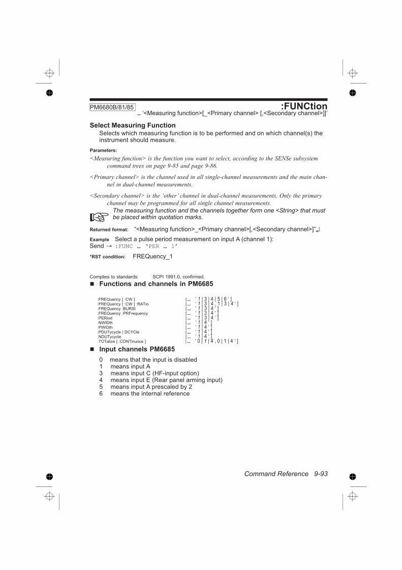
Command Reference 9-93
Functions and channels in PM6685
:FREQuency [ :CW ] [ ‘ 1 | 3 | 4 | 5 | 6 ‘ ]:FREQuency [ :CW ] :RATio [ ‘ 1 | 3 | 4 , 1 | 3 | 4 ‘ ]:FREQuency :BURSt [ ‘ 1 | 3 | 4 ‘ ]:FREQuency :PRFrequency [ ‘ 1 | 3 | 4 ‘ ]:PERiod [ ‘ 1 | 3 | 4 ‘ ]:NWIDth [ ‘ 1 | 4 ‘ ]:PWIDth [ ‘ 1 | 4 ‘ ]:PDUTycycle | DCYCle [ ‘ 1 | 4 ‘ ]:NDUTycycle [ ‘ 1 | 4 ‘ ]:TOTalize [ :CONTinuous ] [ ‘ 0 | 1 | 4 , 0 | 1 | 4 ‘ ]
Input channels PM6685
0 means that the input is disabled1 means input A3 means input C (HF-input option)4 means input E (Rear panel arming input)5 means input A prescaled by 26 means the internal reference
:FUNCtionPM6680B/81/85 ‘<Measuring function>[_<Primary channel> [,<Secondary channel>]]’
Select Measuring FunctionSelects which measuring function is to be performed and on which channel(s) theinstrument should measure.
Parameters:
<Measuring function> is the function you want to select, according to the SENSe subsystem
command trees on page 9-85 and page 9-86.
<Primary channel> is the channel used in all single-channel measurements and the main chan-
nel in dual-channel measurements.
<Secondary channel> is the ‘other’ channel in dual-channel measurements. Only the primary
channel may be programmed for all single channel measurements.
The measuring function and the channels together form one <String> that mustbe placed within quotation marks.
Returned format: “<Measuring function>_<Primary channel>[,<Secondary channel>]”
Example Select a pulse period measurement on input A (channel 1):Send :FUNC ‘PER 1’
*RST condition: FREQuency_1
Complies to standards: SCPI 1991.0, confirmed.

9-94 Command Reference
Input channels PM6680B and PM6681
1 means input A
2 means input B
3 means input C (HF-input option)
4 means input E (Rear panel arming input)
5 means input A prescaled by 2
6 means the internal reference
7 means input A with the variable hysteresis mode
Functions and channels in PM6680B and PM6681
:FREQuency [ :CW ] [ ‘ ( 1 | 2 3 | 4 | 5 | 6 | 7 ) ‘ ]:FREQuency [ :CW ] :RATio [ ‘ 1 | 2 | 3 | 4 , 1 | 2 | 3 | 4 ‘ ]:FREQuency :BURSt [ ‘ 1 | 2 | 3 | 4 | 5 | 6 | 7 ‘ ]:FREQuency :PRF [ ‘ 1 | 2 | 3 | 4 | 5 | 6 | 7 ‘ ]
:PERiod [ ‘ 1 | 2 | 3 | 4 | 5 | 6 | 7 ‘ ]
:TINTerval [ ‘ 1 | 2 | 4 , 1 | 2 | 4 | 6 ‘ ]:PHASe [ ‘ 1 | 2 | 6 , 1 | 2 | 6 ‘ ]
:NWIDth [ ‘ 1 | 2 | 4 | 6 ‘ ]:PWIDth [ ‘ 1 | 2 | 4 | 6 ‘ ]
:DCYCle | PDUTycycle [ ‘ 1 | 2 | 4 | 6 ‘ ]:NDUTycycl [ ‘ 1 | 2 | 4 | 6 ‘ ]
:RISE:TIME [ ‘ 1 | 2 ‘ ]:FALL:TIME [ ‘ 1 | 2 ‘ ]
:VOLT:MAXimum [ ‘ 1 | 2 ‘ ]:VOLT:MINimum [ ‘ 1 | 2 ‘ ]:VOLT:PTPeak [ ‘ 1 | 2 ‘ ]
:TOTalize:GATed [ ‘ 1 | 2 | 4 | 6, 1 | 2 | 4 | 6 ‘ ]:TOTalize:TIMed [ ‘ 1 | 2 | 4 | 6, 1 | 2 | 4 | 6 ‘ ]:TOTalize:ACCumulated [ ‘ 1 | 2 | 4 | 6, 1 | 2 | 4 | 6 ‘ ]:TOTalize:SSTop [ ‘ 1 | 2 | 4 | 6 , 1 | 2 | 4 | 6 ‘ ]

Command Reference 9-95
:INTernal :FORMatPM6680B/81/85«REAL|PACKed»
Internal FormatThis command selects the internal data format of the measurement result from theSENSe block. The purpose of the command is to increase the measurementspeed.
Parameters:
REAL means that the result is calculated in real-time after each measurement.
PACKed means that the raw measurement data is stored internally and the result is not calcu-
lated in real-time between measurements. The results are calculated later when they are
sent to the controller. Since the result is not calculated, other blocks cannot use this
data. That means that you cannot have the DISPlay, OUTPut, and CALCulate blocks
switched on when using PACKed format.
The following measuring functions in PM6680B/81 cannot be used with PACKedformat: Phase, Duty Cycle and Volt.
PM6685 cannot used PACKed format with Duty Cycle.
The internal format affects the number measuring results that the measurement re-sult buffer can hold.
Format Measuring Function
Number of Results in
Buffer
PM6680B/85 PM6681
Real: All functions 2048 7019
Packed: Frequency, Period, Ratio Totalize 2166 6143
Pulse Width, Time-Interval, Rise/Fall time 764 4466
Phase, Duty Cycle, Volt N.A. N.A.
Low resolution Frequency and Period N.A. 8191
Low Res. Time-Interval and Pulse Width N.A. 4095
You must consider this when fetching results with the :FETCh:ARRay query.
*RST condition: REAL

9-96 Command Reference
:ROSCillator :SOURce PM6680B/81/85 «INT|EXT»
Select Reference OscillatorSelects the signal from the external reference input as timebase instead of the in-ternal timebase oscillator.
Returned format: <INT|EXT>
*RST condition: INT
Complies to standards: SCPI 1991.0, confirmed.
:SDELay PM6685 «<Numeric value>|MIN|MAX»
BURST/PRF Synchronization DelaySets the synchronization delay time used in FREQuency:BURSt | PRF measure-ments.
Parameter range: 200 ns to 1.6777215 s
*RST condition: 10 ms

Command Reference 9-97
:TOTalize :GATEPM6680B/81/85 <Boolean>
Gate On/OffOpen/closes the gate for :TOTalize[:CONTinuous].
Before opening the gate with this command, the counter must be in the ‘contin-uously initiated’ state , (:INIT:CONT ON)or else the totalizing will not start.
Parameters: <Boolean> = (1 / ON | 0 / OFF)
Returned format: <Boolean>
Example:
Send :FUNC ‘TOT 1’ Selects totalizingon input A
Send :INIT:CONT ON;TOT:GATE ONThis will initiate totalizing, reset the totalizing value to zero, and start totalizing.
Send TOT:GATE OFF Stop totalizingRead :FETCh:ARRay? -1 Read the final result
*RST condition: OFF
:VOLTage:GATed:STATePM6680B PM6681 <Boolean>
Gated Voltage MeasurementSelects the gated mode for the :VOLTage:MAX|MIN|PTPeak measuring func-tions and for the Autotrigger function.
The gated mode is useful for removing overshoot and undershoot. The gate signalis controlled by the :ARM:STOP:SLOPe and :ARM:STOP:SOURce commands. Ifchannel 2 (B) is the source for the gating signal, all other characteristics of thatchannel can be used. When Gated Voltage is selected, the Stop Arming function isdisabled from its normal stop arming usage. When gated voltage mode is selected,high enables measurement and low disables measurements. Use the slope if youwant it the other way around.
Parameters:
<Boolean> = 1/ON|0/OFF
Returned format: 1|0 *RST condition: OFF

9-98 Command Reference
This page is intentionally left blank.

Command Reference 9-99
Status Subsystem
:STATus
:DREGister0
:ENABle <bit mask>[:EVENt]?
:OPERation
:CONDition?
:ENABle <bit mask>[:EVENt]?
:QUEStionable
:CONDition?
:ENABle <bit mask>[:EVENt]?
:PRESet
Related Common Commands:
*CLS
*ESE <bit mask>*ESR?
*PSC <bit mask>*SRE <bit mask>*STB?

9-100 Command Reference
:STATus :DREGister0?80B/81/85
Read Device Status Event RegisterThis query reads out the contents of the Device Event Register. Reading the De-vice Event Register clears the register. See Figure 6-14.
Returned format:
<dec.data> = the sum (between 0 and 6) of all bits that are true. See table below:
Bit No. Weight Condition
2 4 Last measurement below low limit.
1 2 Last measurement above high limit.
:STATus :DREGister0 :ENABle80B/81/85
<bit mask>
Enable Device Status ReportingThis command sets the enable bit of the Device Register 0.
Parameters:
<dec.data> = the sum (between 0 and 6) of all bits that are true. See table below:
Bit No. Weight Condition
2 4 Enable monitoring of low limit
1 2 Enable monitoring of high limit
Returned format: <bit mask>

Command Reference 9-101
:STATus :OPERation :CONDition?80B/81/85
Read Operation Status Condition RegisterReads out the contents of the operation status condition register. This register re-flects the state of the measurement process. See figure below. Note that bits 0 to3, 7, and 9 to 15 are not used.
Returned Format:
<Decimal data> = the sum (between 0 and 368) of all bits that are true. See table below:
Bit No. Weight Condition
8 256 Not Measurement
6 64 Waiting for bus arming
5 32 Waiting for triggering and/ or external arming
4 16 Measurement
Complies to standards: SCPI 1991.0, confirmed

9-102 Command Reference
:STATus :OPERation :ENABle80B/81/85
<Decimal data>
Enable Operation Status ReportingSets the enable bits of the operation status enable register. This enable registercontains a mask value for the bits to be enabled in the operation status event reg-ister. A bit that is set true in the enable register enables the corresponding bit inthe status register. See figure on page 9-101.
An enabled bit will set bit #7, OPR (Operation Status Bit), in the Status Byte Regis-ter if the enabled event occurs. See also status reporting on page 3-14.
Power-on will clear this register if power-on clearing is enabled via *PSC.
Parameters: <dec.data> = the sum (between 0 and 368) of all bits that are true. See ta-ble below:
Bit No. Weight Condition
8 256 No measurement
6 64 Waiting for bus arming
5 32 Waiting for triggering and/or external arming
4 16 Measurement
Returned Format: <Decimal data>
Example:
SEND :STAT:OPER:ENAB 288In this example, waiting for triggering, bit 5, and Measurement stopped, bit 8, willset the OPR-bit of the Status Byte. (This method is faster than using *OPC if youwant to know when the measurement is ready.)
Complies to standards: SCPI 1991.0, confirmed.

Command Reference 9-103
:STATus:OPERation?
80B/81/85
Read Operation Status, EventReads out the contents of the operation event status register. Reading the Opera-tion Event Register clears the register. See figure on page 9-101.
Returned Format: <Decimal data>
<dec.data> = the sum (between 0 and 368) of all bits that are true. See table on page 9-102.
Complies to standards: SCPI 1991.0, confirmed.
:STATus :PRESetPM6680B/81/85
Enable Device Status ReportingThis command has an SCPI standardized effect on the status data structures. Thepurpose is to precondition these toward reporting only device-dependent statusdata.
– It only affects enable registers. It does not change event and condition registers.
– The IEEE-488.2 enable registers, which are handled with the common commands *SRE and
*ESE remain unchanged.
– The command sets or clears all other enable registers. Those relevant for this counter are as
follows:
– It sets all bits of the Device status Enable Registers to 1.
– It sets all bits of the Questionable Data Status Enable Registers and the Operation Status En-
able Registers to 0.
– The following registers never change in the counter, but they do conform to the standard
:STATus:PRESet values.
– All bits in the positive transition filters of Questionable Data and Operation status registers
are 1.
– All bits in the negative transition filters of Questionable Data and Operation status registers
are 0.
Complies to standards: SCPI 1991.0, confirmed.

9-104 Command Reference
:STATus :QUEStionable :CONDition?PM6680B/81/85
Read Questionable Data/Signal Condition RegisterReads out the contents of the status questionable condition register.
Returned Format:
<dec.data> = the sum (between 0 and 17920) of all bits that are true. See table below:
Bit No. Weight Condition
14 16384 Unexpected parameter
10 1024 Timeout or no signal detected
9 512 Overflow
Complies to standards: SCPI 1991.0, confirmed.

Command Reference 9-105
:STATus :QUEStionable?PM6680B/81/85
Read Questionable Data/Signal Event RegisterReads out the contents of the status questionable event register. Reading theStatus Questionable Event Register clears the register. See figure on page 9-104.
Returned Format:
<dec.data> = the sum (between 0 and 17920) of all bits that are true. See the table on page
9-104.
Complies to standards: SCPI 1991.0, confirmed.
:STATus :QUEStionable :ENABlePM6680B/81/85
<Decimal data>
Enable Questionable Data/Signal Status ReportingSets the enable bits of the status questionable enable register. This enable registercontains a mask value for the bits to be enabled in the status questionable eventregister. A bit that is set true in the enable register enables the corresponding bit inthe status register. See figure on page 9-104.
An enabled bit will set bit #3, QUE (Questionable Status Bit), in the Status ByteRegister if the enabled event occurs. See also status reporting on page 3-14.
Power-on will clear this register if power-on clearing is enabled via *PSC.
Parameters:
<dec.data> = the sum (between 0 and 17920) of all bits that are true. See the table on page
9-104.
Returned Format: <Decimal data>
Example:
Send :STAT:QUES:ENAB 16896
In this example, both ‘unexpected parameter’ bit 14, and ‘overflow’ bit 8, will setthe QUE-bit of the Status Byte when a questionable status occurs.
Complies to standards: SCPI 1991.0, confirmed.

9-106 Command Reference
This page is intentionally left blank.

Command Reference 9-107
:TIME <timeout value>:UNPRotect
:VERSion?
Related common command:
*IDN?
*OPT?
*PUD <arbitrary block program data>*RST
System Subsystem
:SYSTem
:COMMunicate
:GPIB
:ADDRess <Numeric value> | MIN | MAX:ERRor?
:PRESet
:SYSTem:SDETect[:ENABle] ON | OFF (Only PM6685):SET <Block data>:TIME
:ELAPsed?
:TOUT
[:STATe] ON | OFF

9-108 Command Reference
:SYSTem :COMMunicate: GPIB: ADDRess 80B/81/85 «<Numeric value>|MAX|MIN» [,«<Numeric value>|MAX|MIN»]
Set GPIB AddressThis command sets the GPIB address. This selection overrides the switches onthe rear panel of the counter. The set address is valid until a new address is set,either by bus command, switch setting, or via the front panel AUX-MENU.
Parameters:
<Numeric value> is a number between 0 and 30.MIN sets address 0.MAX sets address 30.[,<Numeric value>|MAX|MIN] sets a secondary address. This is accepted but notused in PM6681 and PM6685. PM6680B does not accept a secondary address.
[:SELF] This optional parameter is accepted by PM6681 and PM6685.PM6680B does not accept [:SELF].
Returned format:> <Numeric value>
Example:
SEND :SYST:COMM:GPIB:ADDR 12
This example sets the bus address to 12.
Complies to standards: SCPI 1991.0, confirmed.
:SYSTem :ERRor? PM6680B/81/85
Queries for an ASCii text description of an error that occurred. The error mes-sages are placed in an error queue, with a FIFO (First In-First Out) structure. Thisqueue is summarized in the Error AVailable (EAV) bit in the status byte.
Returned format:
<error number>,"<Error Description String>"
Where:
<Error Description String> = an error description as ASCii text.
See also: Chapter 8, error messages.
Complies to standards: SCPI 1991.0, confirmed.

Command Reference 9-109
:SYSTem :PRESetPM6680B/81/85
PresetThis command sets the counter to the same default settings as when the frontpanel key LOCAL/PRESET is pressed in local mode.
These are not exactly the same settings as after *RST,SYST:PRES gives 200 ms Measurement Time and signal detection ON, while*RST gives 10-ms Measurement Time and signal detection OFF.
See also: Default settings on page -.
Complies to standards: SCPI 1991.0, confirmed.
:SYSTem :SDETectPM6685 <Boolean>
Signal DetectionThis command switches on or off the signal detection, that is, the ability to showNO SIGNAL, NO TRIG on the display.
When signal detection is enabled, the measurement attempt will be abandonedwhen the no signal is detected. A zero result will be sent to the controller instead ofa measurement result, and the timeout bit in the STATus QUEStionable registerwill be set.
Returned format: «0|1»
Where:
0 means no signal detection
1 means signal detection ON.
*RST condition: 0

9-110 Command Reference
:SYSTem :SET PM6680B/81/85 <Block data>
Read or Send SettingsTransmits in binary form the complete current state of the instrument. This datacan be sent to the instrument to later restore this setting. This command has thesame function as the *LRN? common command with the exception that it returnsthe data only as response to :SYST:SET?. The query form of this command re-turns a definite block data element.
Parameters:
<Block data> is the instrument setting previously retrieved via the :SYSTem:SET? query.
Returned format: <Block data>
Where:
<Block data> is #292<92 data bytes> for PM6680B
<Block data> is #3104<104 data bytes> for PM6681
<Block data> is #276<76 data bytes> for PM6685
SEND :SYST:SET?READ #2764...- . .Çä......d...
+.................-.c-.............. ?..............d
Complies to standards: SCPI 1991.0, confirmed.
:SYSTem :TIME :ELAPsed? PM6680B/81/85
Read On-timeUse this command if you want to know (in seconds) how long the counter hasbeen on.
Returned format:
<String>=Power-on time.
For PM6680B and PM6685, this is the time elapsed since the last power-on.
For PM6681, this is the total elapsed time since the counter was new.

Command Reference 9-111
:SYSTem :TOUTPM6680B/81/85 <Boolean>
Timeout On/OffThis command switches on or off the timeout. When timeout is enabled, the mea-surement attempt will be abandoned when the time set with :SYST:TOUT:TIMEhas elapsed. A zero result will be sent to the controller instead of a measurementresult and the timeout bit in the STATus QUEStionable register will be set.
Returned format: 0 means no timeout; 1 means that the timeout set by :SYS-Tem:TOUT:TIME is used.
Example:
SEND :SYST:TOUT 1;TOUT:TIME 0.5;:STAT:QUES:ENAB
1024;:*SRE 8This example turns on timeout, sets the timeout to 0.5 s, enables status reporting ofquestionable data at timeout, and enables service request on questionable data.
SEND *STB? If bit 3 in the status byte is set, read thequestionable data status.
SEND :STAT:QUES:EVEN? This query reads the ques-tionable data status.
READ «1024|0» 1024 means timeout has occurred, and 0means no timeout.
*RST condition: 0
:SYSTem :TOUT :TIMEPM6680B/81/85 «<Numeric value>|MIN|MAX»
Timeout, SetThis command sets the timeout in seconds.
The timeout starts when a measurement starts and, if no result is obtained whenthe set timeout has elapsed the measurement is terminated.
Note that you must enable timeout using :SYST:TOUT_ON for this setting to takeeffect.
Parameters:
<Numeric value> is the timeout in seconds. The range is 0.1 to 25.5 s for PM6680B and
PM6685. The range is 64 ms to 400 s for PM6681
MIN gives 0.1 s (64 ms for PM6681)
MAX gives 25.5 s (400 s for PM6681)
Returned format: <Numeric value>
*RST condition: 0.1 (6.4E-2 for PM6681)
Complies to standards: SCPI 1991.0, confirmed.

9-112 Command Reference
:SYSTem :UNPRotect PM6680B/81/85
UnprotectThis command will unprotect the user data (set/read by *PUD) and front settingmemories 10-19 until the next PMT (Program message terminator) or Device clearor Reset (*RST). This makes it necessary to send an unprotect command in thesame message as for instance *PUD.
Example
Send :SYST:UNPR; *PUD #240Calibrated 1992-11-17, inven-tory No.1234
Where:
# means that <arbitrary block program data> will follow.
2 means that the two following digits will specify the length of the data block
40 is the number of characters in this example
:SYSTem :VERSion? PM6680B/81/85
System VersionThis query returns the SCPI system version that this instrument complies to.
Returned format:
<year>.<revision>
Where <year> is the year of publication of the complied standard and <revision> isthe number of the SCPI standard.
Example
Send :SYST:VER?Read 1991.0
Complies to standards: SCPI 1991.0, confirmed.

Command Reference 9-113
Test Subsystem
:TEST
:CHECk ON | OFF:SELect RAM | ROM | LOGic | DISPlay | ALL
Related common command:
*TST

9-114 Command Reference
:TEST:CHECk PM6680B/81/85 <Boolean>
Select Check signalThis command connects the internal reference signal to the measuring logic, in-stead of an external measuring signal. This makes it possible to test all functions.
The frequency of the reference is 10 MHz for PM6680B and PM6685, and100 MHz for PM6681.
Parameters:
<Boolean> = 1 / ON | 0 / OFF
1 and ON means test signal connected
0 and OFF means test signal disconnected.
Selecting channel 6 when entering measuring channel for :CONFigure :MEA-Sure, etc., also selects the reference.
Returned format: 1|0
*RST condition: 0
:TEST :SELect PM6680B/81/85 «RAM | ROM | LOGic | DISPlay | ALL»
Select Self-testsSelects which internal self-tests shall be used when self-test is requested by the*TST command.
Returned format:
«RAM | ROM | LOGic | DISPlay | ALL»
*RST condition: ALL

Command Reference 9-115
Trigger Subsystem
:TRIGger
[ STARt / :SEQuence [ 1 ] ]
[ :LAYer [ 1 ] ]
:COUNt <Numeric value> | MIN | MAX
Related common command:*TRG

9-116 Command Reference
:TRIGger:COUNt PM6680B/81/85 «<Numeric value> | MIN | MAX»
No. of Triggerings on each Ext Arm startSets how many measurements the instrument should make for each ARM:STARtcondition, (block arming).
These measurements are done without any additional arming conditions beforethe measurement. This also means that stop arming is disabled for the measure-ments inside a block.
The actual number of measurements made on each INIT equals to:(:ARM:START:COUN)*(:TRIG:START:COUNT)
Parameters:
<Numeric value> is a number between 1 and 65535.
MAX gives 65535
MIN gives 1
Example:
SEND :TRIG:COUN 50
Returned format: <Numeric value>
*RST condition: 1
Complies to standards: SCPI 1991.0, confirmed.

Command Reference 9-117
Common Commands
*CLS
*DMC <Macro label> , <Program messages>*EMC <Decimal data>*ESE <Decimal data>*ESR?
*GMC? <Macro label>*IDN?
*LMC?
*LRN?
*OPC
*OPC?
*OPT?*PMC
*PSC <Decimal data>*PUD <Arbitrary block program data>*RCL <Decimal data>*RMC <Macro name>*RST
*SAV <Decimal data>*SRE <Decimal data>*STB?
*TRG
*TST?
*WAI

9-118 Command Reference
*CLS PM6680B/81/85
Clear Status CommandThe *CLS common command clears the status data structures by clearing all eventregisters and the error queue. It does not clear enable registers and transition fil-ters. It clears any pending *WAI, *OPC, and *OPC?.
Example:
Send *CLS
Complies to standards: IEEE 488.2 1987.

Command Reference 9-119
DMCPM6680B/81/85 <Macro label> , <Program messages>
Define MacroAllows you to assign a sequence of one or more program message units to amacro label. The sequence is executed when the macro label is received as acommand or query. Twenty five macros can be defined at the same time, and eachmacro can contain an average of 40 characters.
If a macro has the same name as a command, it masks out the real command withthe same name when macros are enabled. If macros are disabled, the originalcommand will be executed.
If you define macros when macro execution is disabled, the counter executes the*DMC command fast, but if macros are enabled, the execution time for this com-mand is longer.
Parameters:
<Macro label> = 1 to 12-character macro label. (String data must be surrounded by “ ” or ‘ ‘
as in the example below.)
<Program messages> = the commands to be executed when the macro label is received, both
block data and string data formats can be used.
Example 1:
SEND *DMC ‘AMPLITUDE?’,":FUNC ‘FREQ 1’;:INP:HYST:AUTO ONCE ;:INP:HYST?;:INP:LEV?"
This example defines a macro called amplitude?.
SEND AMPLITUDE?The macro makes an AUTO ONCE and reads out the hysteresis and trigger levelthat auto selects. (Macros must be enabled; otherwise, the :AMPLITUDE? querywill not execute, see EMC)).
READ +3.46125461E-001;+3.64852399E-001Auto selects 33% of Vpp as hysteresis, so multiplying the first part of this readingby 3 will give you the signal amplitude (0.346*3=1.04 V in this example). You can
also calculate positive peak voltage:Hysteresis
Trigger Level* 3
2 and negative
peak voltage: VpHysteresis
Trigger Level* 3
2
Example 2:
SEND *DMC ‘AUTOFILT’,":INP:HYST:AUTO $1;:INP:FILT $1This example defines a macro AUTO which takes one argument, i.e., auto«ON|OFF|ONCE» ($1) .
SEND AUTOFILT OFFTurns off both the auto function and the filter.
Complies to standards: IEEE 488.2 1987.

9-120 Command Reference
*EMC PM6680B/81/85 <Decimal data>
Enable MacrosThis command enables and disables expansion and execution of macros. If mac-ros are disabled, the instrument will not recognize a macro although it is defined inthe instrument. (The Enable Macro command takes a long time to execute.)
Parameters:
<Decimal data> = is 0 or 1. A value which rounds to 0 turns off macro execution. Any other
value turns macro execution on.
Note that 1 or 0 is <Decimal data>, not <Boolean>!ON|OFF is not allowed here!
Returned format: «0|1» 1 indicates that macro expansion is enabled.0 indicates that macro expansion is disabled.
Example:
SEND*EMC 1
Enables macro expansion and execution.
Complies to standards: IEEE 488.2 1987.

Command Reference 9-121
*ESEPM6680B/81/85
<Decimal data>
Standard Event Status EnableSets the enable bits of the standard event enable register. This enable registercontains a mask value for the bits to be enabled in the standard event status regis-ter. A bit that is set true in the enable register enables the corresponding bit in thestatus register. An enabled bit will set the ESB (Event Status Bit) in the Status ByteRegister if the enabled event occurs. See also status reporting on page 3-14.
Parameters: <dec.data> = the sum (between 0 and 255) of all bits that are true.
Event Status Enable Register (1 = enable)
Bit Weight Enables
7 128 PON, Power-on occurred
6 64 URQ, User Request
5 32 CME, Command Error
4 16 EXE, Execution Error
3 8 DDE, Device Dependent Error
2 4 QYE, Query Error
1 2 RQC, Request Control (not used)
0 1 Operation Complete
Returned Format: <Decimal data> Example:
SEND *ESE 36In this example, command error, bit 5, and query error, bit 2, will set the ESB-bit ofthe Status Byte if these errors occur.
Complies to standards: IEEE 488.2 1987.
Figure 9-3 Bits in the standard event status register.

9-122 Command Reference
∗ESR?PM6680B/81/85
Event Status RegisterReads out the contents of the standard event status register. Reading the Stan-dard Event Status Register clears the register.
Returned Format:
<dec.data> = the sum (between 0 and 255) of all bits that are true. See table on page 9-121.
Complies to standards: IEEE 488.2 1987.
*GMC? PM6680B/81/85 < macro label>
Get Macro DefinitionThis command makes the counter respond with the current definition of the givenmacro label.
Parameters:
<Macro label> = the label of the macro for which you want to see the definition. (String data
must be surrounded by “ ” or ‘ ‘ as in the example below.)
Returned Format: <Block data>
Example:
SEND *GMC? ‘AMPLITUDE?’Gives a block data response, for instance:
READ#255:FUNC ‘FREQ 1’;:INP:HYST:AUTO ONCE;:INP:HYST?;INP:LEV?
Complies to standards: IEEE 488.2 1987.

Command Reference 9-123
*IDN?PM6680B/81/85
Identification queryReads out the manufacturer, model, serial number, Firmware level for main andGPIB program in an ASCii response data element. The query must be the lastquery in a program message.
Response is <Manufacturer> , <Model> , <Serial Number>, <Firmware Level>.
<Serial number> is not implemented in PM6680B and PM6685 and will always re-turn a zero. Please look at the type plate at the rear panel of the counter if you areinterested in the serial number. PM6681 returns the correct serial number.
Example
SEND *IDN?READ Fluke, PM6685, 0, MAIN V1.01 19 Nov
1992 / GPIB V1.12 28 Oct 1992
Complies to standards: IEEE 488.2 1987.
*LMC?PM6680B/81/85
Learn MacroMakes the instrument send a list of string data elements, containing all macro la-bels defined in the instrument.
Returned Format:
<String> ,<String>
<String> = a Macro label. (String data will be surrounded by “ ” as in the example below.)
Example:
SEND *LMC?May give the following response:
READ“AUTOFILT”,"AMPLITUDE?"
Complies to standards: IEEE 488.2 1987.

9-124 Command Reference
*LRN? PM6680B/81/85
Learn Device SetupLearn Device Setup Query. Causes a response message that can be sent to theinstrument to return it to the state it was in when the *LRN? query was made.
Returned Format:
:SYST:SET_<Block data>
Where:
<Block data> is #292<92 data bytes> for PM6680B
<Block data> is #3104<104 data bytes> for PM6681
<Block data> is #276<76 data bytes> for PM6685
Example
SEND *LRN?
Complies to standards: IEEE 488.2 1987.
*OPC PM6680B/81/85
Operation CompleteThe Operation Complete command causes the device to set the operation com-plete bit in the Standard Event Status Register when all pending selected deviceoperations have been finished. See also Example 4 in Chapter 4.
Example:
Enable OPC-bitSEND *ESE 1
Start measurement (INIT). *OPC will set the operation complete bit in the status register when themeasurement is done.SEND :INIT;*OPC
Wait 1s for the measurement to stop. Read serial poll register, will reset service requestSPOLL
Check the Operation complete bit (0) in the serial poll byte. If it is true the measurement iscompleted and you can fetch the result.SEND FETCh?
Then read the event status register to reset it:SEND *ESR?
If bit 0 is false, abort the measurement.SEND :ABORt
Complies to standards: IEEE 488.2 1987.

Command Reference 9-125
*OPC?PM6680B/81/85
Operation Complete QueryOperation Complete query. The Operation Complete query places an ASCii char-acter 1 into the device’s Output Queue when all pending selected device opera-tions have been finished.
Returned Format: 1
See also:
Example 6 is Chapter 4.
Complies to standards: IEEE 488.2 1987.
*OPT?PM6680B/81/85
Option IdentificationResponse is a list of all detectable options present in the instrument, with absentoptions represented with an ASCii ‘0’.
Returned format:
<Bus option>,<Prescaler option>
Where:
<Bus option> = GPIB
<Prescaler option> = 0|10|20
0 for prescaler option means that no prescaler is installed.
Oscillator type are not detectable and can therefore, not be reported.
Complies to standards: IEEE 488.2 1987.

9-126 Command Reference
*PMC PM6680B/81/85
Purge MacrosRemoves all macro definitions.
Example: *PMC
See also:
:MEMory:DELete:MACRo ‘<Macro-name>’ if you want to remove a singlemacro.
Complies to standards: IEEE 488.2 1987.
*PSC PM6680B/81/85 <Decimal data>
Power-on Status ClearEnables/disables automatic power-on clearing. The status registers listed beloware cleared when the power-on status clear flag is 1. Power-on does not affect theregisters when the flag is 0.
– Service request enable register (*SRE)
– Event status enable register (*ESE)
– Operation status enable register (:STAT:OPER:ENAB)
– Questionable data/signal enable register (:STAT:QUES:ENAB)
– Device enable registers (:STAT:DREG0:ENAB)
– *RST does not affect this power-on status clear flag.
Parameters: <Decimal data> = a number that rounds to 0 turns off automatic power-onclearing. Any other value turns it on.
Returned Format: «1 | 0»
1 is enabled and 0 is disabled.
Example: *PSC 1This example enables automatic power-on clearing.
Complies to standards: IEEE 488.2 1987.

Command Reference 9-127
*PUDPM6680B/81/85 <Arbitrary block program data>
Protected User DataProtected user data. This is a data area in which the user may write any data up to64 characters. The data can always be read, but you can only write data after un-protecting the data area. A typical use would be to hold calibration information, us-age time, inventory control numbers, etc.
The content at delivery is: #234 FACTORY CALIBRATED ON: 19YY-MM-DD
– YY = year, MM = month, DD = day
Returned format: <Arbitrary block response data>– Where:
<arbitrary block program data> is the data last programmed with *PUD.
Example
Send :SYST:UNPR; *PUD #240Calibrated 1993-07-16, inven-tory No.1234
# means that <arbitrary block program data> will follow.
2 means that the two following digits will specify the length of the data block.
40 is the number of characters in this example.
Complies to standards: IEEE 488.2 1987.
*RCLPM6680B/81/85 <Decimal data>
RecallRecalls one of the up to 20 previously stored complete instrument settings from theinternal nonvolatile memory of the instrument.
Memory number 0 contains the power-off settings for PM6685. For PM6681 mem-ory number 0 contains the power-off settings until PRESET is pressed. After pre-set, memory 0 contains the pre-preset settings.
Parameters:
<Decimal data> = a number between 0 and 19.
Example:
SEND *RCL 10
Complies to standards: IEEE 488.2 1987.

9-128 Command Reference
∗RMC PM6680B/81/85 ‘<Macro name>’
Delete one MacroThis command removes an individual MACRo.
Parameters:
‘<Macro name>’ is the name of the macro you want to delete.
<Macro name> is String data that must be surrounded by quotation marks.
See also:
*PMC, if you want to delete all macros.
*RST PM6680B/81/85
ResetThe Reset command resets the counter. It is the third level of reset in a 3-level re-set strategy, and it primarily affects the counter functions, not the IEEE 488 bus.
The counter settings will be set to the default settings listed on page -. All previouscommands are discarded, macros are disabled, and the counter is prepared tostart new operations.
Example: *RST
See also:
Default settings on page -.
Complies to standards: IEEE 488.2 1987.

Command Reference 9-129
*SAVPM6680B/81/85_ <Decimal data>
SaveSaves the current settings of the instrument in an internal nonvolatile memory.Nineteen memory locations are available. Switching the power off and on does notchange the settings stored in the registers.
Note that memory positions 10 to 19 can be protected from the front panel auxiliarymenu. If this has been done, use the :SYSTem:UNPRotect command, then youcan alter these memory positions.
Parameters
<Decimal data> = a number between 1 and 19.
Example:
SEND *SAV 10
Complies to standards: IEEE 488.2 1987
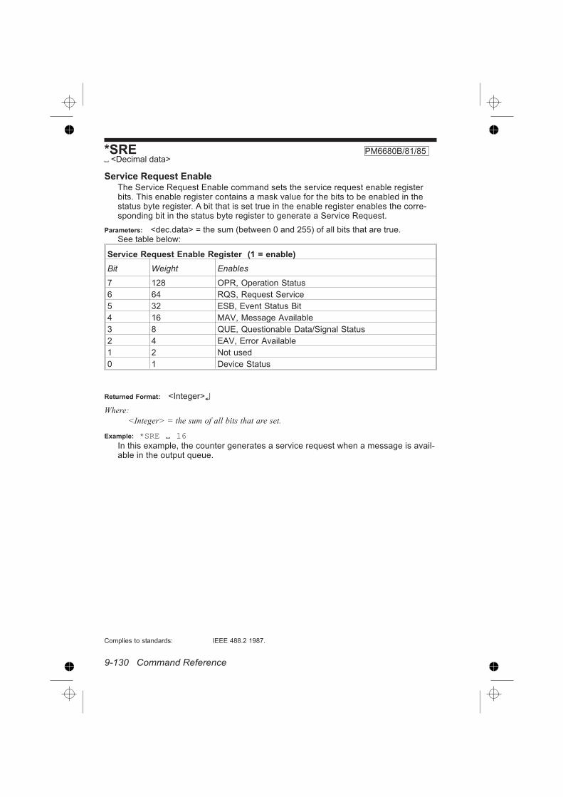
9-130 Command Reference
*SRE PM6680B/81/85 <Decimal data>
Service Request EnableThe Service Request Enable command sets the service request enable registerbits. This enable register contains a mask value for the bits to be enabled in thestatus byte register. A bit that is set true in the enable register enables the corre-sponding bit in the status byte register to generate a Service Request.
Parameters: <dec.data> = the sum (between 0 and 255) of all bits that are true.See table below:
Service Request Enable Register (1 = enable)
Bit Weight Enables
7 128 OPR, Operation Status
6 64 RQS, Request Service
5 32 ESB, Event Status Bit
4 16 MAV, Message Available
3 8 QUE, Questionable Data/Signal Status
2 4 EAV, Error Available
1 2 Not used
0 1 Device Status
Returned Format: <Integer>
Where:
<Integer> = the sum of all bits that are set.
Example: *SRE 16In this example, the counter generates a service request when a message is avail-able in the output queue.
Complies to standards: IEEE 488.2 1987.

Command Reference 9-131
*STB?PM6680B/81/85
Status Byte QueryReads out the value of the Status Byte. Bit 6 reports the Master Summary Statusbit (MSS), not the Request Service (RQS). The MSS is set if the instrument hasone or more reasons for requesting service.
Returned Format:
<Integer> = the sum (between 0 and 255) of all bits that are true. See table below:
Status Byte Register (1 = true)
Bit Weight Name Condition
7 128 OPR Enabled operation status has occurred.
6 64 MSS Reason for requesting service
5 32 ESB Enabled status event condition has occurred
4 16 MAV An output message is ready
3 8 QUE The quality of the output signal is questionable
2 4 EAV Error available
1 2 Not used
0 1 DREG0 Enabled status device event conditions haveoccurred
See also: If you want to read the status byte with the RQS bit, use serial poll.
Complies to standards: IEEE 488.2 1987.
*TRGPM6680B/81/85
TriggerThe trigger command *TRG starts the measurement and places the result in theoutput queue.
It is the same as::ARM:STARt:LAYer2:IMM; *WAI;:FETCh?
The Trigger command is the device-specific equivalent of the IEEE 488.1 definedGroup Execute Trigger, GET. It has exactly the same effect as a GET after it hasbeen received, and parsed by the counter.
However, GET is much faster than *TRG, since GET is a hardware signal that doesnot have to be parsed by the counter.
Example:
SEND :ARM:START:LAY2:SOURCE BUSSEND :INIT:CONT ONSEND *TRGREAD +3.2770536E+004
Type of Command:
Aborts all previous measurement commands if not *WAI is used.
Complies to standards: IEEE 488.2 1987.

9-132 Command Reference
*TST? PM6680B/81/85
Self Test
The self-test query causes an internal self-test and generates a response indicat-ing whether or not the device completed the self-test without any detected errors.
Returned Format: <Integer>
Where:
<Integer> = a number indicating errors according to the table below.
<Integer> =PM6680B Error PM6681, PM6685 Er-
ror
0 No error
1 RAM Failure Display Failure
2 ROM 1 Failure Logic Failure
4 Logic Failure RAM Failure
8 Display Failure Bus ROM Failure
16 Not used ROM Bank 1 Failure
32 Not used ROM Bank 2 Failure
Complies to standards: IEEE 488.2 1987
*WAI PM6680B/81/85
Wait-to-continueThe Wait-to-Continue command prevents the device from executing any furthercommands or queries until execution of all previous commands or queries hasbeen completed.
Example:
SEND:MEAS:FREQ?; *WAI;:MEAS:PDUT?
In this example, *WAI makes the instrument perform both the frequency and theDuty Cycle measurement. Without *WAI, only the Duty Cycle measurement wouldbe performed.
READ +5.1204004E+002;+1.250030E-001
Complies to standards: IEEE 488.2 1987.

Chapter 10
Index

Index
!
1 Mohm · · · · · · · · · · · · · · · · · · · · · · 9-47
50 ohms · · · · · · · · · · · · · · · · · · · · · 9-47
A
Abort · · · · · · · · · · · · · · · · · · · · · · · · · 7-4
Measurement· · · · · · · · · · · · · · · · · 9-4
AC|DC· · · · · · · · · · · · · · · · · · · · 2-2,9-44
Accumulated, totalize X gated by Y 9-70
Address
GPIB · · · · · · · · · · · · · · · · · · · · · 9-108
Switches · · · · · · · · · · · · · · · · · · · · 1-4
Analog
Filter· · · · · · · · · · · · · · · · · · · · · · · 9-45
Analog Out
Enable · · · · · · · · · · · · · · · · · · · · · 9-80
Scaling factor· · · · · · · · · · · · · · · · 9-80
Aperture · · · · · · · · · · · · · · · · · · · · · 9-87
Arbitrary block data· · · · · · · · · · · · 9-112
Arming· · · · · · · · · · · · · · · · · · · · · · · · 9-8
Bus arm mode · · · · · · · · · · · · · · · · 9-8
Delay by events · · · · · · · · · · 9-7,9-10
Event count range· · · · · · · · · 9-7,9-10
External Events before Start · 9-7,9-10
Start delay · · · · · · · · · · · · · · · · · · · 9-7
Start slope · · · · · · · · · · · · · · · · · · · 9-9
Start source · · · · · · · · · · · · · · · · · · 9-9
Stop slope · · · · · · · · · · · · · · · · · · 9-11
Stop source · · · · · · · · · · · · · · · · · 9-11
Subsystem· · · · · · · · · · · · · · · · · · · 9-5
Wait for bus · · · · · · · · · · · · · · · · · 6-23
Array· · · · · · · · · · · · · · · · · · 7-4 - 7-5,7-7
Fetch · · · · · · · · · · · · · · · · · · · · · · 9-35
ASCII
Data format · · · · · · · · · · · · · · 7-8,9-38
Fixed format · · · · · · · · · · · · · · · · 9-39
Attenuation · · · · · · · · · · · · · · · · 2-2,9-44
Auto
Attenuation · · · · · · · · · · · · · · · · · 9-44
Gated voltage mode · · · · · · · · · · 9-97
Levels selected by· · · · · · · · · · · · 9-49
Off · · · · · · · · · · · · · · · · · · · · 9-45,9-48
Once · · · · · · · · · · · · · 9-46,9-49 - 9-50
Power on clearing · · · · · · · · · · · 9-126
Sensitivity · · · · · · · · · · · · · · · · · · 9-46
Speed · · · · · · · · · · · · · · · · · · · · · 9-92
Trigger · · · · · · · · · · · · · · · · · 9-50,9-97
Trigger level· · · · · · · · · · · · · · · · · 9-49
Trigger On/Off · · · · · · · · · · · · · · · 9-49
Triggering· · · · · · · · · · · · · · · · · · · · 2-2
Auto calibration on/off· · · · · · · · · · · 9-24
Average
For a preset time · · · · · · · · · · · · · 9-91
Measurements· · · · · · · · · · · · · · · 9-92
Mode · · · · · · · · · · · · · · · · · · · · · · 9-91
On/Off · · · · · · · · · · · · · · · · · · 2-4,9-92
Sample size · · · · · · · · · · · · · · · · · 9-91
Samples· · · · · · · · · · · · · · · · · · · · 9-91
Samples in averaging · · · · · · · · · 9-91
State· · · · · · · · · · · · · · · · · · · · · · · 9-92
Average or Single? · · · · · · · · · · · · · 9-92
II

B
Back-to-back· · · · · · · · · · · · · · · · · · 7-15
Period · · · · · · · · · · · · · · · · · · 7-9,7-13
Block arming · · · · · · · · · · · · · · · · · 9-116
Block data · · · · · · · · · · · · 3-12,7-8,9-38
Block measurements · · · · · · · · · · · · 7-8
Boolean · · · · · · · · · · · · · · · · · · · · · · 3-11
Burst
Carrier Frequency · · · · · · · · · · · · 9-61
Repetition Frequency · · · · · · · · · 9-62
Synchronization (PM6685) · · · · · 9-96
Bus
Drivers · · · · · · · · · · · · · · · · · · · · · · 1-6
Bus Arm · · · · · · · · · · · · · · · · · · · · · · 9-6
Exit · · · · · · · · · · · · · · · · · · · · · · · · · 9-8
Mode · · · · · · · · · · · · · · · · · · · · · · · 9-8
On/Off · · · · · · · · · · · · · · · · · · · · · · 9-8
Override· · · · · · · · · · · · · · · · · · · · · 9-8
Bus initialization · · · · · · · · · · · · · · · 3-19
C
Calculate
Block · · · · · · · · · · · · · · · · · · · · · · · 5-3
Enable · · · · · · · · · · · · · · · · · · · · · 9-22
Mathematics · · · · · · · · · · · 9-20 - 9-21
Reading data · · · · · · · · · · · · · · · · 9-15
Real time · · · · · · · · · · · · · · · · · · · · 7-9
Subsystem· · · · · · · · · · · · · · · · · · 9-13
Calibration · · · · · · · · · · 7-8,9-112,9-127
Of Comparators · · · · · · · · · · · · · · 9-30
Of Interpolators · · · · · · · · · · · · · · 9-24
Subsystem· · · · · · · · · · · · · · · · · · 9-23
Change function fast
MEAS:MEM1? · · · · · · · · · · · · · · · · 7-5
Channel
List · · · · · · · · · · · · · · · · · · · · · · · · 3-12
Selecting · · · · · · · · · · · · · · · 6-13,9-93
Character data · · · · · · · · · · · · · · · · 3-12
Check · · · · · · · · · · · · · · · · · · · · · · · · 2-3
Check Against Lower Limit · · · · · · · 9-18
Check Against Upper Limit · · · · · · · 9-19
Check signal · · · · · · · · · · · · · · · · · 9-114
Clear Status· · · · · · · · · · · · · · · · · · 9-118
Clearing
status registers · · · · · · · · · · · · · 9-126
CME-bit· · · · · · · · · · · · · · · · · 6-21,9-121
Colon · · · · · · · · · · · · · · · · · · · · 3-8,3-10
Command
Error · · · · · · · · · · · · · · 3-4,3-17,9-121
Error (CME) · · · · · · · · · · · · · · · · · 6-21
Header · · · · · · · · · · · · · · · · · · · · · 3-10
Tree · · · · · · · · · · · · · · · · · · · · · · · 3-10
Command Error (CME)
Code list· · · · · · · · · · · · · · · · · · · · · 8-2
Command tree · · · · · · · · · · · · · · · · · 3-8
Commands · · · · · · · · · · · · · · · · · · · 3-20
*CLS · · · · · · · · · · · · · · · · · 3-20,9-118
*DMC· · · · · · · · · · · · 3-13,9-117,9-119
*EMC· · · · · · · · · · · · · · · · · 3-14,9-120
*ESE · · · · · · · · · · · · · · · · 9-117,9-121
*ESR? · · · · · · · · · · · · · · · · · · · · 9-122
*GMC?· · · · · · · · · · · · · · · · 3-15,9-122
*IDN? · · · · · · · · · · · · · · · · · · · · · 9-123
*LMC · · · · · · · · · · · · · · · · 9-117,9-123
*LMC? · · · · · · · · · · · · · · · · · · · · · 3-15
*LRN? · · · · · · · · · · · · · · · · · · · · 9-124
*OPT? · · · · · · · · · · · · · · · · · · · · 9-125
*PMC· · · · · · · · · · · · 3-14,9-117,9-126
*PSC · · · · · · · · · · · · · · · · 9-117,9-126
*RCL · · · · · · · · · · · · · · · · · · · · · 9-127
*RST · · · · · · · · · · · · · · · · · · · · · 9-117
*SRE · · · · · · · · · · · · · · · · · 6-17,9-130
*STB? · · · · · · · · · · · · · · · 9-117,9-131
*TRG · · · · · · · · · · · · · · 6-29,9-8,9-131
*TST? · · · · · · · · · · · · · · · 9-117,9-132
*WAI· · · · · · · · · · · · · · · · · · · · · · 9-132
:ABORt· · · · · · · · · · · · · · · · · · · · · · 9-4
:ACQuisition:APERture · · · · · · · · 9-87
:Acquisition:HOFF · · · · · · · · · · · · 9-88
:Acquisition:HOFF:ECOunt · · · · · 9-88
:Acquisition:HOFF:MODE · · · · · · 9-89
III

:Acquisition:HOFF:TIMe · · · · · · · 9-89
:Acquisition:RESolution· · · · · · · · 9-90
:ARM · · · · · · · · · · · · · · · · · · · · · · · 9-8
:ARM:LAYer2:SOURce · · · · · · · · · 9-8
:ARM:SEQuence:LAYer1:COUNt · 9-6
:ARM:SEQuence:LAYer1:DELay· · · · · · · · · · · · · · · · · · · · · · · · 9-7,9-10
:ARM:SEQuence:LAYer1:SOURce 9-9
:ARM:SEQuence1:LAYer1:ECOunt· · · · · · · · · · · · · · · · · · · · · · · · 9-7,9-10
:ARM:SEQuence1:LAYer1:SLOPe 9-9
:ARM:SEQuence2:SLOPe · · · · · 9-11
:ARM:SEQuence2:SOURce · · · · 9-11
:ARM:STARt · · · · · · · · · · · · · · · · · 9-8
:ARM:STARt:LAYer1:COUNt· · · · · 9-6
:ARM:STARt:LAYer1:DELay · 9-7,9-10
:ARM:STARt:LAYer1:ECOunt 9-7,9-10
:ARM:STARt:LAYer1:SLOPe· · · · · 9-9
:ARM:STARt:LAYer1:SOURce · · · 9-9
:ARM:STOP:SLOPe · · · · · · · · · · 9-11
:ARM:STOP:SOURce · · · · · · · · · 9-11
:AVERage:COUNts · · · · · · · · · · · 9-91
:AVERage:MODE · · · · · · · · · · · · 9-91
:AVERage:STATe· · · · · · · · · · · · · 9-92
:CALCulate :AVERage :COUNt · 9-14
:CALCulate:AVERage:STATe · · · 9-15
:CALCulate:AVERage:TYPE· · · · 9-15
:CALCulate:DATA · · · · · · · · · · · · 9-15
:CALCulate:IMMediate · · · · · · · · 9-16
:CALCulate:LIMit[:STATe] · · · 6-3,9-16
:CALCulate:LIMit:FAIL· · · · · · · · · 9-17
:CALCulate:LIMit:LOWer:STATe · 9-18
:CALCulate:MATH:STATe · · · · · · 9-21
:CALCulate:STATe· · · · · · · · · · · · 9-22
:CALibration:INTerpolator:AUTO· 9-24
:COMMunicate:GPIB:ADDRess 9-108
:CONFigure · · · · · · · · · · · · · · · · · 9-26
:CONFigure:ARRay· · · · · · · · · · · 9-27
:CONFigure:DCYCle· · · · · · 9-59,9-66
:CONFigure:FREQuency · · · · · · 9-60
:CONFigure:FREQuency: BURSt :PRF· · · · · · · · · · · · · · · · · · · · · · · · · · · 9-62
:CONFigure:FREQuency:BURSt:CARRier · · · · · · · · · · · · · · · · · · · 9-61
:CONFigure:FREQuency:RATio · 9-63
:CONFigure:FTIMe · · · · · · · · · · · 9-63
:CONFigure:MAXimum · · · · · · · · 9-64
:CONFigure:MINimum· · · · · · · · · 9-64
:CONFigure:NDUTycycle · · · · · · 9-66
:CONFigure:NWIDth · · · · · · · · · · 9-65
:CONFigure:PDUTycycle · · · · · · 9-66
:CONFigure:PERiod · · · · · · · · · · 9-67
:CONFigure:PHASe · · · · · · · · · · 9-67
:CONFigure:PTPeak · · · · · · · · · · 9-68
:CONFigure:PWIDth · · · · · · · · · · 9-65
:CONFigure:RTIMe · · · · · · · 9-63,9-68
:CONFigure:TINTerval· · · · · · · · · 9-69
:CONFigure:TOTalize:ACCumulated· · · · · · · · · · · · · · · · · · · · · · · · · · · 9-70
:CONFigure:TOTalize:CONTinuous· · · · · · · · · · · · · · · · · · · · · · · · · · · 9-71
:CONFigure:TOTalize:GATed · · · 9-72
:CONFigure:TOTalize:GATed? · · 9-72
:CONFigure:TOTalize:SSTop · · · 9-72
:CONFigure:TOTalize:TIMed· · · · 9-73
:DISPlay:ENABle· · · · · · · · · · · · · 9-32
:FETCh:ARRay? · · · · · · · · 9-34 - 9-35
:FETCh? · · · · · · · · · · · · · · · · · · · 9-34
:FORMat:FIXed · · · · · · · · · · · · · · 9-39
:FREQuency:RANGe:LOWer · · · 9-92
:FUNCtion · · · · · · · · · · · · · · · · · · 9-93
:INITiate · · · · · · · · · · · · · · · · · · · · 9-42
:INITiate:CONTinuous · · · · · · · · · 9-42
:INPut:ATTenuation · · · · · · · · · · · 9-44
:INPut:COUPling · · · · · · · · · · · · · 9-44
:INPut:FILTer · · · · · · · · · · · · · · · · 9-45
:INPut:IMPedance · · · · · · · · · · · · 9-47
:INPut:LEVel · · · · · · · · · · · · · · · · 9-47
:INPut:LEVel:AUTO · · · · · · · · · · · 9-49
:INPut:SLOPe · · · · · · · · · · · · · · · 9-51
:MEASure:ARRay? · · · · · · · · · · · 9-57
:MEASure:DCYCle? · · · · · · 9-59,9-66
IV

:MEASure:FREQuency: BURSt :PRF?· · · · · · · · · · · · · · · · · · · · · · · · · · · 9-62
:MEASure:FREQuency:BURSt:CARRier? · · · · · · · · · · · · · · · · · · 9-61
:MEASure:FREQuency:RATio? · 9-63
:MEASure:FREQuency? · · · · · · · 9-60
:MEASure:FTIMe?· · · · · · · · · · · · 9-63
:MEASure:MAXimum? · · · · · · · · 9-64
:MEASure:MEMory? · · · · · · · · · · 9-58
:MEASure:MEMory<N>?· · · · · · · 9-58
:MEASure:MINimum? · · · · · · · · · 9-64
:MEASure:NDUTycycle? · · · · · · · 9-66
:MEASure:NWIDth? · · · · · · · · · · 9-65
:MEASure:PDUTycycle? · · · · · · · 9-66
:MEASure:PERiod?· · · · · · · · · · · 9-67
:MEASure:PHASe? · · · · · · · · · · · 9-67
:MEASure:PTPeak? · · · · · · · · · · 9-68
:MEASure:PWIDth?· · · · · · · · · · · 9-65
:MEASure:RTIMe? · · · · · · · 9-63,9-68
:MEASure:TINTerval? · · · · · · · · · 9-69
:MEASure:TOTalize:ACCumulated?· · · · · · · · · · · · · · · · · · · · · · · · · · · 9-70
:MEASure:TOTalize:CONTinuous?· · · · · · · · · · · · · · · · · · · · · · · · · · · 9-71
:MEASure:TOTalize:GATed?· · · · · · · · · · · · · · · · · · · · · · · 9-70,9-72
:MEASure:TOTalize:SSTop? · · · · 9-72
:MEASure:TOTalize:TIMed? · · · · 9-73
:MEASure? · · · · · · · · · · · · · · · · · 9-56
:MEMory:DELete:MACRo· 9-76,9-128
:MEMory:FREE:MACRo? · · · · · · 9-77
:MEMory:FREE:SENSe? · · · · · · 9-76
:MEMory:NSTates? · · · · · · · · · · · 9-77
:READ:ARRay? · · · · · · · · · · · · · · 9-83
:READ? · · · · · · · · · · · · · · · · · · · · 9-82
:ROSCillator:SOURce · · · · · · · · · 9-96
:SDELay · · · · · · · · · · · · · · · · · · · 9-96
:SENSe:Acquisition:APERture · · 9-87
:SENSe:Acquisition:HOFF · · · · · 9-88
:SENSe:Acquisition:HOFF:ECOunt· · · · · · · · · · · · · · · · · · · · · · · · · · · 9-88
:SENSe:Acquisition:HOFF:MODE· · · · · · · · · · · · · · · · · · · · · · · · · · · 9-89
:SENSe:Acquisition:HOFF:TIMe· 9-89
:SENSe:Acquisition:RESolution · 9-90
:SENSe:AVERage:COUNts · · · · 9-91
:SENSe:AVERage:MODE · · · · · · 9-91
:SENSe:AVERage:STATe · · · · · · 9-92
:SENSe:FREQuency:RANGe:LOWer· · · · · · · · · · · · · · · · · · · · · · · · · · · 9-92
:SENSe:FUNCtion· · · · · · · · · · · · 9-93
:SENSe:ROSCillator:SOURce · · 9-96
:SENSe:SDELay · · · · · · · · · · · · · 9-96
:SENSe:TOTalize:GATE · · · · · · · 9-97
:SENSe:VOLTage:GATed:STATe 9-97
:STATus:DREGister0?· · · · · · · · 9-100
:STATus:OPERation:CONDition?· · · · · · · · · · · · · · · · · · · · · · · · · · 9-101
:STATus:OPERation:ENABle · · 9-102
:STATus:QUEStionable:CONDition?· · · · · · · · · · · · · · · · · · · · · · · · · · 9-104
:STATus:QUEStionable:ENABle 9-105
:STATus:QUEStionable? · · · · · · 9-105
:SYSTem:ERRor? · · · · · · · · · · · 9-108
:SYSTem:PRESet · · · · · · · · · · · 9-109
:SYSTem:SET · · · · · · · · · · · · · · 9-110
:SYSTem:TIME:ELAPsed · · · · · 9-110
:SYSTem:TOUT · · · · · · · · · · · · · 9-111
:SYSTem:UNPRotect · · 9-111 - 9-112
:TEST:SELect · · · · · · · · · · · · · · 9-114
:TOTalize:GATE· · · · · · · · · · · · · · 9-97
:TRIGger [:SEQuence1]:COUNt 9-116
:TRIGger[:STARt]:COUNt · · · · · 9-116
:VOLTage:GATed:STATe · · · · · · · 9-97
RCL · · · · · · · · · · · · · · · · · · · · · · 9-117
SOC?· · · · · · · · · · · · · · · · · · · · · 9-101
SOEn · · · · · · · · · · · · · · · · · · · · · 9-102
SOEv? · · · · · · · · · · · · · · · · · · · · 9-103
Common Commands · · · · · · · 3-8,9-117
Common via A · · · · · · · · · · · · · · · · · 2-2
Comparator Calibration · · · · · · · · · 9-30
Configure · · · · · · · · · · 5-5 - 5-6,7-4,9-26
Array · · · · · · · · · · · · · · · · · · · · · · 9-27
V

Description· · · · · · · · · · · · · · · · · · · 6-9
Function · · · · · · · · · · · · · · · 9-25,9-53
Scalar · · · · · · · · · · · · · · · · · · · · · 9-26
Continuous
Period measurements· · · · · · 7-9,7-15
Continuously Initiated · · · · · · · · · · · 9-42
Control function· · · · · · · · · · · · · · · · · 1-5
Controller synchronization · · · · · · · · 7-2
Conventions · · · · · · · · · · · · · · · · · · · 1-3
Coupling
See AC/DC
Cutoff frequency · · · · · · · · · · · · · · · 9-45
CW · · · · · · · · · · · · · · · · · · · · · · · · · 9-61
D
Data
Recalculate · · · · · · · · · · · · · · · · · 9-16
Data format · · · · · · · · · · · · · · · · · · · · 7-8
Internal· · · · · · · · · · · · · · · · · · · · · 9-95
Data Format · · · · · · · · · · · · · · · · · · 9-39
Data Type · · · · · · · · · · · · · · · 9-38 - 9-39
DC coupling
See AC/DC
DCL · · · · · · · · · · · · · · · · · · · · · · · · · 3-19
DDE-bit · · · · · · · · · · · · · · · · · 6-21,9-121
Deadlock · · · · · · · · · · · · · · · · · · · · · · 3-5
Decimal data · · · · · · · · · · · · · · · · · · 3-11
Declaration
For GPIB interface· · · · · · · · · · · · · 4-3
Default · · · · · · · · · · · · · · · · · · 2-3,9-128
Presetting the counter · · · · · · · · 9-109
Deferred commands · · · · · · · · · · · · · 3-5
Define Macro· · · · · · · · · · · · · · · · · 9-119
Delay
After external start arming · · 9-7,9-10
After External Stop Arming · · · · · 9-11
Delete one Macro· · · · · 3-15,9-76,9-128
Device clear · · · · · · · · · · · · · · · 1-6,3-19
Device dependent Error (DDE)· · · · · · · · · · · · · · · · · · · · · · · 6-21,9-121
Device initialization · · · · · · · · · · · · · 3-19
Device Setup · · · · · · · · · · · · · · · · 9-124
Device specific errors · · · 3-4,3-18,8-13
Standardized · · · · · · · · · · · · · · · · 8-11
Device Status · · · · · · · · · · · · · · · · 9-130
Device Status Register
Enable · · · · · · · · · · · · · · · · · · · · 9-100
Event · · · · · · · · · · · · · · · · · · · · · 9-100
No. 0 · · · · · · · · · · · · · · · · · · · · · 9-100
Device Trigger, · · · · · · · · · · · · · · · · · 1-6
Diagnostics Subsystem · · · · · · · · · 9-29
Display
Enable · · · · · · · · · · · · · · · · · · 2-3,9-32
Off · · · · · · · · · · · · · · · · · · · · · · · · 9-32
On · · · · · · · · · · · · · · · · · · · · · · · · 9-32
State· · · · · · · · · · · · · · · · · · · · · · · 9-32
Subsystem· · · · · · · · · · · · · · · · · · 9-31
Double Precision floating point format· · · · · · · · · · · · · · · · · · · · · · · · · · · · 9-38
Double quotes· · · · · · · · · · · · · · · · · 3-12
DREG0 · · · · · · · · · · · · · · · · · · · · · 9-131
Dumping measurement results · · · · 7-9
Duration
See Pulse width
Duty cycle measurements · · · · · · · 9-59
Duty factor· · · · · · · · · · · · · · · · · · · · 9-95
E
EAV · · · · · · · · 6-16,9-108,9-130 - 9-131
Enable
Analog Out· · · · · · · · · · · · · · · · · · 9-80
Calculation· · · · · · · · · · · · · · · · · · 9-22
Display· · · · · · · · · · · · · · · · · · · · · 9-32
Macros· · · · · · · · · · · · · · · · · · · · 9-120
Mathematics · · · · · · · · · · · · · · · · 9-21
Monitoring of Parameter Limits · · 9-16
Service Request · · · · · · · · · · · · 9-130
Standard Event Status· · · · · · · · 9-121
Statistics · · · · · · · · · · · · · · · · · · · 9-14
Error
ASCII description · · · · · · · · · · · 9-108
Available · · · · · · · · · · · · · · · · · · 9-130
VI

Clearing queue · · · · · · · · · · · · · 9-118
Command · · · · · · · · · · · · · · · · · · · 8-2
Device specific, code list· · · · · · · 8-13
Escape from condition· · · · · · · · · 3-19
Execution· · · · · · · · · · · · · · · · · · · · 8-7
In self test · · · · · · · · · · · · · · · · · 9-132
Message available· · · · · · · · · · · · 6-16
Query, code list · · · · · · · · · · · · · · 8-12
Queue · · · · · · · · · · · · · · 3-17,6-16,8-2
Reporting · · · · · · · · · · · · · · · · · · · 3-17
Standardized device specific list · 8-11
Standardized numbers · · · · · · · · 3-17
ESB · · · · · · · · · · · · 9-121,9-130 - 9-131
Escape from erroneous conditions· 3-19
Event
Clearing registers · · · · · · · · · · · 9-118
Detection · · · · · · · · · · · · · · · · · · · 6-28
Read Device Status Event Register· · · · · · · · · · · · · · · · · · · · · · · · · · 9-100
Status bit · · · · · · · · · · · · · 9-121,9-130
Status Register · · · · · · · · · · · · · 9-122
Events
Before Start Arming, External9-7,9-10
Hold Off · · · · · · · · · · · · · · · · · · · · 9-88
Example language · · · · · · · · · · · · · · 1-4
EXE-bit · · · · · · · · · · · · · · · · · 6-21,9-121
Execution
Control · · · · · · · · · · · · · · · · · · · · · · 3-4
Error · · · · · · · · · · 3-4,3-18,6-21,9-121
Error code list · · · · · · · · · · · · · · · · 8-7
Expression · · · · · · · · · · · · · · 9-20 - 9-21
data · · · · · · · · · · · · · · · · · · · · · · · 3-12
Ext. ref. · · · · · · · · · · · · · · · · · · · · · · 9-96
External Events before Start Arming· · · · · · · · · · · · · · · · · · · · · · · · · 9-7,9-10
External reference · · · · · · · · · · 2-3,9-96
on/off · · · · · · · · · · · · · · · · · · · · · · · 2-3
F
Fail
Limit · · · · · · · · · · · · · · · · · · · · · · · 9-17
Fall time · · · · · · · · · · · · · · · · · · · · · 9-91
Measurements· · · · · · · · · · · · · · · 9-63
Fast
Autotrigger · · · · · · · · · · · · · · · · · · 9-92
Period measurements · · · · · · · · · · 7-9
Recall and measure · · · · · · · · · · · 7-5
Fetch· · · · · · · · · · · · · · · · · · · · · · 5-6,7-4
An Array of Results · · · · · · · · · · · 9-35
Array · · · · · · · · · · · · · · · · · · · · · · 9-35
Calcutated Data· · · · · · · · · · · · · · 9-15
Description· · · · · · · · · · · · · · · · · · 6-10
Function· · · · · · · · · · · · · · · · · · · · 9-33
One Result· · · · · · · · · · · · · · · · · · 9-34
Several measurement results · · · 9-35
Filter · · · · · · · · · · · · · · · · · · · · · · · · 9-45
On/off · · · · · · · · · · · · · · · · · · · · · · · 2-2
Fixed data format · · · · · · · · · · · · · · 9-39
Fixed Trigger Level · · · · · · · · · · · · · 9-47
Format
Internal data · · · · · · · · · · · · · · · · 9-95
Response Data · · · · · · · · · · · · · · 9-39
Subsystem· · · · · · · · · · · · · · · · · · 9-37
Formula
Mathematics · · · · · · · · · · · 9-20 - 9-21
Macro · · · · · · · · · · · · · · · · · · 9-76 - 9-77
Freerun · · · · · · · · · · · · · · · · · · · · · · 9-42
Frequency
Low limit for volt/autotrig · · · · · · · 9-92
Measurement· · · · · · · · · · · · · · · · 9-60
Ratio measurements · · · · · · · · · · 9-63
Front panel memories· · · · · · · · · · 9-129
Function · · · · · · · · · · · · · · · · · · · · · · 2-4
Change fast · · · · · · · · · · · · · · · · · · 7-5
G
Gate
On/Off · · · · · · · · · · · · · · · · · · · · · 9-97
Time· · · · · · · · · · · · · · · · · · · · · · · 9-87
Gate time · · · · · · · · · · · · · · · · · · · · 9-87
Gated by Y
Accumulated, Totalize X · · · · · · · 9-70
VII

Totalize X · · · · · · · · · · · · · · · · · · · 9-72
Gated Voltage Measurement · · · · · 9-97
GET · · · · · · · · · · · · · 6-29,7-6,9-8,9-131
Get Macro · · · · · · · · · · · · · · · · · · · 9-122
GPIB Address· · · · · · · · · · · · · 1-4,9-108
Group Execute Trigger · · · · · · · · · 9-131
H
Header path · · · · · · · · · · · · · · · · · · 3-10
Header separator · · · · · · · · · · · · · · · 3-8
High Speed Period Measurements · 7-9
High Speed Voltage Measurements9-92
Hold Off · · · · · · · · · · · · · · · · · · · · · · · 2-3
Event count · · · · · · · · · · · · 9-88 - 9-89
Event range · · · · · · · · · · · · · · · · · 9-88
Events · · · · · · · · · · · · · · · · · · · · · 9-88
Mode · · · · · · · · · · · · · · · · · · · · · · 9-89
On/Off · · · · · · · · · · · · · · · · · · · · · 9-88
Setting time · · · · · · · · · · · · · · · · · 9-89
Time· · · · · · · · · · · · · · · · · · · · · · · 9-89
Time mode· · · · · · · · · · · · · · · · · · 9-89
Time range · · · · · · · · · · · · · · · · · 9-89
Hysteresis · · · · · · · · · · · · · · · · · · · · 9-45
I
Identification query · · · · · · · · · · · · 9-123
Idle state · · · · · · · · · · · · · · · · · · · · · 6-28
IFC · · · · · · · · · · · · · · · · · · · · · · · · · 3-19
Immediate mode · · · · · · · · · · · · · · · · 9-8
Impedance · · · · · · · · · · · · · · · · 2-2,9-47
Initiate · · · · · · · · · · · 3-19 - 3-20,5-6,7-4
Continuous · · · · · · · · · · · · · · 6-28,7-4
Continuously · · · · · · · · · · · · · 7-6,9-42
Description· · · · · · · · · · · · · · · · · · 6-10
Immediate · · · · · · · · · · · · · · · · · · 6-28
Measurement· · · · · · · · · · · · · · · · 9-42
Subsystem· · · · · · · · · · · · · · · · · · 9-41
Initiated state · · · · · · · · · · · · · · · · · 6-28
Input
AC/DC · · · · · · · · · · · · · · · · · · · · · 9-44
Attenuation · · · · · · · · · · · · · · 2-2,9-44
Auto trigger · · · · · · · · · · · · · · · · · · 2-2
Common · · · · · · · · · · · · · · · · · · · · 2-2
Coupling · · · · · · · · · · · · · · · · 2-2,9-44
Filter· · · · · · · · · · · · · · · · · · · · · · · · 2-2
Impedance · · · · · · · · · · · · · · 2-2,9-47
Selecting · · · · · · · · · · · · · · · · · · · 6-13
Selecting channel · · · · · · · · · · · · 9-93
Slope · · · · · · · · · · · · · · · · · · · · · · · 2-2
Subsystems · · · · · · · · · · · · · · · · · 9-43
Swap · · · · · · · · · · · · · · · · · · · · · · · 2-2
Trigger level · · · · · · · · · · · · · · · · · · 2-2
INPut block · · · · · · · · · · · · · · · · · · · · 5-3
Instrument model · · · · · · · · · · · · · · · 5-2
Interface clear · · · · · · · · · · · · · · · · · 3-19
Internal format· · · · · · · · · · · · · · · · · 9-95
Internal reference · · · · · · · · · · · 2-3,9-96
Interpolators
Calibration of · · · · · · · · · · · · · · · 9-24
Interrupted· · · · · · · · · · · · · · · · · · · · · 3-5
Interval, Time · · · · · · · · · · · · · · · · · 9-69
K
K, L and M · · · · · · · · · · · · · · 9-20 - 9-21
Keywords · · · · · · · · · · · · · · · · · · · · 3-11
L
Leading zeroes · · · · · · · · · · · · · · · · 9-39
Leaf node · · · · · · · · · · · · · · · · · · · · 3-10
Learn Device Setup · · · · · · · · · · · 9-124
Learn Macro · · · · · · · · · · · · · · · · · 9-123
Level
Fixed trigger · · · · · · · · · · · · · · · · 9-47
Set Trigger · · · · · · · · · · · · · · · · · · 9-48
Limit
Check lower· · · · · · · · · · · · · · · · · 9-18
Check Upper · · · · · · · · · · · · · · · · 9-19
Enable · · · · · · · · · · · · · · · · · · · · · 9-16
Enable monitoring · · · · · · · · · · · · 9-22
Example · · · · · · · · · · · · · · · · 4-4,4-14
Fail · · · · · · · · · · · · · · · · · · · · · · · · 9-17
Monitoring · · · · · · · · · · · · · · · · · · 6-26
VIII

Passed· · · · · · · · · · · · · · · · · · · · 9-100
Set lower · · · · · · · · · · · · · · · · · · · 9-17
Set upper · · · · · · · · · · · · · · · · · · · 9-18
Listener function · · · · · · · · · · · · · · · · 1-6
Local · · · · · · · · · · · · · · · · · · · · · · · · · 1-5
Control · · · · · · · · · · · · · · · · · · · · · · 1-5
Lockout · · · · · · · · · · · · · · · · · · · · · 3-6
Operation· · · · · · · · · · · · · · · · · · · · 3-6
Long form · · · · · · · · · · · · · · · · · · · · · 3-8
Low Pass Filter · · · · · · · · · · · · · · · · 9-45
Lower case · · · · · · · · · · · · · · · · · · · · 3-8
Lower Limit
Check· · · · · · · · · · · · · · · · · · · · · · 9-18
Fail · · · · · · · · · · · · · · · · · · · · · · · · 9-17
Set · · · · · · · · · · · · · · · · · · · · · · · · 9-17
M
Macro · · · · · · · · · · · · · · · · · · 3-13 - 3-15
Data types · · · · · · · · · · · · · · · · · · 3-13
Define· · · · · · · · · · · · · · · · · · · · · 9-119
Delete · · · · · · · · · · · · 3-15,9-76,9-128
Delete all · · · · · · · · · · · · · · · · · · 9-126
Description· · · · · · · · · · · · · · · · · · 3-13
Enable · · · · · · · · · · · · · · · · · · · · 9-120
Get · · · · · · · · · · · · · · · · · · · · · · · 9-122
How to execute · · · · · · · · · · · · · · 3-14
Learn · · · · · · · · · · · · · · · · · · · · · 9-123
Memory states · · · · · · · · · · · · · · · 9-77
Names · · · · · · · · · · · · · · · · · · · · · 3-13
Purge · · · · · · · · · · · · · · · · · · · · · 9-126
Mathematics · · · · · · · · · · · · · · · · · · · 2-5
Enable· · · · · · · · · · · · · · · · 9-21 - 9-22
Select expression · · · · · · · 9-20 - 9-21
MAV · · · · · · · · · · · · · 3-19,9-130 - 9-131
MAX · · · · · · · · · · · · · · · · · · · · 3-11,9-15
MEAN · · · · · · · · · · · · · · · · · · · · · · · 9-15
Measure · · · · · · · · · · · · · · · 5-5,7-5 - 7-6
Array · · · · · · · · · · · · · · · · · · · · · · 9-57
Description· · · · · · · · · · · · · · · · · · · 6-9
Functions · · · · · · · · · · · · · · · · · · · 9-59
Once · · · · · · · · · · · · · · · · · · · · · · 9-56
Scalar · · · · · · · · · · · · · · · · · · · · · 9-56
Volt neg. peak · · · · · · · · · · · · · · · 9-64
Volt peak · · · · · · · · · · · · · · · · · · · 9-64
Measurement
Abort · · · · · · · · · · · · · · · · · · · · · · · 9-4
Basic method· · · · · · · · · · · · · · · · · 7-6
Continuously initiated · · · · · · · · · 9-42
Fetch Results · · · · · · · · · · · · · · · 9-35
Function· · · · · · · · · · · · · · · · · · · · · 5-5
Gated Voltage · · · · · · · · · · · · · · · 9-97
High Speed Voltage· · · · · · · · · · · 9-92
Initiate · · · · · · · · · · · · · · · · · · · · · 9-42
No. of, on ext arm start · · · · · · · 9-116
No. on each bus arm· · · · · · · · · · · 9-6
Start sync. · · · · · · · · · · · · · · · · · · · 7-2
Started · · · · · · · · · · · · · · · · · · · · · · 7-2
Started (MST) · · · · · · · · · · · · · · · 6-23
Status · · · · · · · · · · · · · · 9-101 - 9-102
Stop sync. · · · · · · · · · · · · · · · · · · · 7-2
Stopped (MSP) · · · · · · · · · · · · · · 6-23
Terminate· · · · · · · · · · · · · · · · · · · · 7-4
Time· · · · · · · · · · · · · · · · · · · · · · · 9-87
Time, range · · · · · · · · · · · · · · · · · 9-87
Time, setting · · · · · · · · · · · · · · · · 9-87
Trigger · · · · · · · · · · · · · · · · · · · · 9-131
Measurement Function· · · · · · · · · · 9-53
Measurement Time· · · · · · · · · · · · · 9-87
Setting · · · · · · · · · · · · · · · · · · · · · 9-87
Measuring
Burst CW · · · · · · · · · · · · · · · · · · · 9-61
Duty Cycle· · · · · · · · · · · · · · 9-59,9-66
Fall Time · · · · · · · · · · · · · · · · · · · 9-63
Frequency · · · · · · · · · · · · · · · · · · 9-60
Frequency ratio · · · · · · · · · · · · · · 9-63
Input selection · · · · · · · · · · · · · · · 6-13
Period · · · · · · · · · · · · · · · · · · · · · 9-67
Phase· · · · · · · · · · · · · · · · · · · · · · 9-67
PRF · · · · · · · · · · · · · · · · · · · · · · · 9-62
Pulse width · · · · · · · · · · · · · · · · · 9-65
Rise Time · · · · · · · · · · · · · · 9-63,9-68
Select function· · · · · · · · · · · · · · · 9-26
IX

Selecting function · · · · · · · · · · · · 9-93
Terminate · · · · · · · · · · · · · · · · · · · 9-4
Time-Interval · · · · · · · · · · · · · · · · 9-69
Totalize X gated by Y · · · · · · · · · 9-72
Transition time· · · · · · · · · · · 9-63,9-68
Measuring time · · · · · · · · · · · · · · · · · 2-4
Range · · · · · · · · · · · · · · · · · · · · · 9-87
Memory · · · · · · · · · · · · · · · · · · · · · · · 2-5
Fast · · · · · · · · · · · · · · · · · · · · · · · 9-58
Free for Macros · · · · · · · · 9-76 - 9-77
Recall and measure fast · · · · 7-5,9-58
Subsystem· · · · · · · · · · · · · · · · · · 9-75
Message
Available · · · · · · · · · · · · · · · · · · 9-130
Exchange Control · · · · · · · · · · · · · 3-4
exchange initialization · · · · · · · · · 3-19
terminator · · · · · · · · · · · · · · · · · · · 3-5
MIN · · · · · · · · · · · · · · · · · · · · · · · · · 9-15
Mnemonic conventions· · · · · · · · · · · 1-3
Mnemonics · · · · · · · · · · · · · · · · · · · · 3-8
Mode, Hold Off · · · · · · · · · · · · · · · · 9-89
Monitor
Limits · · · · · · · · · · · · · · · · · · · 6-3,9-16
Monitor of low limit · · · · · · · · · · · 6-26
of high limit · · · · · · · · · · · · · · · · · 6-26
MSP-bit · · · · · · · · · · · · · · · · · · · · · · 6-23
MSS · · · · · · · · · · · · · · · · · · · · · · · 9-131
MST-bit · · · · · · · · · · · · · · · · · · · · · · 6-23
Multiple measurements
See Array
Multiple queries· · · · · · · · · · · · · · · · · 3-9
N
Negative slope · · · · · · · · · · · · · · · · 9-51
Non-decimal data · · · · · · · · · · · · · · 3-12
Notation habit · · · · · · · · · · · · · · · · · · 3-9
NRf · · · · · · · · · · · · · · · · · · · · · · · · · 3-11
Nulling · · · · · · · · · · · · · · · · · 9-20 - 9-21
Numeric data· · · · · · · · · · · · · · · · · · 3-11
Numeric expression data · · · · · · · · 3-12
O
OFL-bit · · · · · · · · · · · · · · · · · · · · · · 6-24
On/Off, Hold Off · · · · · · · · · · · · · · · 9-88
On-time Read · · · · · · · · · · · · · · · · 9-110
OPC-bit · · · · · · · · · · · · · · · · · · · · · · 6-21
Operation
Complete · · · · · · · · · · · · · · · · · · 9-124
Complete (OPC) · · · · · · · · 6-21,9-121
Complete Query · · · · · · · · · · · · 9-125
Operation Status
Bit· · · · · · · · · · · · · · · · · · · · · · · · 9-130
Bits in register · · · · · · · · · · · · · · · 6-23
Condition · · · · · · · · · · · · · · · · · · 9-101
Enable · · · · · · · · · · · · · · · · · · · · 9-102
Event · · · · · · · · · · · · · · · · · · · · · 9-103
Group Overview · · · · · · · · · · · · · 6-22
OPR · · · · · · · · · · · · · · · · · 9-130 - 9-131
Optional nodes · · · · · · · · · · · · · · · · 3-10
Options
Identification · · · · · · · · · · · · · · · 9-125
Output queue · · · · · · · · · · · · · · · · · 6-16
Output Subsystem · · · · · · · · · · · · · 9-79
Overflow · · · · · · · · · · · · · · · · · · · · · 6-24
Message · · · · · · · · · · · · · · · · · · · 3-17
Status· · · · · · · · · · · · · · · · · · · · · 9-104
Override
Bus Arm· · · · · · · · · · · · · · · · · · · · · 9-8
P
Packed
Data format · · · · · · · · · · · · · · · · · 9-95
Parallel poll, · · · · · · · · · · · · · · · · · · · 1-6
Parameter list · · · · · · · · · · · · · · · · · 3-12
Parenthesis · · · · · · · · · · · · · · · · · · · 3-12
Parser · · · · · · · · · · · · · · · · · · · · · · · · 3-4
Peak-to-Peak
Voltage· · · · · · · · · · · · · · · · · · · · · 9-68
Period measurements · · · · · · · · · · 9-67
Back-to-back · · · · · · · · · · · · · · · · · 7-9
Phase · · · · · · · · · · · · · · · · · · · · · · · 9-67
X

Pmt · · · · · · · · · · · · · · · · · · · · · · 3-7,3-10
PON-bit · · · · · · · · · · · · · · · · · 6-21,9-121
Positive slope · · · · · · · · · · · · · · · · · 9-51
Power On · · · · · · · · · · · · · · · 6-21,9-121
Status Clear · · · · · · · · · · · · · · · · 9-126
Preset · · · · · · · · · · · · · · · · · · · 2-3,9-109
Status at power on · · · · · · · · · · 9-126
Status registers · · · · · · · · · · · · · 9-103
Preset Time, totalize X-Y During a · 9-73
PRF · · · · · · · · · · · · · · · · · · · · · · · · · 9-62
Synchronization (PM6685) · · · · · 9-96
Program message terminator · 3-7,3-10
Program messages· · · · · · · · · · · · · · 3-7
Protected User Data · · · · · · · · · · · 9-127
Pulse
Repetition Frequency · · · · · · · · · 9-62
Width · · · · · · · · · · · · · · · · · · 9-65,9-91
Purge Macro · · · · · · · · · · · · · · · · · 9-126
Q
QUE · · · · · · · · · · · · · · · · · 9-130 - 9-131
Query
Error· · 3-4 - 3-5,3-18,6-21,8-12,9-121
Multiple · · · · · · · · · · · · · · · · · · · · · 3-9
Questionable Data/signal · · · · · · · 9-130
Condition · · · · · · · · · · · · · · · · · · 9-104
Enable · · · · · · · · · · · · · · · · · · · · 9-105
Event · · · · · · · · · · · · · · · · · · · · · 9-105
Status group · · · · · · · · · · · · · · · · 6-24
Quotes · · · · · · · · · · · · · · · · · · · · · · 3-12
QYE-bit · · · · · · · · · · · · · · · · · 6-21,9-121
R
Ratio · · · · · · · · · · · · · · · · · · · · · · · · 9-63
Read· · · · · · · · · · · · · · · · · · 5-6,7-5 - 7-6
Array · · · · · · · · · · · · · · · · · · · · · · 9-83
Function· · · · · · · · · · · · · · · · · · · · 9-81
One Result· · · · · · · · · · · · · · · · · · 9-82
Scalar · · · · · · · · · · · · · · · · · · · · · 9-82
Read or Send Settings · · · · · · · · · 9-110
Real
Data format · · · · · · · · · · 7-8,9-38,9-95
Recalculate Data · · · · · · · · · · · · · · 9-16
Recall · · · · · · · · · · · · 2-5,7-5,9-58,9-127
Reference
Selection · · · · · · · · · · · · · · · · · · · 9-96
REMOTE· · · · · · · · · · · · · · · · · · · · · · 1-5
Remote operation · · · · · · · · · · · · · · · 3-6
Remote/local · · · · · · · · · · · · · · · · · · · 1-6
Remove
All macros · · · · · · · · · · · · · · · · · 9-126
One macro · · · · · · · · · · · · 9-76,9-128
Repetition · · · · · · · · · · · · · · · · · · · · · 1-3
Request Control (RQC) · · · · 6-21,9-121
Request Service · · · · · · · · · · · · · · 9-130
Reset · · · · · · · · · · 2-3,3-19,9-109,9-128
Resolution· · · · · · · · · · · · · · · · · 7-8,9-90
Response
Data · · · · · · · · · · · · · · · · · · · · · · · · 3-9
Data Format · · · · · · · · · · · · 9-39,9-43
Data Type · · · · · · · · · · · 6-7 - 6-8,9-38
Message · · · · · · · · · · · · · · · · · · · · 3-5
Message terminator· · · · · · · · · · · · 3-9
Messages · · · · · · · · · · · · · · · · · · · 3-7
Result
Fetch one· · · · · · · · · · · · · · · · · · · 9-34
Reading · · · · · · · · · · · · · · · · · · · · 9-82
Retrieve
Front panel setting · · · · · · · · · · 9-127
Measurement data · · · · · · · · · · · · 7-4
Measurement result · · · · · · · · · · 9-34
Rise Time · · · · · · · · · · · · · · · · · · · · 9-91
Measurements· · · · · · · · · · · · · · · 9-68
Trigger levels · · · · · · · · · · · · · · · · 9-49
Rmt · · · · · · · · · · · · · · · · · · · · · · · · · · 3-9
Root level · · · · · · · · · · · · · · · · · · · · · 3-8
Root node · · · · · · · · · · · · · · · · · · · · · 3-8
RQC-bit· · · · · · · · · · · · · · · · · 6-21,9-121
RQS · · · · · · · · · · · · · · · · · · · · · · · 9-130
RST · · · · · · · · · · · · · · · · · · · · · · · · · 3-20
XI

S
Sample Size for Average · · · · · · · · 9-91
Sample Size for Statistics· · · · · · · · 9-14
Save · · · · · · · · · · · · · · · · · · · · 2-5,9-129
Scaling Factor
Analog Output · · · · · · · · · · · 6-11,9-80
SCPI · · · · · · · · · · · · · · · · · · · · · · · · · 3-2
Compliance of instrument · · · · · 9-112
SDC· · · · · · · · · · · · · · · · · · · · · · · · · 3-19
SDEV · · · · · · · · · · · · · · · · · · · · · · · 9-15
Select Mathematical Expression · · · · · ·· · · · · · · · · · · · · · · · · · · · · · · 9-20 - 9-21
Selective device clear· · · · · · · · · · · 3-19
Self Test
Activate · · · · · · · · · · · · · · · · · · · 9-132
Select · · · · · · · · · · · · · · · · · · · · · 9-114
Semicolon · · · · · · · · · · · · · · · · · · · · · 3-8
SEND · · · · · · · · · · · · · · · · · · · · · · · · 1-4
SENSe block· · · · · · · · · · · · · · · · · · · 5-3
Sense Command Subsystem· · · · · 9-85
Sensitivity · · · · · · · · · · · · · · · · · · · · 9-45
Trigger level· · · · · · · · · · · · · · · · · 9-45
Sequential commands · · · · · · · · · · · 3-5
Service Request · · · · · · · · · · · · · · · 3-17
Capability · · · · · · · · · · · · · · · · · · · · 1-6
Enable · · · · · · · · · · · · · · · · · · · · 9-130
Set
Lower Limit · · · · · · · · · · · · · · · · · 9-17
Upper Limit · · · · · · · · · · · · · · · · · 9-18
Settings
Reading · · · · · · · · · · · · · · · · · · · 9-110
Short form · · · · · · · · · · · · · · · · · · · · · 3-8
Signal Detection · · · · · · · · · · · · · · 9-109
Single · · · · · · · · · · · · · · · · · · · · · · · · 2-4
Measurements· · · · · · · · · · · · · · · 9-90
On/Off · · · · · · · · · · · · · · · · · · · · · 9-92
Or Average? · · · · · · · · · · · · · · · · 9-92
Single quotes · · · · · · · · · · · · · · · · · 3-12
Slope· · · · · · · · · · · · · · · · · · · · · 2-2,9-51
Arming start · · · · · · · · · · · · · · · · · · 9-9
Stop arming · · · · · · · · · · · · · · · · · 9-11
Source
Start arming · · · · · · · · · · · · · · · · · · 9-9
Stop arming · · · · · · · · · · · · · · · · · 9-11
Speed
Autotrigger · · · · · · · · · · · · · · · · · · 9-92
Individually sync. meas. · · · · · · · · 7-6
Resolution · · · · · · · · · · · · · · · · · · 9-90
Summary · · · · · · · · · · · · · · · · · · · 7-11
Voltage measurements, high · · · 9-92
Standard deviation · · · · · · · · · · · · · 9-15
Standard Event Status
Enable · · · · · · · · · · · · · · · · · · · · 9-121
Standard event status register · · · · 6-21
Standardized Device specific errors8-11
Standardized Error numbers · · 3-17,8-2
Start arming
Delay · · · · · · · · · · · · · · · · · · · 9-7,9-10
Delay by events · · · · · · · · · · 9-7,9-10
External Events before · · · · · 9-7,9-10
Slope · · · · · · · · · · · · · · · · · · · · · · · 9-9
Start measurement · · · · · · · · · · · · · 9-42
Sync. · · · · · · · · · · · · · · · · · · · · · · · 7-2
Start source
Arming · · · · · · · · · · · · · · · · · · · · · · 9-9
Start/stop
Totalize · · · · · · · · · · · · · · · · · · · · 9-97
Start/stop by Y, totalize X · · · · · · · · 9-72
Statistics · · · · · · · · · · · · · · · · · · · · · · 2-5
Enable · · · · · · · · · · · · · · · · · · · · · 9-14
Recalculating data· · · · · · · · · · · · 9-16
Sample size · · · · · · · · · · · · · · · · · 9-14
Type · · · · · · · · · · · · · · · · · · · · · · · 9-15
Status
Clear · · · · · · · · · · · · · · · · · · · · · 9-118
Clear data structures· · · · · · · · · · 3-20
Enable reporting · · · · · · · · · · · · 9-103
Enabling Standard Event Status 9-121
Event Status Register · · · · · · · · 9-122
Limit monitor · · · · · · · · · · · · · · · 9-100
Measurement started · · · · · · · · 9-102
XII

Measurement stopped · · · · · · · 9-102
Operation event· · · · · · · · · · · · · 9-103
Overflow · · · · · · · · · · · · · · · · · · 9-104
Preset · · · · · · · · · · · · · · · · · · · · 9-103
Questionable Data/signal · · · · · 9-104
Questionable Data/signal, Event· · · · · · · · · · · · · · · · · · · · · · · · · · 9-105
Register structure · · · · · · · · · · · · 3-16
Subsystem· · · · · · · · · · · · · · · · · · 9-99
Timeout · · · · · · · · · · · · · · · · · · · 9-104
Unexpected parameter · · · · · · · 9-104
Using the reporting · · · · · · · 3-16,6-14
Waiting for bus arming · · · · · · · 9-102
Waiting for triggering · · · · · · · · · 9-102
Status byte · · · · · · · · · · · · · · · 3-16,6-14
Bit 0 · · · · · · · · · · · · · · · · · · · · · · 9-100
Bit 2 · · · · · · · · · · · · · · · · · · · · · · · 6-16
Bit 3· · · · · · · · · · · · · · · · 9-104 - 9-105
Bit 5· · · · · · · · · · · · · · · · 9-121 - 9-122
Bit 6 · · · · · · · · · · · · · · · · · · · · · · 9-131
Bit 7· · · · · · · · · · · · · · · · 9-101 - 9-103
Query · · · · · · · · · · · · · · · · · · · · · 9-131
Reading· · · · · · · · · · · · · · · 6-16,9-131
Status reporting · · · · · · · · · · · 3-16,6-14
Stop Arming
Slope · · · · · · · · · · · · · · · · · · · · · · 9-11
Source · · · · · · · · · · · · · · · · · · · · · 9-11
Stop Measurement · · · · · · · · · · · · · · 7-4
Sync. · · · · · · · · · · · · · · · · · · · · · · · 7-2
Store
Front panel settings· · · · · · · · · · 9-129
String data· · · · · · · · · · · · · · · · · · · · 3-12
Subnodes · · · · · · · · · · · · · · · · · · · · · 3-8
Suffixes · · · · · · · · · · · · · · · · · · · · · · 3-11
Summary
Instrument states· · · · · · · · · · · · · · 7-3
Measurement commands · · · · · · 6-10
Of command syntax · · · · · · · · · · 3-14
Of input amplifier settings· · · 6-7 - 6-8
Speed · · · · · · · · · · · · · · · · 7-11 - 7-16
Swap A-B · · · · · · · · · · · · · · · · · · · · · 2-2
Synchronization · · · · · · · · · · · · · 7-2,7-6
Syntax
and Style · · · · · · · · · · · · · · · · · · · · 3-7
Summary · · · · · · · · · · · · · · · · · · · 3-14
System Subsystem· · · · · · · · · · · · 9-107
System Version · · · · · · · · · · · · · · · 9-112
T
Talker function· · · · · · · · · · · · · · · · · · 1-5
tatus
See Message Data Type
Terminate
Measurement · · · · · · · · · · · · · 7-4,9-4
Terminator · · · · · · · · · · · · · · · · · · · · · 3-8
50ohms/1Mohm· · · · · · · · · · · · · · 9-47
Test
Activating · · · · · · · · · · · · · · · · · · 9-132
Selecting internal self-test · · · · · 9-114
signal · · · · · · · · · · · · · · · · · · · · · 9-114
Subsystem · · · · · · · · · · · · · · · · · 9-113
Time
Hold Off · · · · · · · · · · · · · · · · · · · · 9-89
Interval · · · · · · · · · · · · · · · · 9-69,9-91
Measure Rise · · · · · · · · · · · · · · · 9-68
Read Elapsed · · · · · · · · · · · · · · 9-110
Rise/fall · · · · · · · · · · · · · · · · · · · · 9-91
Selecting Measurement Time · · · 9-87
Totalize X-Y During a Preset · · · · 9-73
Time out
For measurement (TIO) · · · · · · · 6-24
Timebase
External/internal · · · · · · · · · · · · · 9-96
Timeout · · · · · · · · · · · · · · · · · · · · · · · 7-2
On/Off· · · · · · · · · · · · · · · · · · · · · 9-111
Range· · · · · · · · · · · · · · · · · · · · · 9-111
Set · · · · · · · · · · · · · · · · · · · · · · · 9-111
Status· · · · · · · · · · · · · · · · · · · · · 9-104
TIO-bit · · · · · · · · · · · · · · · · · · · · · · · 6-24
Totalize
X-Y Manually · · · · · · · · · · · · · · · 9-71
Gate On/Off · · · · · · · · · · · · · · · · · 9-97
XIII

Start/stop · · · · · · · · · · · · · · · · · · · · 2-3
X gated by Y · · · · · · · · · · · · · · · · 9-72
X gated by Y, accumulated · · · · · 9-70
X start/stop by Y · · · · · · · · · · · · · 9-72
Transition time · · · · · · · · · · · · · · · · 9-91
Trigger· · · · · · · · · · · · · · · · · · · · · · · 6-29
See Also Command: *TRG
No. of, on ext arm start · · · · · · · 9-116
Slope · · · · · · · · · · · · · · · · · · · · · · 9-51
Subsystem· · · · · · · · · · · · · 9-14,9-115
Trigger level · · · · · · · · · · · · · · · · · · · 2-2
Auto · · · · · · · · · · · · · · · · · · · · · · · 9-49
Fixed · · · · · · · · · · · · · 9-45,9-47 - 9-48
Set · · · · · · · · · · · · · · · · · · · · 9-45,9-48
Truncation rules · · · · · · · · · · · · · · · · 1-3
Type, Statistical· · · · · · · · · · · · · · · · 9-15
U
UEP-bit · · · · · · · · · · · · · · · · · 6-24,9-104
Unexpected parameter (UEP) · · · · 6-24
Status· · · · · · · · · · · · · · · · · · · · · 9-104
Unit separator · · · · · · · · · · · · · · · · · · 3-8
Unprotect· · · · · · · · · · · · · · · · · · · · 9-112
Unterminated · · · · · · · · · · · · · · · · · · 3-5
Upper case · · · · · · · · · · · · · · · · · · · · 3-8
Upper Limit
Check· · · · · · · · · · · · · · · · · · · · · · 9-19
Fail · · · · · · · · · · · · · · · · · · · · · · · · 9-17
Set · · · · · · · · · · · · · · · · · · · · · · · · 9-18
URQ-bit· · · · · · · · · · · · · · · · · 6-21,9-121
User data· · · · · · · · · · · · · · · · · · · · 9-112
User request (URQ) · · · · · · · 6-21,9-121
V
Variable hysteresis
Auto levels · · · · · · · · · · · · · · · · · · 9-49
Volt
Gated Measurements · · · · · · · · · 9-97
High Speed Measurements· · · · · 9-92
Negative Peak · · · · · · · · · · · · · · · 9-64
Peak· · · · · · · · · · · · · · · · · · · · · · · 9-64
Peak-to-Peak· · · · · · · · · · · · · · · · 9-68
W
WAI · · · · · · · · · · · · · · · · · · · · · · · · · · 5-4
Wait for bus arming (WFA) · · · · · · · 6-23
Waiting for bus arming
Status· · · · · · · · · · · · · · · · · · · · · 9-102
Waiting for trigger and/or ext. arming(WFT) · · · · · · · · · · · · · · · · · · · · · · · 6-23
Waiting for triggering
Status· · · · · · · · · · · · · · · · · · · · · 9-102
Wait-to-continue · · · · · · · · · · · · · · 9-132
Waveform compensation · · · · · · · · 9-48
WFA-bit · · · · · · · · · · · · · · · · · · · · · · 6-23
WFT-bit · · · · · · · · · · · · · · · · · · · · · · 6-23
X
X · · · · · · · · · · · · · · · · · · · · · · · · · · · · 3-8
X gated by Y, accumulated, totalize 9-70
X gated by Y, totalize · · · · · · · · · · · 9-72
X start/stop by Y, totalize · · · · · · · · 9-72
X1/X10 attenuation · · · · · · · · · · · · · 9-44
Xn-1· · · · · · · · · · · · · · · · · · · · · · · · · · 2-5
XOLD · · · · · · · · · · · · · · · · · · · · · · · 9-21
X-Y During a Preset Time, totalize · 9-73
Y
Y, accumulated, totalize X gated by 9-70
Y, totalize X gated by · · · · · · · · · · · 9-72
Y, totalize X start/stop by · · · · · · · · 9-72
XIV