Embed Size (px)
Citation preview
TIME DOMAIN REFLECTOMETER
Model: RI-407
USER MANUAL
Saint-Petersburg
2016 г.
Safety Information Implemented Measurement Methods
Time Domain Reflectometer RI-407 User Manual Page 2 of 67
Safety Information
ATTENTION!
Before you start please check out the User Manual carefully
DANGER: - High Voltage!
The device should only be used by a
qualified personnel
The operator of the device must comply with all safety precautions listed in this User Manual
in order to ensure own safety and the safety of other people in the work area immediate vicinity.
Mishandling can result in serious injury or death.
The device has an open inputs.
When you connect the RI-407, make sure that there is no
voltage on the line.
Software User Manual to communicate RI-407 with the PC can be found on the CD.
Designations and Contractions Implemented Measurement Methods
Time Domain Reflectometer RI-407 User Manual Page 3 of 67
1. Designations and Contractions
HVPG - high-voltage pulse generator
PF – Propagation Factor
HVL - High-voltage testing laboratory
PC – personal computer
UM – User Manual
TC – technical conditions
MC – measuring channel
MEC – memory channel
Introduction Implemented Measurement Methods
Time Domain Reflectometer RI-407 User Manual Page 4 of 67
2. Introduction
This UM is a document certifying guaranteed by the manufacturer the basic parameters and
technical characteristics of the time domain reflectometer RI-407 (hereinafter the RI-407).
UM is intended for acquaintance with the RI-407 device and the principle of operation and
sets the operating rules, compliance with which maintains the device in constant readiness for action.
Persons with secondary technical education are admitted to work with the device, with
experience in electrical appliances for general purposes.
Application Area Implemented Measurement Methods
Time Domain Reflectometer RI-407 User Manual Page 5 of 67
3. Application Area
RI-407 is intended for the following measurements on balanced and unbalanced cables:
cable length measurement and cable continuity tests;
measurement of the distance to the heterogeneity of the cable impedance or low-resistance fault,
using the pulse (TDR) method;
measurement of the distance to the high-resistance fault, using the Arc Reflection Method (ARM)
in complex with the high-voltage pulse generator (HVPG) (Arc Discharge Generator ADG-200
or similar generator from the high-voltage test laboratory);
measurement of the distance to the high resistivity fault, using the Impulse Current Method
(ICM) or Decay Method in complex with the high-voltage pulse generator (HVPG) (Arc
Discharge Generator ADG-200 or similar generator from the high-voltage test laboratory);
measurement of the velocity factor of the line at a known length;
determination of fault’s nature;
recording into internal storage and playback of at least 300 waveforms for subsequent processing
in stationary conditions;
Specifications and Characteristics Implemented Measurement Methods
Time Domain Reflectometer RI-407 User Manual Page 6 of 67
4. Specifications and Characteristics
Measurement results are displayed on the color TFT screen with a resolution of 640 x 480
pixels.
Distance measuring range (time delay) from 0 to 128000 m (from 0 to 1280 µs).
Measuring sub-ranges:
0 – 62,5 m (0 – 0,625 µs); 0 – 125 m (0 – 1,25 µs); 0 - 250 m (0 – 2,5 µs);
0 - 500 m (0 -5 µs); 0 - 1000 m (0 - 10 µs); 0 - 2000 m (0 - 20 µs);
0 - 4000 m (0 - 40 µs); 0 - 8000 m (0 - 80 µs); 0 - 16000 m (0 - 160 µs);
0 - 32000 m (0 - 320 µs); 0 - 64000 m (0 - 640 µs), 0 - 128000 m (0 - 1280 µs).
Measurement permissible relative error of the distance (time delay) in the normal range of
temperatures from 15 °C to 25 °C are ± 0.2% of the sub-range value.
Measurement permissible relative error of the distance (time delay) in the operating range of
temperatures from -20 to 15 °С and from 25 to 40 °С are ± 0,4 % of the sub- range value.
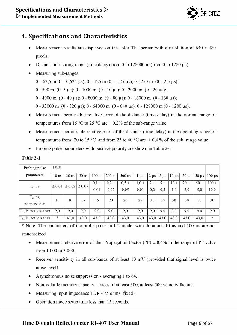
Probing pulse parameters with positive polarity are shown in Table 2-1.
Table 2-1
Probing pulse
parameters
Pulse
10 ns 20 ns 50 ns 100 ns 200 ns 500 ns 1 µs 2 µs 5 µs 10 µs 20 µs 50 µs 100 µs
τи, µs ≤ 0,01 ≤ 0,02 ≤ 0,05 0,1 ±
0,01
0,2 ±
0,02
0,5 ±
0,05
1,0 ±
0,01
2 ±
0,2
5 ±
0,5
10 ±
1,0
20 ±
2,0
50 ±
5,0
100 ±
10,0
Τн, ns,
no more than 10 10 15 15 20 20 25 30 30 30 30 30 30
U1, В, not less than 9,0 9,0 9,0 9,0 9,0 9,0 9,0 9,0 9,0 9,0 9,0 9,0 9,0
U2, В, not less than * 43,0 43,0 43,0 43,0 43,0 43,0 43,0 43,0 43,0 43,0 43,0 *
* Note: The parameters of the probe pulse in U2 mode, with durations 10 ns and 100 µs are not
standardized.
Measurement relative error of the Propagation Factor (PF) ± 0,4% in the range of PF value
from 1.000 to 3.000.
Receiver sensitivity in all sub-bands of at least 10 mV (provided that signal level is twice
noise level)
Asynchronous noise suppression - averaging 1 to 64.
Non-volatile memory capacity - traces of at least 300, at least 500 velocity factors.
Measuring input impedance TDR - 75 ohms (fixed).
Operation mode setup time less than 15 seconds.
Specifications and Characteristics Implemented Measurement Methods
Time Domain Reflectometer RI-407 User Manual Page 7 of 67
Continuous running RI-407 from the battery ACC1 at least 6 hours (or at least 10 hours from
the battery ACC2) and depends on the condition of the battery. Continuous running via AC
adapter is not limited.
Maximum electric power consumed by the RI-407 while charging the battery, not more than
40 W.
Overall dimensions of the RI-407 is not more than:
length - 363 mm
width - 295 mm
height - 170 mm
Weight of RI-407 with built-in battery no more than 3.5 kg
RI-407 is a compact device designed to work in indoor and outdoor conditions. RI-407 meets
climatic conditions Group 4 GOST 22261:
operating temperature range from -20 to 40 °C;
relative humidity 98%, at 25 °C;
transportation and storage conditions from -50 to 50 °C.
RI-407 is stable and resistant to the sinusoidal vibration in frequency range from 10 Hz to 55
Hz. RI-407 meets conditions Group 4 GOST 22261.
RI-407 is powered by the built-in Li-Ion battery (7,2 ± 0,7)V 7,0A. The design of the RI-407
provides control of battery discharge and automatic device shut down in 2, 4, 8, 32 or 64
minutes of idle time.
RI-407 does not emit toxic gases and audio noise.
Reliability:
MTBF - at least 6000 hours.
Service life - at least 5 years.
Delivery Contents Implemented Measurement Methods
Time Domain Reflectometer RI-407 User Manual Page 8 of 67
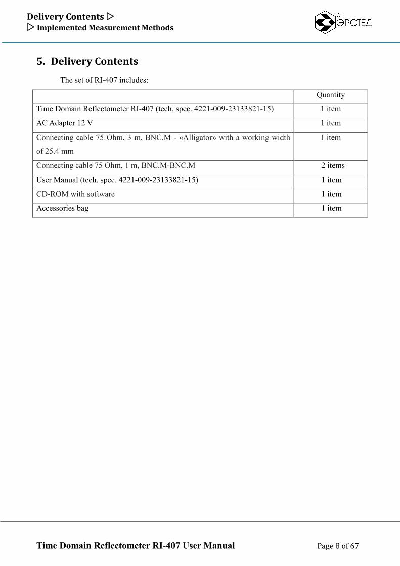
5. Delivery Contents
The set of RI-407 includes:
Quantity
Time Domain Reflectometer RI-407 (tech. spec. 4221-009-23133821-15) 1 item
AC Adapter 12 V 1 item
Connecting cable 75 Ohm, 3 m, BNC.M - «Alligator» with a working width
of 25.4 mm
1 item
Connecting cable 75 Ohm, 1 m, BNC.M-BNC.M 2 items
User Manual (tech. spec. 4221-009-23133821-15) 1 item
CD-ROM with software 1 item
Accessories bag 1 item
Design And Implemented Measurement Methods Implemented Measurement Methods
Time Domain Reflectometer RI-407 User Manual Page 9 of 67
6. Design And Implemented Measurement Methods
6.1. Implemented Measurement Methods
6.1.1. Time Domain Reflectometry (TDR) Method
The instrument uses a Time Domain Reflectometry method (TDR), which is based on the
phenomenon of a partial reflection of electromagnetic waves by the impedance irregularities in the
line. When applying the TDR method a rectangular probe pulse generated by the pulse generator is
sent into the line. Probe pulse propagating through the cable line, completely or partly reflected from
the fault area in the line (impedance irregularities) and returns to the receiver input. Reflection
waveform is observed on the screen and allows to determine the type of the fault (see Table 6-2) and
the distance to it. The reflected pulses are returned to the device after a certain time from the moment
of sending the probe pulse.
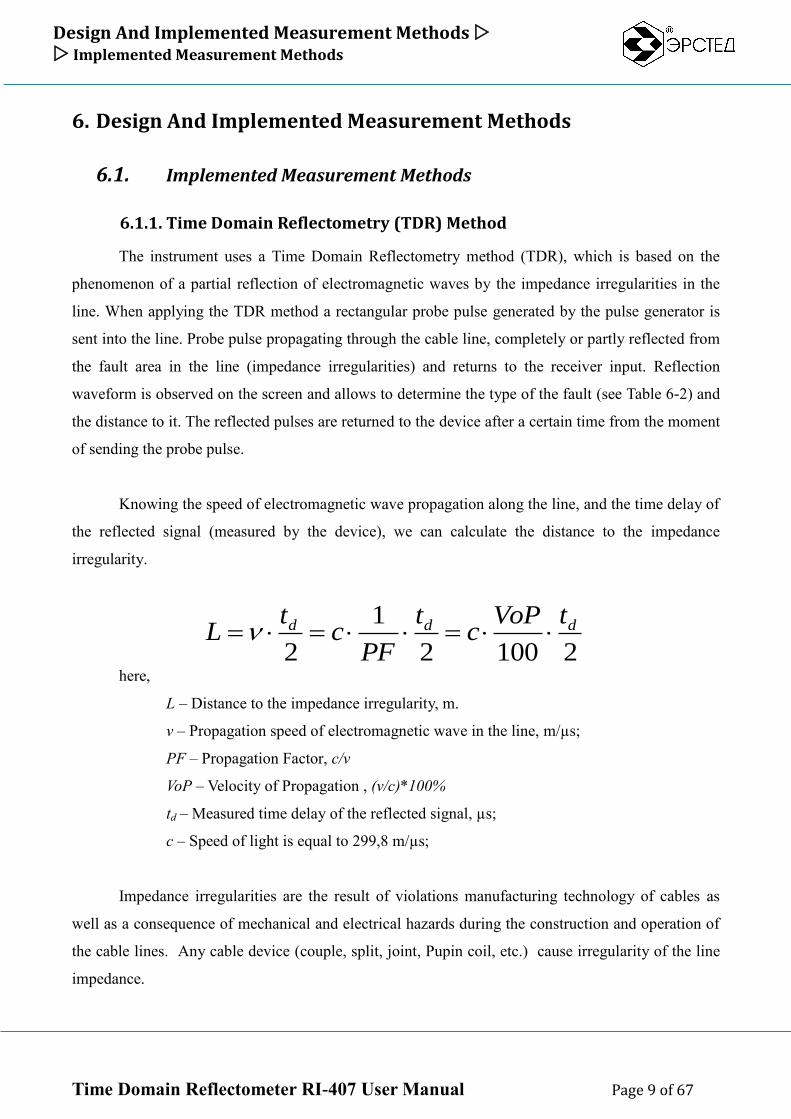
Knowing the speed of electromagnetic wave propagation along the line, and the time delay of
the reflected signal (measured by the device), we can calculate the distance to the impedance
irregularity.
here,
L – Distance to the impedance irregularity, m.
v – Propagation speed of electromagnetic wave in the line, m/µs;
PF – Propagation Factor, c/v
VoP – Velocity of Propagation , (v/c)*100%
td – Measured time delay of the reflected signal, µs;
с – Speed of light is equal to 299,8 m/µs;
Impedance irregularities are the result of violations manufacturing technology of cables as
well as a consequence of mechanical and electrical hazards during the construction and operation of
the cable lines. Any cable device (couple, split, joint, Pupin coil, etc.) cause irregularity of the line
impedance.
21002
1
2
ddd tVoPc
t
PFc
tL
Design And Implemented Measurement Methods Implemented Measurement Methods
Time Domain Reflectometer RI-407 User Manual Page 10 of 67
The impedance irregularities may be caused by any cable devices (couple, joint, Pupin coil,
etc.) or faults (open, short, partial open, partial shot, wetting core of the cable, leaks to the ground,
split pairs, etc.). TDR method allows to fix multiple irregularities both lumped and lengthy,
depending on the ratio of their length and the minimal wavelength of the spectrum of the probe
pulse.
The instrument generate a probe pulse with positive polarity amplitude is not less than 10V
(U1 mode), or not less than 45V (U2 mode) (see Table 4-1). The probe pulse width is automatically
adjusted according to the selected sub-range (see Table 6-1). Furthermore, pulse width can be set
manually by the user.
RI-407 automatically calculates the distance, according to the velocity factor and
measurement cursors positions on the screen. The distance measurement error is determined by the
sampling step of the instrument and by the velocity factor setting error.
Sampling step for each sub-range is set by default in such a way that the viewing window got
whole sub-range used by (see. Table 6-1). Sampling step can be adjusted (reduced or increased)
manually by the operator to minimize the instrumental error.
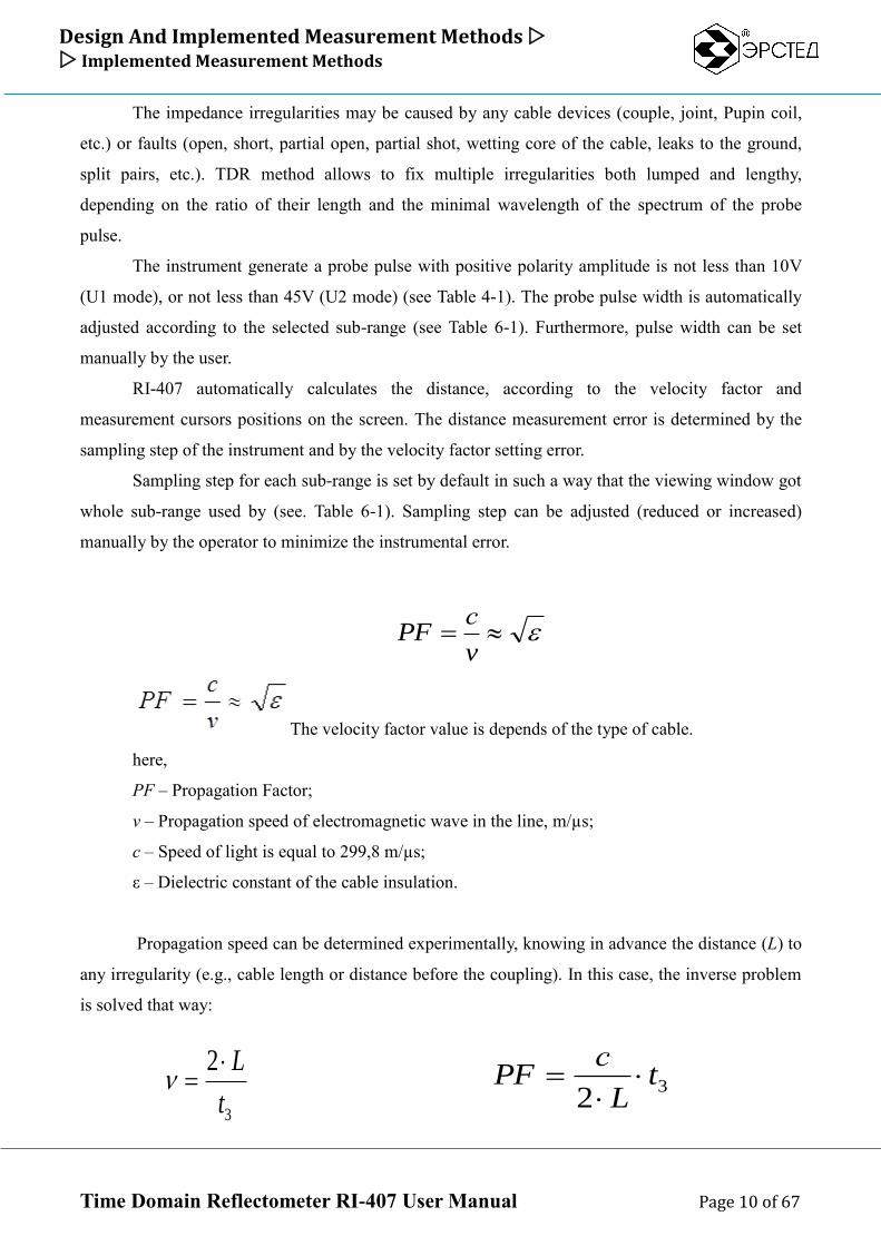
The velocity factor value is depends of the type of cable.
here,
PF – Propagation Factor;
v – Propagation speed of electromagnetic wave in the line, m/µs;
с – Speed of light is equal to 299,8 m/µs;
ε – Dielectric constant of the cable insulation.
Propagation speed can be determined experimentally, knowing in advance the distance (L) to
any irregularity (e.g., cable length or distance before the coupling). In this case, the inverse problem
is solved that way:
v
сPF
32
tL
сPF
3
2
t
L
Design And Implemented Measurement Methods Implemented Measurement Methods
Time Domain Reflectometer RI-407 User Manual Page 11 of 67
Additional errors are due to the distortion of the reflected signal in the lines with a frequency-
dependent losses. The measurement error affects the nature of irregularity, its value, the existence of
several irregularities in the line.
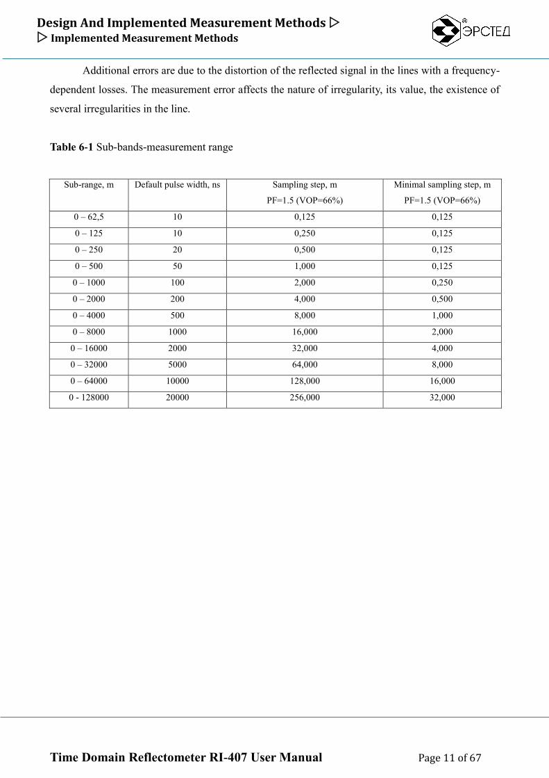
Table 6-1 Sub-bands-measurement range
Sub-range, m Default pulse width, ns Sampling step, m
PF=1.5 (VOP=66%)
Minimal sampling step, m
PF=1.5 (VOP=66%)
0 – 62,5 10 0,125 0,125
0 – 125 10 0,250 0,125
0 – 250 20 0,500 0,125
0 – 500 50 1,000 0,125
0 – 1000 100 2,000 0,250
0 – 2000 200 4,000 0,500
0 – 4000 500 8,000 1,000
0 – 8000 1000 16,000 2,000
0 – 16000 2000 32,000 4,000
0 – 32000 5000 64,000 8,000
0 – 64000 10000 128,000 16,000
0 - 128000 20000 256,000 32,000
Design And Implemented Measurement Methods Implemented Measurement Methods
Time Domain Reflectometer RI-407 User Manual Page 12 of 67
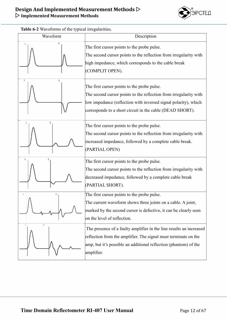
Table 6-2 Waveforms of the typical irregularities.
Waveform Description
The first cursor points to the probe pulse.
The second cursor points to the reflection from irregularity with
high impedance, which corresponds to the cable break
(COMPLIT OPEN).
The first cursor points to the probe pulse.
The second cursor points to the reflection from irregularity with
low impedance (reflection with inversed signal polarity), which
corresponds to a short circuit in the cable (DEAD SHORT).
The first cursor points to the probe pulse.
The second cursor points to the reflection from irregularity with
increased impedance, followed by a complete cable break.
(PARTIAL OPEN)
The first cursor points to the probe pulse.
The second cursor points to the reflection from irregularity with
decreased impedance, followed by a complete cable break
(PARTIAL SHORT).
The first cursor points to the probe pulse.
The current waveform shows three joints on a cable. A joint,
marked by the second cursor is defective, it can be clearly seen
on the level of reflection.
The presence of a faulty amplifier in the line results an increased
reflection from the amplifier. The signal must terminate on the
amp, but it’s possible an additional reflection (phantom) of the
amplifier.
Design And Implemented Measurement Methods Implemented Measurement Methods
Time Domain Reflectometer RI-407 User Manual Page 13 of 67
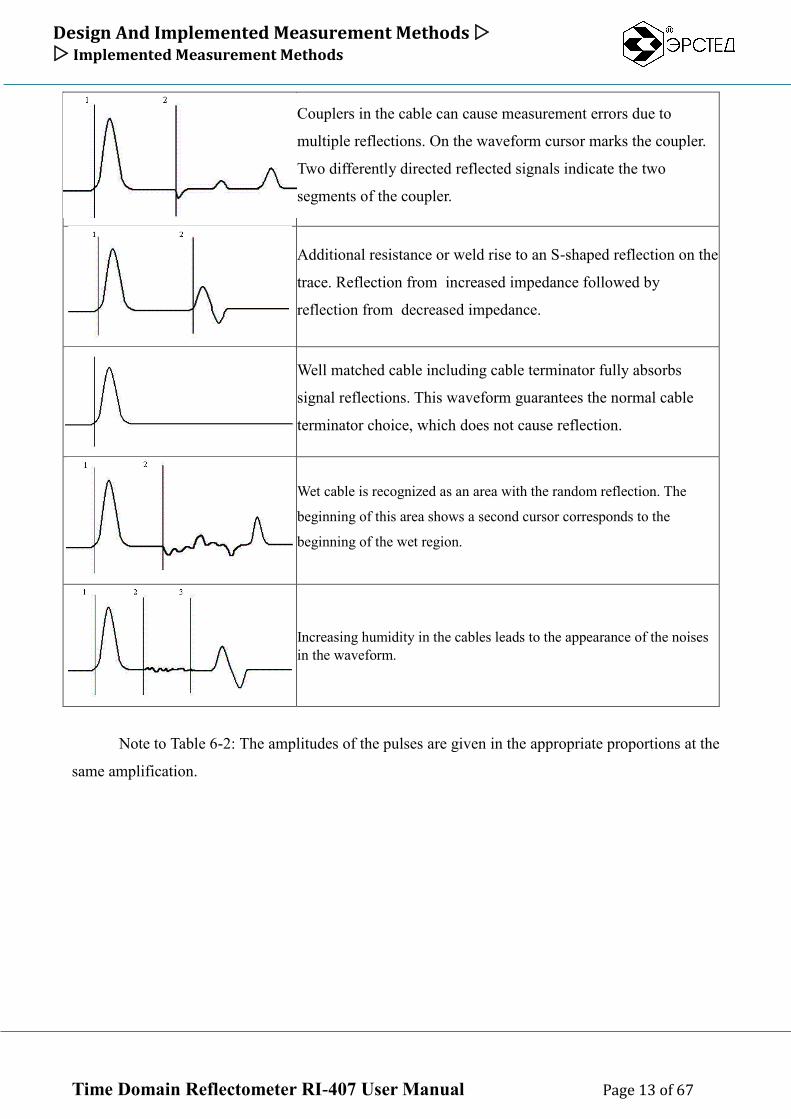
Couplers in the cable can cause measurement errors due to
multiple reflections. On the waveform cursor marks the coupler.
Two differently directed reflected signals indicate the two
segments of the coupler.
Additional resistance or weld rise to an S-shaped reflection on the
trace. Reflection from increased impedance followed by
reflection from decreased impedance.
Well matched cable including cable terminator fully absorbs
signal reflections. This waveform guarantees the normal cable
terminator choice, which does not cause reflection.
Wet cable is recognized as an area with the random reflection. The
beginning of this area shows a second cursor corresponds to the
beginning of the wet region.
Increasing humidity in the cables leads to the appearance of the noises
in the waveform.
Note to Table 6-2: The amplitudes of the pulses are given in the appropriate proportions at the
same amplification.
Design And Implemented Measurement Methods Implemented Measurement Methods
Time Domain Reflectometer RI-407 User Manual Page 14 of 67
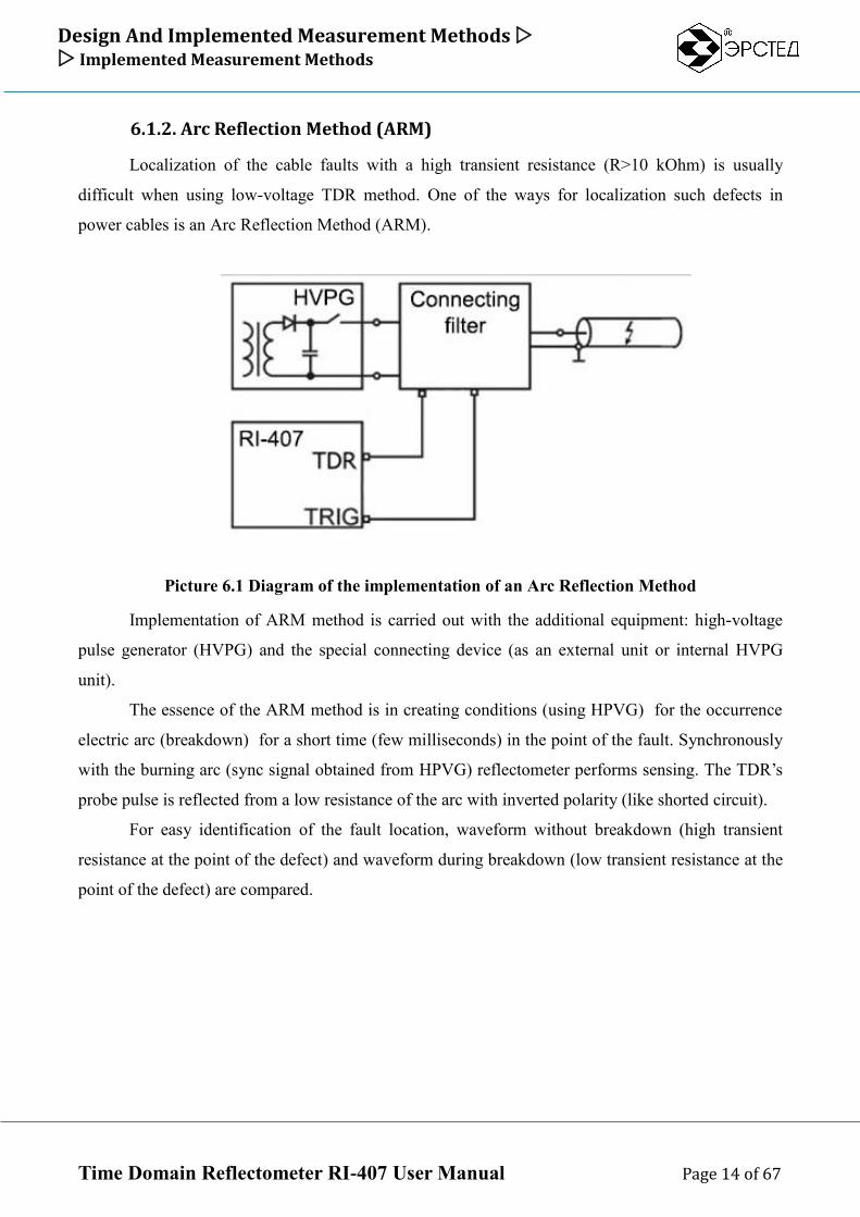
6.1.2. Arc Reflection Method (ARM)
Localization of the cable faults with a high transient resistance (R>10 kOhm) is usually
difficult when using low-voltage TDR method. One of the ways for localization such defects in
power cables is an Arc Reflection Method (ARM).
Picture 6.1 Diagram of the implementation of an Arc Reflection Method
Implementation of ARM method is carried out with the additional equipment: high-voltage
pulse generator (HVPG) and the special connecting device (as an external unit or internal HVPG
unit).
The essence of the ARM method is in creating conditions (using HPVG) for the occurrence
electric arc (breakdown) for a short time (few milliseconds) in the point of the fault. Synchronously
with the burning arc (sync signal obtained from HPVG) reflectometer performs sensing. The TDR’s
probe pulse is reflected from a low resistance of the arc with inverted polarity (like shorted circuit).
For easy identification of the fault location, waveform without breakdown (high transient
resistance at the point of the defect) and waveform during breakdown (low transient resistance at the
point of the defect) are compared.
Design And Implemented Measurement Methods Implemented Measurement Methods
Time Domain Reflectometer RI-407 User Manual Page 15 of 67
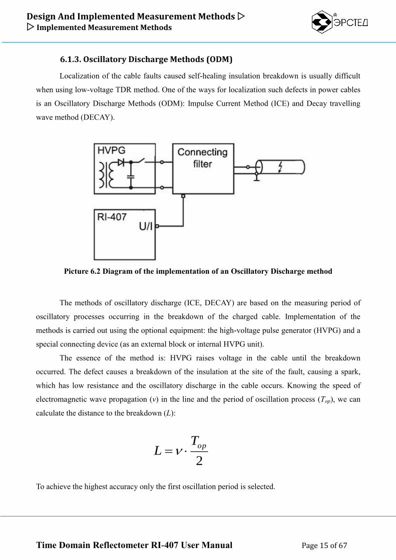
6.1.3. Oscillatory Discharge Methods (ODM)
Localization of the cable faults caused self-healing insulation breakdown is usually difficult
when using low-voltage TDR method. One of the ways for localization such defects in power cables
is an Oscillatory Discharge Methods (ODM): Impulse Current Method (ICE) and Decay travelling
wave method (DECAY).
Picture 6.2 Diagram of the implementation of an Oscillatory Discharge method
The methods of oscillatory discharge (ICE, DECAY) are based on the measuring period of
oscillatory processes occurring in the breakdown of the charged cable. Implementation of the
methods is carried out using the optional equipment: the high-voltage pulse generator (HVPG) and a
special connecting device (as an external block or internal HVPG unit).
The essence of the method is: HVPG raises voltage in the cable until the breakdown
occurred. The defect causes a breakdown of the insulation at the site of the fault, causing a spark,
which has low resistance and the oscillatory discharge in the cable occurs. Knowing the speed of
electromagnetic wave propagation (v) in the line and the period of oscillation process (Top), we can
calculate the distance to the breakdown (L):
To achieve the highest accuracy only the first oscillation period is selected.
2
opTL
Design And Implemented Measurement Methods Product View
Time Domain Reflectometer RI-407 User Manual Page 16 of 67
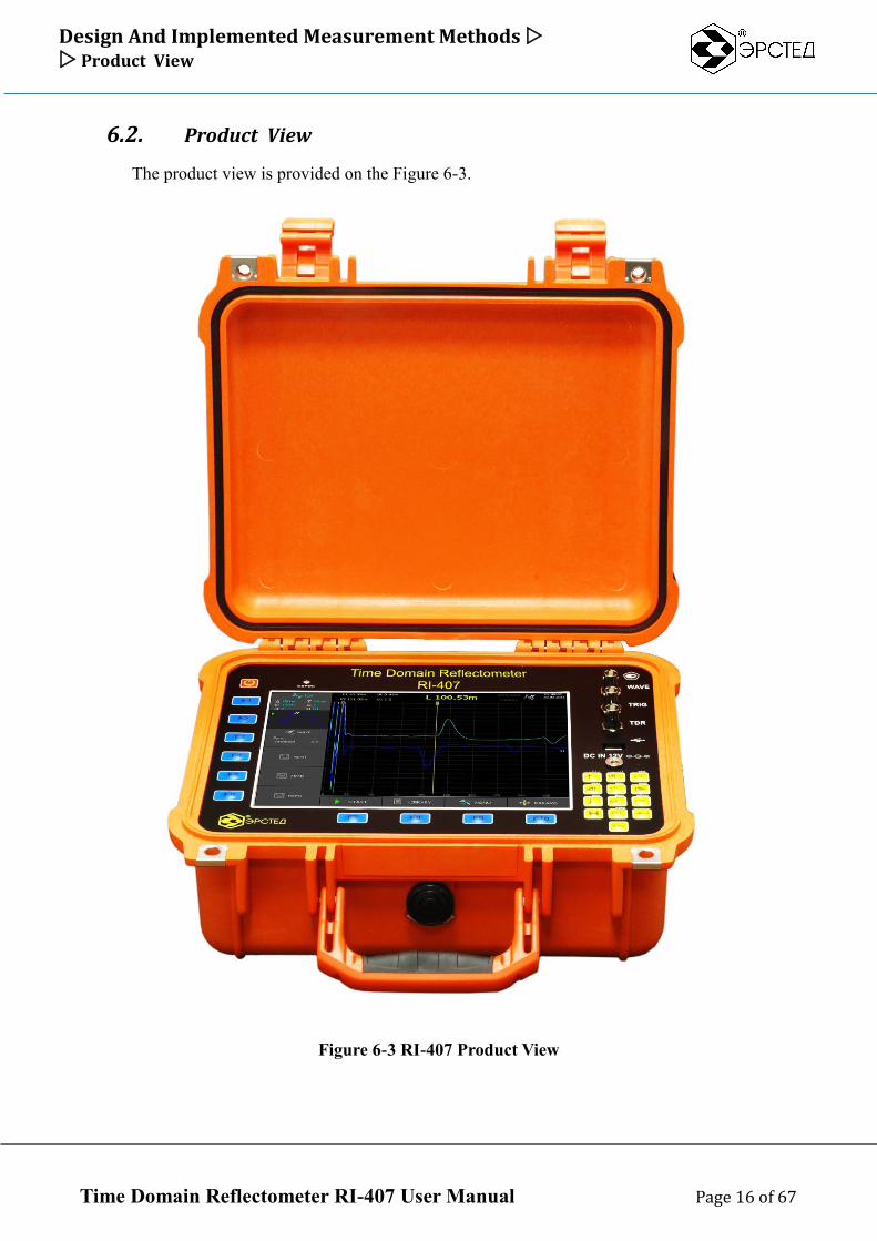
6.2. Product View
The product view is provided on the Figure 6-3.
Figure 6-3 RI-407 Product View
Design And Implemented Measurement Methods Interface Controls
Time Domain Reflectometer RI-407 User Manual Page 17 of 67
6.3. Interface Controls
6.3.1. Overview
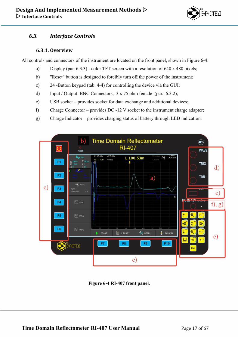
All controls and connectors of the instrument are located on the front panel, shown in Figure 6-4:
a) Display (par. 6.3.3) - color TFT screen with a resolution of 640 x 480 pixels;
b) "Reset" button is designed to forcibly turn off the power of the instrument;
c) 24 -Button keypad (tab. 4-4) for controlling the device via the GUI;
d) Input / Output BNC Connectors, 3 х 75 ohm female (par. 6.3.2);
e) USB socket – provides socket for data exchange and additional devices;
f) Charge Connector – provides DC -12 V socket to the instrument charge adapter;
g) Charge Indicator – provides charging status of battery through LED indication.
Figure 6-4 RI-407 front panel.
Design And Implemented Measurement Methods Interface Controls
Time Domain Reflectometer RI-407 User Manual Page 18 of 67
6.3.2 Connectors
All connectors of the instrument are located on the front panel:
TDR connector (input/output, 75 ohm, BNC female) - for connecting the instrument to the
cable either directly or through the appropriate HPVG socket (TDR socket on ADG-200);
TRIG connector (input, 75 ohm, BNC female) - for receiving Sync signal from the
appropriate HPVG output (TRIG socket on ADG-200), when using ARM method;
WAVE connector (input, 75 ohm, BNC female) - for receiving signal from the appropriate
HPVG output (WAVE socket on ADG-200), when using ODM methods (ICE, DECAY);
Charge Connector (DC 12 V) – provides connecting with external power supply for battery
charging;
Charge Indicator – provides charging status of the internal RI-407 battery through LED
indication;
USB-A connector to connect an external USB-flash drive for data exchange.
Design And Implemented Measurement Methods Interface Controls
Time Domain Reflectometer RI-407 User Manual Page 19 of 67
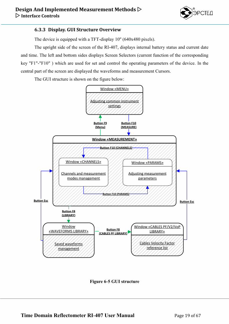
6.3.3 Display. GUI Structure Overview
The device is equipped with a TFT-display 10'' (640x480 pixels).
The upright side of the screen of the RI-407, displays internal battery status and current date
and time. The left and bottom sides displays Screen Selectors (current function of the corresponding
key "F1"-"F10" ) which are used for set and control the operating parameters of the device. In the
central part of the screen are displayed the waveforms and measurement Cursors.
The GUI structure is shown on the figure below:
Saved waveforms management
Window «WAVEFORMS LIBRARY»
Cables Velocity Factor reference list
Window «CABLES PF/V2/VoP LIBRARY»
Adjusting common instrument settings
Window «MENU»
Button F9(Menu)
Window «MEASUREMENT»
Channels and measurement modes management
Window «CHANNELS»
Adjusting measurement parameters
Window «PARAMS»
Button F10 (PARAMS)
Button F10 (CHANNELS)
Button F8 (CABLES PF LIBRARY)
Button F8(LIBRARY)
Button Esc Button Esc
Button F10(MEASURE)
Figure 6-5 GUI structure
Design And Implemented Measurement Methods Interface Controls
Time Domain Reflectometer RI-407 User Manual Page 20 of 67
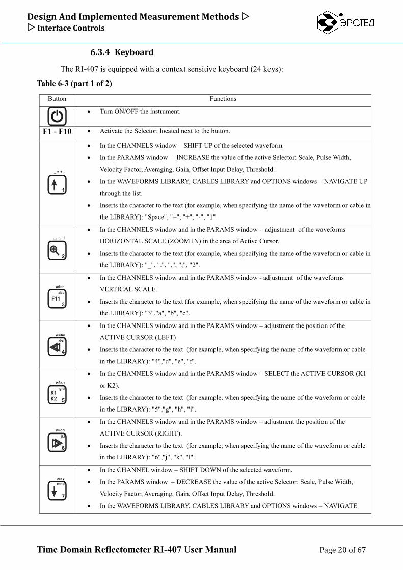
6.3.4 Keyboard
The RI-407 is equipped with a context sensitive keyboard (24 keys):
Table 6-3 (part 1 of 2)
Button Functions
Turn ON/OFF the instrument.
F1 - F10 Activate the Selector, located next to the button.
In the CHANNELS window – SHIFT UP of the selected waveform.
In the PARAMS window – INCREASE the value of the active Selector: Scale, Pulse Width,
Velocity Factor, Averaging, Gain, Offset Input Delay, Threshold.
In the WAVEFORMS LIBRARY, CABLES LIBRARY and OPTIONS windows – NAVIGATE UP
through the list.
Inserts the character to the text (for example, when specifying the name of the waveform or cable in
the LIBRARY): "Space", "=", "+", "-", "1".
In the CHANNELS window and in the PARAMS window - adjustment of the waveforms
HORIZONTAL SCALE (ZOOM IN) in the area of Active Cursor.
Inserts the character to the text (for example, when specifying the name of the waveform or cable in
the LIBRARY): "_", ".", ",", ";", "2".
In the CHANNELS window and in the PARAMS window - adjustment of the waveforms
VERTICAL SCALE.
Inserts the character to the text (for example, when specifying the name of the waveform or cable in
the LIBRARY): "3","a", "b", "c".
In the CHANNELS window and in the PARAMS window – adjustment the position of the
ACTIVE CURSOR (LEFT)
Inserts the character to the text (for example, when specifying the name of the waveform or cable
in the LIBRARY): "4","d", "e", "f".
In the CHANNELS window and in the PARAMS window – SELECT the ACTIVE CURSOR (K1
or K2).
Inserts the character to the text (for example, when specifying the name of the waveform or cable
in the LIBRARY): "5","g", "h", "i".
In the CHANNELS window and in the PARAMS window – adjustment the position of the
ACTIVE CURSOR (RIGHT).
Inserts the character to the text (for example, when specifying the name of the waveform or cable
in the LIBRARY): "6","j", "k", "l".
In the CHANNEL window – SHIFT DOWN of the selected waveform.
In the PARAMS window – DECREASE the value of the active Selector: Scale, Pulse Width,
Velocity Factor, Averaging, Gain, Offset Input Delay, Threshold.
In the WAVEFORMS LIBRARY, CABLES LIBRARY and OPTIONS windows – NAVIGATE
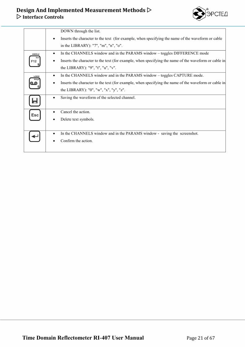
Design And Implemented Measurement Methods Interface Controls
Time Domain Reflectometer RI-407 User Manual Page 21 of 67
DOWN through the list.
Inserts the character to the text (for example, when specifying the name of the waveform or cable
in the LIBRARY): "7", "m", "n", "o".
In the CHANNELS window and in the PARAMS window – toggles DIFFERENCE mode
Inserts the character to the text (for example, when specifying the name of the waveform or cable in
the LIBRARY): "9", "t", "u", "v".
In the CHANNELS window and in the PARAMS window – toggles CAPTURE mode.
Inserts the character to the text (for example, when specifying the name of the waveform or cable in
the LIBRARY): "0", "w", "x", "y", "z".
Saving the waveform of the selected channel.
Cancel the action.
Delete text symbols.
In the CHANNELS window and in the PARAMS window - saving the screenshot.
Confirm the action.
Design And Implemented Measurement Methods GUI description
Time Domain Reflectometer RI-407 User Manual Page 22 of 67
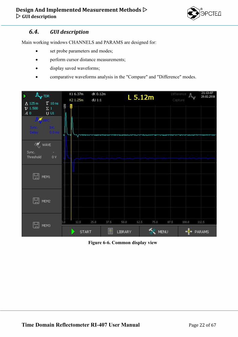
6.4. GUI description
Main working windows CHANNELS and PARAMS are designed for:
set probe parameters and modes;
perform cursor distance measurements;
display saved waveforms;
comparative waveforms analysis in the "Compare" and "Difference" modes.
Figure 6-6. Common display view
Design And Implemented Measurement Methods GUI description
Time Domain Reflectometer RI-407 User Manual Page 23 of 67
"CHANNELS" window is intended to control: activate/deactivate channels,
measurement method selection, position and scaling waveforms on the screen;
“PARAMS” window is intended to set the probing parameters;
In the central part of the display located a coordinate grid and waveform’s of the activated
channels (with appropriate color).
Vertical lines labeled 1 and 2 are measurement cursors ("K1" and "K2"). Measurement
cursors allow absolute and relative distance measurements on the waveform. Absolute distances to
the cursors "K1" and "K2" (from the origin) and relative distance «L» (between cursors) are
displayed on the dashboard of the grid.
On the dashboard are also displayed - the current cursor step «dK» (horizontal scaling), the
vertical scale «dU», mode "Difference" indicator, mode "Capture" indicator, “Probe” indicator (),
the current date and time, and the internal battery status.
Design And Implemented Measurement Methods GUI description
Time Domain Reflectometer RI-407 User Manual Page 24 of 67
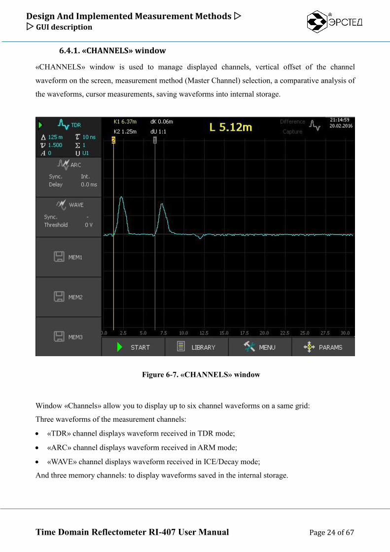
6.4.1. «CHANNELS» window
«CHANNELS» window is used to manage displayed channels, vertical offset of the channel
waveform on the screen, measurement method (Master Channel) selection, a comparative analysis of
the waveforms, cursor measurements, saving waveforms into internal storage.
Figure 6-7. «CHANNELS» window
Window «Channels» allow you to display up to six channel waveforms on a same grid:
Three waveforms of the measurement channels:
«TDR» channel displays waveform received in TDR mode;
«ARC» channel displays waveform received in ARM mode;
«WAVE» channel displays waveform received in ICE/Decay mode;
And three memory channels: to display waveforms saved in the internal storage.
Design And Implemented Measurement Methods GUI description
Time Domain Reflectometer RI-407 User Manual Page 25 of 67
To activate channel use channel selectors, displayed next to the buttons «F1» - «F6». Short
button pressure allows you to show or hide channel waveform. Long button pressure allows you to
select Master Channel (MC) and assigned measurement method (MC channel is labeled with symbol
in the channel selector).
Selecting MC switches instrument to the corresponding measurement mode:
«TDR» (button «F1») – switches instrument to the TDR mode;
«ARC» ( button «F2») – switches instrument to the ARM mode;
«WAVE» (button «F3») – switches instrument to the ODM (ICE/Decay) mode.
«MEM1», «MEM2», «MEM3» (buttons «F4»-«F6») – switches instrument to the TDR
mode;
With the selected MC channel the following actions are performed:
Editing measurement parameters of the MC (in the window «PARAMS»);
vertical waveform offset of the MC;
saving the waveform of the MC;
applying "Difference" view-mode relative to the MC;
For each activated channel waveform is displayed with the corresponding color. In the
channel selector are displayed instrument parameters that specific to the type (mode) of the channel:
For the TDR type channel – Scale (), probe Pulse Width (), Velocity of Propagation
(v), Averaging (), the Gain (A), Amplitude of the probe pulse (U);
For the ARM type channel – Synchronization source (Sync.) and Timeout for internal
synchronization (Delay);
For the WAVE type channel – threshold (Threshold).
At the bottom of the display above the buttons «F7» - «F10» the following selectors are
displayed:
"Start / Stop", button «F7» - starts / stops the measurement;
"LIBRARY", button «F8» - switch to "WAVEFORM LIBRARY"/"CABLES LIBRARY"
window, that provides access to the waveforms saved in the internal storage;
"MENU" button «F9» - switch to "MENU" window, provides access to the general instrument
settings and data exchange functions;
"PARAMS" button «F10» - switch to "PARAMS" window to configure the probe parameters.
Design And Implemented Measurement Methods GUI description
Time Domain Reflectometer RI-407 User Manual Page 26 of 67
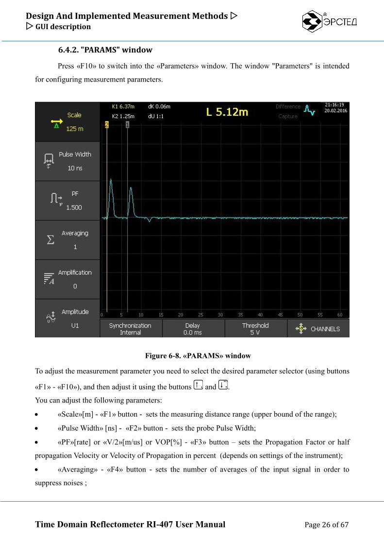
6.4.2. "PARAMS" window
Press «F10» to switch into the «Parameters» window. The window "Parameters" is intended
for configuring measurement parameters.
Figure 6-8. «PARAMS» window
To adjust the measurement parameter you need to select the desired parameter selector (using buttons
«F1» - «F10»), and then adjust it using the buttons and .
You can adjust the following parameters:
«Scale»[m] - «F1» button - sets the measuring distance range (upper bound of the range);
«Pulse Width» [ns] - «F2» button - sets the probe Pulse Width;
«PF»[rate] or «V/2»[m/us] or VOP[%] - «F3» button – sets the Propagation Factor or half
propagation Velocity or Velocity of Propagation in percent (depends on settings of the instrument);
«Averaging» - «F4» button - sets the number of averages of the input signal in order to
suppress noises ;
Design And Implemented Measurement Methods GUI description
Time Domain Reflectometer RI-407 User Manual Page 27 of 67
«Amplification» - «F5» button - sets the signal amplification;
«Amplitude» [V] - «F6» button - sets probe pulse Amplitude;
«Sync» - «F7» button - sets the source of the synchronization signal, specific parameter to
the ARM mode;
«Delay»[ms] - «F8» button - sets the delay of the data collection start, the specific parameter
to ARM mode;
«Threshold»[V] - «F9» button - sets the threshold signal level, specific parameter to the
ODM mode;
To switch instrument to the «CHANNELS» window press «F10»;
Design And Implemented Measurement Methods GUI description
Time Domain Reflectometer RI-407 User Manual Page 28 of 67
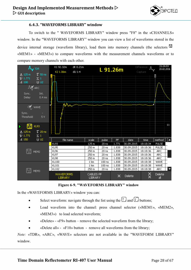
6.4.3. “WAVEFORMS LIBRARY” window
To switch to the " WAVEFORMS LIBRARY" window press "F8" in the «CHANNELS»
window. In the "WAVEFORMS LIBRARY” window you can view a list of waveforms stored in the
device internal storage (waveform library), load them into memory channels (the selectors
«MEM1» - «MEM3») to compare waveforms with the measurement channels waveforms or to
compare memory channels with each other.
Figure 6-9. "WAVEFORMS LIBRARY" window
In the «WAVEFORMS LIBRARY» window you can:
Select waveform: navigate through the list using the and buttons;
Load waveform into the channel: press channel selector («MEM1», «MEM2»,
«MEM3») to load selected waveform;
«Delete» - «F9» button – remove the selected waveform from the library;
«Delete all» - «F10» button - remove all waveforms from the library;
Note: «TDR», «ARC», «WAVE» selectors are not available in the "WAVEFORM LIBRARY"
window.
Design And Implemented Measurement Methods GUI description
Time Domain Reflectometer RI-407 User Manual Page 29 of 67
To switch instrument into the «CHANNELS» window press «Esc» button;
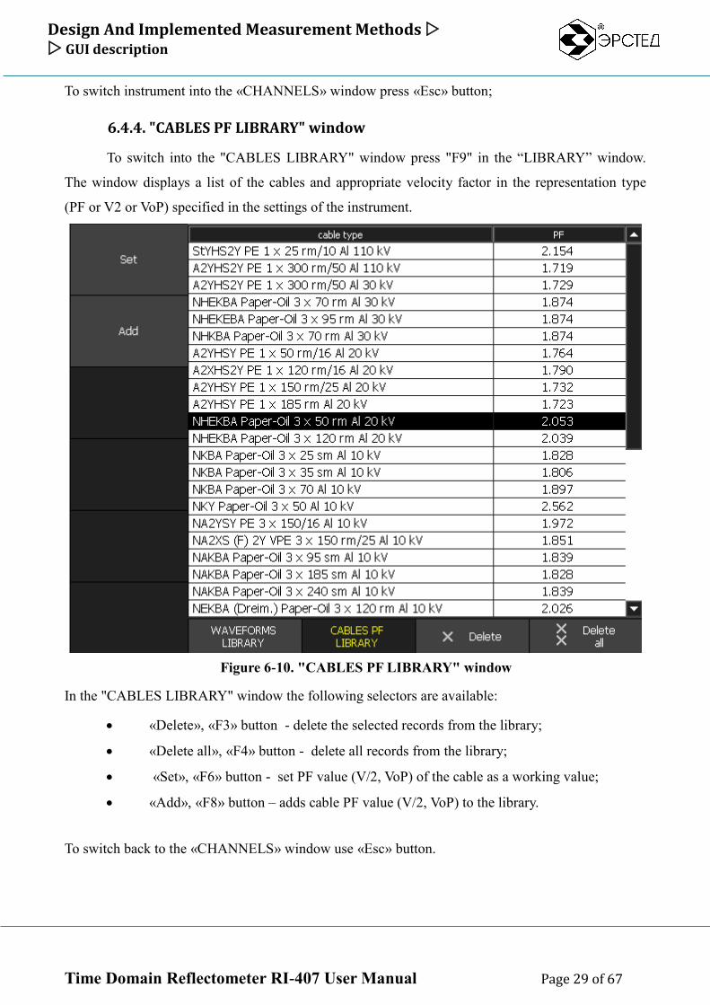
6.4.4. "CABLES PF LIBRARY" window
To switch into the "CABLES LIBRARY" window press "F9" in the “LIBRARY” window.
The window displays a list of the cables and appropriate velocity factor in the representation type
(PF or V2 or VoP) specified in the settings of the instrument.
Figure 6-10. "CABLES PF LIBRARY" window
In the "CABLES LIBRARY" window the following selectors are available:
«Delete», «F3» button - delete the selected records from the library;
«Delete all», «F4» button - delete all records from the library;
«Set», «F6» button - set PF value (V/2, VoP) of the cable as a working value;
«Add», «F8» button – adds cable PF value (V/2, VoP) to the library.
To switch back to the «CHANNELS» window use «Esc» button.
Design And Implemented Measurement Methods GUI description
Time Domain Reflectometer RI-407 User Manual Page 30 of 67
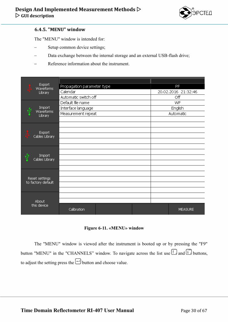
6.4.5. "MENU" window
The "MENU" window is intended for:
Setup common device settings;
Data exchange between the internal storage and an external USB-flash drive;
Reference information about the instrument.
Figure 6-11. «MENU» window
The "MENU" window is viewed after the instrument is booted up or by pressing the "F9"
button "MENU" in the "CHANNELS” window. To navigate across the list use and buttons,
to adjust the setting press the button and choose value.
Design And Implemented Measurement Methods GUI description
Time Domain Reflectometer RI-407 User Manual Page 31 of 67
In the "MENU" window the following selectors are available:
«Edit» - «F7» or button – switches to editing the selected setting;
«Reset to factory default» - «F5» button – reset to factory default settings and measurement
parameters;
«MEASUREMENT» - «F10» button – start to working with the instrument, switches into the
«CHANNELS» window;
«Export Waveforms Library» - «F1» button – export waveforms library into external storage
device such as USB-Flash;
«Import Waveforms Library» - «F2» button – import waveforms library from external
storage device such as USB-Flash;
«Export Cables Library» - «F3» button – export cable library into external storage device
such as USB-Flash;
«Import Cables Library» - «F4» button – import cable library from external storage device
such as USB-Flash;
«About this device» - «F6» button – information about the instrument software and hardware
version, serial number and the device manufacturer.
Safety Precautions GUI description
Time Domain Reflectometer RI-407 User Manual Page 32 of 67
7. Safety Precautions
To work with the RI-407 allowed only the experts who have studied the this User’s Guide.
RI-407 has no life-threatening voltages.
When the RI-407 simultaneously charges the battery via the charger is prohibited to open the
device.
When working on a cables lines experts should be required to comply with the safety
regulations for working on this type of lines.
Configuring and working with instrument Switching on the instrument
Time Domain Reflectometer RI-407 User Manual Page 33 of 67
8. Configuring and working with instrument
CAUTION: before connecting to the line, make sure there is no voltage on it.
PROHIBITED: to measure lines under voltage.
8.1. Switching on the instrument
To switch the RI-407 instrument on, press and hold the button for one second. After
about 15 seconds of booting process the device opens the common settings "MENU" window.
To switch into the operating measurement mode, press button «F10» («MEASUREMENT»).
The device opens the "CHANNELS" window and automatically loads to the measuring channels
configuration and parameters stored from the previous session.
Configuring and working with instrument Setting up common parameters of the RI-407
Time Domain Reflectometer RI-407 User Manual Page 34 of 67
8.2. Setting up common parameters of the RI-407
8.2.1. Option “Propagation Parameter Type”
The RI-407 instrument provides three options for displaying the speed of propagation of
electromagnetic waves in the cable line: as the propagation factor (PF=c/v), half velocity of
propagation (V/2, m/us) and velocity of propagation in percent of light speed (VoP=v/c*100 %).
To set the type of the velocity representation do following:
Open the "MENU” window;
Use and buttons to select the "Propagation parameter type" and press button;
In the dropdown list select the value you want using and buttons;
Press to confirm.
8.2.2. Option “Calendar” (date and time)
To set system date and time do following steps:
Open the "MENU” window (see 4.4.6);
Select “Calendar” from the list using and buttons and press ;
Select an option to edit using and buttons (day, month, year, hours, minutes,
seconds);
Use and buttons to increase or decrease a selected option;
Press .
8.2.3. Option “Automatic Switch Off” timeout
The RI-407 instrument provides the auto power off function in case of inactivity (no buttons
are pressed). All measurement settings and parameters are saved certainly.
To choose the Automatic Switch Off timeout do following:
Open the "MENU” window;
Select “Automatic switch off” from the list using and buttons and press ;
In the dropdown list select the value using and buttons; (off., 2 mins, 4 mins., 8
mins, 32 mins, 64 mins);
Press .
Configuring and working with instrument Setting up common parameters of the RI-407
Time Domain Reflectometer RI-407 User Manual Page 35 of 67
8.2.4. Option “Default waveform filename”
To define the default name for the saving waveforms do following:
Open the "MENU” window;
Select “Default file name” from the list using and buttons and press ;
o Use "F7" button to switch between languages;
o Use "F8" button to switch between symbols and numbers ("A B C" or "1 2 3");
To put a symbol - press the appropriate button on the keyboard (like on mobile phones);
To delete a symbol press ;
Press to finish.
8.2.5. Option “Interface language”
Open the "MENU” window;
Select “Interface language” from the list using and buttons and press ;
In the dropdown list select the language you want using and buttons;
Press to finish.
8.2.6. Reset instrument settings to factory values
Open the "MENU” window;
Press selector «Reset settings to factory default» (F5 button);
In the pop-up window "Reset default" to approve press ;
Reboot RI-407.
Note: waveforms and cabled libraries are not cleared when use this option.
Configuring and working with instrument Connecting the instrument to the testing cable
Time Domain Reflectometer RI-407 User Manual Page 36 of 67
8.3. Connecting the instrument to the testing cable
The following describes how to connect the instrument to operate in accordance with the chosen
measurement method
CAUTION: before connecting to the line, make sure there is no voltage on it.
PROHIBITED to measure lines under voltage.
8.3.1. TDR method: direct connection to the testing cable (without using
HVPG)
Direct connection provides the most detailed waveform of the cable under test. This connection is
effective for determining the cable infrastructure (couplings, joints, branches), cable length, and low-
resistance defects.
Connect the experimental line to the device directly via the "TDR" RI-407 socket, use the connection
cable supplied (when necessary);
8.3.2. ARM method: connection to the testing cable through HVPG
Connect the testing line to the high-voltage HVPG output (on the ADG200 sockets « » and «
»);
Low voltage signal BNC socket «TDR» of the RI-407 connect to a low voltage signal socket on
HVPG (on ADG-200 socket «TDR»);
Low voltage synchronization BNC input "TRIG" RI-407 connect to the synchronization output
of HVPG (on ADG-200 socket «TRIG»), use the connecting cable supplied (if necessary);
Select the measurement mode ARM on the HVPG (on ADG-200 turn switch «METHOD» to the
position «AR»);
Select the charging mode on HVPG:
(for ADG-200 it is available two cases:
o turn switch «MODE» to the position «MANUAL» - in this case the built-in HPVG
capacitor charging first, and then discharge it to the cable by the button «DISCHARGE
HV»)
o turn switch «MODE» to position «AUTO» - in this case HPVG charging testing cable
line directly, until the breakdown occurs);
)
Configuring and working with instrument Connecting the instrument to the testing cable
Time Domain Reflectometer RI-407 User Manual Page 37 of 67
8.3.3. ODM (ICE/Decay methods): connection to the testing cable through
HVPG
Connect the testing line to the high-voltage HVPG output (on the ADG200 sockets « » and
« »);
Signal input «WAVE» of the RI-407 connect to the appropriate (ICE/Decay) low voltage
signal jack on HVPG (on the ADG-200 this socket (ICE) named «WAVE»);
Select measuring method on HVPG (on ADG-200 handle «METHOD» in position
«WAVE»);
Select the charging mode on HVPG:
(for ADG-200 it is available two cases:
o turn switch «MODE» to the position «MANUAL» - in this case the built-in HPVG
capacitor charging first, and then discharge it to the cable by the button
«DISCHARGE HV»)
o turn switch «MODE» to position «AUTO» - in this case HPVG charging testing
cable line directly, until the breakdown occurs);
)
Configuring and working with instrument Setting measurement operating parameters
Time Domain Reflectometer RI-407 User Manual Page 38 of 67
8.4. Setting measurement operating parameters
8.4.1. Сhannels management
The term "channel" means the combination of the measurement parameters and waveform buffer.
The instrument RI-407 can simultaneously display six channels.
First three channels specialized for a specific measurement method :
«TDR» channel displays waveform received in TDR mode;
«ARC» channel displays waveform received in ARM mode;
«WAVE» channel displays waveform received in ICE/Decay mode;
And next three channels are memory channels that intended to display waveforms saved in the
internal storage.
To define the set of channels to display, do following:
open «CHANNELS» window;
activate / deactivate the desired channels by shortly pressing the buttons «F1»- «F6»
8.4.2. "Master Channel"(MC) term definition . MC selection.
By the term "Master Channel" (MC) means one of the channels that specifying the instrument
current measurement mode, waveform buffer for the data coming from the assigned measurement
input, and the set of probing parameters. Other channels are synchronize their waveform scale
according the MC.
All parameters adjustments in the window “PARAMS” are performed for the MC.
Also, for the MC the following operations are performed:
Arrange the waveform vertical offset in the “CHANNELS” window;
Saving сurrent waveform to the waveform library;
Defines reference waveform for the "Difference" view mode.
Any of the six channels can be selected as the MC channel. To select the MC do following:
Open «CHANNELS» window;
Long press (with delay about 1 sec.) to the appropriate channel button allows you to select
the "Master Channel" (indicated by an icon in the channel selector).
Configuring and working with instrument Setting measurement operating parameters
Time Domain Reflectometer RI-407 User Manual Page 39 of 67
8.4.3. Selection Measurement Method (Mode)
Setting operating parameters of RI-407 should be started with selection of the Measurement
Method. Measurement Method defined by selected "Master Channel" - one of a specialized
(customized for a specific measurement method) measurement channels.
To select Measurement Method:
Open «CHANNELS» window;
Long button to select method (mode):
o «F1» selector «TDR» - to operating in TDR mode;
o «F2» selector «ARC» - to operating in ARM mode;
o «F3» selector «WAVE» - to operating in WAVE mode (ICE/Decay);
"Master Channel" is indicated by an icon in the channel selector.
8.4.4. Adjusting measurement Scale (sub-range)
To set measurement Scale (sub-range) do following:
Open «PARAMS» window;
Press "F1" to choose selector "Scale";
Use and buttons to select a value;
The parameter is applied to the following measurement methods: TDR, ARM, WAVE (ICE/Decay).
8.4.5. Adjusting probe Pulse Width
To set the probe Pulse Width:
Open «PARAMS» window;
Press "F2" to choose selector "Pulse Width";
Use and buttons to adjust value: 10 ns, 20 ns, 50 ns, 100 ns, 200 ns, 500 ns, 1
µs, 2 µs, 5 µs, 10 µs, 20 µs, 50 µs, 100 µs.
This parameter is applied to the following measurement methods: TDR, ARM.
In the WAVE mode this parameter is ignored.
8.4.6. Adjusting Velocity Factor value (PF, v/2, VoP)
To set the Velocity Factor:
Open «PARAMS» window;
Press "F3" to choose "PF" selector (or “V/2”, “VoP” selectors depending on common
settings of the instrument);
Configuring and working with instrument Setting measurement operating parameters
Time Domain Reflectometer RI-407 User Manual Page 40 of 67
Use and buttons to adjust value;
NOTE: Setting the Velocity Factor from the Cable Library is described in p. 8.8.2.
This parameter is applied to the following measurement methods: TDR, ARM, WAVE (ICE/Decay).
8.4.7. Adjusting Averaging value
To set the Averaging to suppress asynchronous noise:
Open «PARAMS» window;
Press "F4" to choose "Averaging" selector;
Use and buttons to adjust value: from 1 (no noise suppression) to 64 (max
noise suppression);
This parameter is applied to the measurement methods: TDR, ARM. In the WAVE mode this
parameter is ignored.
8.4.8. Adjusting Amplification value
To set Amplification value do following:
Open «PARAMS» window;
Press "F5" to choose "Amplification" selector;
Use and buttons to adjust value from 0 to 255.
This parameter is applied to the following measurement methods: TDR, ARM, WAVE (ICE/Decay).
8.4.9. Adjusting Amplitude of the probe pulse
To set the Amplitude of the probe pulse:
Open «PARAMS» window;
Press "F6" to choose "Amplitude" selector;
Use and buttons to adjust value: U1(about 10V on match load) or U2 (about
90V on match load);
This parameter is applied to the measurement modes: TDR, ARM. In the WAVE mode this parameter
is ignored.
8.4.10. Selection Synchronization Source for ARM mode
For the ARM mode Synchrosignal (that an arc is just burned) to start low voltage TDR
probing may be got from two sources:
Configuring and working with instrument Setting measurement operating parameters
Time Domain Reflectometer RI-407 User Manual Page 41 of 67
External source: using signal supplied to the synchronization input (TRIG) of the
instrument;
Internal source: using signal supplied to the measuring input (TDR) with adjusted
delay;
To set the Synchronization Source:
Open «PARAMS» window;
Press "F7" to choose «Synchronization» selector;
Use and buttons to select a value "Internal" (measuring input TDR signal
synchronization) or "external" (TRIG input signal synchronization).
This parameter is applied to the measurement mode ARM. In the TDR, WAVE modes this parameter
is ignored.
8.4.11. Adjusting time Delay for ARM mode
When measuring using ARM method it’s allowed to set the delay between the
synchronization signal and the start of the measurement (low voltage TDR probing). Delay allows
you to choose an optimal moment of the arc burning to get good reflection.
To set a delay do following:
Open «PARAMS» window;
Press "F8" to choose "Delay" selector;
Use and buttons to adjust value from 0 to 50 ms, step 0.2 ms.
This parameter is applied to the measurement mode ARM with internal synchronization. In the TDR,
WAVE modes this parameter is ignored.
8.4.12. Adjusting trigger Threshold for ODM mode (WAVE input)
When measuring using Oscillatory Discharge Method (ODM), you can set trigger Threshold
to start recording of the oscillatory discharge process. Thus, when the level of signal from WAVE
input reaches Threshold instrument starts recording Oscillatory Discharge process.
To set the trigger Threshold:
Open «PARAMETERS» window
Press "F9 to activate "Threshold" selector;
Use and buttons to select a numeric value from -165 to 165 V, with step 5 V.
The parameter is applied to the Oscillatory Discharge «WAVE» mode. In the TDR, ARM modes this
parameter is ignored.
Configuring and working with instrument Setting measurement operating parameters
Time Domain Reflectometer RI-407 User Manual Page 42 of 67
8.4.13. Adjusting the input impedance
In the RI-407 impedance of the measuring input «TDR» is fixed - 75 ohms. Adjusting the
input impedance of the instrument is not required.
8.4.14. Adjusting vertical waveform position
For clear viewing on the screen several signals simultaneously the instrument allow to adjusting
vertical position of each channel waveform. To set the vertical position of the channel waveform:
Open «CHANNELS» window;
Select required channel as the "Master Channel" by press and hold the button (F1…F6) of
appropriate channel selector. Selector "Master Channel" is marked with «».
Adjust vertical position of the waveform using and buttons.
8.4.15. Adjusting Horizontal Zooming
To adjust the horizontal Zoom around any point on the waveform:
Open «CHANNELS» or «PARAMS» window;
Select measurement cursor by pressing "К1" or "К2";
Use and buttons for positioning selected cursor to the required point on the waveform;
Press for Zoom In (more detalization) or for Zoom Out (less detalization);
Control cursor step - “dK” at the top of the screen, max cursor step is 256 m, min - 0.01 m.
8.4.16. Adjusting Vertical Scaling
To adjust vertical scaling:
Open «CHANNELS» or «PARAMS» window;
repeatedly press «F11» to choose the most convenient dU scale: 1:1, 1:2, 1:4. The current
value of dU is displayed at the top of the screen.
8.4.17. “Difference” mode switch on/off
The device has a special pointwise subtraction mode designed to suppress noise and waveforms
differences analysis. To set the "difference" is necessary:
Open «CHANNELS» window;
As the "Master Channel" select (press and hold the channel selector button) one of the six
channels to adjust the pointwise subtraction. Selector "master channel" is marked with «».
Press "F12", wherein the "Difference" mode indicator is activated at the top of the screen;
Configuring and working with instrument Setting measurement operating parameters
Time Domain Reflectometer RI-407 User Manual Page 43 of 67
On the screen you will see the same waveform of the "Master Channel", and the pointwise
subtraction(relative to MC) result waveforms of the other activated channels;
To switch off “Difference” mode press "F12".
8.4.18. “Capture” mode switch on/off
The device has a special capture mode of fixing all the waveform changes on the screen for
an arbitrary time interval intended to identify "flickering" defects (time unstable). To set the
"Capture" mode:
Open «CHANNELS» or «PARAMS» window;
Press «F13» and control “Capture” mode indication at the top of the screen;
To switch off this mode press any key (except , , and ).
Configuring and working with instrument Operating procedure
Time Domain Reflectometer RI-407 User Manual Page 44 of 67
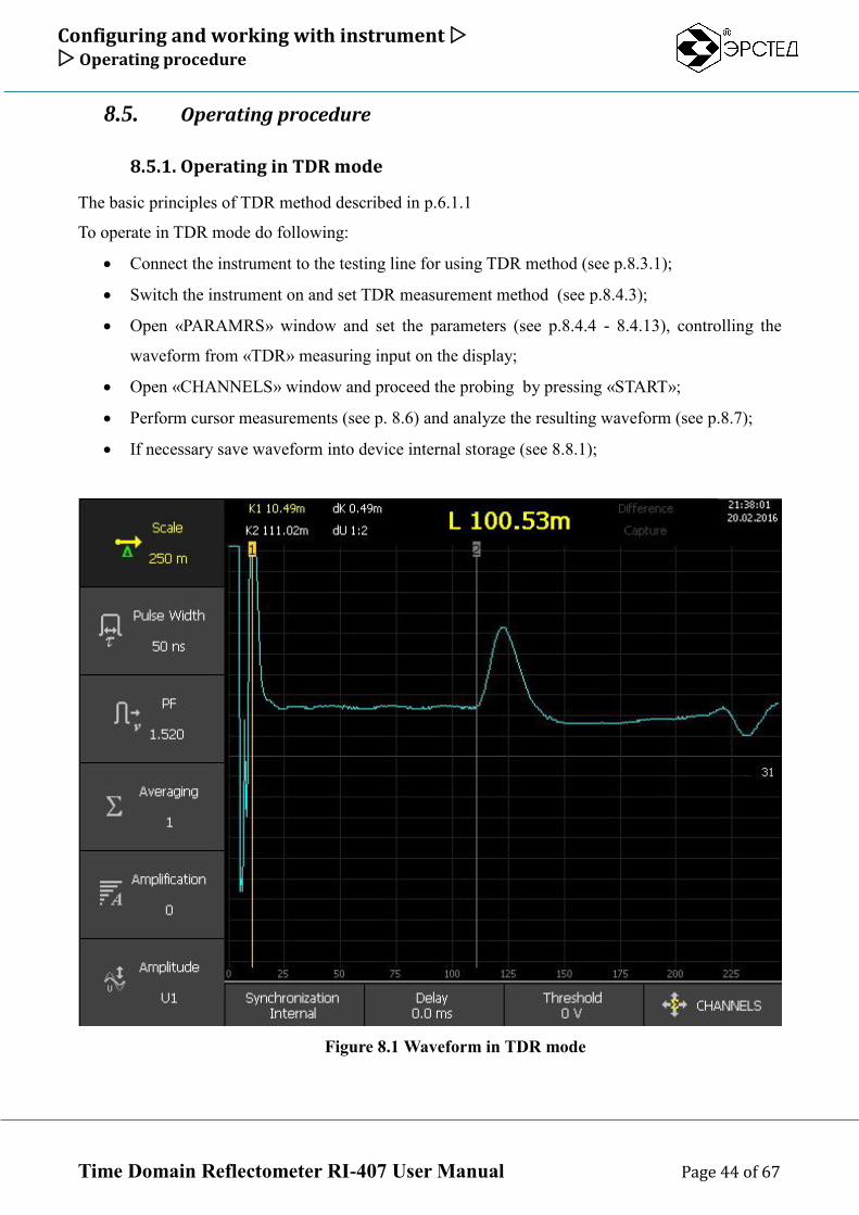
8.5. Operating procedure
8.5.1. Operating in TDR mode
The basic principles of TDR method described in p.6.1.1
To operate in TDR mode do following:
Connect the instrument to the testing line for using TDR method (see p.8.3.1);
Switch the instrument on and set TDR measurement method (see p.8.4.3);
Open «PARAMRS» window and set the parameters (see p.8.4.4 - 8.4.13), controlling the
waveform from «TDR» measuring input on the display;
Open «CHANNELS» window and proceed the probing by pressing «START»;
Perform cursor measurements (see p. 8.6) and analyze the resulting waveform (see p.8.7);
If necessary save waveform into device internal storage (see 8.8.1);
Figure 8.1 Waveform in TDR mode
Configuring and working with instrument Operating procedure
Time Domain Reflectometer RI-407 User Manual Page 45 of 67
8.5.2. Operating in ARM mode
The basic principles of the ARM method described in p. 8.3.2
To operate in ARM mode do following:
Connect the device to the test line for using ARM method (see 8.3.2);
Switch the instrument on and select ARM mode (see 8.4.3);
Open «PARAMS» window and adjust the parameters (see p.8.4.4 - 8.4.13), controlling the
waveform from «TDR» measuring input on the display;
Open «CHANNELS» window and proceed the probing by pressing «START»;
If necessary save waveform before breakdown fired into the device internal storage (see
8.8.1);
With activated «TDR» channel (with a just received waveform), switch the device to the
ARM mode - «ARC» (see 8.4.3);
The instrument switches to standby mode waiting for the HVPG-arc synchronization signal
(breakdown) (from TRIG or TDR input. see 8.3.2);
Using HVPG fire a cable breakdown;
At the moment of ignition of the electric arc HVPG synchronization signal will start RI-407
probing once, the resulting ARM waveform (reflected from the arc at the point of the
breakdown) displayed in the AR channel;
Perform cursor measurements and analyze the resulting waveform. In point of the breakdown
waveform will look like typical short circuit (see. 6.7.2).
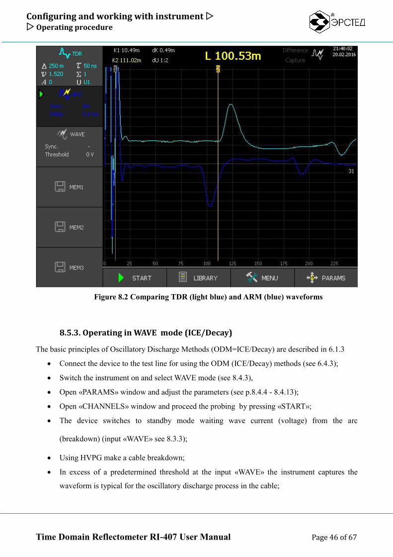
Compare waveforms "before the breakdown" and "at the time of the breakdown”
If necessary save ARM waveform into device internal storage (see 8.8.1);
Configuring and working with instrument Operating procedure
Time Domain Reflectometer RI-407 User Manual Page 46 of 67
Figure 8.2 Comparing TDR (light blue) and ARM (blue) waveforms
8.5.3. Operating in WAVE mode (ICE/Decay)
The basic principles of Oscillatory Discharge Methods (ODM=ICE/Decay) are described in 6.1.3
Connect the device to the test line for using the ODM (ICE/Decay) methods (see 6.4.3);
Switch the instrument on and select WAVE mode (see 8.4.3),
Open «PARAMS» window and adjust the parameters (see p.8.4.4 - 8.4.13);
Open «CHANNELS» window and proceed the probing by pressing «START»;
The device switches to standby mode waiting wave current (voltage) from the arc
(breakdown) (input «WAVE» see 8.3.3);
Using HVPG make a cable breakdown;
In excess of a predetermined threshold at the input «WAVE» the instrument captures the
waveform is typical for the oscillatory discharge process in the cable;
Configuring and working with instrument Operating procedure
Time Domain Reflectometer RI-407 User Manual Page 47 of 67
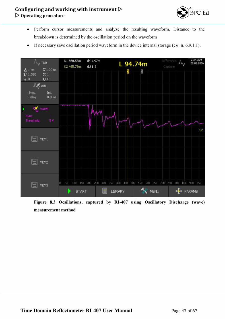
Perform cursor measurements and analyze the resulting waveform. Distance to the
breakdown is determined by the oscillation period on the waveform
If necessary save oscillation period waveform in the device internal storage (см. п. 6.9.1.1);
Figure 8.3 Ocsillations, captured by RI-407 using Oscillatory Discharge (wave)
measurement method
Configuring and working with instrument Cursor measurements
Time Domain Reflectometer RI-407 User Manual Page 48 of 67
8.6. Cursor measurements
8.6.1. Measuring the distance to the fault (heterogeneity) of the cable
To measure the distance to the heterogeneity:
Perform cable line probing (see 8.5)
Use the button to activate cursor "К1" or "К2";
Use and buttons to set the cursor position at the beginning of heterogeneity area;
Determine the distance numeric value "К1" ("К2") at the top of the screen;
ATTENTION. For the correct interpretation of results, it is necessary to establish the velocity factor
corresponding to the type of cable measured line.
ATTENTION. Connecting the measured line to the device with connecting cables, take into account
their length when determining distance values.
ATTENTION. The most accurate cursor positioning in the heterogeneity response area is achieved
adjusting zoom (see. p. 8.4.15).
8.6.2. Measuring Velocity Factor(PF, v2, VoP) knowing in advance the length
of the cable
You can measure Velocity Factor value if you know in advance the length of some cable section (for
ex. the entire length of the cable, distance to known joint etc.)
To measure velocity factor do following:
Perform cable test in TDR mode (see 8.5.1)
Use the button to activate cursor "К1";
Use and buttons to set the first cursor to the front of reflected signal from the
start of the section;
Use the button to activate cursor "К2";
Use and buttons to set the second cursor to the front of reflected signal from
end of the section;
Without moving the cursors adjust Velocity Factor value (see 8.4.6), achieving
equality distance L=|K1-K2| to the known length of the measured cable section.
ATTENTION. Connecting the measured line to the device by connecting cables, take into account
their length when determining distance values.
Configuring and working with instrument Cursor measurements
Time Domain Reflectometer RI-407 User Manual Page 49 of 67
8.6.3. Measuring distance between heterogeneities of the cable line
To measure the distance between heterogeneities of the cable line:
Perform cable TDR test (see 8.5.1)
Use the button to activate cursor "К1";
Use and buttons to set the cursor position at the beginning of the first heterogeneity
front;
Use the button to activate cursor "К2";
Use and buttons to set the cursor position at the beginning of the second heterogeneity
front;
Determine the distance numerical value next to "L =" in the upper part of the screen just
above the grid.
Configuring and working with instrument Analysis of typical heterogeneities of the cable line
Time Domain Reflectometer RI-407 User Manual Page 50 of 67
8.7. Analysis of typical heterogeneities of the cable line
Notes to Figure 8-4 - 8-7: in the top of figures the test line is schematically shown in the
lower part - the waveform of the line.
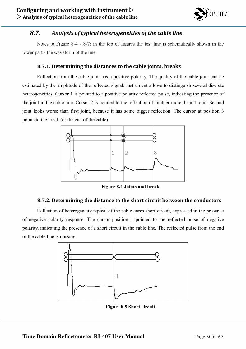
8.7.1. Determining the distances to the cable joints, breaks
Reflection from the cable joint has a positive polarity. The quality of the cable joint can be
estimated by the amplitude of the reflected signal. Instrument allows to distinguish several discrete
heterogeneities. Cursor 1 is pointed to a positive polarity reflected pulse, indicating the presence of
the joint in the cable line. Cursor 2 is pointed to the reflection of another more distant joint. Second
joint looks worse than first joint, because it has some bigger reflection. The cursor at position 3
points to the break (or the end of the cable).
Figure 8.4 Joints and break
8.7.2. Determining the distance to the short circuit between the conductors
Reflection of heterogeneity typical of the cable cores short-circuit, expressed in the presence
of negative polarity response. The cursor position 1 pointed to the reflected pulse of negative
polarity, indicating the presence of a short circuit in the cable line. The reflected pulse from the end
of the cable line is missing.
Figure 8.5 Short circuit
Configuring and working with instrument Analysis of typical heterogeneities of the cable line
Time Domain Reflectometer RI-407 User Manual Page 51 of 67
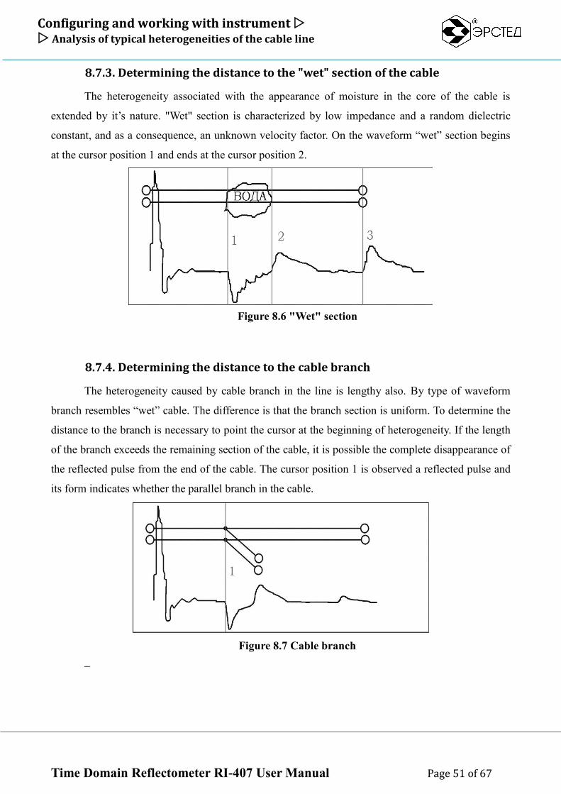
8.7.3. Determining the distance to the "wet" section of the cable
The heterogeneity associated with the appearance of moisture in the core of the cable is
extended by it’s nature. "Wet" section is characterized by low impedance and a random dielectric
constant, and as a consequence, an unknown velocity factor. On the waveform “wet” section begins
at the cursor position 1 and ends at the cursor position 2.
Figure 8.6 "Wet" section
8.7.4. Determining the distance to the cable branch
The heterogeneity caused by cable branch in the line is lengthy also. By type of waveform
branch resembles “wet” cable. The difference is that the branch section is uniform. To determine the
distance to the branch is necessary to point the cursor at the beginning of heterogeneity. If the length
of the branch exceeds the remaining section of the cable, it is possible the complete disappearance of
the reflected pulse from the end of the cable. The cursor position 1 is observed a reflected pulse and
its form indicates whether the parallel branch in the cable.
Figure 8.7 Cable branch
Configuring and working with instrument Working with Waveform Library
Time Domain Reflectometer RI-407 User Manual Page 52 of 67
8.8. Working with Waveform Library
8.8.1. Saving waveform to the Waveform Library
To save waveform to the library:
Perform cable line test (see 8.5);
As a master channel select the channel with waveform you want to save (see 8.4.2);
press and in the pop-up window: "Save the waveform of channel x?" press button to
confirm or “Esc” to cancel;
The device automatically opens the window "WAVEFORMS LIBRARY" (see 6.4.3);
Specify a name for the waveform (or leave the default name);
Finnaly, press the button ;
Close the window "WAVEFORMS LIBRARY" by pressing “Esc”.
ATTENTION. The device automatically saves the probing parameters used to get the waveform.
8.8.2. Loading waveform from the Waveform Library
The instrument lets you load and display up to three waveforms to a specialized memory
channels (channels «MEM1» - «MEM3»). It is possible to simultaneously work with the data
coming from the measuring inputs. To load the waveform from the library to the memory channel:
Open the window "WAVEFORMS LIBRARY"
Use and buttons to select the appropriate waveform from the library;
By pressing any of "F4" – "F6" load the waveform from the library to the display channel;
Close the window "WAVEFORMS LIBRARY" by pressing “Esc”
8.8.3. Delete waveform from the Waveform Library
To delete waveform from the library:
Open the window "WAVEFORMS LIBRARY";
Use and buttons to select the appropriate waveform from the library;
Press "F9" opposite "Delete" selector;
In the pop-up window: "Delete the selected waveform from the memory?" - Confirm the
action by pressing the button ;
Configuring and working with instrument Working with Waveform Library
Time Domain Reflectometer RI-407 User Manual Page 53 of 67
8.8.4. Clear Waveform Library
To clear library:
Open the window "WAVEFORMS LIBRARY";
Press "F5" opposite "Delete all" selector;
In the pop-up window: "Delete all waveforms from the memory?" - Confirm the action by
pressing the button or press “Esc” to cancel;
To close window "WAVEFORMS LIBRARY" press “Esc”
8.8.5. Export waveform library to USB-Flash
To export waveform library to the USB-Flash:
Open the window "MENU";
Insert USB-Flash into the USB-port;
Wait until the device identifies the USB-Flash (flashing USB-Flash LED);
Press "F1" opposite "Export waveforms library”;
At the end of the copying window pops up: "Waveforms library successfully exported to a
folder (the path to the folder)" - confirm the action by pressing the button .
8.8.6. Import waveform library from USB-Flash
To import waveform library from USB-Flash into the device internal storage:
Open the window "MENU";
Insert USB-Flash into the USB-port;
Wait until the device identifies the USB-Flash (flashing USB-Flash LED);
Press "F2" opposite "Import waveforms library”;
Use and buttons to select the folder;
Press , a window pops up: "You're going to import the library to replace the current one.
Do you want to export the current library?" – Press button , to backup current library into
an external drive before replacing. Press to proceed action without backup;
After copying window pops-up: " WAVEFORMS LIBRARY successfully imported" -
confirm the action by pressing the button
Configuring and working with instrument Working with Waveform Library
Time Domain Reflectometer RI-407 User Manual Page 54 of 67
8.8.7. «Screenshot» function
The instrument provides the « Screenshot » function allowing to make a copy of the device
screen in the "CHANNELS" and "PARAMETERS" windows. The picture is stored in non-volatile
memory in JPG format with automatic naming by date and time. Screen shots are recorded to an
external USB-drive with waveform files when calling the function "Export WAVEFORMS
LIBRARY " (see 8.8.1.5).
To take a screenshot in one of the operating modes of "CHANNELS" or "PARAMETERS" press
, in the pop-up window "Take a screen shot?" confirm it by pressing or cancel it by
pressing .
Configuring and working with instrument Working with Cables Library
Time Domain Reflectometer RI-407 User Manual Page 55 of 67
8.9. Working with Cables Library
8.9.1. Applying Velocity Factor(VF) from the Cables Library
To apply Velocity Factor (VF) value from the library to the Master Channel:
Enter the "CABLES PF LIBRARY" window (see 6.4.4);
Use and buttons to select the appropriate cable value from the list;
Press "F1" opposite "Set" selector;
In the pop-up window "Set VF = ... ?" - confirm it by pressing , after that instrument opens
“CHANNELS” window.
8.9.2. Adding Velocity Factor(VF) into the Cables Library
To add new VF value:
Enter the "CABLES PF LIBRARY" window;
Press "F2" opposite "Add" selector;
Enter the name of the cable;
press , "value" column is selected;
Using and buttons set the velocity factor value;
press , the new VF value is added to the table
8.9.3. Deleting Velocity Factor(VF) from the Cables Library
To delete VF value from the library:
Enter the "CABLES PF LIBRARY" window;
Use and buttons to select the appropriate VF value from the library;
Press "F9" opposite "Delete" selector;
In the pop-up window "Delete velocity factor value from the library?" - confirm it by
pressing
8.9.4. Clear Cables Library
To clear library do following:
Enter the " CABLES PF LIBRARY " window;
Press "F10" opposite "Delete all" selector;
Configuring and working with instrument Working with Cables Library
Time Domain Reflectometer RI-407 User Manual Page 56 of 67
In the pop-up window "Delete all velocity factor values from the library?" - confirm it by
pressing
8.9.5. Export Cables Library to USB-Flash
To export Cables Library to USB-Flash:
Open the window "MENU";
Insert USB-Flash into the USB-port;
Wait until the device identifies the USB-Flash (flashing USB-Flash LED);
Press "F3" opposite "Export Cables Library" selector;
At the end of the copying on the screen RI-407 window pops up: "Cables Library
successfully exported to a folder (the path to the folder)" - confirm the action by pressing the
button .
8.9.6. Import Cables Library from USB-Flash
To import Cables Library from USB-Flash into the device internal storage:
Open the window "MENU";
Insert USB-Flash into the USB-port;
wait until the device identifies the USB-Flash (flashing USB-Flash LED);
press "F4" opposite "Import Cables Library " selector;
Using and select folder;
press , a window pops up: "You're going to import the library to replace the current one.
Do you want to export the current library?" – Press button to backup current library into
an external drive before replacing. Press to proceed action without backup;
After copying window pops-up: "Cables Library successfully imported" - confirm the action
by pressing the button
NOTE: Copying the velocity factor values is only possible if it was kept unchanged name and path to
the folder, automatically assigned to it after the "EXPORT CABLES LIBRARY " operation.
Configuring and working with instrument Monitoring the battery status
Time Domain Reflectometer RI-407 User Manual Page 57 of 67
8.10. Monitoring the battery status
Monitor the status of the internal battery RI-407 using the icon in the upright corner of the
screen:
symbol means that the battery level is normal
symbol means you need to charge the battery.
Configuring and working with instrument Working with instrument using the power adapter
Time Domain Reflectometer RI-407 User Manual Page 58 of 67
8.11. Working with instrument using the power adapter
To work with instrument using the power adapter is necessary to connect the adapter to the
power jack on the front panel. Also instrument is able to work and charge the battery simultaneously.
If the battery charge is complete, instead of the icon in the upper left corner of the
screen displays .
Configuring and working with instrument Switch Off the instrument
Time Domain Reflectometer RI-407 User Manual Page 59 of 67
8.12. Switch Off the instrument
To turn off the instrument, press and hold the button for one second. The device has an
automatic power off (in case user inactivity) (see 6.3.3).
ATTENTION.
In any case the instrument switched off all the settings and parameters of the measurement
channels («TDR», «ARC», «WAVE») are saved. On next switch on the instrument automatically
apply them.
.
Charging internal battery and Maintenance Switch Off the instrument
Time Domain Reflectometer RI-407 User Manual Page 60 of 67
9. Charging internal battery and Maintenance
RI-407 does not require special maintenance. To eliminate body soilness use soapy water or
alcohol. The use of aggressive chemicals (gasoline, acetone, paint thinner) is strictly prohibited.
RI-407 has a built-in power supply maintenance-free battery voltage (7,2 ± 0,7)V 7,0A/h
(ACC1) or high-capacity battery (12,0 ± 1,0)V 7,0A/h (ACC2). The batteries are sealed,
maintenance-free for the entire service life.
At lower temperatures the battery capacity decreases (60% at -20 ° C). Prior to operation,
check the battery status. Battery status can be assessed by the indicator in the upper left corner of the
screen. The inspection results are approximate (as the status of the battery is strongly dependent on
the ambient temperature), but allow to estimate the possible time of its battery life.
Charge the battery in the following order:
connect the AC adapter to a 220 V 50 Hz;
connect the AC adapter to the jack on the front panel;
monitor the charging progress by the LED charge-indicator (“red” – charge in progress, “green” -
charge completed) or see battery status on the top of the screen
CAUTION:
charge the battery only by the supplied AC adapter;
do not charge the battery at ambient temperatures below 0 ° C.
Possible faults and their solutions Switch Off the instrument
Time Domain Reflectometer RI-407 User Manual Page 61 of 67
10. Possible faults and their solutions
If there are any faults in the instrument, it is necessary to apply to the manufacturer only.
If the instrument software failure occurs, or the device cannot be disabled by the button ,
you must press the "reset" button with a long thin object (a straightened paper clip for example) to
perform a forced device power off
ATTENTION. When you turn off the instrument by "Reset" button the changes made to the
parameters of measurements in the current session with the device are not saved.
Transportation and storage Switch Off the instrument
Time Domain Reflectometer RI-407 User Manual Page 62 of 67
11. Transportation and storage
RI-407, packed in containers, should be transported in closed vehicles of any type, at any
distance, and stored under conditions established by a group of 4 to GOST 22261. When transporting
by plane, RI-407 should be placed in heated sealed compartments.
The alignment and securing of cargo in vehicles should ensure a stable position of cargo
during transportation.
The shift of cargo during transportation is not permitted.
Railway cars, containers, and trucks used for the RI-407 transportation, should not have
traces of cement, coal, chemicals, etc.
Certificate of acceptance Switch Off the instrument
Time Domain Reflectometer RI-407 User Manual Page 63 of 67
12. Certificate of acceptance
TIME DOMAIN REFLECTOMETER RI-407 4221-009-23133821-15, serial number
___________ meets specifications and recognized serviceable.
Release date "____"______________ 20___ year
LS
The company representative __________________ _______________________
(signature) ( name)
As a result of the initial verification TIME DOMAIN REFLECTOMETER RI-407
4221-009-23133821-15 found fit for use.
Date of the initial verification "____"__________________ 20___ year
Signature of principal: __________________ _______________________
(signature) ( name)
Сonservation and packaging information Switch Off the instrument
Time Domain Reflectometer RI-407 User Manual Page 64 of 67
13. Сonservation and packaging information
Certificate of Conservation
TIME DOMAIN REFLECTOMETER RI-407 4221-009-23133821-15, serial number
________________ conservated in accordance with the packaging and conservation instructions.
Date of conservation: "____"_____________20___ year
Conservation term:
Conservation made by__________________ _______________________
(signature) ( name)
Conservation acceptance by:
__________________ _______________________
(signature) ( name)
LS
Packaging certificate Switch Off the instrument
Time Domain Reflectometer RI-407 User Manual Page 65 of 67
14. Packaging certificate
TIME DOMAIN REFLECTOMETER RI-407 4221-009-23133821-15, serial number
___________ packed by manufacturer in accordance with the packaging and conservation
instructions.
Date of packaging: "____"_____________20___ year
Packaging made by: __________________ _______________________
(signature) ( name)
Packaging acceptance by:
__________________ _______________________
(signature) ( name)
LS
Warranty Switch Off the instrument
Time Domain Reflectometer RI-407 User Manual Page 66 of 67
15. Warranty
The manufacturer guarantees the RI-407 technical requirements specifications subject 4221-
009-23133821-15 consumer conditions, transport and storage, set in the present User’s Guide
The warranty period is 12 months from the date of RI-407 in operation, but no more than 18
months from the date of manufacture.
The warranty period of storage is set 6 months from the date of manufacture RI407.
The manufacturer shall within the warranty period eliminate the identified defects or replace
the defective part of the RI-407 or the entire RI-407 for free, if it can not be corrected in the
consumer enterprise.
The warranty does not apply to the battery supplied with the device
.
After the warranty period is expired RI-407 repair should be made referring to the section
"Possible Faults and their solutions" of the User’s Guide.
For questions about warranty and service contact to the manufacturer:
Russia, 196244, St. Petersburg, Vitebsky pr. 23.
Phone: +7 (812) 334 37 37
e-mail: [email protected] or [email protected]
Complaints information Switch Off the instrument
Time Domain Reflectometer RI-407 User Manual Page 67 of 67
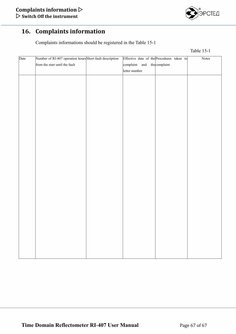
16. Complaints information
Complaints informations should be registered in the Table 15-1
Table 15-1
Date Number of RI-407 operation hours
from the start until the fault
Short fault description Effective date of the
complaint and the
letter number
Procedures taken to
complaint
Notes