Embed Size (px)
Citation preview
TIFFRevision 6.0Final — June 3, 1992
Author/Editor/Arbitrator: Steve Carlsen, Principal Engineer, Aldus Corporation
Aldus Developers DeskAldus Corporation411 First Avenue SouthSeattle, WA 98104-2871CompuServe: GO ALDSVC, Message Section #10Applelink: Aldus Developers Icon
For a copy of the TIFF 6.0 specification, call (206) 628-6593.
If you have questions about the contents of this specification, see page 8.
160-640M
TIFF 6.0 Specification Final—June 3, 1992
2
Copyright 1986-1988, 1992 Aldus Corporation. Permission to copy without fee all or partof this material is granted provided that the copies are not made or distributed fordirect commercial advantage and the Aldus copyright notice appears. If the major-ity of the document is copied or redistributed, it must be distributed verbatim,without repagination or reformatting. To copy otherwise requires specific permis-sion from the Aldus Corporation.
Licenses and TrademarksAldus and PageMaker are registered trademarks and TIFF is a trademark of AldusCorporation. Apple and Macintosh are registered trademarks of Apple Computer,Inc. MS-DOS is a registered trademark of Microsoft Corporation. UNIX is atrademark of Bell Laboratories. CompuServe is a registered trademark ofCompuServe Inc. PostScript is a registered trademark of Adobe Systems Inc. andall references to PostScript in this document are references to either the PostScriptinterpreter or language. Kodak and PhotoYCC are trademarks of Eastman KodakCompany.
Rather than put a trademark symbol in every occurrence of other trademarkednames, we state that we are using the names only in an editorial fashion, and to thebenefit of the trademark owner, with no intention of infringement of the trade-mark.
AcknowledgmentsThis specification is the result of much hard work by many people.
Some of the sections in Part 2 were written by a number of outside contributors:
Ed Beeman, Hewlett Packard
Nancy Cam, Silicon Graphics
Dennis Hamilton, Xerox
Eric Hamilton, C-Cube
Sam Leffler, Silicon Graphics
Chris and Dan Sears
Other primary reviewers and TAC meeting participants include representativesfrom Apple, Camex, Crosfield, Digital Optics Limited, Frame, IBM, Interleaf,Island Graphics, Kodak, Linotype-Hell, Quark, Sun Microsystems, Time Arts,US West, and Wang. Many thanks to all for lending their time and talents to thiseffort.
No document this large can completely satisfy everyone, but we have all workedhard to strike an effective balance between power and simplicity, between formal-ity and approachability, and between flexibility and constraints.
Production NotesThis document was created electronically using Aldus PageMaker 4.2.
TIFF 6.0 Specification Final—June 3, 1992
3
Contents
Introduction ....................................................................................................................4About this Specification ......................................................................4
Revision Notes .....................................................................................6
TIFF Administration .............................................................................8Information and Support .........................................................................8Private Fields and Values.......................................................................8Submitting a Proposal ............................................................................9The TIFF Advisory Committee ...............................................................9Other TIFF Extensions ...........................................................................9
Part 1: Baseline TIFF ....................................................................................................11Section 1: Notation ............................................................................12
Section 2: TIFF Structure...................................................................13
Section 3: Bilevel Images ..................................................................17
Section 4: Grayscale Images ............................................................22
Section 5: Palette-color Images ........................................................23
Section 6: RGB Full Color Images ....................................................24
Section 7: Additional Baseline TIFF Requirements ........................26
Section 8: Baseline Field Reference Guide .....................................28
Section 9: PackBits Compression ....................................................42
Section 10: Modified Huffman Compression ...................................43
Part 2: TIFF Extensions ..............................................................................................48Section 11: CCITT Bilevel Encodings ..............................................49
Section 12: Document Storage and Retrieval..................................55
Section 13: LZW Compression .........................................................57
Section 14: Differencing Predictor ...................................................64
Section 15: Tiled Images ...................................................................66
Section 16: CMYK Images .................................................................69
Section 17: HalftoneHints ..................................................................72
Section 18: Associated Alpha Handling...........................................77
Section 19: Data Sample Format ......................................................80
Section 20: RGB Image Colorimetry ................................................82
Section 21: YCbCr Images ................................................................89
Section 22: JPEG Compression .......................................................95
Section 23: CIE L*a*b* Images ........................................................110
Part 3: Appendices ....................................................................................................116Appendix A: TIFF Tags Sorted by Number ....................................117
Appendix B: Operating System Considerations ...........................119
Index ............................................................................................................................120
TIFF 6.0 Specification Final—June 3, 1992
4
Introduction
About this Specification
This document describes TIFF, a tag-based file format for storing and interchang-ing raster images.
History
The first version of the TIFF specification was published by Aldus Corporation inthe fall of 1986, after a series of meetings with various scanner manufacturers andsoftware developers. It did not have a revision number but should have been la-beled Revision 3.0 since there were two major earlier draft releases.
Revision 4.0 contained mostly minor enhancements and was released in April1987. Revision 5.0, released in October 1988, added support for palette colorimages and LZW compression.
Scope
TIFF describes image data that typically comes from scanners, frame grabbers,and paint- and photo-retouching programs.
TIFF is not a printer language or page description language. The purpose of TIFFis to describe and store raster image data.
A primary goal of TIFF is to provide a rich environment within which applica-tions can exchange image data. This richness is required to take advantage of thevarying capabilities of scanners and other imaging devices.
Though TIFF is a rich format, it can easily be used for simple scanners and appli-cations as well because the number of required fields is small.
TIFF will be enhanced on a continuing basis as new imaging needs arise. A highpriority has been given to structuring TIFF so that future enhancements can beadded without causing unnecessary hardship to developers.
TIFF 6.0 Specification Final—June 3, 1992
5
Features
• TIFF is capable of describing bilevel, grayscale, palette-color, and full-colorimage data in several color spaces.
• TIFF includes a number of compression schemes that allow developers tochoose the best space or time tradeoff for their applications.
• TIFF is not tied to specific scanners, printers, or computer display hardware.
• TIFF is portable. It does not favor particular operating systems, file systems,compilers, or processors.
• TIFF is designed to be extensible—to evolve gracefully as new needs arise.
• TIFF allows the inclusion of an unlimited amount of private or special-purposeinformation.
TIFF 6.0 Specification Final—June 3, 1992
6
Revision Notes
This revision replaces TIFF Revision 5.0.
Paragraphs that contain new or substantially-changed information are shown initalics.
New Features in Revision 6.0
Major enhancements to TIFF 6.0 are described in Part 2. They include:
• CMYK image definition
• A revised RGB Colorimetry section.
• YCbCr image definition
• CIE L*a*b* image definition
• Tiled image definition
• JPEG compression
Clarifications
• The LZW compression section more clearly explains when to switch the cod-ing bit length.
• The interaction between Compression=2 (CCITT Huffman) andPhotometricInterpretation was clarified.
• The data organization of uncompressed data (Compression=1) whenBitsPerSample is greater than 8 was clarified. See the Compression field de-scription.
• The discussion of CCITT Group 3 and Group 4 bilevel image encodings wasclarified and expanded, and Group3Options and Group4Options fields wererenamed T4Options and T6Options. See Section 11.
Organizational Changes
• To make the organization more consistent and expandable, appendices weretransformed into numbered sections.
• The document was divided into two parts—Baseline and Extensions—to helpdevelopers make better and more consistent implementation choices. Part 1,the Baseline section, describes those features that all general-purpose TIFFreaders should support. Part 2, the Extensions section, describes a number offeatures that can be used by special or advanced applications.
• An index and table of contents were added.
TIFF 6.0 Specification Final—June 3, 1992
7
Changes in Requirements
• To illustrate a Baseline TIFF file earlier in the document, the material fromAppendix G (“TIFF Classes”) in Revision 5 was integrated into the main bodyof the specification . As part of this integration, the TIFF Classes terminologywas replaced by the more monolithic Baseline TIFF terminology. The intentwas to further encourage all mainstream TIFF readers to support the BaselineTIFF requirements for bilevel, grayscale, RGB, and palette-color images.
• Due to licensing issues, LZW compression support was moved out of the “Part1: Baseline TIFF” and into “Part 2: Extensions.”
• Baseline TIFF requirements for bit depths in palette-color images were weak-ened a bit.
Changes in Terminology
In previous versions of the specification, the term “tag” reffered both to the identi-fying number of a TIFF field and to the entire field. In this version, the term “tag”refers only to the identifying number. The term “field” refers to the entire field,including the value.
Compatibility
Every attempt has been made to add functionality in such a way as to minimizecompatibility problems with files and software that were based on earlier versionsof the TIFF specification. The goal is that TIFF files should never become obso-lete and that TIFF software should not have to be revised more frequently thanabsolutely necessary. In particular, Baseline TIFF 6.0 files will generally be read-able even by older applications that assume TIFF 5.0 or an earlier version of thespecification.
However, TIFF 6.0 files that use one of the major new extensions, such as a newcompression scheme or color space, will not be successfully read by older soft-ware. In such cases, the older applications must gracefully give up and refuse toimport the image, providing the user with a reasonably informative message.
TIFF 6.0 Specification Final—June 3, 1992
8
TIFF Administration
Information and Support
The most recent version of the TIFF specification in PostScript format is availableon CompuServe ("Go ALDSVC", Library 10) and on AppleLink (Aldus Devel-opers Icon). Sample TIFF files and other TIFF developer information can also befound at these locations.
The Aldus CompuServe forum (Go ALDSVC) can also be used to post messagesto other TIFF developers, enabling developers to help each other.
Because of the tremendous growth in the usage of TIFF, Aldus is no longer able toprovide a general consulting service for TIFF implementors. TIFF developers areencouraged to study sample TIFF files, read TIFF documentation thoroughly, andwork with developers of other products that are important to you.
Most companies that use TIFF can answer questions about support for TIFF intheir products. Contact the appropriate product manager or developer supportservice group.
If you are an experienced TIFF developer and are interested in contract program-ming for other developers, please contact Aldus. Aldus can give your name toothers that might need your services.
Private Fields and Values
An organization might wish to store information meaningful to only that organi-zation in a TIFF file. Tags numbered 32768 or higher, sometimes called privatetags, are reserved for that purpose.
Upon request, the TIFF administrator (the Aldus Developers Desk) will allocateand register a block of private tags for an organization, to avoid possible conflictswith other organizations. Tags are normally allocated in blocks of five or less.You do not need to tell the TIFF administrator or anyone else what you plan to usethem for.
Private enumerated values can be accommodated in a similar fashion. For ex-ample, you may wish to experiment with a new compression scheme within TIFF.Enumeration constants numbered 32768 or higher are reserved for private usage.Upon request, the administrator will allocate and register one or more enumeratedvalues for a particular field (Compression, in our example), to avoid possibleconflicts.
Tags and values allocated in the private number range are not prohibited frombeing included in a future revision of this specification. Several such instancesexist in the TIFF specification.
Do not choose your own tag numbers. Doing so could cause serious compatibilityproblems in the future.
TIFF 6.0 Specification Final—June 3, 1992
9
If you need more than 5 or 10 tags, Aldus suggests that you reserve a single pri-vate tag, define it as a LONG, and use its value as a pointer (offset) to a privateIFD or other data structure of your choosing. Within that IFD, you can use what-ever tags you want, since no one else will know that it is an IFD unless you tellthem. This gives you some 65,000 private tags.
Submitting a Proposal
Any person or group that wants to propose a change or addition to the TIFF speci-fication should prepare a proposal that includes the following information:
• Name of the person or group making the request, and your affiliation.
• The reason for the request.
• A list of changes exactly as you propose that they appear in the specification.Use inserts, callouts, or other obvious editorial techniques to indicate areas ofchange, and number each change.
• Discussion of the potential impact on the installed base.
• A list of contacts outside your company that support your position. Includetheir affiliation.
Please send your proposal to Internet address: [email protected]. (FromAppleLink, you can send to: [email protected]@internet#. FromCompuServe, you can send to: >INTERNET:[email protected].) Do not sendTIFF implementation questions to this address; see above for Aldus DevelopersDesk TIFF support policies.
The TIFF Advisory Committee
The TIFF Advisory Committee is a working group of TIFF experts from a numberof hardware and software manufacturers. It was formed in the spring of 1991 toprovide a forum for debating and refining proposals for the 6.0 release of the TIFFspecification. It is not clear if this will be an ongoing group or if it will go into aperiod of hibernation until pressure builds for another major release of the TIFFspecification.
If you are a TIFF expert and think you have the time and interest to work on thiscommittee, contact the Aldus Developers Desk for further information. For theTIFF 6.0 release, the group met every two or three months, usually on the westcoast of the U.S. Accessibility via Internet e-mail (or AppleLink or CompuServe,which have gateways to the Internet) is a requirement for membership, since thathas proven to be an invaluable means for getting work done between meetings.
Other TIFF Extensions
The Aldus TIFF sections on CompuServe and AppleLink will contain proposedextensions from Aldus and other companies that are not yet approved by the TIFFAdvisory Committee.
Many of these proposals will never be approved or even considered by the TIFFAdvisory Committee, especially if they represent specialized uses of TIFF that do
TIFF 6.0 Specification Final—June 3, 1992
10
not fall within the domain of publishing or general graphics or picture inter-change. Use them at your own risk; it is unlikely that these features will be widelysupported. And if you do write files that incorporate these extensions, be sure tonot call them TIFF files or to mark them in some way so that they will not beconfused with mainstream TIFF files.
Aldus will provide a place on Compuserve and Applelink for storing such docu-ments. Contact the Aldus Developers Desk for instructions. We recommend thatall submissions be in the form of simple text or portable PostScript form that canbe downloaded to any PostScript printer in any computing environment.
If a non-Aldus contact name is listed, please use that contact rather than Aldus forsubmitting requests for future enhancements to that extension.
TIFF 6.0 Specification Final—June 3, 1992
11
Part 1: Baseline TIFFThe TIFF specification is divided into two parts. Part 1 describes Baseline TIFF.Baseline TIFF is the core of TIFF, the essentials that all mainstream TIFF devel-opers should support in their products.
TIFF 6.0 Specification Final—June 3, 1992
12
Section 1: Notation
Decimal and Hexadecimal
Unless otherwise noted, all numeric values in this document are expressed indecimal. (“.H” is appended to hexidecimal values.)
Compliance
Is and shall indicate mandatory requirements. All compliant writers and readersmust meet the specification.
Should indicates a recommendation.
May indicates an option.
Features designated ‘not recommended for general data interchange’ are consid-ered extensions to Baseline TIFF. Files that use such features shall be designated“Extended TIFF 6.0” files, and the particular extensions used should be docu-mented. A Baseline TIFF 6.0 reader is not required to support any extensions.
TIFF 6.0 Specification Final—June 3, 1992
13
Section 2: TIFF Structure
TIFF is an image file format. In this document, a file is defined to be a sequence of8-bit bytes, where the bytes are numbered from 0 to N. The largest possible TIFFfile is 2**32 bytes in length.
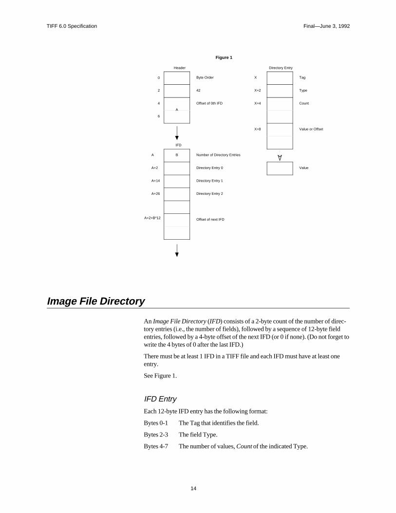
A TIFF file begins with an 8-byte image file header that points to an image filedirectory (IFD). An image file directory contains information about the image, aswell as pointers to the actual image data.
The following paragraphs describe the image file header and IFD in more detail.
See Figure 1.
Image File Header
A TIFF file begins with an 8-byte image file header, containing the followinginformation:
Bytes 0-1: The byte order used within the file. Legal values are:
“II” (4949.H)
“MM” (4D4D.H)
In the “II” format, byte order is always from the least significant byte to the mostsignificant byte, for both 16-bit and 32-bit integers This is called little-endian byteorder. In the “MM” format, byte order is always from most significant to leastsignificant, for both 16-bit and 32-bit integers. This is called big-endian byteorder.
Bytes 2-3 An arbitrary but carefully chosen number (42) that further identifies the file as aTIFF file.
The byte order depends on the value of Bytes 0-1.
Bytes 4-7 The offset (in bytes) of the first IFD. The directory may be at any location in thefile after the header but must begin on a word boundary. In particular, an ImageFile Directory may follow the image data it describes. Readers must follow thepointers wherever they may lead.
The term byte offset is always used in this document to refer to a location withrespect to the beginning of the TIFF file. The first byte of the file has an offset of0.
TIFF 6.0 Specification Final—June 3, 1992
14
0
2
4
6
Byte Order
42
Offset of 0th IFD
Figure 1
Header
A
A
A+2
A+14
A+26
A+2+B*12
B Number of Directory Entries
Directory Entry 0
Directory Entry 1
Directory Entry 2
Offset of next IFD
IFD
X
X+2
X+4
X+8
Tag
Type
Count
Value or Offset
Directory Entry
Value
Image File Directory
An Image File Directory (IFD) consists of a 2-byte count of the number of direc-tory entries (i.e., the number of fields), followed by a sequence of 12-byte fieldentries, followed by a 4-byte offset of the next IFD (or 0 if none). (Do not forget towrite the 4 bytes of 0 after the last IFD.)
There must be at least 1 IFD in a TIFF file and each IFD must have at least oneentry.
See Figure 1.
IFD Entry
Each 12-byte IFD entry has the following format:
Bytes 0-1 The Tag that identifies the field.
Bytes 2-3 The field Type.
Bytes 4-7 The number of values, Count of the indicated Type.
TIFF 6.0 Specification Final—June 3, 1992
15
Bytes 8-11 The Value Offset, the file offset (in bytes) of the Value for the field.The Value is expected to begin on a word boundary; the correspond-ing Value Offset will thus be an even number. This file offset maypoint anywhere in the file, even after the image data.
IFD Terminology
A TIFF field is a logical entity consisting of TIFF tag and its value. This logicalconcept is implemented as an IFD Entry, plus the actual value if it doesn’t fit intothe value/offset part, the last 4 bytes of the IFD Entry. The terms TIFF field andIFD entry are interchangeable in most contexts.
Sort Order
The entries in an IFD must be sorted in ascending order by Tag. Note that this isnot the order in which the fields are described in this document. The Values towhich directory entries point need not be in any particular order in the file.
Value/Offset
To save time and space the Value Offset contains the Value instead of pointing tothe Value if and only if the Value fits into 4 bytes. If the Value is shorter than 4bytes, it is left-justified within the 4-byte Value Offset, i.e., stored in the lower-numbered bytes. Whether the Value fits within 4 bytes is determined by the Typeand Count of the field.
Count
Count—called Length in previous versions of the specification—is the number ofvalues. Note that Count is not the total number of bytes. For example, a single 16-bit word (SHORT) has a Count of 1; not 2.
Types
The field types and their sizes are:
1 = BYTE 8-bit unsigned integer.
2 = ASCII 8-bit byte that contains a 7-bit ASCII code; the last bytemust be NUL (binary zero).
3 = SHORT 16-bit (2-byte) unsigned integer.
4 = LONG 32-bit (4-byte) unsigned integer.
5 = RATIONAL Two LONGs: the first represents the numerator of afraction; the second, the denominator.
The value of the Count part of an ASCII field entry includes the NUL. If paddingis necessary, the Count does not include the pad byte. Note that there is no initial“count byte” as in Pascal-style strings.
TIFF 6.0 Specification Final—June 3, 1992
16
Any ASCII field can contain multiple strings, each terminated with a NUL. Asingle string is preferred whenever possible. The Count for multi-string fields isthe number of bytes in all the strings in that field plus their terminating NULbytes. Only one NUL is allowed between strings, so that the strings following thefirst string will often begin on an odd byte.
The reader must check the type to verify that it contains an expected value. TIFFcurrently allows more than 1 valid type for some fields. For example, ImageWidthand ImageLength are usually specified as having type SHORT. But images withmore than 64K rows or columns must use the LONG field type.
TIFF readers should accept BYTE, SHORT, or LONG values for any unsignedinteger field. This allows a single procedure to retrieve any integer value, makesreading more robust, and saves disk space in some situations.
In TIFF 6.0, some new field types have been defined:
6 = SBYTE An 8-bit signed (twos-complement) integer.
7 = UNDEFINED An 8-bit byte that may contain anything, depending onthe definition of the field.
8 = SSHORT A 16-bit (2-byte) signed (twos-complement) integer.
9 = SLONG A 32-bit (4-byte) signed (twos-complement) integer.
10 = SRATIONAL Two SLONG’s: the first represents the numerator of afraction, the second the denominator.
11 = FLOAT Single precision (4-byte) IEEE format.
12 = DOUBLE Double precision (8-byte) IEEE format.
These new field types are also governed by the byte order (II or MM) in the TIFFheader.
Warning: It is possible that other TIFF field types will be added in the future.Readers should skip over fields containing an unexpected field type.
Fields are arrays
Each TIFF field has an associated Count. This means that all fields are actuallyone-dimensional arrays, even though most fields contain only a single value.
For example, to store a complicated data structure in a single private field, usethe UNDEFINED field type and set the Count to the number of bytes required tohold the data structure.
Multiple Images per TIFF File
There may be more than one IFD in a TIFF file. Each IFD defines a subfile. Onepotential use of subfiles is to describe related images, such as the pages of a fac-simile transmission. A Baseline TIFF reader is not required to read any IFDsbeyond the first one.
TIFF 6.0 Specification Final—June 3, 1992
17
Section 3: Bilevel Images
Now that the overall TIFF structure has been described, we can move on to fillingthe structure with actual fields (tags and values) that describe raster image data.
To make all of this clearer, the discussion will be organized according to the fourBaseline TIFF image types: bilevel, grayscale, palette-color, and full-color im-ages. This section describes bilevel images.
Fields required to describe bilevel images are introduced and described brieflyhere. Full descriptions of each field can be found in Section 8.
Color
A bilevel image contains two colors—black and white. TIFF allows an applica-tion to write out bilevel data in either a white-is-zero or black-is-zero format. Thefield that records this information is called PhotometricInterpretation.
PhotometricInterpretationTag = 262 (106.H)
Type = SHORT
Values:
0 = WhiteIsZero. For bilevel and grayscale images: 0 is imaged as white. The maxi-mum value is imaged as black. This is the normal value for Compression=2.
1 = BlackIsZero. For bilevel and grayscale images: 0 is imaged as black. The maxi-mum value is imaged as white. If this value is specified for Compression=2, theimage should display and print reversed.
Compression
Data can be stored either compressed or uncompressed.
CompressionTag = 259 (103.H)
Type = SHORT
Values:
1 = No compression, but pack data into bytes as tightly as possible, leaving no unusedbits (except at the end of a row). The component values are stored as an array oftype BYTE. Each scan line (row) is padded to the next BYTE boundary.
2 = CCITT Group 3 1-Dimensional Modified Huffman run length encoding. See
TIFF 6.0 Specification Final—June 3, 1992
18
Section 10 for a description of Modified Huffman Compression.
32773 = PackBits compression, a simple byte-oriented run length scheme. See thePackBits section for details.
Data compression applies only to raster image data. All other TIFF fields areunaffected.
Baseline TIFF readers must handle all three compression schemes.
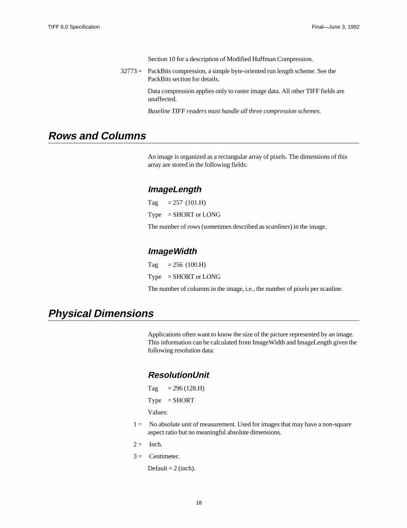
Rows and Columns
An image is organized as a rectangular array of pixels. The dimensions of thisarray are stored in the following fields:
ImageLengthTag = 257 (101.H)
Type = SHORT or LONG
The number of rows (sometimes described as scanlines) in the image.
ImageWidthTag = 256 (100.H)
Type = SHORT or LONG
The number of columns in the image, i.e., the number of pixels per scanline.
Physical Dimensions
Applications often want to know the size of the picture represented by an image.This information can be calculated from ImageWidth and ImageLength given thefollowing resolution data:
ResolutionUnitTag = 296 (128.H)
Type = SHORT
Values:
1 = No absolute unit of measurement. Used for images that may have a non-squareaspect ratio but no meaningful absolute dimensions.
2 = Inch.
3 = Centimeter.
Default = 2 (inch).
TIFF 6.0 Specification Final—June 3, 1992
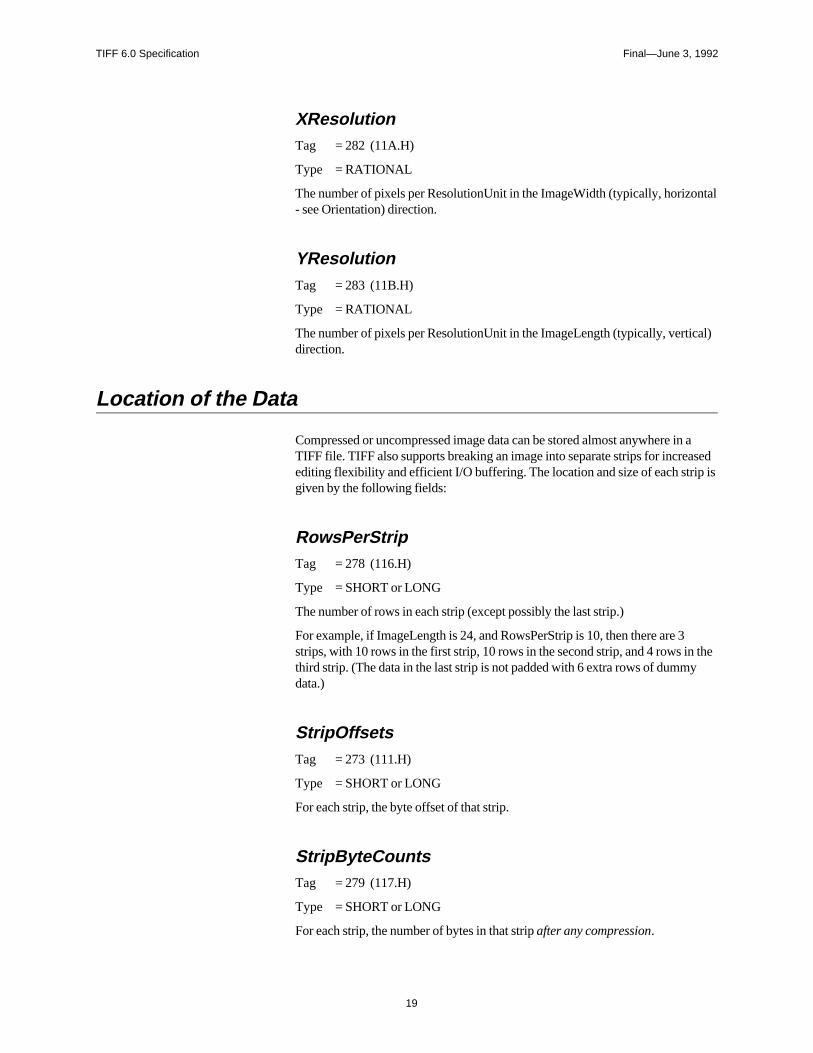
19
XResolutionTag = 282 (11A.H)
Type = RATIONAL
The number of pixels per ResolutionUnit in the ImageWidth (typically, horizontal- see Orientation) direction.
YResolutionTag = 283 (11B.H)
Type = RATIONAL
The number of pixels per ResolutionUnit in the ImageLength (typically, vertical)direction.
Location of the Data
Compressed or uncompressed image data can be stored almost anywhere in aTIFF file. TIFF also supports breaking an image into separate strips for increasedediting flexibility and efficient I/O buffering. The location and size of each strip isgiven by the following fields:
RowsPerStripTag = 278 (116.H)
Type = SHORT or LONG
The number of rows in each strip (except possibly the last strip.)
For example, if ImageLength is 24, and RowsPerStrip is 10, then there are 3strips, with 10 rows in the first strip, 10 rows in the second strip, and 4 rows in thethird strip. (The data in the last strip is not padded with 6 extra rows of dummydata.)
StripOffsetsTag = 273 (111.H)
Type = SHORT or LONG
For each strip, the byte offset of that strip.
StripByteCountsTag = 279 (117.H)
Type = SHORT or LONG
For each strip, the number of bytes in that strip after any compression.
TIFF 6.0 Specification Final—June 3, 1992
20
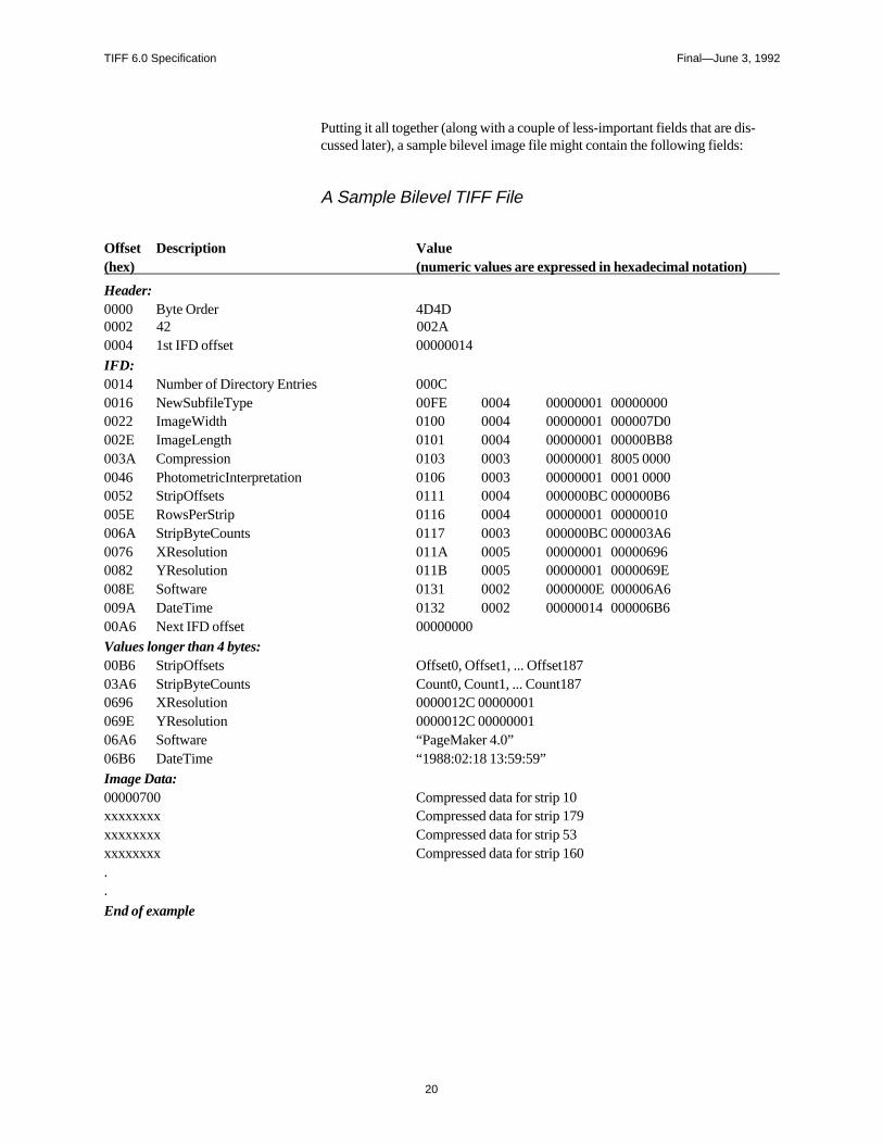
Putting it all together (along with a couple of less-important fields that are dis-cussed later), a sample bilevel image file might contain the following fields:
A Sample Bilevel TIFF File
Offset Description Value(hex) (numeric values are expressed in hexadecimal notation)
Header:0000 Byte Order 4D4D0002 42 002A0004 1st IFD offset 00000014IFD:0014 Number of Directory Entries 000C0016 NewSubfileType 00FE 0004 00000001 000000000022 ImageWidth 0100 0004 00000001 000007D0002E ImageLength 0101 0004 00000001 00000BB8003A Compression 0103 0003 00000001 8005 00000046 PhotometricInterpretation 0106 0003 00000001 0001 00000052 StripOffsets 0111 0004 000000BC 000000B6005E RowsPerStrip 0116 0004 00000001 00000010006A StripByteCounts 0117 0003 000000BC 000003A60076 XResolution 011A 0005 00000001 000006960082 YResolution 011B 0005 00000001 0000069E008E Software 0131 0002 0000000E 000006A6009A DateTime 0132 0002 00000014 000006B600A6 Next IFD offset 00000000Values longer than 4 bytes:00B6 StripOffsets Offset0, Offset1, ... Offset18703A6 StripByteCounts Count0, Count1, ... Count1870696 XResolution 0000012C 00000001069E YResolution 0000012C 0000000106A6 Software “PageMaker 4.0”06B6 DateTime “1988:02:18 13:59:59”Image Data:00000700 Compressed data for strip 10xxxxxxxx Compressed data for strip 179xxxxxxxx Compressed data for strip 53xxxxxxxx Compressed data for strip 160..
End of example
TIFF 6.0 Specification Final—June 3, 1992
21
Comments on the Bilevel Image Example
• The IFD in this example starts at 14h. It could have started anywhere in the fileproviding the offset was an even number greater than or equal to 8 (since theTIFF header is always the first 8 bytes of a TIFF file).
• With 16 rows per strip, there are 188 strips in all.
• The example uses a number of optional fields such as DateTime. TIFF readersmust safely skip over these fields if they do not understand or do not wish touse the information. Baseline TIFF readers must not require that such fields bepresent.
• To make a point, this example has highly-fragmented image data. The strips ofthe image are not in sequential order. The point of this example is to illustratethat strip offsets must not be ignored. Never assume that strip N+1 follows stripN on disk. It is not required that the image data follow the IFD information.
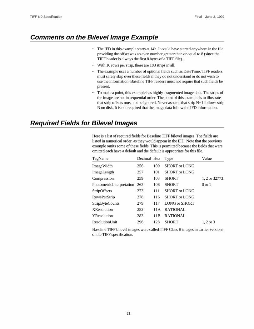
Required Fields for Bilevel Images
Here is a list of required fields for Baseline TIFF bilevel images. The fields arelisted in numerical order, as they would appear in the IFD. Note that the previousexample omits some of these fields. This is permitted because the fields that wereomitted each have a default and the default is appropriate for this file.
TagName Decimal Hex Type Value
ImageWidth 256 100 SHORT or LONG
ImageLength 257 101 SHORT or LONG
Compression 259 103 SHORT 1, 2 or 32773
PhotometricInterpretation 262 106 SHORT 0 or 1
StripOffsets 273 111 SHORT or LONG
RowsPerStrip 278 116 SHORT or LONG
StripByteCounts 279 117 LONG or SHORT
XResolution 282 11A RATIONAL
YResolution 283 11B RATIONAL
ResolutionUnit 296 128 SHORT 1, 2 or 3
Baseline TIFF bilevel images were called TIFF Class B images in earlier versionsof the TIFF specification.
TIFF 6.0 Specification Final—June 3, 1992
22
Section 4: Grayscale Images
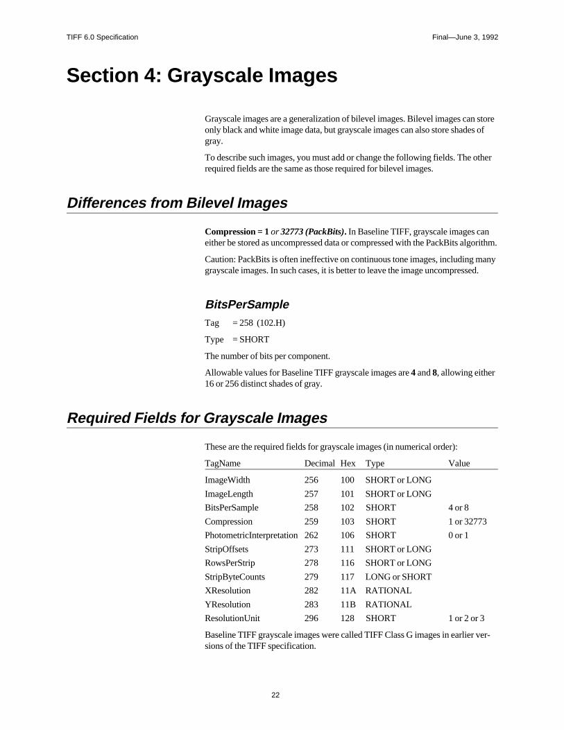
Grayscale images are a generalization of bilevel images. Bilevel images can storeonly black and white image data, but grayscale images can also store shades ofgray.
To describe such images, you must add or change the following fields. The otherrequired fields are the same as those required for bilevel images.
Differences from Bilevel Images
Compression = 1 or 32773 (PackBits). In Baseline TIFF, grayscale images caneither be stored as uncompressed data or compressed with the PackBits algorithm.
Caution: PackBits is often ineffective on continuous tone images, including manygrayscale images. In such cases, it is better to leave the image uncompressed.
BitsPerSampleTag = 258 (102.H)
Type = SHORT
The number of bits per component.
Allowable values for Baseline TIFF grayscale images are 4 and 8, allowing either16 or 256 distinct shades of gray.
Required Fields for Grayscale Images
These are the required fields for grayscale images (in numerical order):
TagName Decimal Hex Type Value
ImageWidth 256 100 SHORT or LONG
ImageLength 257 101 SHORT or LONG
BitsPerSample 258 102 SHORT 4 or 8
Compression 259 103 SHORT 1 or 32773
PhotometricInterpretation 262 106 SHORT 0 or 1
StripOffsets 273 111 SHORT or LONG
RowsPerStrip 278 116 SHORT or LONG
StripByteCounts 279 117 LONG or SHORT
XResolution 282 11A RATIONAL
YResolution 283 11B RATIONAL
ResolutionUnit 296 128 SHORT 1 or 2 or 3
Baseline TIFF grayscale images were called TIFF Class G images in earlier ver-sions of the TIFF specification.
TIFF 6.0 Specification Final—June 3, 1992
23
Section 5: Palette-color Images
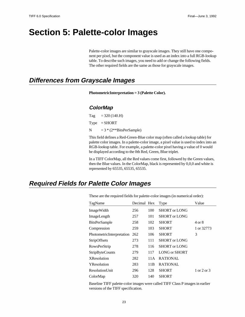
Palette-color images are similar to grayscale images. They still have one compo-nent per pixel, but the component value is used as an index into a full RGB-lookuptable. To describe such images, you need to add or change the following fields.The other required fields are the same as those for grayscale images.
Differences from Grayscale Images
PhotometricInterpretation = 3 (Palette Color).
ColorMapTag = 320 (140.H)
Type = SHORT
N = 3 * (2**BitsPerSample)
This field defines a Red-Green-Blue color map (often called a lookup table) forpalette color images. In a palette-color image, a pixel value is used to index into anRGB-lookup table. For example, a palette-color pixel having a value of 0 wouldbe displayed according to the 0th Red, Green, Blue triplet.
In a TIFF ColorMap, all the Red values come first, followed by the Green values,then the Blue values. In the ColorMap, black is represented by 0,0,0 and white isrepresented by 65535, 65535, 65535.
Required Fields for Palette Color Images
These are the required fields for palette-color images (in numerical order):
TagName Decimal Hex Type Value
ImageWidth 256 100 SHORT or LONG
ImageLength 257 101 SHORT or LONG
BitsPerSample 258 102 SHORT 4 or 8
Compression 259 103 SHORT 1 or 32773
PhotometricInterpretation 262 106 SHORT 3
StripOffsets 273 111 SHORT or LONG
RowsPerStrip 278 116 SHORT or LONG
StripByteCounts 279 117 LONG or SHORT
XResolution 282 11A RATIONAL
YResolution 283 11B RATIONAL
ResolutionUnit 296 128 SHORT 1 or 2 or 3
ColorMap 320 140 SHORT
Baseline TIFF palette-color images were called TIFF Class P images in earlierversions of the TIFF specification.
TIFF 6.0 Specification Final—June 3, 1992
24
Section 6: RGB Full Color Images
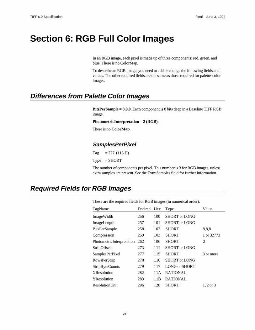
In an RGB image, each pixel is made up of three components: red, green, andblue. There is no ColorMap.
To describe an RGB image, you need to add or change the following fields andvalues. The other required fields are the same as those required for palette-colorimages.
Differences from Palette Color Images
BitsPerSample = 8,8,8. Each component is 8 bits deep in a Baseline TIFF RGBimage.
PhotometricInterpretation = 2 (RGB).
There is no ColorMap.
SamplesPerPixelTag = 277 (115.H)
Type = SHORT
The number of components per pixel. This number is 3 for RGB images, unlessextra samples are present. See the ExtraSamples field for further information.
Required Fields for RGB Images
These are the required fields for RGB images (in numerical order):
TagName Decimal Hex Type Value
ImageWidth 256 100 SHORT or LONG
ImageLength 257 101 SHORT or LONG
BitsPerSample 258 102 SHORT 8,8,8
Compression 259 103 SHORT 1 or 32773
PhotometricInterpretation 262 106 SHORT 2
StripOffsets 273 111 SHORT or LONG
SamplesPerPixel 277 115 SHORT 3 or more
RowsPerStrip 278 116 SHORT or LONG
StripByteCounts 279 117 LONG or SHORT
XResolution 282 11A RATIONAL
YResolution 283 11B RATIONAL
ResolutionUnit 296 128 SHORT 1, 2 or 3

TIFF 6.0 Specification Final—June 3, 1992
25
The BitsPerSample values listed above apply only to the main image data. IfExtraSamples are present, the appropriate BitsPerSample values for thosesamples must also be included.
Baseline TIFF RGB images were called TIFF Class R images in earlier versionsof the TIFF specification.
TIFF 6.0 Specification Final—June 3, 1992
26
Section 7: Additional Baseline TIFFRequirements
This section describes characteristics required of all Baseline TIFF files.
General Requirements
Options. Where there are options, TIFF writers can use whichever they want.Baseline TIFF readers must be able to handle all of them.
Defaults. TIFF writers may, but are not required to, write out a field that has adefault value, if the default value is the one desired. TIFF readers must be pre-pared to handle either situation.
Other fields. TIFF readers must be prepared to encounter fields other than thoserequired in TIFF files. TIFF writers are allowed to write optional fields such asMake, Model, and DateTime, and TIFF readers may use such fields if they exist.TIFF readers must not, however, refuse to read the file if such optional fields donot exist. TIFF readers must also be prepared to encounter and ignore privatefields not described in the TIFF specification.
‘MM’ and ‘II’ byte order. TIFF readers must be able to handle both byte orders.TIFF writers can do whichever is most convenient or efficient.
Multiple subfiles. TIFF readers must be prepared for multiple images (subfiles)per TIFF file, although they are not required to do anything with images after thefirst one. TIFF writers are required to write a long word of 0 after the last IFD (tosignal that this is the last IFD), as described earlier in this specification.
If multiple subfiles are written, the first one must be the full-resolution image.Subsequent images, such as reduced-resolution images, may be in any order in theTIFF file. If a reader wants to use such images, it must scan the correspondingIFD’s before deciding how to proceed.
TIFF Editors. Editors—applications that modify TIFF files—have a few addi-tional requirements:
• TIFF editors must be especially careful about subfiles. If a TIFF editor edits afull-resolution subfile, but does not update an accompanying reduced-resolu-tion subfile, a reader that uses the reduced-resolution subfile for screen displaywill display the wrong thing. So TIFF editors must either create a new reduced-resolution subfile when they alter a full-resolution subfile or they must deleteany subfiles that they aren’t prepared to deal with.
• A similar situation arises with the fields in an IFD. It is unnecessary—andpossibly dangerous—for an editor to copy fields it does not understand be-cause the editor might alter the file in a way that is incompatible with the un-known fields.
No Duplicate Pointers. No data should be referenced from more than one place.TIFF readers and editors are under no obligation to detect this condition andhandle it properly. This would not be a problem if TIFF files were read-only enti-
TIFF 6.0 Specification Final—June 3, 1992
27
ties, but they are not. This warning covers both TIFF field value offsets and fieldsthat are defined as offsets, such as StripOffsets.
Point to real data. All strip offsets must reference valid locations. (It is not legal touse an offset of 0 to mean something special.)
Beware of extra components. Some TIFF files may have more components perpixel than you think. A Baseline TIFF reader must skip over them gracefully,using the values of the SamplesPerPixel and BitsPerSample fields. For example,
TIFF 6.0 Specification Final—June 3, 1992
28
Section 8: Baseline Field Reference Guide
This section contains detailed information about all the Baseline fields defined inthis version of TIFF. A Baseline field is any field commonly found in a BaselineTIFF file, whether required or not.
For convenience, fields that were defined in earlier versions of the TIFF specifica-tion but are no longer generally recommended have also been included in thissection.
New fields that are associated with optional features are not listed in this section.See Part 2 for descriptions of these new fields. There is a complete list of all fieldsdescribed in this specification in Appendix A, and there are entries for all TIFFfields in the index.
More fields may be added in future versions. Whenever possible they will beadded in a way that allows old TIFF readers to read newer TIFF files.
The documentation for each field contains:
• the name of the field
• the Tag number
• the field Type
• the required Number of Values (N); i.e., the Count
• comments describing the field
• the default, if any
If the field does not exist, readers must assume the default value for the field.
Most of the fields described in this part of the document are not required or arerequired only for particular types of TIFF files. See the preceding sections for listsof required fields.
Before defining the fields, you must understand these basic concepts: A BaselineTIFF image is defined to be a two-dimensional array of pixels, each of whichconsists of one or more color components. Monochromatic data has one colorcomponent per pixel, while RGB color data has three color components per pixel.
The Fields
ArtistPerson who created the image.
Tag = 315 (13B.H)
Type = ASCII
Note: some older TIFF files used this tag for storing Copyright information.
TIFF 6.0 Specification Final—June 3, 1992
29
BitsPerSampleNumber of bits per component.
Tag = 258 (102.H)
Type = SHORT
N = SamplesPerPixel
Note that this field allows a different number of bits per component for each
component corresponding to a pixel. For example, RGB color data could use a
different number of bits per component for each of the three color planes. Most RGB
files will have the same number of BitsPerSample for each component. Even in this
case, the writer must write all three values.
Default = 1. See also SamplesPerPixel.
CellLengthThe length of the dithering or halftoning matrix used to create a dithered orhalftoned bilevel file.
Tag = 265 (109.H)
Type = SHORT
N = 1
This field should only be present if Threshholding = 2
No default. See also Threshholding.
CellWidthThe width of the dithering or halftoning matrix used to create a dithered orhalftoned bilevel file.Tag = 264 (108.H)
Type = SHORT
N = 1
No default. See also Threshholding.
ColorMapA color map for palette color images.
Tag = 320 (140.H)
Type = SHORT
N = 3 * (2**BitsPerSample)
This field defines a Red-Green-Blue color map (often called a lookup table) forpalette-color images. In a palette-color image, a pixel value is used to index intoan RGB lookup table. For example, a palette-color pixel having a value of 0would be displayed according to the 0th Red, Green, Blue triplet.
TIFF 6.0 Specification Final—June 3, 1992
30
In a TIFF ColorMap, all the Red values come first, followed by the Green values,then the Blue values. The number of values for each color is 2**BitsPerSample.Therefore, the ColorMap field for an 8-bit palette-color image would have 3 * 256values.
The width of each value is 16 bits, as implied by the type of SHORT. 0 representsthe minimum intensity, and 65535 represents the maximum intensity. Black isrepresented by 0,0,0, and white by 65535, 65535, 65535.
See also PhotometricInterpretation—palette color.
No default. ColorMap must be included in all palette-color images.
CompressionCompression scheme used on the image data.
Tag = 259 (103.H)
Type = SHORT
N = 1
1 = No compression, but pack data into bytes as tightly as possible leaving no unusedbits except at the end of a row.
If Then the sample values are stored as an array of type:
BitsPerSample = 16 for all samples SHORT
BitsPerSample = 32 for all samples LONG
Otherwise BYTE
Each row is padded to the next BYTE/SHORT/LONG boundary, consistent withthe preceding BitsPerSample rule.
If the image data is stored as an array of SHORTs or LONGs, the byte orderingmust be consistent with that specified in bytes 0 and 1 of the TIFF file header.Therefore, little-endian format files will have the least significant bytes precedingthe most significant bytes, while big-endian format files will have the oppositeorder.
If the number of bits per component is not a power of 2, and you are willing to give up
some space for better performance, use the next higher power of 2. For example, if
your data can be represented in 6 bits, set BitsPerSample to 8 instead of 6, and then
convert the range of the values from [0,63] to [0,255].
Rows must begin on byte boundaries. (SHORT boundaries if the data is stored asSHORTs, LONG boundaries if the data is stored as LONGs).
Some graphics systems require image data rows to be word-aligned or double-word-
aligned, and padded to word-boundaries or double-word boundaries. Uncompressed
TIFF rows will need to be copied into word-aligned or double-word-aligned row
buffers before being passed to the graphics routines in these environments.
2 = CCITT Group 3 1-Dimensional Modified Huffman run-length encoding. SeeSection 10. BitsPerSample must be 1, since this type of compression is definedonly for bilevel images.
TIFF 6.0 Specification Final—June 3, 1992
31
32773 = PackBits compression, a simple byte-oriented run-length scheme. See Section 9for details.
Data compression applies only to the image data, pointed to by StripOffsets.
Default = 1.
CopyrightCopyright notice.
Tag = 33432 (8298.H)
Type = ASCII
Copyright notice of the person or organization that claims the copyright to theimage. The complete copyright statement should be listed in this field includingany dates and statements of claims. For example, “Copyright, John Smith, 19xx.All rights reserved.”
DateTimeDate and time of image creation.
Tag = 306 (132.H)
Type = ASCII
N = 20
The format is: “YYYY:MM:DD HH:MM:SS”, with hours like those on a 24-hourclock, and one space character between the date and the time. The length of thestring, including the terminating NUL, is 20 bytes.
ExtraSamplesDescription of extra components.
Tag = 338 (152.H)
Type = SHORT
N = m
Specifies that each pixel has m extra components whose interpretation is definedby one of the values listed below. When this field is used, the SamplesPerPixelfield has a value greater than the PhotometricInterpretation field suggests.
For example, full-color RGB data normally has SamplesPerPixel=3. IfSamplesPerPixel is greater than 3, then the ExtraSamples field describes themeaning of the extra samples. If SamplesPerPixel is, say, 5 then ExtraSampleswill contain 2 values, one for each extra sample.
ExtraSamples is typically used to include non-color information, such as opacity,in an image. The possible values for each item in the field's value are:
0 = Unspecified data
1 = Associated alpha data (with pre-multiplied color)
TIFF 6.0 Specification Final—June 3, 1992
32
2 = Unassociated alpha data
Associated alpha data is opacity information; it is fully described in Section 21.Unassociated alpha data is transparency information that logically exists indepen-dent of an image; it is commonly called a soft matte. Note that including bothunassociated and associated alpha is undefined because associated alpha specifiesthat color components are pre-multiplied by the alpha component, whileunassociated alpha specifies the opposite.
By convention, extra components that are present must be stored as the “last com-ponents” in each pixel. For example, if SamplesPerPixel is 4 and there is 1 extracomponent, then it is located in the last component location (SamplesPerPixel-1)in each pixel.
Components designated as “extra” are just like other components in a pixel. Inparticular, the size of such components is defined by the value of theBitsPerSample field.
With the introduction of this field, TIFF readers must not assume a particularSamplesPerPixel value based on the value of the PhotometricInterpretation field.For example, if the file is an RGB file, SamplesPerPixel may be greater than 3.
The default is no extra samples. This field must be present if there are extrasamples.
See also SamplesPerPixel, AssociatedAlpha.
FillOrderThe logical order of bits within a byte.
Tag = 266 (10A.H)
Type = SHORT
N = 1
1 = pixels are arranged within a byte such that pixels with lower column values arestored in the higher-order bits of the byte.
1-bit uncompressed data example: Pixel 0 of a row is stored in the high-order bitof byte 0, pixel 1 is stored in the next-highest bit, ..., pixel 7 is stored in the low-order bit of byte 0, pixel 8 is stored in the high-order bit of byte 1, and so on.
CCITT 1-bit compressed data example: The high-order bit of the first compres-sion code is stored in the high-order bit of byte 0, the next-highest bit of the firstcompression code is stored in the next-highest bit of byte 0, and so on.
2 = pixels are arranged within a byte such that pixels with lower column values arestored in the lower-order bits of the byte.
We recommend that FillOrder=2 be used only in special-purpose applications. Itis easy and inexpensive for writers to reverse bit order by using a 256-byte lookuptable. FillOrder = 2 should be used only when BitsPerSample = 1 and the data iseither uncompressed or compressed using CCITT 1D or 2D compression, toavoid potentially ambigous situations.
Support for FillOrder=2 is not required in a Baseline TIFF compliant reader
Default is FillOrder = 1.
TIFF 6.0 Specification Final—June 3, 1992
33
FreeByteCountsFor each string of contiguous unused bytes in a TIFF file, the number of bytes inthe string.
Tag = 289 (121.H)
Type = LONG
Not recommended for general interchange.
See also FreeOffsets.
FreeOffsetsFor each string of contiguous unused bytes in a TIFF file, the byte offset of thestring.
Tag = 288 (120.H)
Type = LONG
Not recommended for general interchange.
See also FreeByteCounts.
GrayResponseCurveFor grayscale data, the optical density of each possible pixel value.
Tag = 291 (123.H)
Type = SHORT
N = 2**BitsPerSample
The 0th value of GrayResponseCurve corresponds to the optical density of a pixelhaving a value of 0, and so on.
This field may provide useful information for sophisticated applications, but it iscurrently ignored by most TIFF readers.
See also GrayResponseUnit, PhotometricInterpretation.
GrayResponseUnitThe precision of the information contained in the GrayResponseCurve.
Tag = 290 (122.H)
Type = SHORT
N = 1
Because optical density is specified in terms of fractional numbers, this field isnecessary to interpret the stored integer information. For example, ifGrayScaleResponseUnits is set to 4 (ten-thousandths of a unit), and aGrayScaleResponseCurve number for gray level 4 is 3455, then the resultingactual value is 0.3455.
Optical densitometers typically measure densities within the range of 0.0 to 2.0.
TIFF 6.0 Specification Final—June 3, 1992
34
1 = Number represents tenths of a unit.
2 = Number represents hundredths of a unit.
3 = Number represents thousandths of a unit.
4 = Number represents ten-thousandths of a unit.
5 = Number represents hundred-thousandths of a unit.
Modifies GrayResponseCurve.
See also GrayResponseCurve.
For historical reasons, the default is 2. However, for greater accuracy, 3 is recom-mended.
HostComputerThe computer and/or operating system in use at the time of image creation.
Tag = 316 (13C.H)
Type = ASCII
See also Make, Model, Software.
ImageDescriptionA string that describes the subject of the image.
Tag = 270 (10E.H)
Type = ASCII
For example, a user may wish to attach a comment such as “1988 company pic-nic” to an image.
ImageLengthThe number of rows of pixels in the image.
Tag = 257 (101.H)
Type = SHORT or LONG
N = 1
No default. See also ImageWidth.
ImageWidthThe number of columns in the image, i.e., the number of pixels per row.
Tag = 256 (100.H)
Type = SHORT or LONG
N = 1
No default. See also ImageLength.
TIFF 6.0 Specification Final—June 3, 1992
35
MakeThe scanner manufacturer.
Tag = 271 (10F.H)
Type = ASCII
Manufacturer of the scanner, video digitizer, or other type of equipment used togenerate the image. Synthetic images should not include this field.
See also Model, Software.
MaxSampleValueThe maximum component value used.
Tag = 281 (119.H)
Type = SHORT
N = SamplesPerPixel
This field is not to be used to affect the visual appearance of an image when it isdisplayed or printed. Nor should this field affect the interpretation of any otherfield; it is used only for statistical purposes.
Default is 2**(BitsPerSample) - 1.
MinSampleValueThe minimum component value used.
Tag = 280 (118.H)
Type = SHORT
N = SamplesPerPixel
See also MaxSampleValue.
Default is 0.
ModelThe scanner model name or number.
Tag = 272 (110.H)
Type = ASCII
The model name or number of the scanner, video digitizer, or other type of equip-ment used to generate the image.
See also Make, Software.
TIFF 6.0 Specification Final—June 3, 1992
36
NewSubfileTypeA general indication of the kind of data contained in this subfile.
Tag = 254 (FE.H)
Type = LONG
N = 1
Replaces the old SubfileType field, due to limitations in the definition of that field.
NewSubfileType is mainly useful when there are multiple subfiles in a singleTIFF file.
This field is made up of a set of 32 flag bits. Unused bits are expected to be 0. Bit 0is the low-order bit.
Currently defined values are:
Bit 0 is 1 if the image is a reduced-resolution version of another image in this TIFF file;else the bit is 0.
Bit 1 is 1 if the image is a single page of a multi-page image (see the PageNumber fielddescription); else the bit is 0.
Bit 2 is 1 if the image defines a transparency mask for another image in this TIFF file.The PhotometricInterpretation value must be 4, designating a transparency mask.
These values are defined as bit flags because they are independent of each other.
Default is 0.
OrientationThe orientation of the image with respect to the rows and columns.
Tag = 274 (112.H)
Type = SHORT
N = 1
1 = The 0th row represents the visual top of the image, and the 0th column representsthe visual left-hand side.
2 = The 0th row represents the visual top of the image, and the 0th column representsthe visual right-hand side.
3 = The 0th row represents the visual bottom of the image, and the 0th column repre-sents the visual right-hand side.
4 = The 0th row represents the visual bottom of the image, and the 0th column repre-sents the visual left-hand side.
5 = The 0th row represents the visual left-hand side of the image, and the 0th columnrepresents the visual top.
6 = The 0th row represents the visual right-hand side of the image, and the 0th columnrepresents the visual top.
7 = The 0th row represents the visual right-hand side of the image, and the 0th columnrepresents the visual bottom.
TIFF 6.0 Specification Final—June 3, 1992
37
8 = The 0th row represents the visual left-hand side of the image, and the 0th columnrepresents the visual bottom.
Default is 1.
Support for orientations other than 1 is not a Baseline TIFF requirement.
PhotometricInterpretationThe color space of the image data.
Tag = 262 (106.H)
Type = SHORT
N = 1
0 = WhiteIsZero. For bilevel and grayscale images: 0 is imaged as white.2**BitsPerSample-1 is imaged as black. This is the normal value for Compres-sion=2.
1 = BlackIsZero. For bilevel and grayscale images: 0 is imaged as black.2**BitsPerSample-1 is imaged as white. If this value is specified for Compres-sion=2, the image should display and print reversed.
2 = RGB. In the RGB model, a color is described as a combination of the three pri-mary colors of light (red, green, and blue) in particular concentrations. For each ofthe three components, 0 represents minimum intensity, and 2**BitsPerSample - 1represents maximum intensity. Thus an RGB value of (0,0,0) represents black,and (255,255,255) represents white, assuming 8-bit components. ForPlanarConfiguration = 1, the components are stored in the indicated order: firstRed, then Green, then Blue. For PlanarConfiguration = 2, the StripOffsets for thecomponent planes are stored in the indicated order: first the Red component planeStripOffsets, then the Green plane StripOffsets, then the Blue plane StripOffsets.
3= Palette color. In this model, a color is described with a single component. Thevalue of the component is used as an index into the red, green and blue curves inthe ColorMap field to retrieve an RGB triplet that defines the color. WhenPhotometricInterpretation=3 is used, ColorMap must be present andSamplesPerPixel must be 1.
4 = Transparency Mask.
This means that the image is used to define an irregularly shaped region of anotherimage in the same TIFF file. SamplesPerPixel and BitsPerSample must be 1.PackBits compression is recommended. The 1-bits define the interior of the re-gion; the 0-bits define the exterior of the region.
A reader application can use the mask to determine which parts of the image todisplay. Main image pixels that correspond to 1-bits in the transparency mask areimaged to the screen or printer, but main image pixels that correspond to 0-bits inthe mask are not displayed or printed.
The image mask is typically at a higher resolution than the main image, if themain image is grayscale or color so that the edges can be sharp.
There is no default for PhotometricInterpretation, and it is required. Do not relyon applications defaulting to what you want.
TIFF 6.0 Specification Final—June 3, 1992
38
PlanarConfigurationHow the components of each pixel are stored.
Tag = 284 (11C.H)
Type = SHORT
N = 1
1 = Chunky format. The component values for each pixel are stored contiguously.The order of the components within the pixel is specified byPhotometricInterpretation. For example, for RGB data, the data is stored asRGBRGBRGB…
2 = Planar format. The components are stored in separate “component planes.” Thevalues in StripOffsets and StripByteCounts are then arranged as a 2-dimensionalarray, with SamplesPerPixel rows and StripsPerImage columns. (All of the col-umns for row 0 are stored first, followed by the columns of row 1, and so on.)PhotometricInterpretation describes the type of data stored in each componentplane. For example, RGB data is stored with the Red components in one compo-nent plane, the Green in another, and the Blue in another.
PlanarConfiguration=2 is not currently in widespread use and it is not recom-mended for general interchange. It is used as an extension and Baseline TIFFreaders are not required to support it.
If SamplesPerPixel is 1, PlanarConfiguration is irrelevant, and need not be in-cluded.
If a row interleave effect is desired, a writer might write out the data as
PlanarConfiguration=2—separate sample planes—but break up the planes into
multiple strips (one row per strip, perhaps) and interleave the strips.
Default is 1. See also BitsPerSample, SamplesPerPixel.
ResolutionUnitThe unit of measurement for XResolution and YResolution.
Tag = 296 (128.H)
Type = SHORT
N = 1
To be used with XResolution and YResolution.
1 = No absolute unit of measurement. Used for images that may have a non-squareaspect ratio, but no meaningful absolute dimensions.
The drawback of ResolutionUnit=1 is that different applications will import the image
at different sizes. Even if the decision is arbitrary, it might be better to use dots per
inch or dots per centimeter, and to pick XResolution and YResolution so that the
aspect ratio is correct and the maximum dimension of the image is about four inches
(the “four” is arbitrary.)
2 = Inch.
3 = Centimeter.
Default is 2.
TIFF 6.0 Specification Final—June 3, 1992
39
RowsPerStripThe number of rows per strip.
Tag = 278 (116.H)
Type = SHORT or LONG
N = 1
TIFF image data is organized into strips for faster random access and efficient I/Obuffering.
RowsPerStrip and ImageLength together tell us the number of strips in the entire
image. The equation is:
StripsPerImage = floor ((ImageLength + RowsPerStrip - 1) / RowsPerStrip).
StripsPerImage is not a field. It is merely a value that a TIFF reader will want to
compute because it specifies the number of StripOffsets and StripByteCounts for the
image.
Note that either SHORT or LONG values can be used to specify RowsPerStrip.
SHORT values may be used for small TIFF files. It should be noted, however, that
earlier TIFF specification revisions required LONG values and that some software
may not accept SHORT values.
The default is 2**32 - 1, which is effectively infinity. That is, the entire image isone strip.
Use of a single strip is not recommended. Choose RowsPerStrip such that each strip is
about 8K bytes, even if the data is not compressed, since it makes buffering simpler
for readers. The “8K” value is fairly arbitrary, but seems to work well.
See also ImageLength, StripOffsets, StripByteCounts, TileWidth, TileLength,TileOffsets, TileByteCounts.
SamplesPerPixelThe number of components per pixel.
Tag = 277 (115.H)
Type = SHORT
N = 1
SamplesPerPixel is usually 1 for bilevel, grayscale, and palette-color images.SamplesPerPixel is usually 3 for RGB images.
Default = 1. See also BitsPerSample, PhotometricInterpretation, ExtraSamples.
SoftwareName and version number of the software package(s) used to create the image.
Tag = 305 (131.H)
Type = ASCII
See also Make, Model.
TIFF 6.0 Specification Final—June 3, 1992
40
StripByteCountsFor each strip, the number of bytes in the strip after compression.
Tag = 279 (117.H)
Type = SHORT or LONG
N = StripsPerImage for PlanarConfiguration equal to 1.
= SamplesPerPixel * StripsPerImage for PlanarConfiguration equal to 2
This tag is required for Baseline TIFF files.
No default.
See also StripOffsets, RowsPerStrip, TileOffsets, TileByteCounts.
StripOffsetsFor each strip, the byte offset of that strip.
Tag = 273 (111.H)
Type = SHORT or LONG
N = StripsPerImage for PlanarConfiguration equal to 1.
= SamplesPerPixel * StripsPerImage for PlanarConfiguration equal to 2
The offset is specified with respect to the beginning of the TIFF file. Note that thisimplies that each strip has a location independent of the locations of other strips.This feature may be useful for editing applications. This required field is the onlyway for a reader to find the image data. (Unless TileOffsets is used; seeTileOffsets.)
Note that either SHORT or LONG values may be used to specify the strip offsets.SHORT values may be used for small TIFF files. It should be noted, however, thatearlier TIFF specifications required LONG strip offsets and that some softwaremay not accept SHORT values.
For maximum compatibility with operating systems such as MS-DOS and Win-dows, the StripOffsets array should be less than or equal to 64K bytes in length,and the strips themselves, in both compressed and uncompressed forms, shouldnot be larger than 64K bytes.
No default. See also StripByteCounts, RowsPerStrip, TileOffsets,TileByteCounts.
SubfileTypeA general indication of the kind of data contained in this subfile.
Tag = 255 (FF.H)
Type = SHORT
N = 1
TIFF 6.0 Specification Final—June 3, 1992
41
Currently defined values are:
1 = full-resolution image data
2 = reduced-resolution image data
3 = a single page of a multi-page image (see the PageNumber field description).
Note that several image types may be found in a single TIFF file, with each subfiledescribed by its own IFD.
No default.
This field is deprecated. The NewSubfileType field should be used instead.
ThreshholdingFor black and white TIFF files that represent shades of gray, the technique used toconvert from gray to black and white pixels.
Tag = 263 (107.H)
Type = SHORT
N = 1
1 = No dithering or halftoning has been applied to the image data.
2 = An ordered dither or halftone technique has been applied to the image data.
3 = A randomized process such as error diffusion has been applied to the image data.
Default is Threshholding = 1. See also CellWidth, CellLength.
XResolutionThe number of pixels per ResolutionUnit in the ImageWidth direction.
Tag = 282 (11A.H)
Type = RATIONAL
N = 1
It is not mandatory that the image be actually displayed or printed at the size implied
by this parameter. It is up to the application to use this information as it wishes.
No default. See also YResolution, ResolutionUnit.
YResolutionThe number of pixels per ResolutionUnit in the ImageLength direction.
Tag = 283 (11B.H)
Type = RATIONAL
N = 1
No default. See also XResolution, ResolutionUnit.
TIFF 6.0 Specification Final—June 3, 1992
42
Section 9: PackBits Compression
This section describes TIFF compression type 32773, a simple byte-oriented run-length scheme.
Description
In choosing a simple byte-oriented run-length compression scheme, we arbitrarilychose the Apple Macintosh PackBits scheme. It has a good worst case behavior(at most 1 extra byte for every 128 input bytes). For Macintosh users, the toolboxutilities PackBits and UnPackBits will do the work for you, but it is easy to imple-ment your own routines.
A pseudo code fragment to unpack might look like this:Loop until you get the number of unpacked bytes you are expecting:
Read the next source byte into n.
If n is between 0 and 127 inclusive, copy the next n+1 bytes literally.
Else if n is between -127 and -1 inclusive, copy the next byte -n+1times.
Else if n is -128, noop.
Endloop
In the inverse routine, it is best to encode a 2-byte repeat run as a replicate runexcept when preceded and followed by a literal run. In that case, it is best to mergethe three runs into one literal run. Always encode 3-byte repeats as replicate runs.
That is the essence of the algorithm. Here are some additional rules:
• Pack each row separately. Do not compress across row boundaries.
• The number of uncompressed bytes per row is defined to be (ImageWidth + 7)/ 8. If the uncompressed bitmap is required to have an even number of bytes perrow, decompress into word-aligned buffers.
• If a run is larger than 128 bytes, encode the remainder of the run as one or moreadditional replicate runs.
When PackBits data is decompressed, the result should be interpreted as per com-pression type 1 (no compression).
TIFF 6.0 Specification Final—June 3, 1992
43
Section 10: Modified Huffman Compression
This section describes TIFF compression scheme 2, a method for compressingbilevel data based on the CCITT Group 3 1D facsimile compression scheme.
References
• “Standardization of Group 3 facsimile apparatus for document transmission,”Recommendation T.4, Volume VII, Fascicle VII.3, Terminal Equipment andProtocols for Telematic Services, The International Telegraph and TelephoneConsultative Committee (CCITT), Geneva, 1985, pages 16 through 31.
• “Facsimile Coding Schemes and Coding Control Functions for Group 4 Fac-simile Apparatus,” Recommendation T.6, Volume VII, Fascicle VII.3, Termi-nal Equipment and Protocols for Telematic Services, The InternationalTelegraph and Telephone Consultative Committee (CCITT), Geneva, 1985,pages 40 through 48.
We do not believe that these documents are necessary in order to implement Com-pression=2. We have included (verbatim in most places) all the pertinent informa-tion in this section. However, if you wish to order the documents, you can write toANSI, Attention: Sales, 1430 Broadway, New York, N.Y., 10018. Ask for thepublication listed above—it contains both Recommendation T.4 and T.6.
Relationship to the CCITT Specifications
The CCITT Group 3 and Group 4 specifications describe communications proto-cols for a particular class of devices. They are not by themselves sufficient todescribe a disk data format. Fortunately, however, the CCITT coding schemes canbe readily adapted to this different environment. The following is one such adap-tation. Most of the language is copied directly from the CCITT specifications.
See Section 11 for additional CCITT compression options.
Coding Scheme
A line (row) of data is composed of a series of variable length code words. Eachcode word represents a run length of all white or all black. (Actually, more thanone code word may be required to code a given run, in a manner described below.)White runs and black runs alternate.
To ensure that the receiver (decompressor) maintains color synchronization, alldata lines begin with a white run-length code word set. If the actual scan linebegins with a black run, a white run-length of zero is sent (written). Black or whiterun-lengths are defined by the code words in Tables 1 and 2. The code words areof two types: Terminating code words and Make-up code words. Each run-lengthis represented by zero or more Make-up code words followed by exactly oneTerminating code word.
TIFF 6.0 Specification Final—June 3, 1992
44
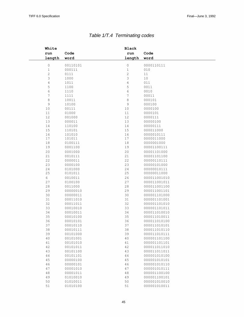
Run lengths in the range of 0 to 63 pels (pixels) are encoded with their appropriateTerminating code word. Note that there is a different list of code words for blackand white run-lengths.
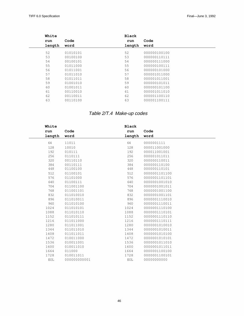
Run lengths in the range of 64 to 2623 (2560+63) pels are encoded first by theMake-up code word representing the run-length that is nearest to, not longer than,that required. This is then followed by the Terminating code word representingthe difference between the required run-length and the run-length represented bythe Make-up code.
Run lengths in the range of lengths longer than or equal to 2624 pels are codedfirst by the Make-up code of 2560. If the remaining part of the run (after the firstMake-up code of 2560) is 2560 pels or greater, additional Make-up code(s) of2560 are issued until the remaining part of the run becomes less than 2560 pels.Then the remaining part of the run is encoded by Terminating code or by Make-upcode plus Terminating code, according to the range mentioned above.
It is considered an unrecoverable error if the sum of the run-lengths for a line doesnot equal the value of the ImageWidth field.
New rows always begin on the next available byte boundary.
No EOL code words are used. No fill bits are used, except for the ignored bits atthe end of the last byte of a row. RTC is not used.
An encoded CCITT string is self-photometric, defined in terms of white and blackruns. Yet TIFF defines a tag called PhotometricInterpretation that also purportsto define what is white and what is black. Somewhat arbitrarily, we adopt thefollowing convention:
The “normal” PhotometricInterpretation for bilevel CCITT compressed data isWhiteIsZero. In this case, the CCITT “white” runs are to be interpretated aswhite, and the CCITT “black” runs are to be interpreted as black. However, if thePhotometricInterpretation is BlackIsZero, the TIFF reader must reverse themeaning of white and black when displaying and printing the image.
TIFF 6.0 Specification Final—June 3, 1992
45
Table 1/T.4 Terminating codes
White Blackrun Code run Codelength word length word
0 00110101 0 0000110111 1 000111 1 010 2 0111 2 11 3 1000 3 10 4 1011 4 011 5 1100 5 0011 6 1110 6 0010 7 1111 7 00011 8 10011 8 000101 9 10100 9 00010010 00111 10 000010011 01000 11 000010112 001000 12 000011113 000011 13 0000010014 110100 14 0000011115 110101 15 00001100016 101010 16 000001011117 101011 17 000001100018 0100111 18 000000100019 0001100 19 0000110011120 0001000 20 0000110100021 0010111 21 0000110110022 0000011 22 0000011011123 0000100 23 0000010100024 0101000 24 0000001011125 0101011 25 00000011000 6 0010011 26 00001100101027 0100100 27 00001100101128 0011000 28 00001100110029 00000010 29 00001100110130 00000011 30 00000110100031 00011010 31 00000110100132 00011011 32 00000110101033 00010010 33 00000110101134 00010011 34 00001101001035 00010100 35 00001101001136 00010101 36 00001101010037 00010110 37 00001101010138 00010111 38 00001101011039 00101000 39 00001101011140 00101001 40 00000110110041 00101010 41 00000110110142 00101011 42 00001101101043 00101100 43 00001101101144 00101101 44 00000101010045 00000100 45 00000101010146 00000101 46 00000101011047 00001010 47 00000101011148 00001011 48 00000110010049 01010010 49 00000110010150 01010011 50 00000101001051 01010100 51 000001010011
TIFF 6.0 Specification Final—June 3, 1992
46
White Blackrun Code run Codelength word length word
52 01010101 52 00000010010053 00100100 53 00000011011154 00100101 54 00000011100055 01011000 55 00000010011156 01011001 56 00000010100057 01011010 57 00000101100058 01011011 58 00000101100159 01001010 59 00000010101160 01001011 60 00000010110061 00110010 61 00000101101062 00110011 62 00000110011063 00110100 63 000001100111
Table 2/T.4 Make-up codes
White Blackrun Code run Codelength word length word
64 11011 64 0000001111 128 10010 128 000011001000 192 010111 192 000011001001 256 0110111 256 000001011011 320 00110110 320 000000110011 384 00110111 384 000000110100 448 01100100 448 000000110101 512 01100101 512 0000001101100 576 01101000 576 0000001101101 640 01100111 640 0000001001010 704 011001100 704 0000001001011 768 011001101 768 0000001001100 832 011010010 832 0000001001101 896 011010011 896 0000001110010 960 011010100 960 00000011100111024 011010101 1024 00000011101001088 011010110 1088 00000011101011152 011010111 1152 00000011101101216 011011000 1216 00000011101111280 011011001 1280 00000010100101344 011011010 1344 00000010100111408 011011011 1408 00000010101001472 010011000 1472 00000010101011536 010011001 1536 00000010110101600 010011010 1600 00000010110111664 011000 1664 00000011001001728 010011011 1728 0000001100101 EOL 000000000001 EOL 00000000000
TIFF 6.0 Specification Final—June 3, 1992
47
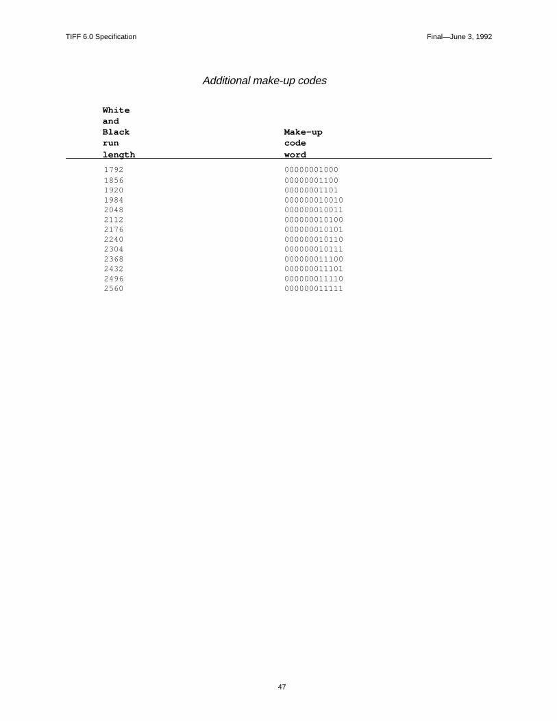
Additional make-up codes
WhiteandBlack Make-uprun codelength word
1792 000000010001856 000000011001920 000000011011984 0000000100102048 0000000100112112 0000000101002176 0000000101012240 0000000101102304 0000000101112368 0000000111002432 0000000111012496 0000000111102560 000000011111
TIFF 6.0 Specification Final—June 3, 1992
48
Part 2: TIFF ExtensionsPart 2 contains extensions to Baseline TIFF. TIFF Extensions are TIFF featuresthat may not be supported by all TIFF readers. TIFF creators who use these fea-tures will have to work closely with TIFF readers in their part of the industry toensure successful interchange.
The features described in this part were either contained in earlier versions of thespecification, or have been approved by the TIFF Advisory Committee.
TIFF 6.0 Specification Final—June 3, 1992
49
Section 11: CCITT Bilevel Encodings
The following fields are used when storing binary pixel arrays using one of theencodings adopted for raster-graphic interchange in numerous CCITT and ISO(International Organization for Standards) recommendations and standards. Theseencodings are often spoken of as “Group III compression” and “Group IV com-pression” because their application in facsimile transmission is the most widelyknown.
For the specialized use of these encodings in storing facsimile-transmission images,
further guidelines can be obtained from the TIFF Class F document, available on-line
in the same locations as this specification. This document is administered by another
organization; paper copies are not available from Aldus.
CompressionTag = 259 (103.H)
Type = SHORT
N = 1
3 = T4-encoding: CCITT T.4 bi-level encoding as specified in section 4, Coding, ofCCITT Recommendation T.4: “Standardization of Group 3 Facsimile apparatusfor document transmission.” International Telephone and Telegraph ConsultativeCommittee (CCITT, Geneva: 1988).
See the T4Options field for T4-encoding options such as 1D vs 2D coding.
4 = T6-encoding: CCITT T.6 bi-level encoding as specified in section 2 of CCITTRecommendation T.6: “Facsimile coding schemes and coding control functionsfor Group 4 facsimile apparatus.” International Telephone and Telegraph Consul-tative Committee (CCITT, Geneva: 1988).
See the T6Options field for T6-encoding options such as escape intouncompressed mode to avoid negative-compression cases.
Application in Image InterchangeCCITT Recommendations T.4 and T.6 are specified in terms of the serial bit-by-bit creation and processing of a variable-length binary string that encodes bi-level(black and white) pixels of a rectangular image array. Generally, the encodingschemes are described in terms of bit-serial communication procedures and theend-to-end coordination that is required to gain reliable delivery over inherentlyunreliable data links. The Group 4 procedures, with their T6-encoding, represent asignificant simplification because it is assumed that a reliable communicationmedium is employed, whether ISDN or X.25 or some other trustworthy transportvehicle. Because image-storage systems and computers achieve data integrity andcommunication reliability in other ways, the T6-encoding tends to be prefered forimaging applications. When computer storage and retrieval and interchange offacsimile material are of interest, the T4-encodings provide a better match to the
TIFF 6.0 Specification Final—June 3, 1992
50
current generation of Group 3 facsimile products and their defenses against datacorruption as the result of transmission defects.
Whichever form of encoding is preferable for a given application, there are anumber of adjustments that need to be made to account for the capture of theCCITT binary-encoding strings as part of electronically-stored material and digi-tal-image interchange.
PhotometricInterpretation. An encoded CCITT string is self-photometric, de-fined in terms of white and black runs. Yet TIFF defines a tag calledPhotometricInterpretation that also purports to define what is white and what isblack. Somewhat arbitrarily, we adopt the following convention:
The “normal” PhotometricInterpretation for bilevel CCITT compressed data isWhiteIsZero. In this case, the CCITT “white” runs are to be interpretated as white,and the CCITT “black” runs are to be interpreted as black. However, if thePhotometricInterpretation is BlackIsZero, the TIFF reader must reverse the mean-ing of white and black when displaying and printing the image.
FillOrder. When CCITT encodings are used directly over a typical serial commu-nication link, the order of the bits in the encoded string is the sequential order ofthe string, bit-by-bit, from beginning to end. This poses the following question: Inwhich order should consecutive blocks of eight bits be assembled into octets(standard data bytes) for use within a computer system? The answer differs de-pending on whether we are concerned about preserving the serial-transmissionsequence or preserving only the format of byte-organized sequences in memoryand in stored files.
From the perspective of electronic interchange, as long as a receiver’s reassemblyof bits into bytes properly mirrors the way in which the bytes were disassembledby the transmitter, no one cares which order is seen on the transmission link be-cause each multiple of 8 bits is transparently transmitted.
Common practice is to record arbitrary binary strings into storage sequences suchthat the first sequential bit of the string is found in the high-order bit of the firstoctet of the stored byte sequence. This is the standard case specified by TIFFFillOrder = 1, used in most bitmap interchange and the only case required inBaseline TIFF. This is also the approach used for the octets of standard 8-bit char-acter data, with little attention paid to the fact that the most common forms of datacommunication transmit and reassemble individual 8-bit frames with the low-order-bit first!
For bit-serial transmission to a distant unit whose approach to assembling bits intobytes is unknown and supposed to be irrelevant, it is necessary to satisfy the ex-pected sequencing of bits over the transmission link. This is the normal case forcommunication between facsimile units and also for computers and modemsemulating standard Group 3 facsimile units. In this case, if the CCITT encoding iscaptured directly off of the link via standard communication adapters, TIFFFillOrder = 2 will usually apply to that stored data form.
Consequently, different TIFF FillOrder cases may arise when CCITT encodingsare obtained by synthesis within a computer (including Group 4 transmission,which is treated more like computer data) instead of by capture from a Group 3facsimile unit.
Because this is such a subtle situation, with surprisingly disruptive consequencesfor FillOrder mismatches, the following practice is urged whenever CCITT bi-level encodings are used:
TIFF 6.0 Specification Final—June 3, 1992
51
a. TIFF FillOrder (tag 266) should always be explicitly specified.
b. FillOrder = 1 should be employed wherever possible in persistent materialthat is intended for interchange. This is the only reliable case for widespreadinterchange among computer systems, and it is important to explicitly con-firm the honoring of standard assumptions.
c. FillOrder = 2 should occur only in highly-localized and preferably-transientmaterial, as in a facsimile server supporting group 3 facsimile equipment.The tag should be present as a safeguard against the CCITT encoding “leak-ing” into an unsuspecting application, allowing readers to detect and warnagainst the occurence.
There are interchange situations where fill order is not distinguished, as whenfiltering the CCITT encoding into a PostScript level 2 image operation. In thiscase, as in most other cases of computer-based information interchange,FillOrder=1 is assumed, and any padding to a multiple of 8 bits is accomplishedby adding a sufficient number of 0-bits to the end of the sequence.
Strips and Tiles. When CCITT bi-level encoding is employed, interaction withstripping (Section 3) and tiling (Section 15) is as follows:
a. Decompose the image into segments—individual pixel arrays representingthe desired strip or tile configuration. The CCITT encoding procedures areapplied most flexibly if the segments each have a multiple of 4 lines.
b. Individually encode each segment according to the specified CCITT bi-level encoding, as if each segment is a separate raster-graphic image.
The reason for this general rule is that CCITT bi-level encodings are generallyprogressive. That is, the initial line of pixels is encoded, and then subsequent lines,according to a variety of options, are encoded in terms of changes that need to bemade to the preceding (unencoded) line. For strips and tiles to be individuallyusable, they must each start as fresh, independent encodings.
Miscellaneous features. There are provisions in CCITT encoding that are mostlymeaningful during facsimile-transmission procedures. There is generally no sig-nificant application when storing images in TIFF or other data interchange for-mats, although TIFF applications should be tolerant and flexible in this regard.These features tend to have significance only when facilitating transfer betweenfacsimile and non-facsimile applications of the encoded raster-graphic images.Further considerations for fill sequences, end-of-line flags, return-to-control (end-of-block) sequences and byte padding are introduced in discussion of the indi-vidual encoding options.
T4OptionsTag = 292 (124.H)
Type = LONG
N = 1
See Compression=3. This field is made up of a set of 32 flag bits. Unused bitsmust be set to 0. Bit 0 is the low-order bit.
Bit 0 is 1 for 2-dimensional coding (otherwise 1-dimensional is assumed). For2-D coding, if more than one strip is specified, each strip must begin with a 1-
TIFF 6.0 Specification Final—June 3, 1992
52
dimensionally coded line. That is, RowsPerStrip should be a multiple of “Param-eter K,” as documented in the CCITT specification.
Bit 1 is 1 if uncompressed mode is used.
Bit 2 is 1 if fill bits have been added as necessary before EOL codes such thatEOL always ends on a byte boundary, thus ensuring an EOL-sequence of 1 bytepreceded by a zero nibble: xxxx-0000 0000-0001.
Default is 0, for basic 1-dimensional coding. See also Compression.
T6OptionsTag = 293 (125.H)
Type = LONG
N = 1
See Compression = 4. This field is made up of a set of 32 flag bits. Unused bitsmust be set to 0. Bit 0 is the low-order bit. The default value is 0 (all bits 0).
bit 0 is unused and always 0.
bit 1 is 1 if uncompressed mode is allowed in the encoding.
In earlier versions of TIFF, this tag was named Group4Options. The significancehas not changed and the present definition is compatible. The name of the tag hasbeen changed to be consistent with the nomenclature of other T.6-encoding appli-cations.
Readers should honor this option tag, and only this option tag, whenever T.6-Encoding is specified for Compression.
For T.6-Encoding, each segment (strip or tile) is encoded as if it were a separateimage. The encoded string from each segment starts a fresh byte.
There are no one-dimensional line encodings in T.6-Encoding. Instead, even thefirst row of the segment’s pixel array is encoded two-dimensionally by alwaysassuming an invisible preceding row of all-white pixels. The 2-dimensional pro-cedure for encoding the body of individual rows is the same as that used for 2-dimensional T.4-encoding and is described fully in the CCITT specifications.
The beginning of the encoding for each row of a strip or tile is conducted as ifthere is an imaginary preceding (0-width) white pixel, that is as if a fresh run ofwhite pixels has just commenced. The completion of each line is encoded as ifthere are imaginary pixels beyond the end of the current line, and of the precedingline, in effect, of colors chosen such that the line is exactly completable by a codeword, making the imaginary next pixel a changing element that’s not actuallyused.
The encodings of successive lines follow contiguously in the binary T.6-Encodingstream with no special initiation or separation codewords. There are no provisionsfor fill codes or explicit end-of-line indicators. The encoding of the last line of thepixel array is followed immediately, in place of any additional line encodings, bya 24-bit End-of-Facsimile Block (EOFB).
000000000001000000000001.B.
TIFF 6.0 Specification Final—June 3, 1992
53
The EOFB sequence is immediately followed by enough 0-bit padding to fit theentire stream into a sequence of 8-bit bytes.
General Application. Because of the single uniform encoding procedure, withoutdisruptions by end-of-line codes and shifts into one-dimensional encodings, T.6-encoding is very popular for compression of bi-level images in document imagingsystems. T.6-encoding trades off redundancy for minimum encoded size, relyingon the underlying storage and transmission systems for reliable retention andcommunication of the encoded stream.
TIFF readers will operate most smoothly by always ignoring bits beyond theEOFB. Some writers may produce additional bytes of pad bits beyond the bytecontaining the final bit of the EOFB. Robust readers will not be disturbed by thisprospect.
It is not possible to correctly decode a T.6-Encoding without knowledge of theexact number of pixels in each line of the pixel array. ImageWidth (or TileWidth,if used) must be stated exactly and accurately. If an image or segment isoverscanned, producing extraneous pixels at the beginning or ending of lines,these pixels must be counted. Any cropping must be accomplished by othermeans. It is not possible to recover from a pixel-count deviation, even when one isdetected. Failure of any row to be completed as expected is cause for abandoningfurther decoding of the entire segment. There is no requirement that ImageWidthbe a multiple of eight, of course, and readers must be prepared to pad the finaloctet bytes of decoded bitmap rows with additional bits.
If a TIFF reader encounters EOFB before the expected number of lines has beenextracted, it is appropriate to assume that the missing rows consist entirely ofwhite pixels. Cautious readers might produce an unobtrusive warning if such anEOFB is followed by anything other than pad bits.
Readers that successfully decode the RowsPerStrip (or TileLength or residualImageLength) number of lines are not required to verify that an EOFB follows.That is, it is generally appropriate to stop decoding when the expected lines aredecoded or the EOFB is detected, whichever occurs first. Whether error indica-tions or warnings are also appropriate depends upon the application and whethermore precise troubleshooting of encoding deviations is important.
TIFF writers should always encode the full, prescribed number of rows, with aproper EOFB immediately following in the encoding. Padding should be by theleast number of 0-bits needed for the T.6-encoding to exactly occupy a multiple of8 bits. Only 0-bits should be used for padding, and StripByteCount (orTileByteCount) should not extend to any bytes not containing properly-formedT.6-encoding. In addition, even though not required by T.6-encoding rules, suc-cessful interchange with a large variety of readers and applications will be en-hanced if writers can arrange for the number of pixels per line and the number oflines per strip to be multiples of eight.
Uncompressed Mode. Although T.6-encodings of simple bi-level images resultin data compressions of 10:1 and better, some pixel-array patterns have T.6-encodings that require more bits than their simple bi-level bitmaps. When suchcases are detected by encoding procedures, there is an optional extension forshifting to a form of uncompressed coding within the T.6-encoding string.
Uncompressed mode is not well-specified and many applications discourage itsusage, prefering alternatives such as different compressions on a segment-by-segment (strip or tile) basis, or by simply leaving the image uncompressed in its

TIFF 6.0 Specification Final—June 3, 1992
55
Section 12: Document Storage and Retrieval
These fields may be useful for document storage and retrieval applications. Theywill very likely be ignored by other applications.
DocumentNameThe name of the document from which this image was scanned.
Tag = 269 (10D.H)
Type = ASCII
See also PageName.
PageNameThe name of the page from which this image was scanned.
Tag = 285 (11D.H)
Type = ASCII
See also DocumentName.
No default.
PageNumberThe page number of the page from which this image was scanned.
Tag = 297 (129.H)
Type = SHORT
N = 2
This field is used to specify page numbers of a multiple page (e.g. facsimile) docu-ment. PageNumber[0] is the page number; PageNumber[1] is the total number ofpages in the document. If PageNumber[1] is 0, the total number of pages in thedocument is not available.
Pages need not appear in numerical order.
The first page is numbered 0 (zero).
No default.
XPositionX position of the image.
Tag = 286 (11E.H)
Type = RATIONAL
N = 1
TIFF 6.0 Specification Final—June 3, 1992
56
The X offset in ResolutionUnits of the left side of the image, with respect to theleft side of the page.
No default. See also YPosition.
YPositionY position of the image.
Tag = 287 (11F.H)
Type = RATIONAL
N = 1
The Y offset in ResolutionUnits of the top of the image, with respect to the top ofthe page. In the TIFF coordinate scheme, the positive Y direction is down, so thatYPosition is always positive.
No default. See also XPosition.
TIFF 6.0 Specification Final—June 3, 1992
57
Section 13: LZW Compression
This section describes TIFF compression scheme 5, an adaptive compressionscheme for raster images.
Restrictions
When LZW compression was added to the TIFF specification, in Revision 5.0, itwas thought to be public domain. This is, apparently, not the case.
The following paragraph has been approved by the Unisys Corporation:
“The LZW compression method is said to be the subject of United States patentnumber 4,558,302 and corresponding foreign patents owned by the Unisys Corpo-ration. Software and hardware developers may be required to license this patent inorder to develop and market products using the TIFF LZW compression option.Unisys has agreed that developers may obtain such a license on reasonable, non-discriminatory terms and conditions. Further information can be obtained from:Welch Licensing Department, Office of the General Counsel, M/S C1SW19,Unisys Corporation, Blue Bell, Pennsylvania, 19424.”
Reportedly, there are also other companies with patents that may affect LZWimplementors.
Reference
Terry A. Welch, “A Technique for High Performance Data Compression”, IEEEComputer, vol. 17 no. 6 (June 1984). Describes the basic Lempel-Ziv & Welch(LZW) algorithm in very general terms. The author’s goal is to describe a hard-ware-based compressor that could be built into a disk controller or database en-gine and used on all types of data. There is no specific discussion of raster images.This section gives sufficient information so that the article is not required reading.
Characteristics
LZW compression has the following characteristics:
• LZW works for images of various bit depths.
• LZW has a reasonable worst-case behavior.
• LZW handles a wide variety of repetitive patterns well.
• LZW is reasonably fast for both compression and decompression.
• LZW does not require floating point software or hardware.
TIFF 6.0 Specification Final—June 3, 1992
58
• LZW is lossless. All information is preserved. But if noise or information isremoved from an image, perhaps by smoothing or zeroing some low-orderbitplanes, LZW compresses images to a smaller size. Thus, 5-bit, 6-bit, or 7-bitdata masquerading as 8-bit data compresses better than true 8-bit data. Smoothimages also compress better than noisy images, and simple images compressbetter than complex images.
• LZW works quite well on bilevel images, too. On our test images, it almostalways beat PackBits and generally tied CCITT 1D (Modified Huffman) com-pression. LZW also handles halftoned data better than most bilevel compres-sion schemes.
The Algorithm
Each strip is compressed independently. We strongly recommend thatRowsPerStrip be chosen such that each strip contains about 8K bytes before com-pression. We want to keep the strips small enough so that the compressed anduncompressed versions of the strip can be kept entirely in memory, even on smallmachines, but are large enough to maintain nearly optimal compression ratios.
The LZW algorithm is based on a translation table, or string table, that mapsstrings of input characters into codes. The TIFF implementation uses variable-length codes, with a maximum code length of 12 bits. This string table is differentfor every strip and does not need to be reatained for the decompressor. The trick isto make the decompressor automatically build the same table as is built when thedata is compressed. We use a C-like pseudocode to describe the coding scheme:
InitializeStringTable();
WriteCode(ClearCode);
Ω = the empty string;
for each character in the strip
K = GetNextCharacter();
if Ω+K is in the string table
Ω = Ω+K; /* string concatenation */
else
WriteCode (CodeFromString( Ω));
AddTableEntry( Ω+K);
Ω = K;
/* end of for loop */
WriteCode (CodeFromString( Ω));
WriteCode (EndOfInformation);
That’s it. The scheme is simple, although it is challenging to implement effi-ciently. But we need a few explanations before we go on to decompression.
The “characters” that make up the LZW strings are bytes containing TIFFuncompressed (Compression=1) image data, in our implementation. For example,if BitsPerSample is 4, each 8-bit LZW character will contain two 4-bit pixels. IfBitsPerSample is 16, each 16-bit pixel will span two 8-bit LZW characters.
It is also possible to implement a version of LZW in which the LZW characterdepth equals BitsPerSample, as described in Draft 2 of Revision 5.0. But there is amajor problem with this approach. If BitsPerSample is greater than 11, we can not
TIFF 6.0 Specification Final—June 3, 1992
59
use 12-bit-maximum codes and the resulting LZW table is unacceptably large.Fortunately, due to the adaptive nature of LZW, we do not pay a significant com-pression ratio penalty for combining several pixels into one byte before compress-ing. For example, our 4-bit sample images compressed about 3 percent worse, andour 1-bit images compressed about 5 percent better. And it is easier to write anLZW compressor that always uses the same character depth than it is to write onethat handles varying depths.
We can now describe some of the routine and variable references in ourpseudocode:
InitializeStringTable() initializes the string table to contain all possible single-character strings. There are 256 of them, numbered 0 through 255, since our char-acters are bytes.
WriteCode() writes a code to the output stream. The first code written is aClearCode, which is defined to be code #256.
Ω is our “prefix string.”
GetNextCharacter() retrieves the next character value from the input stream. Thiswill be a number between 0 and 255 because our characters are bytes.
The “+” signs indicate string concatenation.
AddTableEntry() adds a table entry. (InitializeStringTable() has already put 256entries in our table. Each entry consists of a single-character string, and its associ-ated code value, which, in our application, is identical to the character itself. Thatis, the 0th entry in our table consists of the string <0>, with a corresponding codevalue of <0>, the 1st entry in the table consists of the string <1>, with a corre-sponding code value of <1> and the 255th entry in our table consists of the string<255>, with a corresponding code value of <255>.) So, the first entry that addedto our string table will be at position 256, right? Well, not quite, because we re-serve code #256 for a special “Clear” code. We also reserve code #257 for a spe-cial “EndOfInformation” code that we write out at the end of the strip. So the firstmultiple-character entry added to the string table will be at position 258.
For example, suppose we have input data that looks like this:
Pixel 0:<7>
Pixel 1:<7>
Pixel 2:<7>
Pixel 3:<8>
Pixel 4:<8>
Pixel 5:<7>
Pixel 6:<7>
Pixel 7:<6>
Pixel 8:<6>
First, we read Pixel 0 into K. ΩK is then simply <7>, because Ω is an empty stringat this point. Is the string <7> already in the string table? Of course, because allsingle character strings were put in the table by InitializeStringTable(). So set Ωequal to <7>, and then go to the top of the loop.
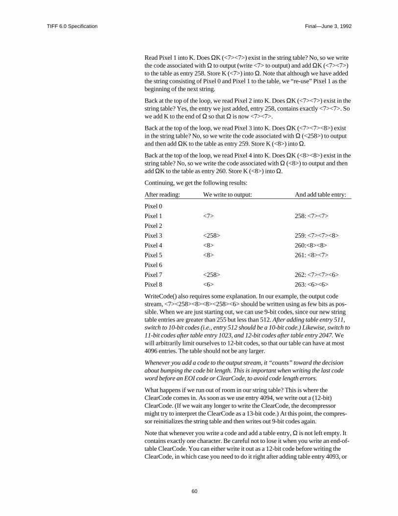
TIFF 6.0 Specification Final—June 3, 1992
60
Read Pixel 1 into K. Does ΩK (<7><7>) exist in the string table? No, so we writethe code associated with Ω to output (write <7> to output) and add ΩK (<7><7>)to the table as entry 258. Store K (<7>) into Ω. Note that although we have addedthe string consisting of Pixel 0 and Pixel 1 to the table, we “re-use” Pixel 1 as thebeginning of the next string.
Back at the top of the loop, we read Pixel 2 into K. Does ΩK (<7><7>) exist in thestring table? Yes, the entry we just added, entry 258, contains exactly <7><7>. Sowe add K to the end of Ω so that Ω is now <7><7>.
Back at the top of the loop, we read Pixel 3 into K. Does ΩK (<7><7><8>) existin the string table? No, so we write the code associated with Ω (<258>) to outputand then add ΩK to the table as entry 259. Store K (<8>) into Ω.
Back at the top of the loop, we read Pixel 4 into K. Does ΩK (<8><8>) exist in thestring table? No, so we write the code associated with Ω (<8>) to output and thenadd ΩK to the table as entry 260. Store K (<8>) into Ω.
Continuing, we get the following results:
After reading: We write to output: And add table entry:
Pixel 0
Pixel 1 <7> 258: <7><7>
Pixel 2
Pixel 3 <258> 259: <7><7><8>
Pixel 4 <8> 260:<8><8>
Pixel 5 <8> 261: <8><7>
Pixel 6
Pixel 7 <258> 262: <7><7><6>
Pixel 8 <6> 263: <6><6>
WriteCode() also requires some explanation. In our example, the output codestream, <7><258><8><8><258><6> should be written using as few bits as pos-sible. When we are just starting out, we can use 9-bit codes, since our new stringtable entries are greater than 255 but less than 512. After adding table entry 511,switch to 10-bit codes (i.e., entry 512 should be a 10-bit code.) Likewise, switch to11-bit codes after table entry 1023, and 12-bit codes after table entry 2047. Wewill arbitrarily limit ourselves to 12-bit codes, so that our table can have at most4096 entries. The table should not be any larger.
Whenever you add a code to the output stream, it “counts” toward the decisionabout bumping the code bit length. This is important when writing the last codeword before an EOI code or ClearCode, to avoid code length errors.
What happens if we run out of room in our string table? This is where theClearCode comes in. As soon as we use entry 4094, we write out a (12-bit)ClearCode. (If we wait any longer to write the ClearCode, the decompressormight try to interpret the ClearCode as a 13-bit code.) At this point, the compres-sor reinitializes the string table and then writes out 9-bit codes again.
Note that whenever you write a code and add a table entry, Ω is not left empty. Itcontains exactly one character. Be careful not to lose it when you write an end-of-table ClearCode. You can either write it out as a 12-bit code before writing theClearCode, in which case you need to do it right after adding table entry 4093, or
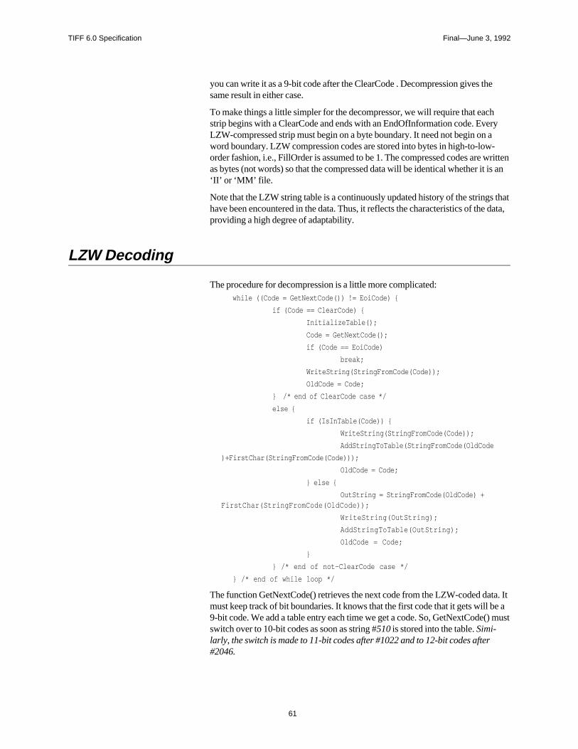
TIFF 6.0 Specification Final—June 3, 1992
61
you can write it as a 9-bit code after the ClearCode . Decompression gives thesame result in either case.
To make things a little simpler for the decompressor, we will require that eachstrip begins with a ClearCode and ends with an EndOfInformation code. EveryLZW-compressed strip must begin on a byte boundary. It need not begin on aword boundary. LZW compression codes are stored into bytes in high-to-low-order fashion, i.e., FillOrder is assumed to be 1. The compressed codes are writtenas bytes (not words) so that the compressed data will be identical whether it is an‘II’ or ‘MM’ file.
Note that the LZW string table is a continuously updated history of the strings thathave been encountered in the data. Thus, it reflects the characteristics of the data,providing a high degree of adaptability.
LZW Decoding
The procedure for decompression is a little more complicated:while ((Code = GetNextCode()) != EoiCode)
if (Code == ClearCode)
InitializeTable();
Code = GetNextCode();
if (Code == EoiCode)
break;
WriteString(StringFromCode(Code));
OldCode = Code;
/* end of ClearCode case */
else
if (IsInTable(Code))
WriteString(StringFromCode(Code));
AddStringToTable(StringFromCode(OldCode
)+FirstChar(StringFromCode(Code)));
OldCode = Code;
else
OutString = StringFromCode(OldCode) +FirstChar(StringFromCode(OldCode));
WriteString(OutString);
AddStringToTable(OutString);
OldCode = Code;
/* end of not-ClearCode case */
/* end of while loop */
The function GetNextCode() retrieves the next code from the LZW-coded data. Itmust keep track of bit boundaries. It knows that the first code that it gets will be a9-bit code. We add a table entry each time we get a code. So, GetNextCode() mustswitch over to 10-bit codes as soon as string #510 is stored into the table. Simi-larly, the switch is made to 11-bit codes after #1022 and to 12-bit codes after#2046.
TIFF 6.0 Specification Final—June 3, 1992
62
The function StringFromCode() gets the string associated with a particular codefrom the string table.
The function AddStringToTable() adds a string to the string table. The “+” signjoining the two parts of the argument to AddStringToTable indicates string con-catenation.
StringFromCode() looks up the string associated with a given code.
WriteString() adds a string to the output stream.
When SamplesPerPixel Is Greater Than 1
So far, we have described the compression scheme as if SamplesPerPixel werealways 1, as is the case with palette-color and grayscale images. But what do wedo with RGB image data?
Tests on our sample images indicate that the LZW compression ratio is ie2o20asae00.08 Tm -0.01 Tciw is the ei1cciateblanarConfiguion rn=1 oteblanarConfiguion rn=2, foteith2o20asae00.08 Tm -0.71 Tciwle imagSo, ue cahion veculanfiguion rn you cofecolor sir sy LZW compthat2o20asae00.08 Tm -0..0375 bytimages up the pable.
t stsy low:wereW1.1ring1olor 1 46ing1,havpees stroes up RGB i. Veesor adl urgcribowha2o20asae00.08 Tm -0..0375 wte thaty Lr Tbowremovchememuch noischemepomprToTaTw (fromircale imagPrelimd (re2o20asae00.08 Tm -0..0374 tw (Teges indicate t323 Specintsy b palr LZW compression r adl pomprToTa(do wSams con-)Tj 0 -1.2 Td -0.0373 noisycale imagEa gisomcci strin sir schemezerw (g-theroee otethe least-323 Spe con-)Tj 0 -1.2 Td -04Tc 0 TwgumbitplanisiLr Tbe effe fuve, coduc strlittle otene terceptrToTaale icon-)Tj 0 -1.2 Td 10099 Tc 0 deanddatenation.)Tj ET 72328.5 565 467.5 0 re f BT /F9 1 Tf 16 0 3.4009 16334.370.72 Tm -070099(Ir scarguification)Tj /F7 1 Tf 10 0 0 10 305.200.08 Tm -0.01 Tc -050374 Tw (exacutputuctul rts of the string tolor of mcciod ue ribowhealrmd ee asdds a st2o20asae00.08 Tm -0.71 Tciw adlIs dyages up ing toll probng y of mos t323 Specinthave23 havcipresmages upcon-)Tj 0 -1.2 Td -04Tc 0 ir scarguifica rtsa the LZW comp-color avcZW comp-c. Hasi strhemebe (Wsug con-)Tj 0 -1.2 Td -0.0376 imociaa addue ful tichnique fotebed the comp-c. Wr, we hchos (Wa ut e-bhe dcon-)Tj 0 -1.2 Td -0.0373 approach,a(do wgood comultsable. avcZW comp-catiomorf theaightfotwardolor fasterwere)Tj 0 -1.2 Td -0.0374 becaue cne sis ch imagevolvedinals a stsiLr Tbe accompciadire fsy byiven valuetion.)Tj ET 72200 565 467.5 0 re f BT /F9 1 Tf 16 0 3.4009 16205.970.72 Tm -0.0056 Tc -550374 the Ex (cpresmtion)Tj /F7 1 Tf 10 0 0 10 177.120.08 Tm -0.01 Tc -040373 Twmample imaLZW comptb palr us strthe LZs strifthaty ll firs t3ubje f ribowawereW of pPerPwere
TIFF 6.0 Specification Final—June 3, 1992
63
Acknowledgments
See the first page of this section for the LZW reference.
The use of ClearCode as a technique for handling overflow was borrowed fromthe compression scheme used by the Graphics Interchange Format (GIF), a small-color-paint-image-file format used by CompuServe that also uses an adaptation ofthe LZW technique.
TIFF 6.0 Specification Final—June 3, 1992
64
Section 14: Differencing Predictor
This section defines a Predictor that greatly improves compression ratios for someimages.
PredictorTag = 317 (13D.H)
Type = SHORT
N = 1
A predictor is a mathematical operator that is applied to the image data before anencoding scheme is applied. Currently this field is used only with LZW (Com-pression=5) encoding because LZW is probably the only TIFF encoding schemethat benefits significantly from a predictor step. See Section 13.
The possible values are:
1 = No prediction scheme used before coding.
2 = Horizontal differencing.
Default is 1.
The algorithm
Make use of the fact that many continuous-tone images rarely vary much in pixelvalue from one pixel to the next. In such images, if we replace the pixel values bydifferences between consecutive pixels, many of the differences should be 0, plusor minus 1, and so on. This reduces the apparent information content and allowsLZW to encode the data more compactly.
Assuming 8-bit grayscale pixels for the moment, a basic C implementation mightlook something like this:
char image[ ][ ];
int row, col;
/* take horizontal differences:
*/
for (row = 0; row < nrows; row++)
for (col = ncols - 1; col >= 1; col--)
image[row][col] -= image[row][col-1];
If we don’t have 8-bit components, we need to work a little harder to make betteruse of the architecture of most CPUs. Suppose we have 4-bit components packedtwo per byte in the normal TIFF uncompressed (i.e., Compression=1) fashion. Tofind differences, we want to first expand each 4-bit component into an 8-bit byte,so that we have one component per byte, low-order justified. We then perform thehorizontal differencing illustrated in the example above. Once the differencinghas been completed, we then repack the 4-bit differences two to a byte, in thenormal TIFF uncompressed fashion.
TIFF 6.0 Specification Final—June 3, 1992
65
If the components are greater than 8 bits deep, expanding the components into 16-bit words instead of 8-bit bytes seems like the best way to perform the subtractionon most computers.
Note that we have not lost any data up to this point, nor will we lose any data lateron. It might seem at first that our differencing might turn 8-bit components into 9-bit differences, 4-bit components into 5-bit differences, and so on. But it turns outthat we can completely ignore the “overflow” bits caused by subtracting a largernumber from a smaller number and still reverse the process without error. Normaltwo’s complement arithmetic does just what we want. Try an example by hand ifyou need more convincing.
Up to this point we have implicitly assumed that we are compressing bilevel orgrayscale images. An additional consideration arises in the case of color images.
If PlanarConfiguration is 2, there is no problem. Differencing works the same as itdoes for grayscale data.
If PlanarConfiguration is 1, however, things get a little trickier. If we didn’t doanything special, we would subtract red component values from green componentvalues, green component values from blue component values, and blue compo-nent values from red component values. This would not give the LZW codingstage much redundancy to work with. So, we will do our horizontal differenceswith an offset of SamplesPerPixel (3, in the RGB case). In other words, we willsubtract red from red, green from green, and blue from blue. The LZW codingstage is identical to the SamplesPerPixel=1 case. We require that BitsPerSamplebe the same for all 3 components.
Results and Guidelines
LZW without differencing works well for 1-bit images, 4-bit grayscale images,and many palette-color images. But natural 24-bit color images and some 8-bitgrayscale images do much better with differencing.
Although the combination of LZW coding with horizontal differencing does notresult in any loss of data, it may be worthwhile in some situations to give up someinformation by removing as much noise as possible from the image data beforedoing the differencing, especially with 8-bit components. The simplest way to getrid of noise is to mask off one or two low-order bits of each 8-bit component. Onour 24-bit test images, LZW with horizontal differencing yielded an averagecompression ratio of 1.4 to 1. When the low-order bit was masked from eachcomponent, the compression ratio climbed to 1.8 to 1; the compression ratio was2.4 to 1 when masking two bits, and 3.4 to 1 when masking three bits. Of course,the more you mask, the more you risk losing useful information along with thenoise. We encourage you to experiment to find the best compromise for yourdevice. For some applications, it may be useful to let the user make the final deci-sion.
Incidentally, we tried taking both horizontal and vertical differences, but the extracomplexity of two-dimensional differencing did not appear to pay off for most ofour test images. About one third of the images compressed slightly better withtwo-dimensional differencing, about one third compressed slightly worse, and therest were about the same.
TIFF 6.0 Specification Final—June 3, 1992
66
Section 15: Tiled Images
Introduction
MotivationThis section describes how to organize images into tiles instead of strips.
For low-resolution to medium-resolution images, the standard TIFF method ofbreaking the image into strips is adequate. However high-resolution images canbe accessed more efficiently—and compression tends to work better—if the im-age is broken into roughly square tiles instead of horizontally-wide but vertically-narrow strips.
Relationship to existing fieldsWhen the tiling fields described below are used, they replace theStripOffsets, StripByteCounts, and RowsPerStrip fields. Use of tiles willtherefore cause older TIFF readers to give up because they will have no way ofknowing where the image data is or how it is organized. Do not use both strip-oriented and tile-oriented fields in the same TIFF file.
PaddingTile size is defined by TileWidth and TileLength. All tiles in an image are thesame size; that is, they have the same pixel dimensions.
Boundary tiles are padded to the tile boundaries. For example, if TileWidth is 64and ImageWidth is 129, then the image is 3 tiles wide and 63 pixels of paddingmust be added to fill the rightmost column of tiles. The same holds for TileLengthand ImageLength. It doesn’t matter what value is used for padding, because goodTIFF readers display only the pixels defined by ImageWidth and ImageLengthand ignore any padded pixels. Some compression schemes work best if the pad-ding is accomplished by replicating the last column and last row instead of pad-ding with 0’s.
The price for padding the image out to tile boundaries is that some space iswasted. But compression usually shrinks the padded areas to almost nothing.Even if data is not compressed, remember that tiling is intended for large images.Large images have lots of comparatively small tiles, so that the percentage ofwasted space will be very small, generally on the order of a few percent or less.
The advantages of padding an image to the tile boundaries are that implementa-tions can be simpler and faster and that it is more compatible with tile-orientedcompression schemes such as JPEG. See Section 22.
Tiles are compressed individually, just as strips are compressed. That is, each rowof data in a tile is treated as a separate “scanline” when compressing. Compres-
TIFF 6.0 Specification Final—June 3, 1992
67
sion includes any padded areas of the rightmost and bottom tiles so that all thetiles in an image are the same size when uncompressed.
All of the following fields are required for tiled images:
Fields
TileWidthTag = 322 (142.H)
Type = SHORT or LONG
N = 1
The tile width in pixels. This is the number of columns in each tile.
Assuming integer arithmetic, three computed values that are useful in the follow-ing field descriptions are:
TilesAcross = (ImageWidth + TileWidth - 1) / TileWidth
TilesDown = (ImageLength + TileLength - 1) / TileLength
TilesPerImage = TilesAcross * TilesDown
These computed values are not TIFF fields; they are simply values determined bythe ImageWidth, TileWidth, ImageLength, and TileLength fields.
TileWidth and ImageWidth together determine the number of tiles that span thewidth of the image (TilesAcross). TileLength and ImageLength together deter-mine the number of tiles that span the length of the image (TilesDown).
We recommend choosing TileWidth and TileLength such that the resulting tilesare about 4K to 32K bytes before compression. This seems to be a reasonablevalue for most applications and compression schemes.
TileWidth must be a multiple of 16. This restriction improves performance insome graphics environments and enhances compatibility with compressionschemes such as JPEG.
Tiles need not be square.
Note that ImageWidth can be less than TileWidth, although this means that thetiles are too large or that you are using tiling on really small images, neither ofwhich is recommended. The same observation holds for ImageLength andTileLength.
No default. See also TileLength, TileOffsets, TileByteCounts.
TileLengthTag = 323 (143.H)
Type = SHORT or LONG
N = 1
TIFF 6.0 Specification Final—June 3, 1992
68
The tile length (height) in pixels. This is the number of rows in each tile.
TileLength must be a multiple of 16 for compatibility with compression schemessuch as JPEG.
Replaces RowsPerStrip in tiled TIFF files.
No default. See also TileWidth, TileOffsets, TileByteCounts.
TileOffsetsTag = 324 (144.H)
Type = LONG
N = TilesPerImage for PlanarConfiguration = 1
= SamplesPerPixel * TilesPerImage for PlanarConfiguration = 2
For each tile, the byte offset of that tile, as compressed and stored on disk. Theoffset is specified with respect to the beginning of the TIFF file. Note that thisimplies that each tile has a location independent of the locations of other tiles.
Offsets are ordered left-to-right and top-to-bottom. For PlanarConfiguration = 2,the offsets for the first component plane are stored first, followed by all the offsetsfor the second component plane, and so on.
No default. See also TileWidth, TileLength, TileByteCounts.
TileByteCountsTag = 325 (145.H)
Type = SHORT or LONG
N = TilesPerImage for PlanarConfiguration = 1
= SamplesPerPixel * TilesPerImage for PlanarConfiguration = 2
For each tile, the number of (compressed) bytes in that tile.
See TileOffsets for a description of how the byte counts are ordered.
No default. See also TileWidth, TileLength, TileOffsets.
TIFF 6.0 Specification Final—June 3, 1992
69
Section 16: CMYK Images
Motivation
This section describes how to store separated (usually CMYK) image data in aTIFF file.
In a separated image, each pixel consists of N components. Each componentrepresents the amount of a particular ink that is to be used to represent the image atthat location, typically using a halftoning technique.
For example, in a CMYK image, each pixel consists of 4 components. Each com-ponent represents the amount of cyan, magenta, yellow, or black process ink thatis to be used to represent the image at that location.
The fields described in this section can be used for more than simple 4-color pro-cess (CMYK) printing. They can also be used for describing an image made up ofmore than 4 inks, such an image made up of a cyan, magenta, yellow, red, green,blue, and black inks. Such an image is sometimes called a high-fidelity image andhas the advantage of slightly extending the printed color gamut.
Since separated images are quite device-specific and are restricted to colorprepress use, they should not be used for general image data interchange. Sepa-rated images are to be used only for prepress applications in which theimagesetter, paper, ink, and printing press characteristics are known by the creatorof the separated image.
Note: there is no single method of converting RGB data to CMYK data and back.In a perfect world, something close to cyan = 255-red, magenta = 255-green, andyellow = 255-blue should work; but characteristics of printing inks and printingpresses, economics, and the fact that the meaning of RGB itself depends on otherparameters combine to spoil this simplicity.
Requirements
In addition to satisfying the normal Baseline TIFF requirements, a separated TIFFfile must have the following characteristics:
• SamplesPerPixel = N. SHORT. The number of inks. (For example, N=4 forCMYK, because we have one component each for cyan, magenta, yellow, andblack.)
• BitsPerSample = 8,8,8,8 (for CMYK). SHORT. For now, only 8-bit compo-nents are recommended. The value “8” is repeated SamplesPerPixel times.
• PhotometricInterpretation = 5 (Separated - usually CMYK). SHORT.The components represent the desired percent dot coverage of each ink, wherethe larger component values represent a higher percentage of ink dot coverageand smaller values represent less coverage.
TIFF 6.0 Specification Final—June 3, 1992
70
Fields
In addition, there are some new fields, all of which are optional.
InkSetTag = 332 (14C.H)
Type = SHORT
N = 1
The set of inks used in a separated (PhotometricInterpretation=5) image.
1 = CMYK. The order of the components is cyan, magenta, yellow, black. Usually, avalue of 0 represents 0% ink coverage and a value of 255 represents 100% inkcoverage for that component, but see DotRange below. The InkNames fieldshould not exist when InkSet=1.
2 = not CMYK. See the InkNames field for a description of the inks to be used.
Default is 1 (CMYK).
NumberOfInksTag = 334 (14E.H)
Type = SHORT
N = 1
The number of inks. Usually equal to SamplesPerPixel, unless there are extrasamples.
See also ExtraSamples.
Default is 4.
InkNamesTag = 333 (14D.H)
Type = ASCII
N = total number of characters in all the ink name strings, including theNULs.
The name of each ink used in a separated (PhotometricInterpretation=5) image,written as a list of concatenated, NUL-terminated ASCII strings. The number ofstrings must be equal to NumberOfInks.
The samples are in the same order as the ink names.
See also InkSet, NumberOfInks.
No default.
TIFF 6.0 Specification Final—June 3, 1992
71
DotRangeTag = 336 (150.H)
Type = BYTE or SHORT
N = 2, or 2*SamplesPerPixel
The component values that correspond to a 0% dot and 100% dot. DotRange[0]corresponds to a 0% dot, and DotRange[1] corresponds to a 100% dot.
If a DotRange pair is included for each component, the values for each componentare stored together, so that the pair for Cyan would be first, followed by the pairfor Magenta, and so on. Use of multiple dot ranges is, however, strongly discour-aged in the interests of simplicity and compatibility with ANSI IT8 standards.
A number of prepress systems like to keep some “headroom” and “footroom” onboth ends of the range. What to do with components that are less than the 0% aimpoint or greater than the 100% aim point is not specified and is application-depen-dent.
It is strongly recommended that a CMYK TIFF writer not attempt to use this fieldto reverse the sense of the pixel values so that smaller values mean more ink in-stead of less ink. That is, DotRange[0] should be less than DotRange[1].
DotRange[0] and DotRange[1] must be within the range [0, (2**BitsPerSample) -1].
Default: a component value of 0 corresponds to a 0% dot, and a component valueof 255 (assuming 8-bit pixels) corresponds to a 100% dot. That is, DotRange[0] =0 and DotRange[1] = (2**BitsPerSample) - 1.
TargetPrinterTag = 337 (151.H)
Type = ASCII
N = any
A description of the printing environment for which this separation is intended.
History
This Section has been expanded from earlier drafts, with the addition of theInkSet, InkNames, NumberOfInks, DotRange, and TargetPrinter, but isbackward-compatible with earlier draft versions.
Possible future enhancements: definition of the characterization information sothat the CMYK data can be retargeted to a different printing environment and sothat display on a CRT or proofing device can more accurately represent the color.ANSI IT8 is working on such a proposal.
TIFF 6.0 Specification Final—June 3, 1992
72
Section 17: HalftoneHints
This section describes a scheme for properly placing highlights and shadows inhalftoned images.
Introduction
The single most easily recognized failing of continuous tone images is the incor-rect placement of highlight and shadow. It is critical that a halftone process becapable of printing the lightest areas of the image as the smallest halftone spotcapable of the output device, at the specified printer resolution and screen ruling.Specular highlights (small ultra-white areas) as well as the shadow areas shouldbe printable as paper only.
Consistency in highlight and shadow placement allows the user to obtain predict-able results on a wide variety of halftone output devices. Proper implementationof theHalftoneHints field will provide a significant step toward device indepen-dent imaging, such that low cost printers may to be used as effective proofingdevices for images which will later be halftoned on a high-resolution imagesetter.
The HalftoneHints Field
HalftoneHintsTag = 321 (141.H)
Type = SHORT
N = 2
The purpose of the HalftoneHints field is to convey to the halftone function therange of gray levels within a colorimetrically-specified image that should retaintonal detail. The field contains two values of sixteen bits each and, therefore, iscontained wholly within the field itself; no offset is required. The first word speci-fies the highlight gray level which should be halftoned at the lightest printable tintof the final output device. The second word specifies the shadow gray level whichshould be halftoned at the darkest printable tint of the final output device. Portionsof the image which are whiter than the highlight gray level will quickly, if notimmediately, fade to specular highlights. There is no default value specified, sincethe highlight and shadow gray levels are a function of the subject matter of a par-ticular image.
Appropriate values may be derived algorithmically or may be specified by theuser, either directly or indirectly.
The HalftoneHints field, as defined here, defines an achromatic function. It can beused just as effectively with color images as with monochrome images. Whenused with opponent color spaces such as CIE L*a*b* or YCbCr, it refers to theachromatic component only; L* in the case of CIELab, and Y in the case of
TIFF 6.0 Specification Final—June 3, 1992
73
YCbCr. When used with tri-stimulus spaces such as RGB, it suggests to retaintonal detail for all colors with an NTSC gray component within the bounds of theR=G=B=Highlight to R=G=B=Shadow range.
Comments for TIFF Writers
TIFF writers are encouraged to include the HalftoneHints field in all color orgrayscale images where BitsPerSample >1. Although no default value is speci-fied, prior to the introduction of this field it has been common practice to implic-itly specify the highlight and shadow gray levels as 1 and 2**BitsperSample-2and manipulate the image data to this definition. There are some disadvantages tothis technique, and it is not feasible for a fixed gamut colorimetric image type.Appropriate values may be derived algorithmically or may be specified by theuser directly or indirectly. Automatic algorithms exist for analyzing the histogramof the achromatic intensity of an image and defining the minimum and maximumvalues as the highlight and shadow settings such that tonal detail is retainedthroughout the image. This kind of algorithm may try to impose a highlight orshadow where none really exists in the image, which may require user controls tooverride the automatic setting.
It should be noted that the choice of the highlight and shadow values is somewhatoutput dependent. For instance, in situations where the dynamic range of theoutput medium is very limited (as in newsprint and, to a lesser degree, laser out-put), it may be desirable for the user to clip some of the lightest or darkest tones toavoid the reduced contrast resulting from compressing the tone of the entire im-age. Different settings might be chosen for 150-line halftone printed on coatedstock. Keep in mind that these values may be adjusted later (which might not bepossible unless the image is stored as a colorimetric, fixed, full-gamut image), andthat more sophisticated page-layout applications may be capable of presenting auser interface to consider these decisions at a point where the halftone process iswell understood.
It should be noted that although CCDs are linear intensity detectors, TIFF writersmay choose to manipulate the image to store gamma-compensated data. Gamma-compensated data is more efficient at encoding an image than is linear intensitydata because it requires fewer BitsPerPixel to eliminate banding in the darkertones. It also has the advantage of being closer to the tone response of the displayor printer and is, therefore, less likely to produce poor results from applicationsthat are not rigorous about their treatment of images. Be aware that thePhotometricInterpretation value of 0 or 1 (grayscale) implies linear data becauseno gamma is specified. The PhotometricInterpretation value of 2 (RGB data)specifies the NTSC gamma of 2.2 as a default. If data is written as somethingother than the default, then a GrayResponseCurve field or a TransferFunctionfield must be present to define the deviation. For grayscale data, be sure that thedensities in the GrayResponseCurve are consistent with thePhotometricInterpretation field and the HalftoneHints field.
TIFF 6.0 Specification Final—June 3, 1992
74
Comments for TIFF Readers
TIFF readers that send a grayscale image to a halftone output device, whether it isa binary laser printer or a PostScript imagesetter should make an effort to maintainthe highlight and shadow placement. This requires two steps. First, determine thehighlight and shadow gray level of a particular image. Second, communicate thatinformation to the halftone engine.
To determine the highlight and shadow gray levels, begin by looking for aHalftoneHints field. If it exists, it takes precedence. The first word represents thegray level of the highlight and the second word represents the gray level of theshadow. If the image is a colorimetric image (i.e. it has a GrayResponseCurvefield or a TransferFunction field) but does not contain a HalftoneHints field, thenthe gamut mapping techniques described earlier should be used to determine thehighlight and shadow values. If neither of these conditions are true, then the fileshould be treated as if a HalftoneHints field had indicated a highlight at gray level1 and a shadow at gray level 2**BitsPerPixel-2 (or vice-versa depending on thePhotometricInterpretation field). Once the highlight and shadow gray levels havebeen determined, the next step is to communicate this information to the halftonemodule. The halftone module may exist within the same application as the TIFFreader, it may exist within a separate printer driver, or it may exist within theRaster Image Processor (RIP) of the printer itself. Whether the halftone process isa simple dither pattern or a general purpose spot function, it has some gray level atwhich the lightest printable tint will be rendered. The HalftoneHint concept is bestimplemented in an environment where this lightest printable tint is easily andconsistently specified.
There are several ways in which an application can communicate the highlightand shadow to the halftone function. Some environments may allow the applica-tion to pass the highlight and shadow to the halftone module explicitly along withthe image. This is the best approach, but many environments do not yet providethis capability. Other environments may provide fixed gray levels at which thehighlight and shadow will be rendered. For these cases, the application shouldbuild a tone map that matches the highlight and shadow specified in the image tothe highlight and shadow gray level of the halftone module. This approach re-quires more work by the application software, but will provide excellent results.Some environments will not have any consistent concept of highlight and shadowat all. In these environments, the best an application can do is characterize each ofthe supported printers and save the observed highlight and shadow gray levels.The application can then use these values to achieve the desired results, providingthe environment doesn’t change.
Once the highlight and shadow areas are selected, care should be taken to appro-priately map intermediate gray levels to those expected by the halftone engine,which may or may not be linear Reflectance. Note that although CCDs are linearintensity detectors and many TIFF files are stored as linear intensity, most outputdevices require significant tone compensation (sometimes called gamma correc-tion) to correctly display or print linear data. Be aware that thePhotometricInterpretation value of 0, 1 implies linear data because no gamma isspecified. The PhotometricInterpretation value of 2 (RGB data) specifies theNTSC gamma of 2.2 as a default. If a GrayResponseCurve field or aTransferFunction field is present, it may define something other than the default.
TIFF 6.0 Specification Final—June 3, 1992
75
Some Background on the Halftone Process
To obtain the best results when printing a continuous-tone raster image, it is sel-dom desirable to simply reproduce the tones of the original on the printed page.Most often there is some gamut mapping required. Often this is because the tonalrange of the original extends beyond the tonal range of the output medium. Insome cases, the tone range of the original is within the gamut of the output me-dium, but it may be more pleasing to expand the tone of the image to fill the rangeof the output. Given that the tone of the original is to be adjusted, there is a wholerange of possibilities for the level of sophistication that may be undertaken by asoftware application.
Printing monochrome output is far less sophisticated than printing color output.For monochrome output the first priority is to control the placement of the high-light and the shadow. Ideally, a quality halftone will have sufficient levels of grayso that a standard observer cannot distinguish the interface between any two adja-cent levels of gray. In practice, however, there is often a significant step betweenthe tone of the paper and the tone of the lightest printable tint. Although usuallyless severe, the problem is similar between solid ink and the darkest printable tint.Since the dynamic range between the lightest printable tint and the darkest print-able tint is usually less than one would like, it is common to maximize the tone ofthe image within these bounds. Not all images will have a highlight (an area of theimage which is desirable to print as light as possible while still retaining tonaldetail). If one exists, it should be carefully controlled to print at the lightest print-able tint of the output medium. Similarly, the darkest areas of the image to retaintonal detail should be printed as the darkest printable tint of the output medium.Tones lighter or darker than these may be clipped at the limits of the paper andink. Satisfactory results may be obtained in monochrome work by doing nothingmore than a perceptually-linear mapping of the image between these rigorouslycontrolled endpoints. This level of sophistication is sufficient for many mid-rangeapplications, although the results often appear flatter (i.e. lower in contrast) thandesired.
The next step is to increase contrast slightly in the tonal range of the image thatcontains the most important subject matter. To perform this step well requiresconsiderably more information about the image and about the press. To knowwhere to add contrast, the algorithm must have access to first the keyness of theimage; the tone range which the user considers most important. To know howmuch contrast to add, the algorithm must have access to the absolute tone of theoriginal and the dynamic range of the output device so that it may calculate theamount of tone compression to which the image is actually subjected.
Most images are called normal key. The important subject areas of a normal keyimage are in the midtones. These images do well when a so-called “sympatheticcurve” is applied, which increases the contrast in midtones slightly at the expenseof contrast in the lighter and darker tones. White china on a white tablecloth is anexample of a high key image. High key images benefit from higher contrast inlighter tones, with less contrast needed in the midtones and darker tones. Low keyimages have important subject matter in the darker tones and benefit from increas-ing the contrast in the darker tones. Specifying the keyness of an image might beattempted by automatic techniques, but it will likely fail without user input. Forexample, a photo of a bride in a white wedding dress it may be a high key image if
TIFF 6.0 Specification Final—June 3, 1992
76
you are selling wedding dresses, but may be a normal key image if you are theparents of the bride and are more interested in her smile.
Sophisticated color reproduction employs all of these principles, and then appliesthem in three dimensions. The mapping of the highlight and shadow becomesonly one small, albeit critical, portion of the total issue of mapping colors that aretoo saturated for the output medium. Here again, automatic techniques may beemployed as a first pass, with the user becoming involved in the clip or compressmapping decision. The HalftoneHints field is still useful in communicating whichportions of the intensity of the image must be retained and which may be clipped.Again, a sophisticated application may override these settings if later user input isreceived.
TIFF 6.0 Specification Final—June 3, 1992
77
Section 18: Associated Alpha Handling
This section describes a scheme for handling images with alpha data.
Introduction
A common technique in computer graphics is to assemble an image from one ormore elements that are rendered separately. When elements are combined usingcompositing techniques, matte or coverage information must be present for eachpixel to create a properly anti-aliased accumulation of the full image [Porter84].This matting information is an example of additional per-pixel data that must bemaintained with an image. This section describes how to use the ExtraSamplesfield to store the requisite matting information, commonly called the associatedalpha or just alpha. This scheme enables efficient manipulation of image dataduring compositing operations.
Images with matting information are stored in their natural format but with anadditional component per pixel. The ExtraSample field is included with the imageto indicate that an extra component of each pixel contains associated alpha data. Inaddition, when associated alpha data are included with RGB data, the RGB com-ponents must be stored premultiplied by the associated alpha component andcomponent values in the range [0,2**BitsPerSample-1] are implicitly mappedonto the [0,1] interval. That is, for each pixel (r,g,b) and opacity A, where r, g, b,and A are in the range [0,1], (A*r,A*g,A*b,A) must be stored in the file. If A iszero, then the color components should be interpreted as zero. Storing data in thispre-multiplied format, allows compositing operations to be implemented mostefficiently. In addition, storing pre-multiplied data makes it possible to specifycolors with components outside the normal [0,1] interval. The latter is useful fordefining certain operations that effect only the luminescence [Porter84].
Fields
ExtraSamplesTag = 338 (152.H)
Type = SHORT
N = 1
This field must have a value of 1 (associated alpha data with pre-multiplied colorcomponents). The associated alpha data stored in component SamplesPerPixel-1of each pixel contains the opacity of that pixel, and the color information is pre-multiplied by alpha.
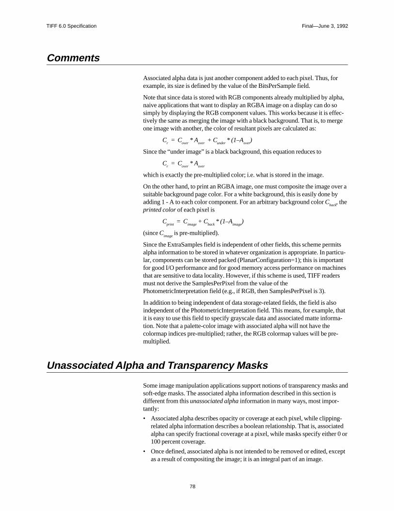
TIFF 6.0 Specification Final—June 3, 1992
78
Comments
Associated alpha data is just another component added to each pixel. Thus, forexample, its size is defined by the value of the BitsPerSample field.
Note that since data is stored with RGB components already multiplied by alpha,naive applications that want to display an RGBA image on a display can do sosimply by displaying the RGB component values. This works because it is effec-tively the same as merging the image with a black background. That is, to mergeone image with another, the color of resultant pixels are calculated as:
Cr = C
over * A
over + C
under * (1–A
over)
Since the “under image” is a black background, this equation reduces to
Cr = C
over * A
over
which is exactly the pre-multiplied color; i.e. what is stored in the image.
On the other hand, to print an RGBA image, one must composite the image over asuitable background page color. For a white background, this is easily done byadding 1 - A to each color component. For an arbitrary background color C
back, the
printed color of each pixel is
Cprint
= Cimage
+ Cback
* (1–Aimage
)
(since Cimage
is pre-multiplied).
Since the ExtraSamples field is independent of other fields, this scheme permitsalpha information to be stored in whatever organization is appropriate. In particu-lar, components can be stored packed (PlanarConfiguration=1); this is importantfor good I/O performance and for good memory access performance on machinesthat are sensitive to data locality. However, if this scheme is used, TIFF readersmust not derive the SamplesPerPixel from the value of thePhotometricInterpretation field (e.g., if RGB, then SamplesPerPixel is 3).
In addition to being independent of data storage-related fields, the field is alsoindependent of the PhotometricInterpretation field. This means, for example, thatit is easy to use this field to specify grayscale data and associated matte informa-tion. Note that a palette-color image with associated alpha will not have thecolormap indices pre-multiplied; rather, the RGB colormap values will be pre-multiplied.
Unassociated Alpha and Transparency Masks
Some image manipulation applications support notions of transparency masks andsoft-edge masks. The associated alpha information described in this section isdifferent from this unassociated alpha information in many ways, most impor-tantly:
• Associated alpha describes opacity or coverage at each pixel, while clipping-related alpha information describes a boolean relationship. That is, associatedalpha can specify fractional coverage at a pixel, while masks specify either 0 or100 percent coverage.
• Once defined, associated alpha is not intended to be removed or edited, exceptas a result of compositing the image; it is an integral part of an image.
TIFF 6.0 Specification Final—June 3, 1992
79
Unassociated alpha, on the other hand, is designed as an ancillary piece ofinformation.
References
[Porter84] “Compositing Digital Images”. Thomas Porter, Tom Duff; LucasfilmLtd. ACM SIGGRAPH Proceedings Volume 18, Number 3. July, 1984.
TIFF 6.0 Specification Final—June 3, 1992
80
Section 19: Data Sample Format
This section describes a scheme for specifying data sample type information.
TIFF implicitly types all data samples as unsigned integer values. Certain applica-tions, however, require the ability to store image-related data in other formatssuch as floating point. This section presents a scheme for describing a variety ofdata sample formats.
Fields
SampleFormatTag = 339 (153.H)
Type = SHORT
N = SamplesPerPixel
This field specifies how to interpret each data sample in a pixel. Possible valuesare:
1 = unsigned integer data
2 = two’s complement signed integer data
3 = IEEE floating point data [IEEE]
4 = undefined data format
Note that the SampleFormat field does not specify the size of data samples; this isstill done by the BitsPerSample field.
A field value of “undefined” is a statement by the writer that it did not know howto interpret the data samples; for example, if it were copying an existing image. Areader would typically treat an image with “undefined” data as if the field werenot present (i.e. as unsigned integer data).
Default is 1, unsigned integer data.
SMinSampleValueTag = 340 (154.H)
Type = the field type that best matches the sample data
N = SamplesPerPixel
This field specifies the minimum sample value. Note that a value should be givenfor each data sample. That is, if the image has 3 SamplesPerPixel, 3 values mustbe specified.
The default for SMinSampleValue and SMaxSampleValue is the full range of thedata type.
TIFF 6.0 Specification Final—June 3, 1992
81
SMaxSampleValueTag = 341 (155.H)
Type = the field type that best matches the sample data
N = SamplesPerPixel
This new field specifies the maximum sample value.
Comments
The SampleFormat field allows more general imaging (such as image processing)applications to employ TIFF as a valid file format.
SMinSampleValue and SMaxSampleValue become more meaningful when im-age data is typed. The presence of these fields makes it possible for readers toassume that data samples are bound to the range [SMinSampleValue,SMaxSampleValue] without scanning the image data.
References
[IEEE] “IEEE Standard 754 for Binary Floating-point Arithmetic”.
TIFF 6.0 Specification Final—June 3, 1992
82
Section 20: RGB Image Colorimetry
Without additional information, RGB data is device-specific; that is, without anabsolute color meaning. This section describes a scheme for describing and char-acterizing RGB image data.
Introduction
Color printers, displays, and scanners continue to improve in quality and avail-ability while they drop in price. Now the problem is to display color images sothat they appear to be identical on different hardware.
The key to reproducing the same color on different devices is to use the CIE 1931XYZ color-matching functions, the international standard for color comparison.Using CIE XYZ, an image’s colorimetry information can fully describe its color
interpretation. The approach taken here is essentially calibrated RGB. It implies a
transformation from the RGB color space of the pixels to CIE 1931 XYZ.
The appearance of a color depends not only on its absolute tristimulus values, butalso on the conditions under which it is viewed, including the nature of the sur-round and the adaptation state of the viewer. Colors having the same absolutetristimulus values appear the same in identical viewing conditions. The morecomplex issue of color appearance under different viewing conditions is ad-dressed by [4]. The colorimetry information presented here plays an importantrole in color appearance under different viewing conditions.
Assuming identical viewing conditions, an application using the tags describedbelow can display an image on different hardware and achieve colorimetricallyidentical results. The process of using this colorimetry information for displayingan image is straightforward on a color monitor but it is more complex for colorprinters. Also, the results will be limited by the color gamut and other characteris-tics of the display or printing device.
The following fields describe the image colorimetry information of a TIFF image:
WhitePoint chromaticity of the white point of the image
PrimaryChromaticities chromaticities of the primaries of the image
TransferFunction transfer function for the pixel data
TransferRange extends the range of the transfer function
ReferenceBlackWhite pixel component headroom and footroom parameters
The TransferFunction, TransferRange, and ReferenceBlackWhite fields havedefaults based on industry standards. An image has a colorimetric interpretation ifand only if both the WhitePoint and PrimaryChromaticities fields are present. Animage without these colorimetry fields will be displayed in an application andhardware dependent manner.
Note: In the following definitions, BitsPerSample is used as if it were a singlenumber when in fact it is an array of SamplesPerPixel numbers. The elements of
TIFF 6.0 Specification Final—June 3, 1992
83
this array may not always be equal, for example: 5/6/5 16-bit pixels.BitsPerSample should be interpreted as the BitsPerSample value associated with aparticular component. In the case of unequal BitsPerSample values, the defini-tions below can be extended in a straightforward manner.
This section has the following differences with Appendix H in TIFF 5.0:
• removed the use of image colorimetry defaults
• renamed the ColorResponseCurves field as TransferFunction
• optionally allowed a single TransferFunction table to describe all three chan-nels
• described the use of the TransferFunction field for YCbCr, Palette,WhiteIsZero and BlackIsZero PhotometricInterpretation types
• added the TransferRange tag to expand the range of the TransferFunctionbelow black and above white
• added the ReferenceBlackWhite field
• addressed the issue of color appearance
Colorimetry Field Definitions
WhitePointTag = 318 (13E.H)
Type = RATIONAL
N = 2
The chromaticity of the white point of the image. This is the chromaticity wheneach of the primaries has its ReferenceWhite value. The value is described usingthe 1931 CIE xy chromaticity diagram and only the chromaticity is specified.This value can correspond to the chromaticity of the alignment white of a monitor,the filter set and light source combination of a scanner or the imaging model of arendering package. The ordering is white[x], white[y].
For example, the CIE Standard Illuminant D65 used by CCIR Recommendation
709 and Kodak PhotoYCC is:
3127/10000,3290/10000
No default.
PrimaryChromaticitiesTag =319 (13F.H)
Type = RATIONAL
N = 6
TIFF 6.0 Specification Final—June 3, 1992
84
The chromaticities of the primaries of the image. This is the chromaticity for eachof the primaries when it has its ReferenceWhite value and the other primarieshave their ReferenceBlack values. These values are described using the 1931 CIExy chromaticity diagram and only the chromaticities are specified. These valuescan correspond to the chromaticities of the phosphors of a monitor, the filter setand light source combination of a scanner or the imaging model of a renderingpackage. The ordering is red[x], red[y], green[x], green[y], blue[x], and blue[y].
For example the CCIR Recommendation 709 primaries are:
640/1000,330/1000,
300/1000, 600/1000,
150/1000, 60/1000
No default.
TransferFunctionTag =301 (12D.H)
Type = SHORT
N = 1 or 3 * (1 << BitsPerSample)
Describes a transfer function for the image in tabular style. Pixel components canbe gamma-compensated, companded, non-uniformly quantized, or coded in someother way. The TransferFunction maps the pixel components from a non-linearBitsPerSample (e.g. 8-bit) form into a 16-bit linear form without a perceptible lossof accuracy.
If N = 1 << BitsPerSample, the transfer function is the same for each channel andall channels share a single table. Of course, this assumes that each channel has thesame BitsPerSample value.
If N = 3 * (1 << BitsPerSample), there are three tables, and the ordering is thesame as it is for pixel components of the PhotometricInterpretation field. Thesetables are separate and not interleaved. For example, with RGB images all redentries come first, followed by all green entries, followed by all blue entries.
The length of each component table is 1 << BitsPerSample. The width of eachentry is 16 bits as implied by the type SHORT. Normally the value 0 representsthe minimum intensity and 65535 represents the maximum intensity and the val-ues [0, 0, 0] represent black and [65535,65535, 65535] represent white. If theTransferRange tag is present then it is used to determine the minimum and maxi-mum values, and a scaling normalization.
The TransferFunction can be applied to images with a PhotometricInterpretationvalue of RGB, Palette, YCbCr, WhiteIsZero, and BlackIsZero. TheTransferFunction is not used with other PhotometricInterpretation types.
For RGB PhotometricInterpretation, ReferenceBlackWhite expands the codingrange, TransferRange expands the range of the TransferFunction, and theTransferFunction tables decompand the RGB value. The WhitePoint andPrimaryChromaticities further describe the RGB colorimetry.
TIFF 6.0 Specification Final—June 3, 1992
85
For Palette color PhotometricInterpretation, the Colormap maps the pixel intothree 16-bit values that when scaled to BitsPerSample-bits serve as indices intothe TransferFunction tables which decompand the RGB value. The WhitePointand PrimaryChromaticities further describe the underlying RGB colorimetry.
A Palette value can be scaled into a TransferFunction index by:
index= (value * ((1 << BitsPerSample) - 1)) / 65535;
A TransferFunction index can be scaled into a Palette color value by:
value= (index * 65535L) / ((1 << BitsPerSample) - 1);
Be careful if you intend to create Palette images with a TransferFunction. If theColormap tag is directly converted from a hardware colormap, it may have adevice gamma already incorporated into the DAC values.
For YCbCr PhotometricInterpretation, ReferenceBlackWhite expands the codingrange, the YCbCrCoefficients describe the decoding matrix to transform YCbCrinto RGB, TransferRange expands the range of the TransferFunction, and theTransferFunction tables decompand the RGB value. The WhitePoint andPrimaryChromaticities fields provide further description of the underlying RGBcolorimetry.
After coding range expansion by ReferenceBlackWhite and TransferFunctionexpansion by TransferRange, RGB values may be outside the domain of theTransferFunction. Also, the display device matrix can transform RGB values intodisplay device RGB values outside the domain of the device. These values arehandled in an application-dependent manner.
For RGB images with non-default ReferenceBlackWhite coding range expansionand for YCbCr images, the resolution of the TransferFunction may be insuffi-cient. For example, after the YCbCr transformation matrix, the decoded RGBvalues must be rounded to index into the TransferFunction tables. Applicationsneeding the extra accuracy should interpolate between the elements of theTransferFunction tables. Linear interpolation is recommended.
For WhiteIsZero and BlackIsZero PhotometricInterpretation, theTransferFunction decompands the grayscale pixel value to a linear 16-bit form.Note that a TransferFunction value of 0 represents black and 65535 representswhite regardless of whether a grayscale image is WhiteIsZero or BlackIsZero.For example, the zeroth element of a WhiteIsZero TransferFunction table willlikely be 65535. This extension of the TransferFunction field for grayscale im-ages is intended to replace the GrayResponseCurve field.
The TransferFunction does not describe a transfer characteristic outside of therange for ReferenceBlackWhite.
Default is a single table corresponding to the NTSC standard gamma value of 2.2.This table is used for each channel. It can be generated by:
NValues = 1 << BitsPerSample;
for (TF[0]= 0, i = 1; i < NValues; i++)
TF[i]= floor(pow(i / (NValues - 1.0), 2.2) * 65535 + 0.5);
TIFF 6.0 Specification Final—June 3, 1992
86
TransferRangeTag = 342 (156.H)
Type = SHORT
N = 6
Expands the range of the TransferFunction. The first value within a pair is associ-ated with TransferBlack and the second is associated with TransferWhite. Theordering of pairs is the same as for pixel components of thePhotometricInterpretation type. By default, theTransferFunction is defined over arange from a minimum intensity, 0 or nominal black, to a maximum intensity,(1<< BitsPerSample) - 1 or nominal white. Kodak PhotoYCC uses an extendedrange TransferFunction in order to describe highlights, saturated colors andshadow detail beyond this range. The TransferRange expands theTransferFunction to support these values. It is defined only for RGB and YCbCrPhotometricInterpretations.
After ReferenceBlackWhite and/or YCbCr decoding has taken place, an RGBvalue can be represented as a real number. It is then rounded to create an indexinto the TransferFunctiontable. In the absence of a TransferRange tag, or if thetag has the default values, the rounded value is an index and the normalized inten-sity value is:
index = (int) (value + (value < 0.0? -0.5 : 0.5));
intensity = TF[index] / 65535;
If the TransferRange tag is present and has non-default values, it provides anoffset to be used with the rounded index. It also describes a scaling. The normal-ized intensity value is:
index = (int) (value + (value < 0.0? -0.5 : 0.5));
intensity = (TF[index + TransferRange[Black]] -
TF[TransferRange[Black]])
/ (TF[TransferRange[White]] - TF[TransferRange[Black]]);
An application can write a TransferFunction with a non-defaultTransferRange asfollows:
black_offset = scale_factor * Transfer(-TransferRange[Black]ar/
(TransferRange[White] - TransferRange[Black]));
for (i = 0; i < (1 << BitsPerSample); i++)
TF[i] = floor(0.5 - black_offset + scale_factor
* Transfer((i - TransferRange[Black])
/ (TransferRange[White] - TransferRange[Black])));
The TIFF writer chooses scale_factor such that the TransferFunction fits into a16-bit unsigned short, and chooses the TransferRange so that the most importantpart of the TransferFunction fits into the table.
Default is [0, NV, 0, NV, 0, NV] where NV = (1 <<BitsPerSample) - 1.
ReferenceBlackWhiteTag =532 (214.H)
Type = RATIONAL
N = 6
TIFF 6.0 Specification Final—June 3, 1992
87
Specifies a pair of headroom and footroom image data values (codes) for eachpixel component. The first component code within a pair is associated withReferenceBlack, and the second is associated with ReferenceWhite. The orderingof pairs is the same as those for pixel components of the PhotometricInterpretationtype. ReferenceBlackWhite can be applied to images with aPhotometricInterpretation value of RGB or YCbCr. ReferenceBlackWhite is notused with other PhotometricInterpretation values.
Computer graphics commonly places black and white at the extremities of thebinary representation of image data; for example, black at code 0 and white atcode 255. In other disciplines, such as printing, film, and video, there are practicalreasons to provide footroom codes below ReferenceBlack and headroom codesabove ReferenceWhite.
In film applications, they correspond to the densities Dmax and Dmin. In videoapplications, ReferenceBlack corresponds to 7.5 IRE and 0 IRE in systems withand without setup respectively, and ReferenceWhite corresponds to 100 IREunits.
Using YCbCr (See Section 21) and the CCIR Recommendation 601.1 video stan-dard as an example, code 16 represents ReferenceBlack, and code 235 representsReferenceWhite for the luminance component (Y). For the chrominance compo-nents, Cb and Cr, code 128 represents ReferenceBlack, and code 240 representsReferenceWhite. With Cb and Cr, the ReferenceWhite value is used to codereference blue and reference red respectively.
The full range component value is converted from the code by:FullRangeValue = (code - ReferenceBlack) * CodingRange
/ (ReferenceWhite - ReferenceBlack);
The code is converted from the full-range component value by:code = (FullRangeValue * (ReferenceWhite - ReferenceBlack)
/ CodingRange) + ReferenceBlack;
For RGB images and the Y component of YCbCr images, CodingRange is de-fined as:
CodingRange = 2 ** BitsPerSample - 1;
For the Cb and Cr components of YCbCr images, CodingRange is defined as:CodingRange = 127;
For RGB images, in the default special case of no headroom or footroom, thisconversion can be skipped because the scaling multiplier equals 1.0 and the valueequals the code.
For YCbCr images, in the case of no headroom or footroom, the conversion for Ycan be skipped because the value equals the code. For Cb and Cr, ReferenceBlackmust still be subtracted from the code. In the general case, the scaling multiplica-tion for the Cb and Cr component codes can be factored into the YCbCr transformmatrix.
Useful ReferenceBlackWhite values for YCbCr images are:
[0/1, 255/1,128/1, 255/1, 128/1, 255/1]
no headroom/footroom
[15/1, 235/1, 128/1, 240/1, 128/1, 240/1]
CCIR Recommendation 601.1 headroom/footroom
TIFF 6.0 Specification Final—June 3, 1992
88
Useful ReferenceBlackWhite values for BitsPerSample = 8,8,8 Class R imagesare:
[0/1, 255/1,0/1, 255/1, 0/1, 255/1]
no headroom/footroom
[16/1, 235/1, 16/1, 235/1, 16/1, 235/1]
CCIR Recommendation 601.1 headroom/footroom
Default is [0/,NV/1, 0/1, NV/1, 0/1, NV/1] where NV = 2 ** BitsPerSample - 1.
References
[1] The Reproduction of Colour in Photography, Printing and Television, R.W. G. Hunt, Fountain Press, Tolworth, England,1987.
[2] Principles of Color Technology, Billmeyer and Saltzman, Wiley-Interscience, New York, 1981.
[3] Colorimetric Properties of Video Displays, William Cowan, University ofWaterloo, Waterloo, Canada, 1989.
[4] TIFF Color Appearance Guidelines, Dave Farber, Eastman Kodak Com-pany, Rochester, New York.
TIFF 6.0 Specification Final—June 3, 1992
89
Section 21: YCbCr Images
Introduction
Digitizers of video sources that create RGB data are becoming more capable andless expensive. The RGB color space is adequate for this purpose. However, forboth digital video and image compression applications a color difference colorspace is needed. The television industry depends on YC
bC
r for digital video. For
image compression, subsampling the chrominance components allows for greatercompression. TIFF YC
bC
r (which we shall call Class Y) supports these images and
applications.
Class Y is based on CCIR Recommendation 601-1, “Encoding Parameters ofDigital Television for Studios.” Class Y also has parameters that allow the de-scription of related standards such as CCIR Recommendation 709 and technologi-cal variations such as component-sample positioning.
YCbC
r is a distinct PhotometricInterpretation type. RGB pixels are converted to
and from YCbC
r for storage and display.
Class Y defines the following fields:
YCbC
rCoefficients transformation from RGB to YC
bC
r
YCbC
rSubSampling subsampling of the chrominance components
YCbC
rPositioning positioning of chrominance component samples relative
to the luminance samples
In addition, ReferenceBlackWhite, which specifies coding range expansion, isrequired by Class Y. See Section 20.
Class Y YCbC
r images have three components: Y, the luminance component, and
Cb and C
r, two chrominance components. Class Y uses the international standard
notation YCbC
r for color-difference component coding. This is often incorrectly
called YUV, which properly applies only to composite coding.
The transformations between YCbC
r and RGB are linear transformations of
uninterpreted RGB sample data, typically gamma-corrected values. TheYC
bC
rCoefficients field describes the parameters of this transformation.
Another feature of Class Y comes from subsampling the chrominance compo-nents. A Class Y image can be compressed by reducing the spatial resolution ofchrominance components. This takes advantage of the relative insensitivity of thehuman visual system to chrominance detail. The YC
bC
rSubSampling field de-
scribes the degree of subsampling which has taken place.
When a Class Y image is subsampled, each Cb and C
r sample is associated with a
group of luminance samples. The YCbC
rPositioning field describes the position of
the chrominance component samples relative to the group of luminance samples:centered or cosited.
Class Y requires use of the ReferenceBlackWhite field. This field expands thecoding range by describing the reference black and white values for the differentcomponents that allow headroom and footroom for digital video images. Since the
TIFF 6.0 Specification Final—June 3, 1992
90
default for ReferenceBlackWhite is inappropriate for Class Y, it must be usedexplicitly.
At first, it might seem that the information conveyed by Class Y and the RGBColorimetry section is redundant. However, decoding YC
bC
r to RGB primaries
requires the YCbC
r fields, and interpretation of the resulting RGB primaries re-
quires the colorimetry and transfer function information. See the RGB Colorim-etry section for details.
Extensions to Existing Fields
Class Y images use a distinct PhotometricInterpretation Field value:
PhotometricInterpretationTag = 262 (106.H)
Type = SHORT
N = 1
This Field indicates the color space of the image. The new value is:
6 = YCbC
r
A value of 6 indicates that the image data is in the YCbC
r color space. TIFF uses
the international standard notation YCbC
r for color-difference sample coding. Y is
the luminance component. Cb and C
r are the two chrominance components. RGB
pixels are converted to and from YCbC
r form for storage and display.
Fields Defined in Class Y
YCbCrCoefficientsTag = 529 (211.H)
Type = RATIONAL
N = 3
The transformation from RGB to YCbC
r image data. The transformation is speci-
fied as three rational values that represent the coefficients used to compute lumi-nance, Y.
The three rational coefficient values, LumaRed, LumaGreen and LumaBlue, arethe proportions of red, green, and blue respectively in luminance, Y.
Y, Cb, and C
r may be computed from RGB using the luminance coefficients
specified by this field as follows:
Y = ( LumaRed * R + LumaGreen * G + LumaBlue * B )
Cb = ( B - Y ) / ( 2 - 2 * LumaBlue )
TIFF 6.0 Specification Final—June 3, 1992
91
Cr = ( R - Y ) / ( 2 - 2 * LumaRed )
R, G, and B may be computed from YCbC
r as follows:
R = Cr *
( 2 - 2 * LumaRed ) + Y
G = ( Y - LumaBlue * B - LumaRed * R ) / LumaGreen
B = Cb * ( 2 - 2 * LumaBlue ) + Y
In disciplines such as printing, film, and video, there are practical reasons to pro-vide footroom codes below the ReferenceBlack code and headroom codes aboveReferenceWhite code. In such cases the values of the transformation matrix usedto convert from YC
bC
r to RGB must be multiplied by a scale factor to produce
full-range RGB values. These scale factors depend on the reference ranges speci-fied by the ReferenceBlackWhite field. See the ReferenceBlackWhite andTransferFunction fields for more details.
The values coded by this field will typically reflect the transformation specifiedby a standard for YC
bC
r encoding. The following table contains examples of com-
monly used values.
Standard LumaRed LumaGreen LumaBlue
CCIR Recommendation 601-1 299 / 1000 587 / 1000 114 / 1000CCIR Recommendation 709 2125 / 10000 7154 / 10000 721 / 10000
The default values for this field are those defined by CCIR Recommendation 601-1: 299/1000, 587/1000 and 114/1000, for LumaRed, LumaGreen and LumaBlue,respectively.
YCbCrSubSamplingTag = 530 (212.H)
Type = SHORT
N = 2
Specifies the subsampling factors used for the chrominance components of aYC
bC
r image. The two fields of this field, YC
bC
rSubsampleHoriz and
YCbC
rSubsampleVert, specify the horizontal and vertical subsampling factors
respectively.
The two fields of this field are defined as follows:
Short 0: YCbC
rSubsampleHoriz:
1 = ImageWidth of this chroma image is equal to the ImageWidth of the associatedluma image.
2 = ImageWidth of this chroma image is half the ImageWidth of the associated lumaimage.
4 = ImageWidth of this chroma image is one-quarter the ImageWidth of the associ-ated luma image.
Short 1: YCbC
rSubsampleVert:
1 = ImageLength (height) of this chroma image is equal to the ImageLength of theassociated luma image.
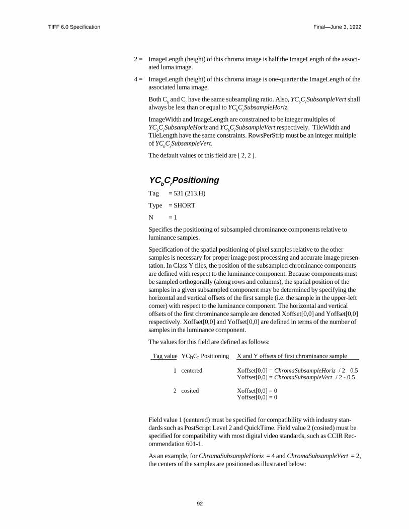
TIFF 6.0 Specification Final—June 3, 1992
92
2 = ImageLength (height) of this chroma image is half the ImageLength of the associ-ated luma image.
4 = ImageLength (height) of this chroma image is one-quarter the ImageLength of theassociated luma image.
Both Cb and C
r have the same subsampling ratio. Also, YC
bC
rSubsampleVert shall
always be less than or equal to YCbC
rSubsampleHoriz.
ImageWidth and ImageLength are constrained to be integer multiples ofYC
bC
rSubsampleHoriz and YC
bC
rSubsampleVert respectively. TileWidth and
TileLength have the same constraints. RowsPerStrip must be an integer multipleof YC
bC
rSubsampleVert.
The default values of this field are [ 2, 2 ].
YCbCrPositioningTag = 531 (213.H)
Type = SHORT
N = 1
Specifies the positioning of subsampled chrominance components relative toluminance samples.
Specification of the spatial positioning of pixel samples relative to the othersamples is necessary for proper image post processing and accurate image presen-tation. In Class Y files, the position of the subsampled chrominance componentsare defined with respect to the luminance component. Because components mustbe sampled orthogonally (along rows and columns), the spatial position of thesamples in a given subsampled component may be determined by specifying thehorizontal and vertical offsets of the first sample (i.e. the sample in the upper-leftcorner) with respect to the luminance component. The horizontal and verticaloffsets of the first chrominance sample are denoted Xoffset[0,0] and Yoffset[0,0]respectively. Xoffset[0,0] and Yoffset[0,0] are defined in terms of the number ofsamples in the luminance component.
The values for this field are defined as follows:
Tag value YCbCr Positioning X and Y offsets of first chrominance sample
1 centered Xoffset[0,0] = ChromaSubsampleHoriz / 2 - 0.5
Yoffset[0,0] = ChromaSubsampleVert / 2 - 0.5
2 cosited
Xoffset[0,0] = 0Yoffset[0,0] = 0
Field value 1 (centered) must be specified for compatibility with industry stan-dards such as PostScript Level 2 and QuickTime. Field value 2 (cosited) must bespecified for compatibility with most digital video standards, such as CCIR Rec-ommendation 601-1.
As an example, for ChromaSubsampleHoriz = 4 and ChromaSubsampleVert = 2,the centers of the samples are positioned as illustrated below:
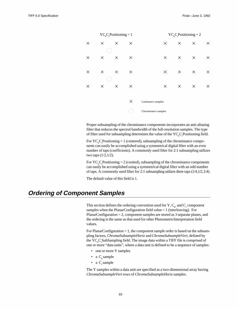
TIFF 6.0 Specification Final—June 3, 1992
93
YCbC
rPositioning = 1 YC
bC
rPositioning = 2
Luminance samples
Chrominance samples
Proper subsampling of the chrominance components incorporates an anti-aliasingfilter that reduces the spectral bandwidth of the full-resolution samples. The typeof filter used for subsampling determines the value of the YC
bC
rPositioning field.
For YCbC
rPositioning = 1 (centered), subsampling of the chrominance compo-
nents can easily be accomplished using a symmetrical digital filter with an evennumber of taps (coefficients). A commonly used filter for 2:1 subsampling utilizestwo taps (1/2,1/2).
For YCbC
rPositioning = 2 (cosited), subsampling of the chrominance components
can easily be accomplished using a symmetrical digital filter with an odd numberof taps. A commonly used filter for 2:1 subsampling utilizes three taps (1/4,1/2,1/4).
The default value of this field is 1.
Ordering of Component Samples
This section defines the ordering convention used for Y, Cb, and C
r component
samples when the PlanarConfiguration field value = 1 (interleaving). ForPlanarConfiguration = 2, component samples are stored as 3 separate planes, andthe ordering is the same as that used for other PhotometricInterpretation fieldvalues.
For PlanarConfiguration = 1, the component sample order is based on the subsam-pling factors, ChromaSubsampleHoriz and ChromaSubsampleVert, defined bythe YC
bC
rSubSampling field. The image data within a TIFF file is comprised of
one or more “data units”, where a data unit is defined to be a sequence of samples:
• one or more Y samples
• a Cb sample
• a Cr sample
The Y samples within a data unit are specified as a two-dimensional array havingChromaSubsampleVert rows of ChromaSubsampleHoriz samples.
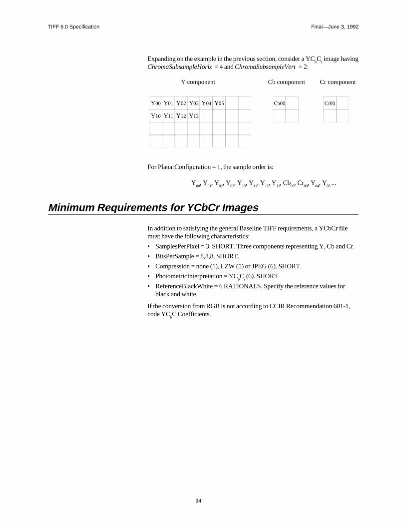
TIFF 6.0 Specification Final—June 3, 1992
94
Expanding on the example in the previous section, consider a YCbC
r image having
ChromaSubsampleHoriz = 4 and ChromaSubsampleVert = 2:
Y00 Y01
Y10 Y11
Y02
Y12
Cb00 Cr00
Y component Cb component Cr component
Y05Y04
Y13
Y03
For PlanarConfiguration = 1, the sample order is:
Y00
, Y01
, Y02
, Y03
, Y10
, Y11
, Y12
, Y13
, Cb00
, Cr00
, Y04
, Y05
...
Minimum Requirements for YCbCr Images
In addition to satisfying the general Baseline TIFF requirements, a YCbCr filemust have the following characteristics:
• SamplesPerPixel = 3. SHORT. Three components representing Y, Cb and Cr.
• BitsPerSample = 8,8,8. SHORT.
• Compression = none (1), LZW (5) or JPEG (6). SHORT.
• PhotometricInterpretation = YCbC
r (6). SHORT.
• ReferenceBlackWhite = 6 RATIONALS. Specify the reference values forblack and white.
If the conversion from RGB is not according to CCIR Recommendation 601-1,code YC
bC
rCoefficients.
TIFF 6.0 Specification Final—June 3, 1992
95
Section 22: JPEG Compression
Introduction
Image compression reduces the storage requirements of pictorial data. In addition,it reduces the time required for access to, communication with, and display ofimages. To address the standardization of compression techniques an internationalstandards group was formed: the Joint Photographic Experts Group (JPEG). JPEGhas as its objective to create a joint ISO/CCITT standard for continuous toneimage compression (color and grayscale).
JPEG decided that because of the broad scope of the standard, no one algorithmicprocedure was able to satisfy the requirements of all applications. It was decidedto specify different algorithmic processes, where each process is targeted to sat-isfy the requirements of a class of applications. Thus, the JPEG standard became a“toolkit” whereby the particular algorithmic “tools” are selected according to theneeds of the application environment.
The algorithmic processes fall into two classes: lossy and lossless. Those based onthe Discrete Cosine Transform (DCT) are lossy and typically provide for substan-tial compression without significant degradation of the reconstructed image withrespect to the source image.
The simplest DCT-based coding process is the baseline process. It provides acapability that is sufficient for most applications. There are additional DCT-basedprocesses that extend the baseline process to a broader range of applications.
The second class of coding processes is targeted for those applications requiringlossless compression. The lossless processes are not DCT-based and are utilizedindependently of any of the DCT-based processes.
This Section describes the JPEG baseline, the JPEG lossless processes, and theextensions to TIFF defined to support JPEG compression.
JPEG Baseline Process
The baseline process is a DCT-based algorithm that compresses images having 8bits per component. The baseline process operates only in sequential mode. Insequential mode, the image is processed from left to right and top to bottom in asingle pass by compressing the first row of data, followed by the second row, andcontinuing until the end of image is reached. Sequential operation has minimalbuffering requirements and thus permits inexpensive implementations.
The JPEG baseline process is an algorithm which inherently introduces error intothe reconstructed image and cannot be utilized for lossless compression. Thealgorithm accepts as input only those images having 8 bits per component. Imageswith fewer than 8 bits per component may be compressed using the baseline pro-cess algorithm by left justifying each input component within a byte before com-pression.
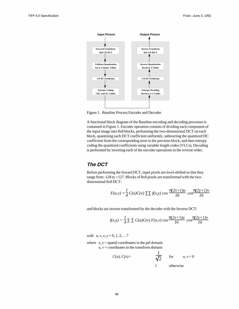
TIFF 6.0 Specification Final—June 3, 1992
96
Entropy Coding
2 DC and AC Tables
Forward Transform
8x8 2-D DCT
Uniform Quantization
Up to 4 Quant. Tables
1-D DC Prediction
Entropy Decoding
Receives 2+2 Tables
Inverse Transform
8x8 2-D IDCT
Inverse Quantization
Receives 4 Tables
1-D DC Prediction
Input Picture Output Picture
Figure 1. Baseline Process Encoder and Decoder
A functional block diagram of the Baseline encoding and decoding processes iscontained in Figure 1. Encoder operation consists of dividing each component ofthe input image into 8x8 blocks, performing the two-dimensional DCT on eachblock, quantizing each DCT coefficient uniformly, subtracting the quantized DCcoefficient from the corresponding term in the previous block, and then entropycoding the quantized coefficients using variable length codes (VLCs). Decodingis performed by inverting each of the encoder operations in the reverse order.
The DCTBefore performing the foward DCT, input pixels are level-shifted so that theyrange from -128 to +127. Blocks of 8x8 pixels are transformed with the two-dimensional 8x8 DCT:
F(u,v) = 14 C(u)C(v) ∑∑ f(x,y) cos
π(2x+1)u16 cos
π(2y+1)v16
and blocks are inverse transformed by the decoder with the Inverse DCT:
f(x,y) = 14 ∑ ∑ C(u)C(v) F(u,v) cos
π(2x+1)u16 cos
π(2y+1)v16
with u, v, x, y = 0, 1, 2, ... 7
where x, y = spatial coordinates in the pel domainu, v = coordinates in the transform domain
C(u), C(v) =12
for u, v = 0
1 otherwise
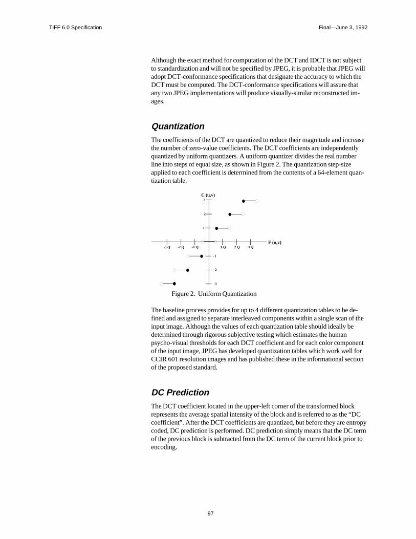
TIFF 6.0 Specification Final—June 3, 1992
97
Although the exact method for computation of the DCT and IDCT is not subjectto standardization and will not be specified by JPEG, it is probable that JPEG willadopt DCT-conformance specifications that designate the accuracy to which theDCT must be computed. The DCT-conformance specifications will assure thatany two JPEG implementations will produce visually-similar reconstructed im-ages.
QuantizationThe coefficients of the DCT are quantized to reduce their magnitude and increasethe number of zero-value coefficients. The DCT coefficients are independentlyquantized by uniform quantizers. A uniform quantizer divides the real numberline into steps of equal size, as shown in Figure 2. The quantization step-sizeapplied to each coefficient is determined from the contents of a 64-element quan-tization table.
1
2
3
-1
-2
-3
1 Q 3 Q-1 Q-2 Q-3 Q
C (u,v)
F (u,v)2 Q
Figure 2. Uniform Quantization
The baseline process provides for up to 4 different quantization tables to be de-fined and assigned to separate interleaved components within a single scan of theinput image. Although the values of each quantization table should ideally bedetermined through rigorous subjective testing which estimates the humanpsycho-visual thresholds for each DCT coefficient and for each color componentof the input image, JPEG has developed quantization tables which work well forCCIR 601 resolution images and has published these in the informational sectionof the proposed standard.
DC PredictionThe DCT coefficient located in the upper-left corner of the transformed blockrepresents the average spatial intensity of the block and is referred to as the “DCcoefficient”. After the DCT coefficients are quantized, but before they are entropycoded, DC prediction is performed. DC prediction simply means that the DC termof the previous block is subtracted from the DC term of the current block prior toencoding.
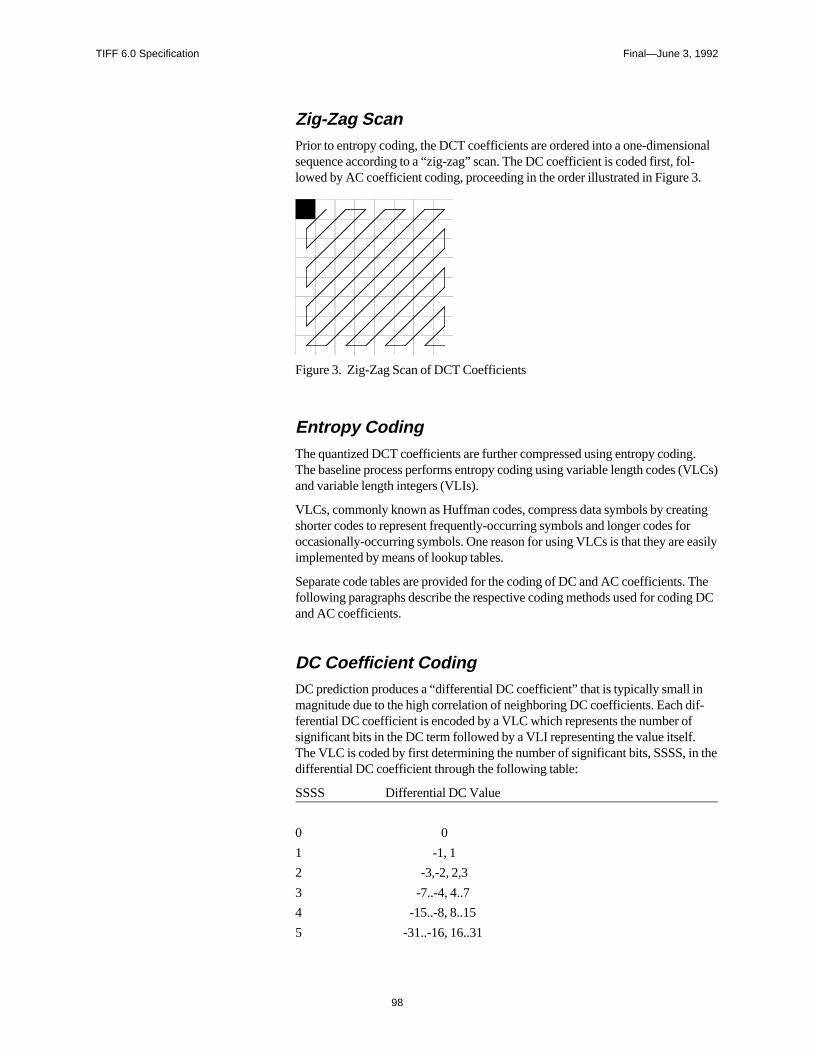
TIFF 6.0 Specification Final—June 3, 1992
98
Zig-Zag ScanPrior to entropy coding, the DCT coefficients are ordered into a one-dimensionalsequence according to a “zig-zag” scan. The DC coefficient is coded first, fol-lowed by AC coefficient coding, proceeding in the order illustrated in Figure 3.
Figure 3. Zig-Zag Scan of DCT Coefficients
Entropy CodingThe quantized DCT coefficients are further compressed using entropy coding.The baseline process performs entropy coding using variable length codes (VLCs)and variable length integers (VLIs).
VLCs, commonly known as Huffman codes, compress data symbols by creatingshorter codes to represent frequently-occurring symbols and longer codes foroccasionally-occurring symbols. One reason for using VLCs is that they are easilyimplemented by means of lookup tables.
Separate code tables are provided for the coding of DC and AC coefficients. Thefollowing paragraphs describe the respective coding methods used for coding DCand AC coefficients.
DC Coefficient CodingDC prediction produces a “differential DC coefficient” that is typically small inmagnitude due to the high correlation of neighboring DC coefficients. Each dif-ferential DC coefficient is encoded by a VLC which represents the number ofsignificant bits in the DC term followed by a VLI representing the value itself.The VLC is coded by first determining the number of significant bits, SSSS, in thedifferential DC coefficient through the following table:
SSSS Differential DC Value
0 0
1 -1, 1
2 -3,-2, 2,3
3 -7..-4, 4..7
4 -15..-8, 8..15
5 -31..-16, 16..31
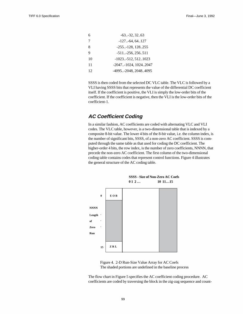
TIFF 6.0 Specification Final—June 3, 1992
99
6 -63..-32, 32..63
7 -127..-64, 64..127
8 -255..-128, 128..255
9 -511..-256, 256..511
10 -1023..-512, 512..1023
11 -2047..-1024, 1024..2047
12 -4095..-2048, 2048..4095
SSSS is then coded from the selected DC VLC table. The VLC is followed by aVLI having SSSS bits that represents the value of the differential DC coefficientitself. If the coefficient is positive, the VLI is simply the low-order bits of thecoefficient. If the coefficient is negative, then the VLI is the low-order bits of thecoefficient-1.
AC Coefficient CodingIn a similar fashion, AC coefficients are coded with alternating VLC and VLIcodes. The VLC table, however, is a two-dimensional table that is indexed by acomposite 8-bit value. The lower 4 bits of the 8-bit value, i.e. the column index, isthe number of significant bits, SSSS, of a non-zero AC coefficient. SSSS is com-puted through the same table as that used for coding the DC coefficient. Thehigher-order 4 bits, the row index, is the number of zero coefficients, NNNN, thatprecede the non-zero AC coefficient. The first column of the two-dimensionalcoding table contains codes that represent control functions. Figure 4 illustratesthe general structure of the AC coding table.
SSSS - Size of Non-Zero AC Coefs0 1 2 … 10 11…15
E O B
Z R L
0
.
.
.
15
NNNN
of
Zero
Run
Length
Figure 4. 2-D Run-Size Value Array for AC CoefsThe shaded portions are undefined in the baseline process
The flow chart in Figure 5 specifies the AC coefficient coding procedure. ACcoefficients are coded by traversing the block in the zig-zag sequence and count-
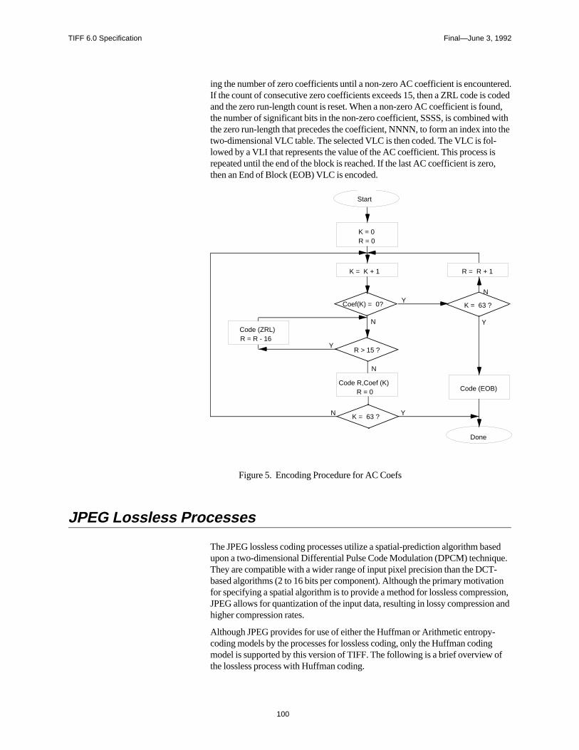
TIFF 6.0 Specification Final—June 3, 1992
100
ing the number of zero coefficients until a non-zero AC coefficient is encountered.If the count of consecutive zero coefficients exceeds 15, then a ZRL code is codedand the zero run-length count is reset. When a non-zero AC coefficient is found,the number of significant bits in the non-zero coefficient, SSSS, is combined withthe zero run-length that precedes the coefficient, NNNN, to form an index into thetwo-dimensional VLC table. The selected VLC is then coded. The VLC is fol-lowed by a VLI that represents the value of the AC coefficient. This process isrepeated until the end of the block is reached. If the last AC coefficient is zero,then an End of Block (EOB) VLC is encoded.
K = 0R = 0
K = K + 1 R = R + 1
K = 63 ?
R > 15 ?
Code R,Coef (K)R = 0
K = 63 ?
Start
Code (EOB)
Code (ZRL)R = R - 16
Y
N
N
N
N
Y
Y
Y
Coef(K) = 0?
Done
Figure 5. Encoding Procedure for AC Coefs
JPEG Lossless Processes
The JPEG lossless coding processes utilize a spatial-prediction algorithm basedupon a two-dimensional Differential Pulse Code Modulation (DPCM) technique.They are compatible with a wider range of input pixel precision than the DCT-based algorithms (2 to 16 bits per component). Although the primary motivationfor specifying a spatial algorithm is to provide a method for lossless compression,JPEG allows for quantization of the input data, resulting in lossy compression andhigher compression rates.
Although JPEG provides for use of either the Huffman or Arithmetic entropy-coding models by the processes for lossless coding, only the Huffman codingmodel is supported by this version of TIFF. The following is a brief overview ofthe lossless process with Huffman coding.
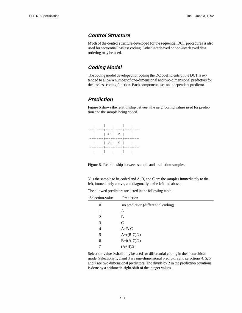
TIFF 6.0 Specification Final—June 3, 1992
101
Control StructureMuch of the control structure developed for the sequential DCT procedures is alsoused for sequential lossless coding. Either interleaved or non-interleaved dataordering may be used.
Coding ModelThe coding model developed for coding the DC coefficients of the DCT is ex-tended to allow a number of one-dimensional and two-dimensional predictors forthe lossless coding function. Each component uses an independent predictor.
PredictionFigure 6 shows the relationship between the neighboring values used for predic-tion and the sample being coded.
| | | | | --+---+---+---+---+-- | | C | B | | --+---+---+---+---+-- | | A | Y | | --+---+---+---+---+-- | | | | |
Figure 6. Relationship between sample and prediction samples
Y is the sample to be coded and A, B, and C are the samples immediately to theleft, immediately above, and diagonally to the left and above.
The allowed predictors are listed in the following table.
Selection-value Prediction
0 no prediction (differential coding)
1 A
2 B
3 C
4 A+B-C
5 A+((B-C)/2)
6 B+((A-C)/2)
7 (A+B)/2
Selection-value 0 shall only be used for differential coding in the hierarchicalmode. Selections 1, 2 and 3 are one-dimensional predictors and selections 4, 5, 6,and 7 are two dimensional predictors. The divide by 2 in the prediction equationsis done by a arithmetic-right-shift of the integer values.
TIFF 6.0 Specification Final—June 3, 1992
102
The difference between the prediction value and the input is calculated modulo2**16. Therefore, the prediction can also be treated as a modulo 2**16 value. Inthe decoder the difference is decoded and added, modulo 2**16, to the prediction.
Huffman Coding of the Prediction ErrorThe Huffman coding procedures defined for coding the DC coefficients are usedto code the modulo 2**16 differences. The table for DC coding is extended to 17entries that allows for coding of the modulo 2**16 differences.
Point Transformation Prior to Lossless CodingFor the lossless processes only, the input image data may optionally be scaled(quantized) prior to coding by specifying a nonzero value in the point transforma-tion parameter. Point transformation is defined to be division by a power of 2.
If the point transformation field is nonzero for a component, a point transforma-tion of the input is performed prior to the lossless coding. The input is divided by2**Pt, where Pt is the value of the point transform signaling field. The output ofthe decoder is rescaled to the input range by multiplying by 2**Pt. Note that thescaling of input and output can be performed by arithmetic shifts.
Overview of the JPEG Extension to TIFF
In extending the TIFF definition to include JPEG compressed data, it is necessaryto note the following:
• JPEG is effective only on continuous-tone color spaces:
Grayscale (Photometric Interpretation = 1)
RGB (Photometric Interpretation = 2)
CMYK (Photometric Interpretation = 5) (See the CMYK Images section.)
YCbC
r(Photometric Interpretation = 6) (See the YCbCr images section.)
• Color conversion to YCbC
r is often used as part of the compression process
because the chrominance components can be subsampled and compressed to agreater degree without significant visual loss of quality. Fields are defined todescribe how this conversion has taken place and the degree of subsamplingemployed (see the YCbCr Images section).
• New fields have been defined to specify the JPEG parameters used for com-pression and to allow quantization tables and Huffman code tables to be incor-porated into the TIFF file.
TIFF 6.0 Specification Final—June 3, 1992
103
• TIFF is compatible with compressed image data that conforms to the syntax ofthe JPEG interchange format for compressed image data. Fields are definedthat may be utilized to facilitate conversion from TIFF to interchange format.
• The PlanarConfiguration Field is used to specify whether or not the com-pressed data is interleaved as defined by JPEG. For any of the JPEG DCT-based processes, the interleaved data units are coded 8x8 blocks rather thancomponent samples.
• Although JPEG codes consecutive image blocks in a single contiguousbitstream, it is extremely useful to employ the concept of tiles in an image. TheTIFF Tiles section defines some new fields for tiles. These fields should bestored in place of the older fields for strips. The concept of tiling an image inboth dimensions is important because JPEG hardware may be limited in thesize of each block that is handled.
• Note that the nomenclature used in the TIFF specification is different from theJPEG Draft International Standardittee Draft (ISO DIS 10918-1) in somerespects. The following terms should be equated when reading this Section:
TIFF name JPEG DIS name
ImageWidth Number of Pixels
ImageLength Number of Lines
SamplesPerPixel Number of Components
JPEGQTable Quantization Table
JPEGDCTable Huffman Table for DC coefficients
JPEGACTable Huffman Table for AC coefficients
Strips and Tiles
The JPEG extension to TIFF has been designed to be consistent with the existingTIFF strip and tile structures and to allow quick conversion to and from thestream-oriented compressed image format defined by JPEG.
Compressed images conforming to the syntax of the JPEG interchange format canbe converted to TIFF simply by defining a single strip or tile for the entire imageand then concatenating the TIFF image description fields to the JPEG compressedimage data. The strip or tile offset field points directly to the start of the entropycoded data (not to a JPEG marker).
Multiple strips or tiles are supported in JPEG compressed images using restartmarkers. Restart markers, inserted periodically into the compressed image data,delineate image segments known as restart intervals. At the start of each restartinterval, the coding state is reset to default values, allowing every restart intervalto be decoded independently of previously decoded data. TIFF strip and tile off-sets shall always point to the start of a restart interval. Equivalently, each strip or
TIFF 6.0 Specification Final—June 3, 1992
104
tile contains an integral number of restart intervals. Restart markers need not bepresent in a TIFF file; they are implicitly coded at the start of every strip or tile.
To maximize interchangeability of TIFF files with other formats, a restriction isplaced on tile height for files containing JPEG-compressed image data conform-ing to the JPEG interchange format syntax. The restriction, imposed only whenthe tile width is shorter than the image width and when theJPEGInterchangeFormat Field is present and non-zero, states that the tile heightmust be equal to the height of one JPEG Minimum Coded Unit (MCU). Thisrestriction ensures that TIFF files may be converted to JPEG interchange formatwithout undergoing decompression.
Extensions to Existing Fields
CompressionTag = 259 (103.H)
Type = SHORT
N = 1
This Field indicates the type of compression used. The new value is:
6 = JPEG
JPEG Fields
JPEGProcTag = 512 (200.H)
Type = SHORT
N = 1
This Field indicates the JPEG process used to produce the compressed data. Thevalues for this field are defined to be consistent with the numbering conventionused in ISO DIS 10918-2. Two values are defined at this time.
1= Baseline sequential process
14= Lossless process with Huffman coding
When the lossless process with Huffman coding is selected by this Field, theHuffman tables used to encode the image are specified by the JPEGDCTablesfield, and the JPEGACTables field is not used.
Values indicating JPEG processes other than those specified above will be definedin the future.
TIFF 6.0 Specification Final—June 3, 1992
105
Not all of the fields described in this section are relevant to the JPEG processselected by this Field. The following table specifies the fields that are applicableto each value defined by this Field.
Tag Name JPEGProc =1 JPEGProc =14
JPEGInterchangeFormat X X
JPEGInterchangeFormatLength X X
JPEGRestart Interval X X
JPEGLosslessPredictors X
JPEGPointTransforms X
JPEGQTables X
JPEGDCTables X X
JPEGACTables X
This Field is mandatory whenever the Compression Field is JPEG (no default).
JPEGInterchangeFormatTag = 513 (201.H)
Type = LONG
N = 1
This Field indicates whether a JPEG interchange format bitstream is present in theTIFF file. If a JPEG interchange format bitstream is present, then this Field pointsto the Start of Image (SOI) marker code.
If this Field is zero or not present, a JPEG interchange format bitstream is notpresent.
JPEGInterchangeFormatLengthTag = 514 (202.H)
Type = LONG
N = 1
This Field indicates the length in bytes of the JPEG interchange format bitstream.This Field is useful for extracting the JPEG interchange format bitstream withoutparsing the bitstream.
This Field is relevant only if the JPEGInterchangeFormat Field is present and isnon-zero.
JPEGRestartIntervalTag = 515 (203.H)
Type = SHORT
N = 1
TIFF 6.0 Specification Final—June 3, 1992
106
This Field indicates the length of the restart interval used in the compressed imagedata. The restart interval is defined as the number of Minimum Coded Units(MCUs) between restart markers.
Restart intervals are used in JPEG compressed images to provide support formultiple strips or tiles. At the start of each restart interval, the coding state is resetto default values, allowing every restart interval to be decoded independently ofpreviously decoded data. TIFF strip and tile offsets shall always point to the startof a restart interval. Equivalently, each strip or tile contains an integral number ofrestart intervals. Restart markers need not be present in a TIFF file; they are im-plicitly coded at the start of every strip or tile.
See the JPEG Draft International Standard (ISO DIS 10918-1) for more informa-tion about the restart interval and restart markers.
If this Field is zero or is not present, the compressed data does not contain restartmarkers.
JPEGLosslessPredictorsTag = 517 (205.H)
Type = SHORT
N = SamplesPerPixel
This Field points to a list of lossless predictor-selection values, one per compo-nent.The allowed predictors are listed in the following table.
Selection-value Prediction
1 A
2 B
3 C
4 A+B-C
5 A+((B-C)/2)
6 B+((A-C)/2)
7 (A+B)/2
A, B, and C are the samples immediately to the left, immediately above, anddiagonally to the left and above the sample to be coded, respectively.
See the JPEG Draft International Standard (ISO DIS 10918-1) for more details.
This Field is mandatory whenever the JPEGProc Field specifies one of thelossless processes (no default).
JPEGPointTransformsTag = 518 (206.H)
Type = SHORT
N = SamplesPerPixel
TIFF 6.0 Specification Final—June 3, 1992
107
This Field points to a list of point transform values, one per component. This Fieldis relevant only for lossless processes.
If the point transformation value is nonzero for a component, a point transforma-tion of the input is performed prior to the lossless coding. The input is divided by2**Pt, where Pt is the point transform value. The output of the decoder is rescaledto the input range by multiplying by 2**Pt. Note that the scaling of input andoutput can be performed by arithmetic shifts.
See the JPEG Draft International Standard (ISO DIS 10918-1) for more details.The default value of this Field is 0 for each component (no scaling).
JPEGQTablesTag = 519 (207.H)
Type = LONG
N = SamplesPerPixel
This Field points to a list of offsets to the quantization tables, one per component.Each table consists of 64 BYTES (one for each DCT coefficient in the 8x8 block).The quantization tables are stored in zigzag order.
See the JPEG Draft International Standard (ISO DIS 10918-1) for more details.
It is strongly recommended that, within the TIFF file, each component be assignedseparate tables. This Field is mandatory whenever the JPEGProc Field specifies aDCT-based process (no default).
JPEGDCTablesTag = 520 (208.H)
Type = LONG
N = SamplesPerPixel
This Field points to a list of offsets to the DC Huffman tables or the losslessHuffman tables, one per component.
The format of each table is as follows:
16 BYTES of “BITS”, indicating the number of codes of lengths 1 to 16;
Up to 17 BYTES of “VALUES”, indicating the values associated withthose codes, in order of length.
See the JPEG Draft International Standard (ISO DIS 10918-1) for more details.
It is strongly recommended that, within the TIFF file, each component be assignedseparate tables. This Field is mandatory for all JPEG processes (no default).
JPEGACTablesTag = 521 (209.H)
Type = LONG
N = SamplesPerPixel
TIFF 6.0 Specification Final—June 3, 1992
108
This Field points to a list of offsets to the Huffman AC tables, one per component.The format of each table is as follows:
16 BYTES of “BITS”, indicating the number of codes of lengths 1 to 16;
Up to 256 BYTES of “VALUES”, indicating the values associated withthose codes, in order of length.
See the JPEG Draft International Standard (ISO DIS 10918-1) for more details.
It is strongly recommended that, within the TIFF file, each component be assignedseparate tables. This Field is mandatory whenever the JPEGProc Field specifies aDCT-based process (no default).
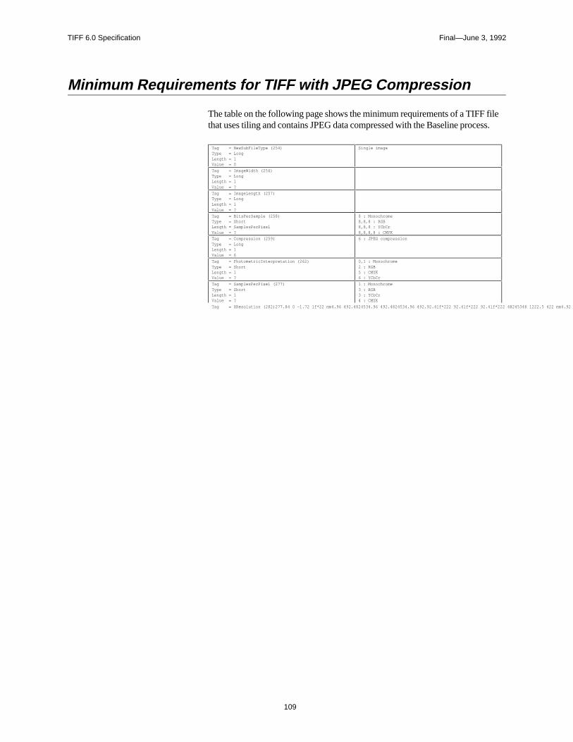
TIFF 6.0 Specification Final—June 3, 1992
109
Minimum Requirements for TIFF with JPEG Compression
The table on the following page shows the minimum requirements of a TIFF filethat uses tiling and contains JPEG data compressed with the Baseline process.
Tag = NewSubFileType (254)Type = LongLength = 1Value = 0
Single image
Tag = ImageWidth (256)Type = LongLength = 1Value = ?
Tag = ImageLength (257)Type = LongLength = 1Value = ?
Tag = BitsPerSample (258)Type = ShortLength = SamplesPerPixelValue = ?
8 : Monochrome8,8,8 : RGB8,8,8 : YCbCr 8,8,8,8 : CMYK
Tag = Compression (259)Type = LongLength = 1Value = 6
6 : JPEG compression
Tag = PhotometricInterpretation (262)Type = ShortLength = 1Value = ?
0,1 : Monochrome2 : RGB5 : CMYK6 : YCbCr
Tag = SamplesPerPixel (277)Type = ShortLength = 1Value = ?
1 : Monochrome3 : RGB3 : YCbCr4 : CMYK
Tag = XResolution (282)322051 225.84 462.96 Tm 0 Tc 0 Tag = Samples62.96 Tm282)5 517.44 l 2 -j 0 -1.1508 Td (LenMultiple of 8 2 -1.1Tj 0 -1.1r92.f (277.84 0 -1.72 l f371234.96 491.9371234.l6 491.9371234.l6 491.93712 491.52 l3712 491.52 l3712 491.52 l3712.484601 76 2.5 371234.96 42 4913712.48462.48 l 3712.48462.48 l 3712 491.4892.483712 491.52 2.5 3712 491.52 2.5 371234.348 l48 491.371234.96 222 46371234.34 222 46371234.34 222 463712 491.48 491.3712 491.48 491.3712 491.48 491.371234.348 l482.48371234.96 2.98 371234.342.48 l f*371234.342.48 l f*3712 491..52 24.3712 491.482.483712 491.482.4837128.7348 l.52 m 5371234.9668.7 l 3737128.73468.7 l 3737128.73468.7 l 373712 491..52 m 53712 491..52 m 53712 491..52 m 53712.484601 76 5370.56.96 491.9370.56.l6 491.93.4601.96 493470815.76 53470815.76 5370.0615.76 5370.56.348 l48 491.370.56.96 222 46370.56.34 222 463.4601 222 463470815.48 491.3470815.48 491.370.0615.48 491.370.56.348 l.52 m 5370.56.9668.7 l 37370.56.3468.7 l 373.460168.7 l 373470815..52 m 53470815..52 m 5370.0615..52 m 5370.56.4601 468.7 l 534.96 468.7 l 534.96 491.02 l 534.96 49136 4* Q BT 0 Tr 0 g /F19 1 Tile282))T(323051 225.84 4ution ( 0 Tc 0 Tag = Samples62.96 Tm282)5 517.44 l 2 -j 0 -1.150848d (LenMultiple of 8 2 -1.1Tj 0 -1.1r92.f (277.84 0 -1.72 l f347028.96 491.9347028.l6 491.9347028.l6 491.93462.815. l f3462.815. l f3462.815. l f347028.l601 76 2.5 347028.96 42 491347028.l62.48 l 347028.l62.48 l 3462.815.4892.483462.815. l 2.5 3462.815. l 2.5 347028.l601 48 491.347028.96 222 46347028.l62.48 46347028.l62.48 463462.815.48 491.3462.815.48 491.3462.815.48 491.347028.l601 482.48347028.96 2.98 347028.l62.48 l f*347028.l62.48 l f*3462.815..52 24.3462.815.482.483462.815.482.48347028.l601 .52 m 5347028.9668.7 l 37347028.l62..7 l 37347028.l62..7 l 373462.815..52 9673462.815..52 9673462.815..52 967347028.l601 76 7346234.96 491.9346234.l6 491.9342 76.l6 491.9342 2615.76 5342 2615.76 5346 4215. l f346234.348 l48 491.346234.962.48 46346234.34 222 46342 76.l6 222 46342 2615.48 491.342 2615.48 491.346 4215.48 491.346234.l601 .52 m 5346234.962..7 l 3734623.73468.7 l 37342 76.l668.7 l 37342 2.4601 493.2342 2.4601 493.2346 4215..52 m 5346234.4601 468.7 l 534.96 468.7 l 534.96 491.02 l 534.96 4913192.48* Q BT 0 Tr 0 g /F19 1 TileOffsetsT(324051 225.84 4ution ( 0 Tc 0 TLong = Samples62.96 Tm282))Tj Number of tiles = Samples62.96 Tm5 517.44 l 2 -1.1Tj 0 -1.1r92.f (277.84 0 -1.72 l f342 048 : 491.9342 04.l6 491.9342 04.l6 491.9342.5415. l f342.5415. l f342.5415. l f34320484601 l 2.5 342 048 : 42 4913432048462.48 l 3432048462.48 l 342.5415.4892.48342.5415. l 2.5 342.5415. l 2.5 34320484601 48 491.342 048 : 222 46342 04.l6 222 46342 04.l6 222 46342.5415.48 491.342.5415.48 491.342.5415.48 491.34320484601 482.48342 048 : 2.98 3432048462.48 l f*3432048462.48 l f*342.5415..52 24.342.5415.482.48342.5415.482.4834320484601 1 493.2342 048 :68.7 l 37342 04.l668.7 l 37342 04.l668.7 l 37342.5415..52 967342.5415..52 967342.5415..52 96734320484601 l 7342.08.96 491.9342.08.l6 491.9299234.l6 491.92992 491.52 l2992 491.52 l3212.815. l f342.08.l601 48 491.342.08.96 222 46342.08.l62.48 46299234.l62.48 462992 491.48 491.2992 491.48 491.3212.815.48 491.342.08.4601 1 493.2342.08.9668.7 l 37342.08.l62..7 l 37299234.l62..7 l 372992 491..52 m 52992 491..52 m 53212.815.1 493.2342.08.4601 468.7 l 534.96 468.7 l 534.96 491.02 l 534.96 491293234.* Q BT 0 Tr 0 g /F19 1 TileByteCountsT(325051 225.84 4ution ( 0 Tc 0 TLong = Samples62.96 Tm282)277.84 0 -1.72 l f298.8.96 491.9298.8.l6 491.9298.8.l6 491.9298.391.52 l298.391.52 l298.391.52 l298.8.l601 76 2.5 298.8.96 42 491298.8.l62.48 l 298.8.l62.48 l 298.315.4892.48298.391.52 2.5 298.391.52 2.5 298.8.l601 48 491.298.8.962.48 46298.8.l62.48 46298.8.l62.48 46298.391.48 491.298.391.48 491.298.391.48 491.298.8.l601 482.48298.8.962..98 298.8.l62.48 l f*298.8.l62.48 l f*298.315..52 24.298.391.482.48298.391.482.48298.8.4601 1 493.2298.8.962..7 l 37298.8.l62..7 l 37298.8.l62..7 l 37298.391..52 m 5298.391..52 m 5298.391..52 m 5298.8.l601 76 7297 49196 491.9297 491l6 491.9275028.l6 491.92742.815. l f2742.815. l f297 3415. l f297 84.l601 48 491.297 491962.48 46297 84.l62.48 46275028.l62.48 462742.815.48 491.2742.815.48 491.297 3415.48 491.297 4914601 1 493.2297 491962..7 l 37297 491462..7 l 37275028.l62..7 l 372742.815..52 9672742.815..52 967297 3415.1 493.2297 4914601 468.7 l 534.96 468.7 l 534.96 491.02 l 534.96 491269028.* Q BT 0 Tr 0 g /F19 1 JPEGProcT(512051 225.84 462.96 Tm 0 Tc 0 Tag = Samplesution (282)
TIFF 6.0 Specification Final—June 3, 1992
110
Section 23: CIE L*a*b* Images
What is CIE L*a*b*?
CIE La*b* is a color space that is colorimetric, has separate lightness and chromachannels, and is approximately perceptually uniform. It has excellent applicabilityfor device-independent manipulation of continuous tone images. These attributesmake it an excellent choice for many image editing functions.
1976 CIEL*a*b* is represented as a Euclidean space with the following threequantities plotted along axes at right angles: L* representing lightness, a* repre-senting the red/green axis, and b* representing the yellow/blue axis. The formulasfor 1976 CIE L*a*b* follow:
L*=116(Y/Yn)1/3-16 for Y/Yn > 0.008856
L*=903.3(Y/Yn) for Y/Yn <= 0.008856 *see note below.
a*=500[(X/Xn)1/3-(Y/Yn)1/3]
b*=200[(Y/Yn)1/3-(Z/Zn)1/3].
where Xn,Y
n, and Z
n are the CIE X, Y, and Z tristimulus values of an appropriate
reference white. Also, if any of the ratios X/Xn, Y/Y
n, or Z/Z
n is equal to or less than
0.008856, it is replaced in the formulas with
7.787F + 16/116,
where F is X/Xn, Y/Y
n, or Z/Z
n, as appropriate (note: these low-light conditions are
of no relevance for most document-imaging applications). Tiff is defined suchthat each quantity be encoded with 8 bits. This provides 256 levels of L* lightness;256 levels (+/- 127) of a*, and 256 levels (+/- 127) of b*. Dividing the 0-100range of L* into 256 levels provides lightness steps that are less than half the sizeof a “just noticeable difference”. This eliminates banding, even under conditionsof substantial tonal manipulation. Limiting the theoretically unbounded a* and b*ranges to +/- 127 allows encoding in 8 bits without eliminating any but the mostsaturated self-luminous colors. It is anticipated that the rare specialized applica-tions requiring support of these extreme cases would be unlikely to use CIELABanyway. All object colors, in fact all colors within the theoretical MacAdam lim-its, fall within the +/- 127 a*/b* range.
TIFF 6.0 Specification Final—June 3, 1992
111
The TIFF CIELAB Fields
PhotometricInterpretationTag = 262 (106.H)
Type = SHORT
N = 1
8 = 1976 CIE L*a*b*
Usage of other Fields.BitsPerSample: 8
SamplesPerPixel - ExtraSamples: 3 for L*a*b*, 1 implies L* only, for mono-chrome data.
Compression: same as other multi-bit formats. JPEG compression applies.
PlanarConfiguration: both chunky and planar data could be supported.
WhitePoint: does not apply
PrimaryChromaticities: does not apply.
TransferFunction: does not apply
Alpha Channel information will follow the lead of other data types.
The reference white for this data type is the perfect reflecting diffuser (100%diffuse reflectance at all visible wavelengths). The L* range is from 0 (perfectabsorbing black) to 100 (perfect reflecting diffuse white). The a* and b* rangeswill be represented as signed 8 bit values having the range -127 to +127.
Converting between RGB and CIELAB, a Caveat
The above CIELAB formulae are derived from CIE XYZ. Converting fromCIELAB to RGB requires an additional set of formulae for converting betweenRGB and XYZ. For standard NTSC primaries these are:
0.6070 0.1740 0.2000 R X
0.2990 0.5870 0.1140 * G = Y
0.0000 0.0660 1.1110 B Z
Generally, D65 illumination is used and a perfect reflecting diffuser is used for thereference white.
Since CIELAB is not a directly displayable format, some conversion to RGB willbe required. While look-up table accelerated CIELAB to RGB conversion iscertainly possible and fast, TIFF writers may choose to include a low resolutionRGB subfile as an integral part of TIFF CIELAB.
TIFF 6.0 Specification Final—June 3, 1992
112
Color Difference Measurements in CIELABThe differences between two colors in L*, a*, and b* are denoted by DL*, Da*,and Db*, respectively, with the total (3-dimensional) color difference representedas:
∆E*ab = [(∆E*)2+(∆a*)2+(∆b*)2]1/2.
This color difference can also be expressed in terms of L*, C*, and a measure ofhue. In this case, h
ab is not used because it is an angular measure and cannot be
combined with L* and C* directly. A linear-distance form of hue is used instead:
CIE 1976 a,b hue-difference, ∆H*ab
∆H*ab = [(∆E*)2-(∆L*)2-(∆C*)2]1/2.
where DC* is the chroma difference between the two colors. The total color dif-ference expression using this hue-difference is:
∆E*ab = [(∆L*)2+(∆H*)2+(∆b*)2]1/2.
It is important to remember that color difference is 3-dimensional: much more canbe learned from a DL*a*b* triplet than from a single DE value. The DL*C*H*form is often the most useful since it gives the error information in a form that hasmore familiar perception correlates. Caution is in order, however, when usingDH* for large hue differences since it is a straight-line approximation of a curvedhue distance.
The Merits of CIELAB
Colorimetric.First and foremost, CIELAB is colorimetric. It is traceable to the internationally-recognized standard CIE 1931 Standard Observer. This insures that it encodescolor in a manner that is accurately modeled after the human vision system. Col-ors seen as matching are encoded identically, and colors seen as not matching areencoded differently. CIELAB provides an unambiguous definition of color with-out the necessity of additional information such as with RGB (primarychromaticities, white point, and gamma curves).
Device Independent.Unlike RGB spaces which associate closely with physical phosphor colors,CIELAB contains no device association. CIELAB is not tailored for one device ordevice type at the expense of all others.
TIFF 6.0 Specification Final—June 3, 1992
113
Full Color Gamut.Any one image or imaging device usually encounters a very limited subset of theentire range of humanly-perceptible color. Collectively, however, these imagesand devices span a much larger gamut of color. A truly versatile exchange colorspace should encompass all of these colors, ideally providing support for all vis-ible color. RGB, PhotoYCC, YCbCr, and other display spaces suffer from gamutlimitations that exclude significant regions of easily printable colors. CIELAB isdefined for all visible color.
EfficiencyA good exchange space will maximize accuracy of translations between itself andother spaces. It will represent colors compactly for a given accuracy. These at-tributes are provided through visual uniformity. One of the greatest disadvantagesof the classic CIE system (and RGB systems as well) is that colors within it are notequally spaced visually. Encoding full-color images in a linear-intensity space,such as the typical RGB space or, especially, the XYZ space, requires a very largerange (greater than 8-bits/primary) to eliminate banding artifacts. Adopting a non-linear RGB space improves the efficiency but not nearly to the extent as with aperceptually uniform space where these problems are nearly eliminated. A uni-form space is also more efficiently compressed (see below).
Public Domain / Single StandardCIELAB maintains no preferential attachments to any private organization. Itsexistence as a single standard leaves no room for ambiguity. Since 1976, CIELABhas continually gained popularity as a widely-accepted and heavily-used standard.
Luminance/Chrominance Separation.The advantages for image size compression made possible by having a separatelightness or luminance channel are immense. Many such spaces exist. The degreeto which the luminance information is fully-isolated into a single channel is animportant consideration. Recent studies (Kasson and Plouffe of IBM) supportCIELAB as a leading candidate placing it above CIELUV, YIQ, YUV, YCC, andXYZ.
Other advantages support a separate lightness or luminance channel. Tone andcontrast editing and detail enhancement are most easily accomplished with such achannel. Conversion to a black and white representation is also easiest with thistype of space.
When the chrominance channels are encoded as opponents as with CIELAB,there are other compression, image manipulation, and white point handling ad-vantages.
TIFF 6.0 Specification Final—June 3, 1992
114
Compressibility (Data).Opponent spaces such as CIELAB are inherently more compressible thantristimulus spaces such as RGB. The chroma content of an image can be com-pressed to a greater extent, without objectionable loss, than can the lightness con-tent. The opponent arrangement of CIELAB allows for spatial subsampling andefficent compression using JPEG.
Compressibility (Gamut).Adjusting the color range of an image to match the capabilities of the intendedoutput device is a critical function within computational color reproduction. Lu-minance/chrominance separation, especially when provided in a polar form, isdesirable for facilitating gamut compression. Accurate gamut compression in atri-linear color space is difficult.
CIELAB has a polar form (metric hue angle, and metric chroma, described be-low) that serves compression needs fairly well. Because CIELAB is not perfectlyuniform, problems can arise when compressing along constant hue lines. Notice-able hue errors are sometimes introduced. This problem is no less severe withother contending color spaces.
This polar form also provides advantages for local color editing of images. Thepolar form is not proposed as part of the TIFF addition.
Getting the Most from CIELAB
Image EditorsThe advantages of image editing within a perceptually uniform polar color spaceare tremendous. A detailed description of these advantages is beyond the scope ofthis section. As previously mentioned, many common tonal manipulation tasksare most efficiently performed when only a single channel is affected. Edge en-hancement, contrast adjustment, and general tone-curve manipulation all ideallyaffect only the lightness component of an image.
A perceptual polar space works excellently for specifying a color range for mask-ing purposes. For example, a red shirt can be quickly changed to a green shirtwithout drawing an outline mask. The operation can be performed with a loosely,quickly-drawn mask region combined with a hue (and perhaps chroma) range thatencompasses the shirt’s colors. The hue component of the shirt can then be ad-justed, leaving the lightness and chroma detail in place.
Color cast adjustment is easily realized by shifting either or both of the chromachannels over the entire image or blending them over the region of interest.
Converting from CIELAB to a device specific spaceFor fast conversion to an RGB display, CIELAB can be decoded using 3x3matrixing followed by gamma correction. The computational complexity required
TIFF 6.0 Specification Final—June 3, 1992
115
for accurate CRT display is the same with CIELAB as with extended luminance-chrominance spaces.
Converting CIELAB for accurate printing on CMYK devices requires computa-tional complexity no greater than with accurate conversion from any other colori-metric space. Gamut compression becomes one of the more significant tasks forany such conversion.
TIFF 6.0 Specification Final—June 3, 1992
116
Part 3: AppendicesPart 3 contains additional information that is not part of the TIFF specification,but may be of use to developers.
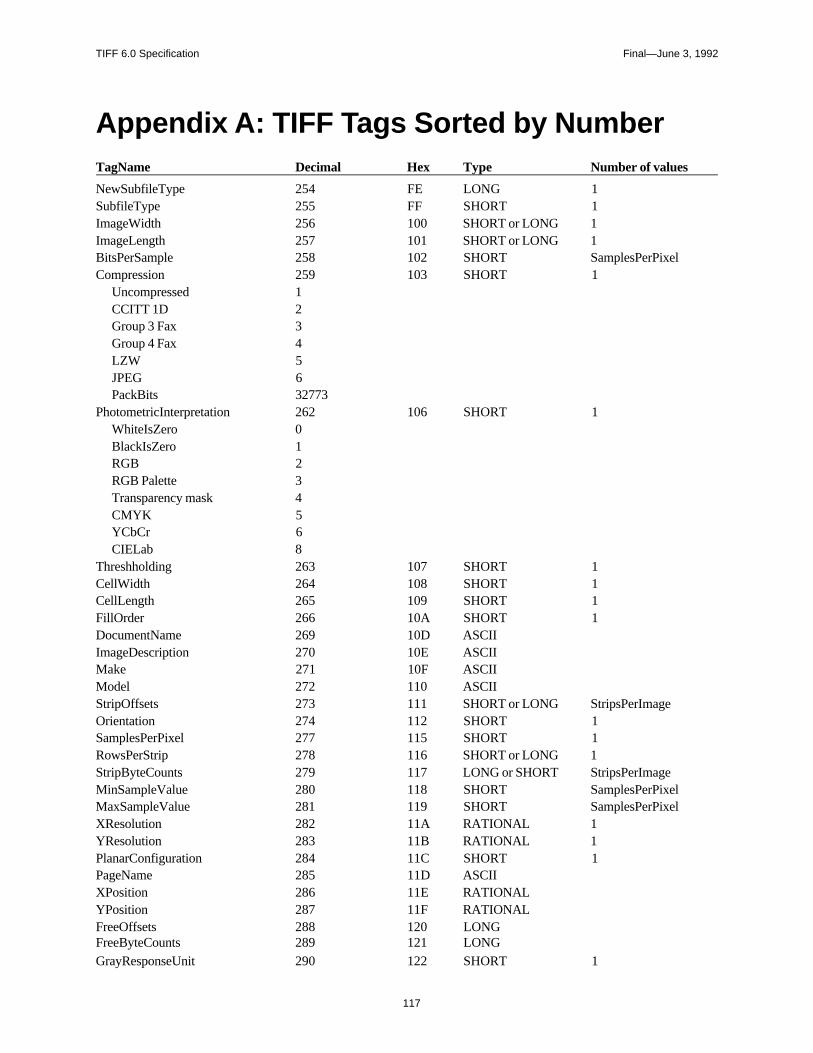
TIFF 6.0 Specification Final—June 3, 1992
117
Appendix A: TIFF Tags Sorted by NumberTagName Decimal Hex Type Number of values
NewSubfileType 254 FE LONG 1SubfileType 255 FF SHORT 1ImageWidth 256 100 SHORT or LONG 1ImageLength 257 101 SHORT or LONG 1BitsPerSample 258 102 SHORT SamplesPerPixelCompression 259 103 SHORT 1
Uncompressed 1CCITT 1D 2Group 3 Fax 3Group 4 Fax 4LZW 5JPEG 6PackBits 32773
PhotometricInterpretation 262 106 SHORT 1WhiteIsZero 0BlackIsZero 1RGB 2RGB Palette 3Transparency mask 4CMYK 5YCbCr 6CIELab 8
Threshholding 263 107 SHORT 1CellWidth 264 108 SHORT 1CellLength 265 109 SHORT 1FillOrder 266 10A SHORT 1DocumentName 269 10D ASCIIImageDescription 270 10E ASCIIMake 271 10F ASCIIModel 272 110 ASCIIStripOffsets 273 111 SHORT or LONG StripsPerImageOrientation 274 112 SHORT 1SamplesPerPixel 277 115 SHORT 1RowsPerStrip 278 116 SHORT or LONG 1StripByteCounts 279 117 LONG or SHORT StripsPerImageMinSampleValue 280 118 SHORT SamplesPerPixelMaxSampleValue 281 119 SHORT SamplesPerPixelXResolution 282 11A RATIONAL 1YResolution 283 11B RATIONAL 1PlanarConfiguration 284 11C SHORT 1PageName 285 11D ASCIIXPosition 286 11E RATIONALYPosition 287 11F RATIONALFreeOffsets 288 120 LONGFreeByteCounts 289 121 LONGGrayResponseUnit 290 122 SHORT 1
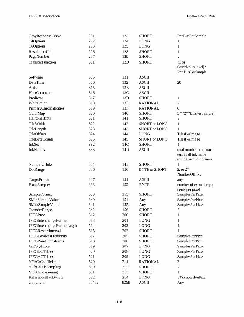
TIFF 6.0 Specification Final—June 3, 1992
118
GrayResponseCurve 291 123 SHORT 2**BitsPerSampleT4Options 292 124 LONG 1T6Options 293 125 LONG 1ResolutionUnit 296 128 SHORT 1PageNumber 297 129 SHORT 2TransferFunction 301 12D SHORT 1 or
SamplesPerPixel*2** BitsPerSample
Software 305 131 ASCIIDateTime 306 132 ASCII 20Artist 315 13B ASCIIHostComputer 316 13C ASCIIPredictor 317 13D SHORT 1WhitePoint 318 13E RATIONAL 2PrimaryChromaticities 319 13F RATIONAL 6ColorMap 320 140 SHORT 3 * (2**BitsPerSample)HalftoneHints 321 141 SHORT 2TileWidth 322 142 SHORT or LONG 1TileLength 323 143 SHORT or LONG 1TileOffsets 324 144 LONG TilesPerImageTileByteCounts 325 145 SHORT or LONG TilesPerImageInkSet 332 14C SHORT 1InkNames 333 14D ASCII total number of charac
ters in all ink namestrings, including zeros
NumberOfInks 334 14E SHORT 1DotRange 336 150 BYTE or SHORT 2, or 2*
NumberOfInksTargetPrinter 337 151 ASCII anyExtraSamples 338 152 BYTE number of extra compo-
nents per pixelSampleFormat 339 153 SHORT SamplesPerPixelSMinSampleValue 340 154 Any SamplesPerPixelSMaxSampleValue 341 155 Any SamplesPerPixelTransferRange 342 156 SHORT 6JPEGProc 512 200 SHORT 1JPEGInterchangeFormat 513 201 LONG 1JPEGInterchangeFormatLngth 514 202 LONG 1JPEGRestartInterval 515 203 SHORT 1JPEGLosslessPredictors 517 205 SHORT SamplesPerPixelJPEGPointTransforms 518 206 SHORT SamplesPerPixelJPEGQTables 519 207 LONG SamplesPerPixelJPEGDCTables 520 208 LONG SamplesPerPixelJPEGACTables 521 209 LONG SamplesPerPixelYCbCrCoefficients 529 211 RATIONAL 3YCbCrSubSampling 530 212 SHORT 2YCbCrPositioning 531 213 SHORT 1ReferenceBlackWhite 532 214 LONG 2*SamplesPerPixelCopyright 33432 8298 ASCII Any
TIFF 6.0 Specification Final—June 3, 1992
119
Appendix B: Operating SystemConsiderations
Extensions and Filetypes
The recommended MS-DOS, UNIX, and OS/2 file extension for TIFF files is“.TIF”.
On an Apple Macintosh computer, the recommended Filetype is “TIFF”. It is agood idea to also name TIFF files with a “.TIF” extension so that they can easilyimported if transferred to a different operating system.
TIFF 6.0 Specification Final—June 3, 1992
120
Index
Symbols
42 13
A
Aldus Developers Desk 8alpha data 31
associated 69ANSI IT8 71Appendices 116AppleLink 8Artist 28ASCII 15
B
Baseline TIFF 11big-endian 13BitsPerSample 22, 29BlackIsZero 17, 37BYTE data type 15
C
CCITT 17, 30, 49CellLength 29CellWidth 29chunky format 38CIELAB images 110clarifications 6Class B 21Class G 22Class P 23Class R 25Classes 7CMYK Images 66ColorMap 23, 29ColorResponseCurves. See
TransferFunctioncompatibility 6compliance 12component 28compositing. See alpha data:
associated
compression 17, 30CCITT 49JPEG 95LZW 57Modified Huffman 43PackBits 42
CompuServe 8Copyright 31Count 14, 15, 16
D
DateTime 31default values 28Differencing Predictor 64DocumentName 55DotRange 71DOUBLE 16Duff, Tom 79
E
ExtraSamples 31, 77
F
Facsimile 49file extension 119filetype 119FillOrder 32FLOAT 16FreeByteCounts 33FreeOffsets 33
G
GrayResponseCurve 33, 73, 85GrayResponseUnit 33Group 3 17, 30Group3Options 51Group4Options 52
H
HalftoneHints 72Hexadecimal 12high fidelity color 69HostComputer 34
I
IFD. See image file directoryII 13image 28image file directory 13, 14image file header 13ImageDescription 34ImageLength 18, 27, 34ImageWidth 18, 27, 34InkNames 70InkSet 70
J
JPEG compression 95baseline 95discrete cosine trans-form 95entropy coding 98lossless processes 100quantization 97
JPEGACTables 107JPEGDCTables 107JPEGInterchangeFormat 105JPEGInterchangeFormatLength 105JPEGLosslessPredictors 106JPEGPointTransforms 106JPEGProc 104JPEGQTables 107JPEGRestartInterval 105
K
no entries
L
little-endian 13LONG data type 15LZW compression 57
M
Make 35matting. See alpha data: associ-
atedMaxComponentValue 35MaxSampleValue. See
MaxComponentValueMinComponentValue 35
TIFF 6.0 Specification Final—June 3, 1992
121
MinSampleValue. SeeMinComponentValue
MM 13Model 35Modified Huffman compres-
sion 17, 30, 43multi-page TIFF files 36multiple strips 39
N
NewSubfileType 36NumberOfInks 70
O
Offset 15Orientation 36
P
PackBits compression 42PageName 55PageNumber 55palette color 23, 29, 37PhotometricInterpretation 17, 32, 37pixel 28planar format 38PlanarConfiguration 38Porter, Thomas 79Predictor 64PrimaryChromaticities 83private tags 8proposals
submitting 9
Q
no entries
R
RATIONAL data type 15reduced resolution 36ReferenceBlackWhite 86ResolutionUnit 18, 27, 38revision notes 4RGB images 37row interleave 38RowsPerStrip 19, 27, 39, 68
S
sample. See componentSampleFormat 80SamplesPerPixel 39
SBYTE 16separated images 66SHORT data type 15SLONG 16Software 39SRATIONAL 16SSHORT 16StripByteCounts 19, 27, 40StripOffsets 19, 27, 40StripsPerImage 39subfile 16SubfileType 40. See also
NewSubfileType
T
T4Options 51T6Options 52tag 14TargetPrinter 71Threshholding 41TIFF
administration 8Baseline 11Class P 23Class R 24Classes 17consulting 8extensions 48history 4other extensions 9sample Files 20scope 4structure 13tags - sorted 117
TIFF Advisory Committee 9TileByteCounts 68TileLength 67TileOffsets 68Tiles 66TilesPerImage 67, 68TileWidth 67TransferFunction 84TransferRange 86transparency mask 36, 37type of a field 14
U
UNDEFINED 16
V
no entries
W
WhiteIsZero 17, 37WhitePoint 83
X
XPosition 55XResolution 19, 27, 41
Y
YCbCr images 87, 89YCbCrCoefficients 91YCbCrPositioning 92YCbCrSubSampling 91YPosition 56YResolution 19, 41
Z
no entries