Embed Size (px)
Citation preview
TIA STANDARD
TIA
-912
Telecommunications IP Telephony Equipment Voice Gateway Transmission Requirements TIA-912 APRIL 2002
TELECOMMUNICATIONS INDUSTRY ASSOCIATION
The Telecommunications Industry Association represents the communications sector of
NOTICE TIA/EIA Engineering Standards and Publications are designed to serve the public interest through eliminating misunderstandings between manufacturers and purchasers, facilitating interchangeability and improvement of products, and assisting the purchaser in selecting and obtaining with minimum delay the proper product for his particular need. Existence of such Standards and Publications shall not in any respect preclude any member or nonmember of TIA/EIA from manufacturing or selling products not conforming to such Standards and Publications, nor shall the existence of such Standards and Publications preclude their voluntary use by those other than TIA/EIA members, whether the standard is to be used either domestically or internationally. Standards and Publications are adopted by TIA/EIA in accordance with the American National Standards Institute (ANSI) patent policy. By such action, TIA/EIA does not assume any liability to any patent owner, nor does it assume any obligation whatever to parties adopting the Standard or Publication.
TIA STANDARDS
TIA Standards contain information deemed to be of technical value to the industry, and are published at the request of the originating Committee without necessarily following the rigorous public review and resolution of comments which is a procedural part of the development of a TIA/EIA Standard. TIA Standards should be reviewed on an annual basis by the formulating Committee and a decision made on whether to proceed to develop a TIA/EIA Standard on this subject. TIA Standards must be cancelled by the Committee and removed from the TIA/EIA Standards Catalog before the end of their third year of existence. Publication of this TIA Standard for trial use and comment has been approved by the Telecommunications Industry Association. Distribution of this TIA Standard for comment shall not continue beyond 60 months from the date of publication. It is expected that following this 36 month period, this TIA Standard, revised as necessary, will be submitted to the American National Standards Institute for approval as an American National Standard. Suggestions for revision should be directed to: Standards & Technology Department, Telecommunications Industry Association, 2500 Wilson Boulevard, Arlington, VA 22201 U.S.A. (From Project No. 3-4826, formulated under the cognizance of the TIA TR-41.4 Subcommittee on IP Telephony Gateways and Infrastructure.)
Published by TELECOMMUNICATIONS INDUSTRY ASSOCIATION 2002 Standards & Technology Department 2500 Wilson Boulevard Arlington, VA 22201 U.S.A. PRICE: Please refer to current Catalog of
EIA ELECTRONIC INDUSTRIES ALLIANCE STANDARDS and ENGINEERING PUBLICATIONS or call Global Engineering Documents, USA and Canada
(1-800-854-7179) International (303-397-7956) All rights reserved Printed in U.S.A.
PLEASE! DON'T VIOLATE THE LAW! This document is copyrighted by the TIA and may not be reproduced without permission. Organizations may obtain permission to reproduce a limited number of copies through entering into a license agreement. For information, contact: Global Engineering Documents 15 Inverness Way East Englewood, CO 80112-5704 U.S.A. or call U.S.A. and Canada 1-800-854-7179, International (303) 397-7956
NOTICE OF DISCLAIMER AND LIMITATION OF LIABILITY
The document to which this Notice is affixed has been prepared by one or more Engineering Committees of the Telecommunications Industry Association (“TIA”). TIA is not the author of the document contents, but publishes and claims copyright to the document pursuant to licenses and permission granted by the authors of the contents.
TIA Engineering Committees are expected to conduct their affairs in accordance with the TIA Engineering Manual (“Manual”), the current and predecessor versions of which are available at http://www.tiaonline.org/standards/sfg/engineering_manual.cfm. TIA’s function is to administer the process, but not the content, of document preparation in accordance with the Manual and, when appropriate, the policies and procedures of the American National Standards Institute (“ANSI”).
THE USE OR PRACTICE OF CONTENTS OF THIS DOCUMENT MAY INVOLVE THE USE OF INTELLECTUAL PROPERTY RIGHTS (“IPR”), INCLUDING PENDING OR ISSUED PATENTS, OR COPYRIGHTS, OWNED BY ONE OR MORE PARTIES. TIA MAKES NO SEARCH OR INVESTIGATION FOR IPR. WHEN IPR CONSISTING OF PATENTS AND PUBLISHED PATENT APPLICATIONS ARE CLAIMED AND CALLED TO TIA’S ATTENTION, A STATEMENT FROM THE HOLDER THEREOF IS REQUESTED, ALL IN ACCORDANCE WITH THE MANUAL. TIA TAKES NO POSITION WITH REFERENCE TO, AND DISCLAIMS ANY OBLIGATION TO INVESTIGATE OR INQUIRE INTO, THE SCOPE OR VALIDITY OF ANY CLAIMS OF IPR.
ALL WARRANTIES, EXPRESS OR IMPLIED, ARE DISCLAIMED, INCLUDING WITHOUT LIMITATION, ANY AND ALL WARRANTIES CONCERNING THE ACCURACY OF THE CONTENTS, ITS FITNESS OR APPROPRIATENESS FOR A PARTICULAR PURPOSE OR USE, ITS MERCHANTABILITY AND ITS NON-INFRINGEMENT OF ANY THIRD PARTY’S INTELLECTUAL PROPERTY RIGHTS. TIA EXPRESSLY DISCLAIMS ANY AND ALL RESPONSIBILITIES FOR THE ACCURACY OF THE CONTENTS AND MAKES NO REPRESENTATIONS OR WARRANTIES REGARDING THE CONTENT’S COMPLIANCE WITH ANY APPLICABLE STATUTE, RULE OR REGULATION.
TIA SHALL NOT BE LIABLE FOR ANY AND ALL DAMAGES, DIRECT OR INDIRECT, ARISING FROM OR RELATING TO ANY USE OF THE CONTENTS CONTAINED HEREIN, INCLUDING WITHOUT LIMITATION ANY AND ALL INDIRECT, SPECIAL, INCIDENTAL OR CONSEQUENTIAL DAMAGES (INCLUDING DAMAGES FOR LOSS OF BUSINESS, LOSS OF PROFITS, LITIGATION, OR THE LIKE), WHETHER BASED UPON BREACH OF CONTRACT, BREACH OF WARRANTY, TORT (INCLUDING NEGLIGENCE), PRODUCT LIABILITY OR OTHERWISE, EVEN IF ADVISED OF THE POSSIBILITY OF SUCH DAMAGES. THE FOREGOING NEGATION OF DAMAGES IS A FUNDAMENTAL ELEMENT OF THE USE OF THE CONTENTS HEREOF, AND THESE CONTENTS WOULD NOT BE PUBLISHED BY TIA WITHOUT SUCH LIMITATIONS.
TIA-912
i
TABLE OF CONTENTS
1 INTRODUCTION ........................................................................................................................ 11.1 General..................................................................................................................................... 11.2 Purpose .................................................................................................................................... 11.3 Categories of Performance Criteria ......................................................................................... 1
2 SCOPE........................................................................................................................................... 22.1 Compliance Reference Point ................................................................................................... 22.2 Compliance Interpretation ....................................................................................................... 22.3 Regulatory Issues..................................................................................................................... 2
3 REFERENCES ............................................................................................................................. 3
4 DEFINITIONS, ABBREVIATIONS AND ACRONYMS........................................................ 54.1 Voice Gateway Definition ....................................................................................................... 54.2 Insertion Loss Definition ......................................................................................................... 54.3 Sound Pressure Level Definition............................................................................................. 54.4 Loudness Rating Definitions ................................................................................................... 54.5 Port Definitions........................................................................................................................ 64.6 Port Descriptions ..................................................................................................................... 64.7 Abbreviations and Acronyms .................................................................................................. 9
5 PREAMBLE ............................................................................................................................... 105.1 General................................................................................................................................... 105.2 Reference Impedance............................................................................................................. 10
6 LOSS AND LEVEL PLANS...................................................................................................... 116.1 Introduction............................................................................................................................ 116.2 Port-to-Port Loss Allocation.................................................................................................. 126.3 Digital Padding ...................................................................................................................... 126.4 Voice Gateway Loss Plan Assumptions ................................................................................ 126.5 Full-Channel Loss and Level Plan......................................................................................... 136.6 Half-Channel Loss and Level Plan ........................................................................................ 19
7 LOSS PARAMETERS............................................................................................................... 237.1 Frequency Response .............................................................................................................. 237.2 Tracking Error and Overload Compression........................................................................... 25
8 ECHO CONTROL AND RETURN LOSS .............................................................................. 268.1 Hybrid Balance Requirements............................................................................................... 268.2 Input Impedance Requirements ............................................................................................. 28
9 NOISE AND DISTORTION IMPAIRMENTS ....................................................................... 309.1 Idle-Channel Noise ................................................................................................................ 309.2 Longitudinal Balance............................................................................................................. 31
TIA-912
ii
9.3 Crosstalk ................................................................................................................................ 339.4 Quantization Distortion ......................................................................................................... 339.5 Single-Frequency Distortion.................................................................................................. 33
10 OTHER IMPAIRMENTS ......................................................................................................... 3410.1 Intermodulation Distortion................................................................................................. 3410.2 Envelope Delay .................................................................................................................. 3510.3 Impulse Noise..................................................................................................................... 3610.4 Jitter.................................................................................................................................... 3710.5 Gain Hit .............................................................................................................................. 3710.6 Phase Hit ............................................................................................................................ 3710.7 Dropout .............................................................................................................................. 3710.8 Peak-to-Average Power Ratio ............................................................................................ 37
11 SIGNAL LEVELS...................................................................................................................... 38
ANNEX A(INFORMATIVE) - MEASUREMENT GUIDELINES .............................................. 39A.1. Gain Ripples in the Measurement Path.............................................................................. 39A.2. Transmission Level Translation......................................................................................... 39A.3. Dial-up Port for Trunk Testing .......................................................................................... 39A.4. Digital Test Port Availability............................................................................................. 39A.5. Hybrid Balance................................................................................................................... 40A.6. Input Impedance ................................................................................................................. 40A.7. Idle Channel Noise ............................................................................................................. 44A.8. Longitudinal Balance ......................................................................................................... 45A.8.1 Longitudinal to Metallic Balance ..................................................................................... 45A.8.2.Metallic to Longitudinal (Transverse) Balance ................................................................. 45A.8.2.1. Transverse Balance Test (Analog) ................................................................................. 46A.8.2.2. Transverse Balance Test (Digital).................................................................................. 49
ANNEX B(INFORMATIVE) - TELEPHONY LOSS LEVEL PLANNING OVERVIEW........ 52B.1. Introduction ........................................................................................................................ 52B.2. Send and Receive Levels.................................................................................................... 52B.2.1. Telephone Equipment Loudness Ratings........................................................................... 53B.2.2. Overall Loudness Ratings .................................................................................................. 53B.2.3. Optimum Overall Loudness Ratings.................................................................................. 54B.2.4. Network Interface Equivalent Loudness Ratings............................................................... 55B.3. Port-to-Port Loss Allocation .............................................................................................. 55B.4. DTMF Overload on Analog Trunks................................................................................... 56B.5. Open Loop Loss and Network Stability............................................................................. 57B.6. Reference Levels ................................................................................................................ 58B.6.1 Zero-Level Point ................................................................................................................ 58B.6.2 0 dBm0 Definition ............................................................................................................. 58B.6.3 Digital Milliwatt................................................................................................................. 58
TIA-912
iii
B.6.4 Transmission Level Translation......................................................................................... 59
ANNEX C(INFORMATIVE) - LOSS DEFINITIONS................................................................... 60C.1. Echo Return Loss (ERL).................................................................................................... 60C.2. Return Loss (RL)................................................................................................................ 61C.3. Transhybrid Loss (THL) .................................................................................................... 61
ANNEX D(INFORMATIVE) - PAN-EUROPEAN LOSS AND LEVEL PLANS...................... 62D.1. Half-Channel Loss and Level Plan..................................................................................... 62D.2. Full-Channel Loss and Level Plan ..................................................................................... 63
ANNEX E(INFORMATIVE) - IP TRANSMISSION IMPAIRMENTS ...................................... 64E.1 Delay...................................................................................................................................... 64E.2 Packet Loss ............................................................................................................................ 64E.3 Voice Gateways and Network Performance.......................................................................... 64E.4 Voice Quality of Service ....................................................................................................... 65
TIA-912
iv
FOREWORD
(This foreword is not part of this standard.)
This document is a TIA/EIA Telecommunications Technical Standard produced by SubcommitteeTR-41.4 of Committee TR-41. This standard was developed in accordance with TIA/EIA proceduralguidelines, and represents the consensus position of the Subcommittee, which also served as theformulating group. This standard is based on TIA/EIA/TSB122-A and contributions to PN-3-3673 (to bepublished as ANSI/TIA/EIA-464-C) in TR-41.1.
The TR-41.4 IP Telephony Gateways Subcommittee acknowledges the contribution made by thefollowing individuals in the development of this standard.
Name RepresentingRoger Britt Nortel Networks
Richard Frank Siemens ICN
Richard Hatherill Mitel Networks Editor
Dermot Kavanagh Nortel Networks
Dorothy Lockard Dietrich Lockard Group
Joachim Pomy Tenovis
Tailey Tung Siemens ICN
There are five annexes in this standard.
Suggestions for improvement of this standard are welcome. They should be sent to:
Telecommunications Industry Association
Engineering Department
Suite 300
250 Wilson Boulevard
Arlington, VA 22201
TIA-912
1
1 Introduction
1.1 GeneralAdvances in digital voice communications over non-traditional channels such as the Internet andLocal Area Networks have made it necessary to create a transmission standard for IP (InternetProtocol) Telephony systems. The term coined for these IP Telephony systems is “VoiceGateway”, which is the equivalent to the term PBX as used for traditional time-division-multiplexed (TDM) systems.
1.2 PurposeThis standard establishes performance and technical criteria for interfacing and connecting withthe various elements of public and private telecommunications networks. Compliance with theserequirements should assure quality service.
It is intended to be co-ordinated with the public network loss plan according to the principles ofANSI T1.508-1998 [Ref. 2] and to fully comply with TIA/EIA/IS-968 Standard [Ref. 3].
Voice quality-of-service issues such as the impact of transmission delay, speech compression andpacket loss are addressed in TIA/EIA/TSB32-A [Ref. 4] and TIA/EIA/TSB116 [Ref. 5].
This standard was also developed in conjunction with ETSI TC STQ, who generated anequivalent half-channel loss plan standard for voice gateways that is harmonized with thisstandard [Ref. 15].
1.3 Categories of Performance CriteriaIn accordance with EIA Engineering Publication EP-7-A, Style Manual for Standards andPublications of EIA, TIA, and JEDC, [Ref. 1], two categories of performance standards arespecified, mandatory and advisory. The mandatory performance criteria are designated by theword "shall"; advisory are designated by the word "should”, "may”, or "desirable" (which areused interchangeably in this standard). The mandatory criteria generally apply to safety andprotection, signaling and compatibility. They specify the absolute minimum acceptableperformance levels in areas such as transmission and equipment parameters and durability.
Advisory or desirable criteria represent product goals. In some instances, these criteria areincluded in an effort to assure universal product compatibility even with equipment and facilitiesoperational in statistically small quantities. In other cases, advisory criteria are presented whentheir attainment will enhance the general performance of the product in all its contemplatedapplications.
Where both a mandatory and an advisory level are specified for the same criterion, the advisorylevel represents a goal currently identifiable as having distinct compatibility or performanceadvantages, or both, toward which future designs should strive.
TIA-912
2
2 ScopeThis standard covers the transmission requirements for voice gateways. For the purposes of thisstandard, a voice gateway is considered to be a device that performs routing functions between:
• Telephones
• Public and private network trunks
• IP based networks
Telephones considered in this standard consist of two different types:
• Analog telephones assumed to be compatible with the parameters specified in PN-3-4350.110(to be published as ANSI/TIA/EIA-470-110-C [Ref. 6]).
• Digital telephones assumed to be compatible with the parameters specified in ANSI/TIA/EIA-810-A [Ref. 7].
2.1 Compliance Reference PointThe reference point for this standard is determined at the voice gateway interface boundaries andis not to be construed as a constraint on the internal coding or switching techniques of the voicegateway.
2.2 Compliance InterpretationA voice gateway complies with this standard when it conforms to the requirements applicable tothe interfaces with which it is equipped.
2.3 Regulatory IssuesThis standard is intended to be in conformity with TIA/EIA/IS-968 regarding network harm, butis not limited to the scope of this standard. In the event that the IS-968 requirements are morestringent than those contained in this standard, the provisions of IS-968 apply.
TIA-912
3
3 ReferencesThe following standards and TSBs contain provisions, which are referenced in this document. Atthe time of publication, the editions indicated were valid. All standards are subject to revision,and parties to agreements based on this document are encouraged to investigate the possibility ofapplying the most recent editions of the standards indicated below. ANSI and TIA maintainregisters of currently valid national standards published by them.
WARNING: This document contains references to the following works-in-progress whichare subject to change:
PN-3-3673 (to be published as ANSI/TIA/EIA-464-C).
The most current version of PN-3-3673 is available in the public directory of TR-41.1 at:http://ftp.tiaonline.org/tr-41/tr411/Public/Latest-Revision-of-PN3673/
PN-3-4350.110 (to be published as ANSI/TIA/EIA-470-110-C).
The most current version of PN-3-4350.110 is available in the public directory of TR-41.3.5at:
http://ftp.tiaonline.org/tr-41/tr4135/Public/Latest-Revision-of-PN4350-110/
[1] EIA Engineering Publication EP-7-A, Style Manual for Standards and Publications ofEIA, TIA, and JEDC
[2] ANSI T1.508 (1998), Loss Plan for Evolving Digital Networks.
[3] TIA/EIA/IS-968, Connection of Terminal Equipment to the Telephone Network.
[4] TIA/EIA/TSB32-A (December 1998), Overall Transmission Plan Aspects for Telephony ina Private Network.
[5] TIA/EIA/TSB116 (March 2001), Voice Quality Recommendations for IP Telephony.
[6] PN-3-4350.110 (to be published as ANSI/TIA/EIA-470-110-C), Handset AcousticPerformance Requirements for Analog Terminal Equipment Connected to the PublicSwitched Telephone Network.
[7] ANSI/TIA/EIA-810-A (December 2000), Transmission Requirements for NarrowbandVoice over IP and Voice over PCM Digital Wireline Telephones.
[8] ITU-T Recommendation G.711 (11/88), Pulse Code Modulation (PCM) of VoiceFrequencies.
[9] PN-3-3673 (to be published as ANSI/TIA/EIA-464-C), Requirements for PBX switchingEquipment.
[10] ITU-T Recommendation G.122 Influence Of National Systems on Stability and TalkerEcho in International Connections
[11] ANSI/IEEE Standard 743-1984 Standard Methods and Equipment for Measuring theTransmission Characteristics of Analog Voice Frequency Circuits

TIA-912
4
[12] ANSI/IEEE Standard 455-1985 Standard Test Procedure for Measurement of LongitudinalBalance of Telephone Equipment in the Voice Band
[13] TIA/EIA TSB31-B Part 68 Rationale and Measurement Guidelines
[14] ITU-T Recommendation G.107 (12/98) and (05/00), The E-Model, A Computational Modelfor use in Transmission Planning
[15] ETSI ES 202 020 Harmonized Pan-European/North-American loss and level plan forvoice gateways to IP based networks
TIA-912
5
4 Definitions, Abbreviations and AcronymsFor the purposes of this standard, the following definitions, abbreviations and acronyms apply.
4.1 Voice Gateway DefinitionA device which routes packetized voice from one end-point to another, and provides other voicerelated functions that a data gateway would not provide.
Its function is analogous to a PBX in that it provides connectivity between customer premisevoice terminals. It may provide interfaces to analog and digital (TDM and IP) voice terminals,and access to both public and private WANs and public and private switched telephonenetworks.
4.2 Insertion Loss DefinitionThe insertion loss of a voice gateway connection is defined as the 1 kHz level difference betweenthe power delivered from a source connected across an input port to the power delivered to ameasuring instrument connected across an output port.
Both the signal source and the measurement instrument are assumed to have an impedance of600 Ω at 1 kHz.
The insertion loss values are expressed as an absolute loss in dB between interface ports.
4.3 Sound Pressure Level DefinitionSound pressure level is a value expressed as a ratio of the pressure of a sound to a referencepressure. The following sound level units are used in this standard:
dBPa: The sound pressure level, in decibels of a sound is 20 times the logarithm to the base10 of the ratio of the pressure of this sound to the reference pressure of1 Pascal (Pa). Note: 1 Pa = 1 N/m2.
dBSPL: The sound pressure level, in decibels of a sound is 20 times the logarithm to the base10 of the ratio of the pressure of this sound to the reference pressure of2 X 10-5 N/m2 (0 dBPa = 94 dBSPL).
4.4 Loudness Rating Definitions4.4.1 Loudness RatingLoudness ratings are a function of the acoustic/electrical conversion characteristics of theoriginating and terminating equipment (typically telephones). These ratings are determined bymeasuring the conversion characteristics over the telephony frequency band and by applying aweighting factor for each third octave band.
These loudness ratings are defined as the Send Loudness Rating (SLR) and Receive LoudnessRating (RLR), and the sum of these ratings (plus any circuit gain or loss) is defined as theOverall Loudness Rating (OLR).
The following convention is used in this standard when referring to loudness ratings:
• The Send Loudness Rating (SLR) and Receive Loudness Rating (RLR) are collectivelyreferred to as the Loudness Rating (LR).
• The loudness ratings are given in the order SLR and RLR, i.e. a digital telephone with anSLR of 8 dB and RLR of 2 dB would be designated as having an LR of 8 and 2.
TIA-912
6
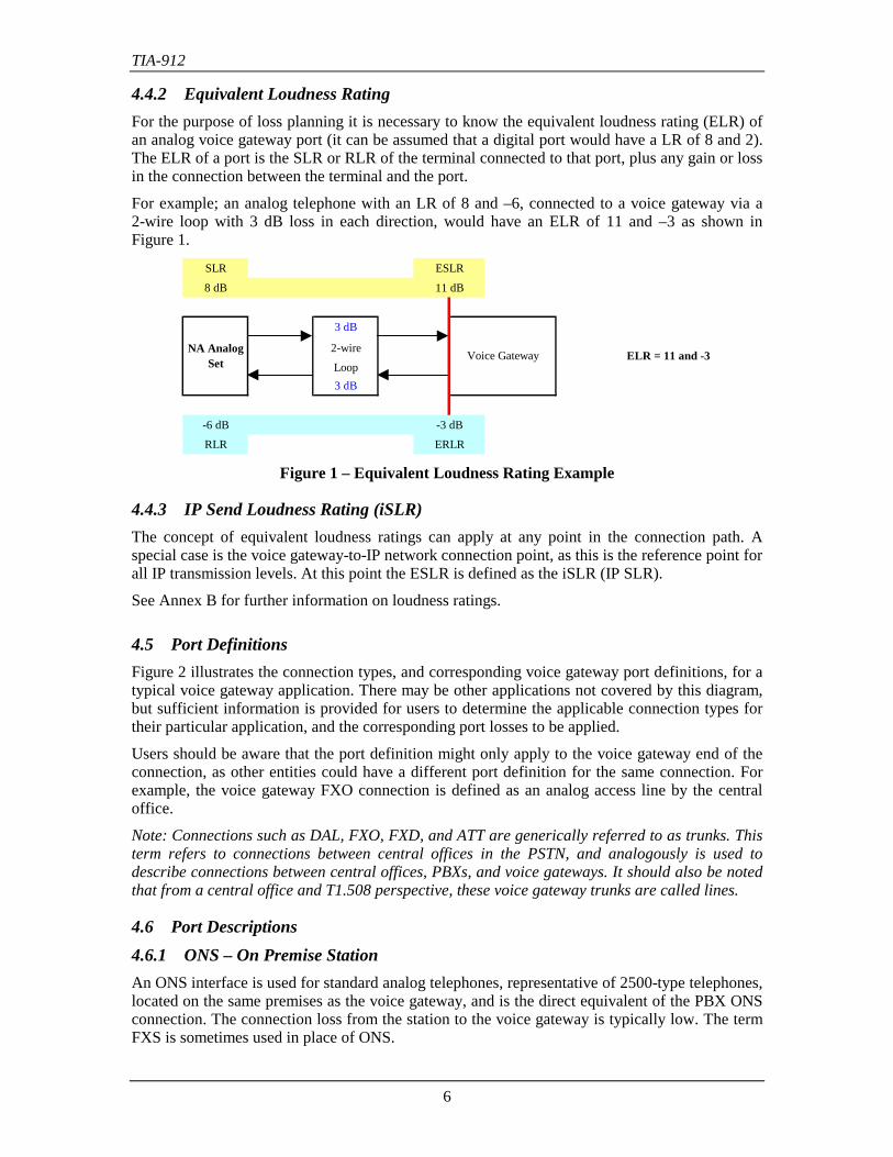
4.4.2 Equivalent Loudness RatingFor the purpose of loss planning it is necessary to know the equivalent loudness rating (ELR) ofan analog voice gateway port (it can be assumed that a digital port would have a LR of 8 and 2).The ELR of a port is the SLR or RLR of the terminal connected to that port, plus any gain or lossin the connection between the terminal and the port.
For example; an analog telephone with an LR of 8 and –6, connected to a voice gateway via a2-wire loop with 3 dB loss in each direction, would have an ELR of 11 and –3 as shown inFigure 1.
SLR ESLR
8 dB 11 dB
3 dB
2-wire
Loop3 dB
-6 dB -3 dB
RLR ERLR
NA Analog Set
Voice Gateway ELR = 11 and -3
Figure 1 – Equivalent Loudness Rating Example
4.4.3 IP Send Loudness Rating (iSLR)The concept of equivalent loudness ratings can apply at any point in the connection path. Aspecial case is the voice gateway-to-IP network connection point, as this is the reference point forall IP transmission levels. At this point the ESLR is defined as the iSLR (IP SLR).
See Annex B for further information on loudness ratings.
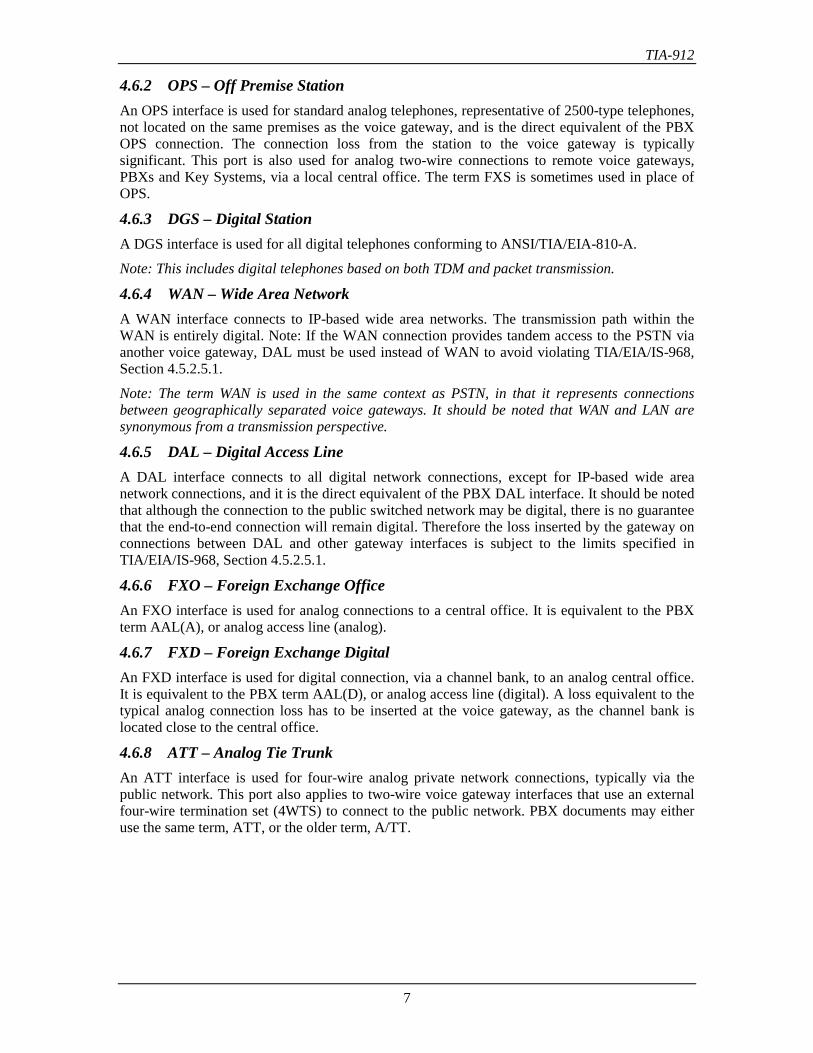
4.5 Port DefinitionsFigure 2 illustrates the connection types, and corresponding voice gateway port definitions, for atypical voice gateway application. There may be other applications not covered by this diagram,but sufficient information is provided for users to determine the applicable connection types fortheir particular application, and the corresponding port losses to be applied.
Users should be aware that the port definition might only apply to the voice gateway end of theconnection, as other entities could have a different port definition for the same connection. Forexample, the voice gateway FXO connection is defined as an analog access line by the centraloffice.
Note: Connections such as DAL, FXO, FXD, and ATT are generically referred to as trunks. Thisterm refers to connections between central offices in the PSTN, and analogously is used todescribe connections between central offices, PBXs, and voice gateways. It should also be notedthat from a central office and T1.508 perspective, these voice gateway trunks are called lines.
4.6 Port Descriptions4.6.1 ONS – On Premise StationAn ONS interface is used for standard analog telephones, representative of 2500-type telephones,located on the same premises as the voice gateway, and is the direct equivalent of the PBX ONSconnection. The connection loss from the station to the voice gateway is typically low. The termFXS is sometimes used in place of ONS.
TIA-912
7
4.6.2 OPS – Off Premise StationAn OPS interface is used for standard analog telephones, representative of 2500-type telephones,not located on the same premises as the voice gateway, and is the direct equivalent of the PBXOPS connection. The connection loss from the station to the voice gateway is typicallysignificant. This port is also used for analog two-wire connections to remote voice gateways,PBXs and Key Systems, via a local central office. The term FXS is sometimes used in place ofOPS.
4.6.3 DGS – Digital StationA DGS interface is used for all digital telephones conforming to ANSI/TIA/EIA-810-A.
Note: This includes digital telephones based on both TDM and packet transmission.
4.6.4 WAN – Wide Area NetworkA WAN interface connects to IP-based wide area networks. The transmission path within theWAN is entirely digital. Note: If the WAN connection provides tandem access to the PSTN viaanother voice gateway, DAL must be used instead of WAN to avoid violating TIA/EIA/IS-968,Section 4.5.2.5.1.
Note: The term WAN is used in the same context as PSTN, in that it represents connectionsbetween geographically separated voice gateways. It should be noted that WAN and LAN aresynonymous from a transmission perspective.
4.6.5 DAL – Digital Access LineA DAL interface connects to all digital network connections, except for IP-based wide areanetwork connections, and it is the direct equivalent of the PBX DAL interface. It should be notedthat although the connection to the public switched network may be digital, there is no guaranteethat the end-to-end connection will remain digital. Therefore the loss inserted by the gateway onconnections between DAL and other gateway interfaces is subject to the limits specified inTIA/EIA/IS-968, Section 4.5.2.5.1.
4.6.6 FXO – Foreign Exchange OfficeAn FXO interface is used for analog connections to a central office. It is equivalent to the PBXterm AAL(A), or analog access line (analog).
4.6.7 FXD – Foreign Exchange DigitalAn FXD interface is used for digital connection, via a channel bank, to an analog central office.It is equivalent to the PBX term AAL(D), or analog access line (digital). A loss equivalent to thetypical analog connection loss has to be inserted at the voice gateway, as the channel bank islocated close to the central office.
4.6.8 ATT – Analog Tie TrunkAn ATT interface is used for four-wire analog private network connections, typically via thepublic network. This port also applies to two-wire voice gateway interfaces that use an externalfour-wire termination set (4WTS) to connect to the public network. PBX documents may eitheruse the same term, ATT, or the older term, A/TT.
TIA-912
8
TelephonePorts
WAN
FXO
DAL
ATT
DGSONSOPS
FXD
DAL
DGS
DAL
WAN
OPS
ONS
VoiceGatewayDigital
CentralOffice
Analog orDigitalCentralOffice
ChannelBank
CentralOffice
PublicSwitchedNetwork
Ports
PrivateNetwork
Ports
IP NetworkPorts
VoiceGateway
Voice GatewayIP Connection
TDM Connection
Analog Connection
PBX
DAL
AAL(A)
ATT
WANDAL
WAN
VoiceGateway PortDesignation
Port DefinitionPBX or CO
PortDesignation
ONS Analog On Premise Station ONS
OPS Analog Off Premise Station - can be via an analog connection to a CO OPS
DGS Digital Station (telephone) DGS
WAN Wide Area Network (IP connection) -
DAL Digital Access Line - digital connection to a digital CO DAL
FXO Foreign Exchange Office - analog connection to analog or digital CO AAL(A)
FXD Foreign Exchange Digital - digital connection to an analog CO AAL(D)
ATT Analog Tie Trunk - private analog network connection to a gateway/PBX ATT
Figure 2 – Voice Gateway Connection Definitions
TIA-912
9
4.7 Abbreviations and AcronymsAbbreviations and acronyms, other than in common usage, are defined below.
AAL(A) Analog Access Line (Analog Interface at PBX)AAL(D) Analog Access Line (Digital Interface at PBX)A/D Analog-to-DigitalATT Analog Tie Trunk (latest acronym format)A/TT Analog Tie Trunk (previous acronym format)BRL Balance Return LossCO Central OfficeD/A Digital-to-AnalogDAL Digital Access LineDID Direct Inward DialingDGS Digital StationDMW Digital MilliwattELR Equivalent Loudness RatingERLR Equivalent Receive Loudness RatingESLR Equivalent Send Loudness RatingFDM Frequency Division MultiplexingFXD Foreign Exchange DigitalFXO Foreign Exchange OfficeFXS Foreign Exchange Station (see ONS & OPS)IP Internet ProtocoliSLR IP Send Loudness RatingLAN Local Area NetworkOLL Open Loop LossOLR Overall Loudness RatingONS On Premise StationOPS Off Premise StationPBX Private Branch ExchangePCM Pulse Code ModulationPSTN Public Switched Telephone NetworkRLR Receive Loudness RatingSLR Send Loudness RatingSPL Sound Pressure LevelTDM Time Division MultiplexWAN Wide Area NetworkZLP Zero Level Point
TIA-912
10
5 Preamble
5.1 GeneralDigital interfaces in the United States and Canada use µ-law encoding/decoding as defined inITU-T Recommendation G.711 (1988), ‘Pulse Code Modulation of Voice Frequencies’ [Ref. 8].
The transmission requirements contained in this standard are based on an industry-developedfixed loss and level plan. The requirements were developed with the objective of maintaining orimproving the quality of service for connections within existing and evolving communicationnetworks.
The requirements contained in this standard are based on current understanding of requiredperformance and on the capabilities of present technology. As technology evolves, or asperformance needs change, these requirements may become subject to change.
Note: For historical reasons the terms Stations, Sets, Telephones, and Terminals are usedinterchangeably in this standard.
5.2 Reference ImpedanceTransmission requirements contained here apply with station and trunk interfaces terminated in anominal impedance of 600 Ω, unless otherwise specified.
All measurements should be made at an equipment access point connected to the equipment byno more than 15 meters of cable, unless otherwise specified.
TIA-912
11
6 Loss and Level Plans
6.1 IntroductionA primary reason to establish a loss plan for voice communication systems is the desire to havethe received speech loudness at a comfortable listening level. This received loudness will dependupon the speech level of the talker, the transmit and receive efficiencies of the voice terminalsand the loss in the intervening network subsystems such as loops, trunks and switching systems.It is generally accepted among voice transmission experts that a connection with an overallloudness rating of 10 dB, which approximates a normal conversation between a talker andlistener spaced 1 meter apart, will provide a high degree of satisfaction for the majority of users.
Another important reason to establish a loss plan is to economically minimize the effect of echodue to signal reflections that are caused by impedance mismatching at 2-to-4 wire conversions inthe transmission path. In general, the insertion of loss in the transmission path reduces theimpairment due to echo, but increases the impairment due to noise. Another consideration thatmust be taken into account is that insertion of too much loss will adversely affect customersatisfaction with the received listening level. Therefore, rather than increasing loss indefinitelyon longer circuits, echo is controlled by the deployment of echo cancellers.
If digital telephones (i.e., conforming ANSI/TIA/EIA-810-A) are used at each end of theconnection, and if the entire end-to-end connection is over a digital based network, then the lossplan is very simple. The digital sets provide the desired overall loudness rating, hence the voicegateway would not insert any loss or gain in the voice channel.
In practice, however, many voice gateway connections will involve the public network in oneform or another, either by connections to the public switched network or by connections toprivate networks over public network facilities (e.g., tie trunks).
In general, connections through the public network can be analog either in whole or in part andinvolve2-to-4 wire conversions. The allocation of loss among the public network subsystems affects thenoise at the telephone receiver, the echo heard by the talker and the listener, the probability ofhearing other conversations, and the probability of causing interference on connections beingused by other customers. Also signals at too high a level can cause intermodulation distortion insome older carrier systems.
This standard recommends a loss and level plan for voice gateways that specifies the amount ofloss or gain to be inserted by the gateway when interfacing with the various elements of publicand private telecommunications networks. It is intended to be co-ordinated with the publicnetwork loss plan according to the principles of ANSI T1.508-1998 and it is intended to fullycomply with TIA/EIA/IS-968 Standard.
The loss and level plan consists of two parts:
• A full-channel plan that defines the port-to-port losses for all connections types. This issimilar to the PBX loss level plan as specified in PN-3-3673 (to be published asANSI/TIA/EIA-464-C) [Ref. 9], and ensures satisfactory interworking with the existingTDM based public and private networks
• A half-channel plan that defines the port-to-IP network and IP network-to-port losses. Thisplan is specific to IP telephony and will facilitate the interworking of national andinternational IP telephony networks.
TIA-912
12
6.2 Port-to-Port Loss AllocationThe allocation of the port-to-port loss to the send and receive ports directly influences theavailable dynamic range of the PCM coding scheme. This may lead to substantial impacts onspeech transmission quality as perceived by the user.
Care should be taken to ensure that excessive input gain or loss does not cause either PCMencoding overload, or a poor signal-to-noise ratio, at the zero-level point.
See Annex B.3 for further information on port-to-port loss allocation.
6.3 Digital PaddingDigital padding refers to the technique of implementing port-to-port losses by changing the levelof the digitally encoded voice. Digital padding should be avoided wherever possible, as it has thepotential to increase quantization distortion. Losses involving analog ports should beimplemented before encoding or after decoding.
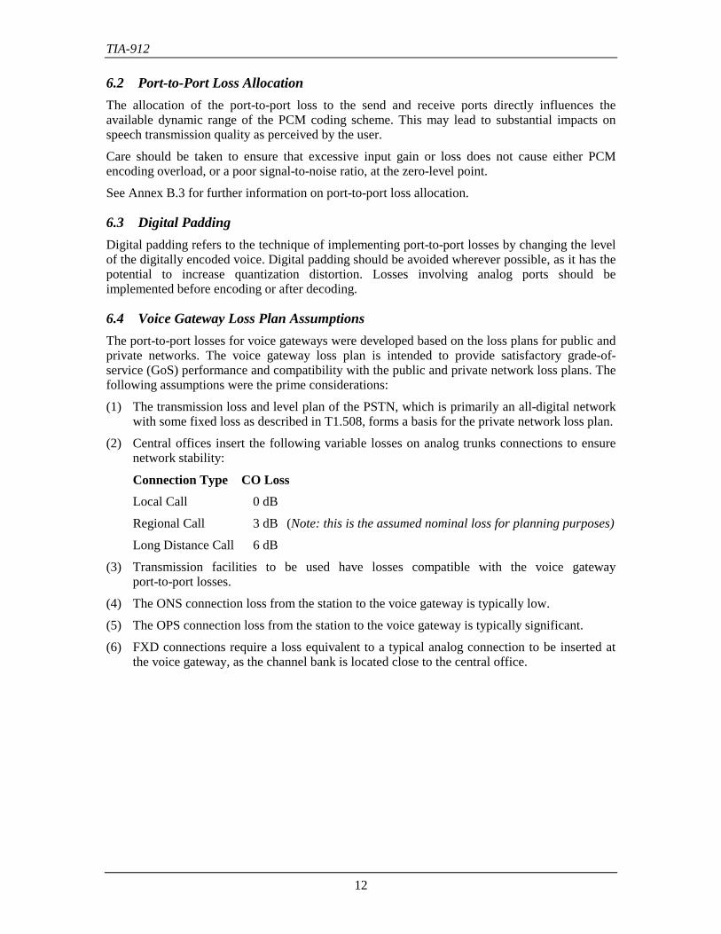
6.4 Voice Gateway Loss Plan AssumptionsThe port-to-port losses for voice gateways were developed based on the loss plans for public andprivate networks. The voice gateway loss plan is intended to provide satisfactory grade-of-service (GoS) performance and compatibility with the public and private network loss plans. Thefollowing assumptions were the prime considerations:
(1) The transmission loss and level plan of the PSTN, which is primarily an all-digital networkwith some fixed loss as described in T1.508, forms a basis for the private network loss plan.
(2) Central offices insert the following variable losses on analog trunks connections to ensurenetwork stability:
Connection Type CO LossLocal Call 0 dB
Regional Call 3 dB (Note: this is the assumed nominal loss for planning purposes)
Long Distance Call 6 dB
(3) Transmission facilities to be used have losses compatible with the voice gatewayport-to-port losses.
(4) The ONS connection loss from the station to the voice gateway is typically low.
(5) The OPS connection loss from the station to the voice gateway is typically significant.
(6) FXD connections require a loss equivalent to a typical analog connection to be inserted atthe voice gateway, as the channel bank is located close to the central office.
TIA-912
13
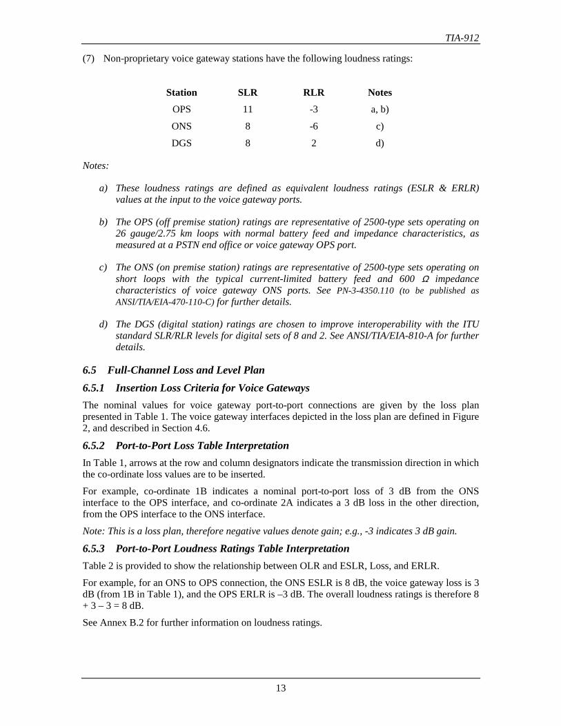
(7) Non-proprietary voice gateway stations have the following loudness ratings:
Station SLR RLR NotesOPS 11 -3 a, b)
ONS 8 -6 c)
DGS 8 2 d)
Notes:
a) These loudness ratings are defined as equivalent loudness ratings (ESLR & ERLR)values at the input to the voice gateway ports.
b) The OPS (off premise station) ratings are representative of 2500-type sets operating on26 gauge/2.75 km loops with normal battery feed and impedance characteristics, asmeasured at a PSTN end office or voice gateway OPS port.
c) The ONS (on premise station) ratings are representative of 2500-type sets operating onshort loops with the typical current-limited battery feed and 600 Ω impedancecharacteristics of voice gateway ONS ports. See PN-3-4350.110 (to be published asANSI/TIA/EIA-470-110-C) for further details.
d) The DGS (digital station) ratings are chosen to improve interoperability with the ITUstandard SLR/RLR levels for digital sets of 8 and 2. See ANSI/TIA/EIA-810-A for furtherdetails.
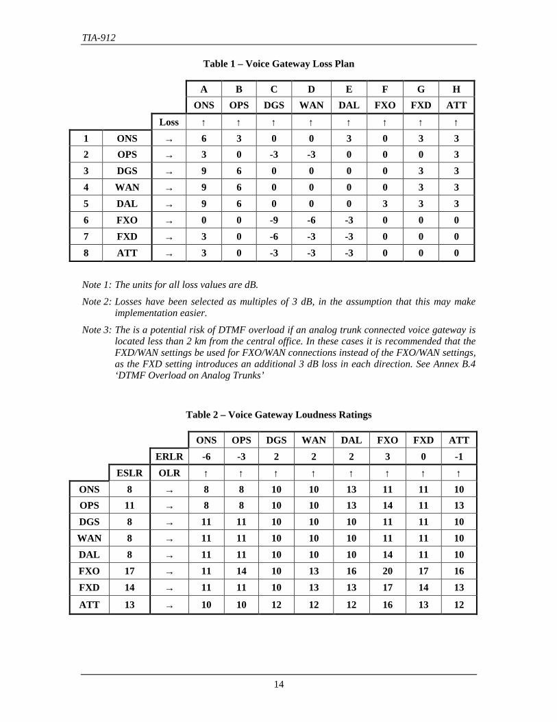
6.5 Full-Channel Loss and Level Plan6.5.1 Insertion Loss Criteria for Voice GatewaysThe nominal values for voice gateway port-to-port connections are given by the loss planpresented in Table 1. The voice gateway interfaces depicted in the loss plan are defined in Figure2, and described in Section 4.6.
6.5.2 Port-to-Port Loss Table InterpretationIn Table 1, arrows at the row and column designators indicate the transmission direction in whichthe co-ordinate loss values are to be inserted.
For example, co-ordinate 1B indicates a nominal port-to-port loss of 3 dB from the ONSinterface to the OPS interface, and co-ordinate 2A indicates a 3 dB loss in the other direction,from the OPS interface to the ONS interface.
Note: This is a loss plan, therefore negative values denote gain; e.g., -3 indicates 3 dB gain.
6.5.3 Port-to-Port Loudness Ratings Table InterpretationTable 2 is provided to show the relationship between OLR and ESLR, Loss, and ERLR.
For example, for an ONS to OPS connection, the ONS ESLR is 8 dB, the voice gateway loss is 3dB (from 1B in Table 1), and the OPS ERLR is –3 dB. The overall loudness ratings is therefore 8+ 3 – 3 = 8 dB.
See Annex B.2 for further information on loudness ratings.
TIA-912
14
Table 1 – Voice Gateway Loss Plan
A B C D E F G HONS OPS DGS WAN DAL FXO FXD ATT
Loss ↑ ↑ ↑ ↑ ↑ ↑ ↑ ↑1 ONS → 6 3 0 0 3 0 3 32 OPS → 3 0 -3 -3 0 0 0 33 DGS → 9 6 0 0 0 0 3 34 WAN → 9 6 0 0 0 0 3 35 DAL → 9 6 0 0 0 3 3 36 FXO → 0 0 -9 -6 -3 0 0 07 FXD → 3 0 -6 -3 -3 0 0 08 ATT → 3 0 -3 -3 -3 0 0 0
Note 1: The units for all loss values are dB.
Note 2: Losses have been selected as multiples of 3 dB, in the assumption that this may makeimplementation easier.
Note 3: The is a potential risk of DTMF overload if an analog trunk connected voice gateway islocated less than 2 km from the central office. In these cases it is recommended that theFXD/WAN settings be used for FXO/WAN connections instead of the FXO/WAN settings,as the FXD setting introduces an additional 3 dB loss in each direction. See Annex B.4‘DTMF Overload on Analog Trunks’
Table 2 – Voice Gateway Loudness Ratings
ONS OPS DGS WAN DAL FXO FXD ATTERLR -6 -3 2 2 2 3 0 -1
ESLR OLR ↑ ↑ ↑ ↑ ↑ ↑ ↑ ↑ONS 8 → 8 8 10 10 13 11 11 10OPS 11 → 8 8 10 10 13 14 11 13DGS 8 → 11 11 10 10 10 11 11 10WAN 8 → 11 11 10 10 10 11 11 10DAL 8 → 11 11 10 10 10 14 11 10FXO 17 → 11 14 10 13 16 20 17 16FXD 14 → 11 11 10 13 13 17 14 13
ATT 13 → 10 10 12 12 12 16 13 12
TIA-912
15
Note 1: The units for all loudness ratings (ESLR, ERLR, & OLR) are dB.
Note 2: The loudness ratings for the FXO and FXD ports include a nominal 3 dB CO loss.
Note 3: The loudness ratings for the ATT port include a nominal 2 dB trunk loss.
6.5.4 Voice Gateway Loss Ranges and TIA/EIA/IS-968 Requirements6.5.4.1 Recommended Loss RangesThe port-to-port losses in Table 1 are the recommended nominal values.
Although there are no mandatory loss ranges associated with these values, it is desirable that theaverage 1 kHz loss fall within ± 0.5 dB of the nominal loss values given in Table 1.
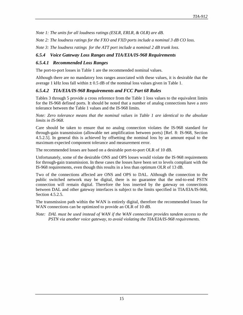
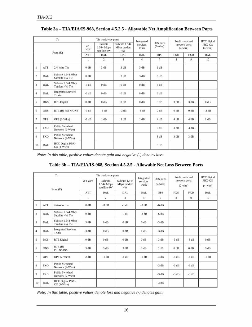
6.5.4.2 TIA/EIA/IS-968 Requirements and FCC Part 68 RulesTables 3 through 5 provide a cross reference from the Table 1 loss values to the equivalent limitsfor the IS-968 defined ports. It should be noted that a number of analog connections have a zerotolerance between the Table 1 values and the IS-968 limits.
Note: Zero tolerance means that the nominal values in Table 1 are identical to the absolutelimits in IS-968.
Care should be taken to ensure that no analog connection violates the IS-968 standard forthrough-gain transmission (allowable net amplification between ports) [Ref. 8: IS-968, Section4.5.2.5]. In general this is achieved by offsetting the nominal loss by an amount equal to themaximum expected component tolerance and measurement error.
The recommended losses are based on a desirable port-to-port OLR of 10 dB.
Unfortunately, some of the desirable ONS and OPS losses would violate the IS-968 requirementsfor through-gain transmission. In these cases the losses have been set to levels compliant with theIS-968 requirements, even though this results in a less than optimum OLR of 13 dB.
Two of the connections affected are ONS and OPS to DAL. Although the connection to thepublic switched network may be digital, there is no guarantee that the end-to-end PSTNconnection will remain digital. Therefore the loss inserted by the gateway on connectionsbetween DAL and other gateway interfaces is subject to the limits specified in TIA/EIA/IS-968,Section 4.5.2.5.
The transmission path within the WAN is entirely digital, therefore the recommended losses forWAN connections can be optimized to provide an OLR of 10 dB.
Note: DAL must be used instead of WAN if the WAN connection provides tandem access to thePSTN via another voice gateway, to avoid violating the TIA/EIA/IS-968 requirements.
TIA-912
16
Table 3a – TIA/EIA/IS-968, Section 4.5.2.5 - Allowable Net Amplification Between Ports
To Tie trunk type ports
2/4-wire
Subrate1.544 Mbpssatellite 4W
Subrate 1.544Mbps tandem
4W
Integratedservices
trunk
OPS ports(2-wire)
Public switchednetwork ports
(2-wire)
HCC digitalPBX-CO(4-wire)
ATT DAL DAL DAL OPS FXO FXD DALFrom (E)
1 2 3 4 7 8 9 10
1 ATT 2/4-Wire Tie 0 dB 3 dB 3 dB 3 dB 6 dB
2 DAL Subrate 1.544 MbpsSatellite 4W Tie 0 dB 3 dB 3 dB 6 dB
3 DAL Subrate 1.544 MbpsTandem 4W Tie -3 dB 0 dB 0 dB 0 dB 3 dB
4 DAL Integrated ServicesTrunk -3 dB 0 dB 0 dB 0 dB 3 dB
5 DGS RTE Digital 0 dB 0 dB 0 dB 0 dB 3 dB 3 dB 3 dB 0 dB
6 ONS RTE (B) PSTN/ONS -3 dB -3 dB -3 dB -3 dB 0 dB 0 dB 0 dB -3 dB
7 OPS OPS (2-Wire) -2 dB 1 dB 1 dB 1 dB 4 dB 4 dB 4 dB 1 dB
8 FXO Public SwitchedNetwork (2-Wire) 3 dB 3 dB 3 dB
9 FXD Public SwitchedNetwork (2-Wire) 3 dB 3 dB 3 dB
10 DAL HCC Digital PBX-CO (4-Wire) 3 dB
Note: In this table, positive values denote gain and negative (-) denotes loss.
Table 3b – TIA/EIA/IS-968, Section 4.5.2.5 - Allowable Net Loss Between Ports
To Tie trunk type ports
2/4-wire Subrate1.544 Mbpssatellite 4W
Subrate 1.544Mbps tandem
4W
Integratedservices
trunk
OPS ports
(2-wire)
Public switchednetwork ports
(2-wire)
HCC digitalPBX-CO
(4-wire)
ATT DAL DAL DAL OPS FXO FXD DALFrom (E)
1 2 3 4 7 8 9 10
1 ATT 2/4-Wire Tie 0 dB -3 dB -3 dB -3 dB -6 dB
2 DAL Subrate 1.544 MbpsSatellite 4W Tie 0 dB -3 dB -3 dB -6 dB
3 DAL Subrate 1.544 MbpsTandem 4W Tie 3 dB 0 dB 0 dB 0 dB -3 dB
4 DAL Integrated ServicesTrunk 3 dB 0 dB 0 dB 0 dB -3 dB
5 DGS RTE Digital 0 dB 0 dB 0 dB 0 dB -3 dB -3 dB -3 dB 0 dB
6 ONS RTE (B)PSTN/ONS 3 dB 3 dB 3 dB 3 dB 0 dB 0 dB 0 dB 3 dB
7 OPS OPS (2-Wire) 2 dB -1 dB -1 dB -1 dB -4 dB -4 dB -4 dB -1 dB
8 FXO Public SwitchedNetwork (2-Wire) -3 dB -3 dB -3 dB
9 FXD Public SwitchedNetwork (2-Wire) -3 dB -3 dB -3 dB
10 DAL HCC Digital PBX-CO (4-Wire) -3 dB
Note: In this table, positive values denote loss and negative (-) denotes gain.
TIA-912
17
Table 4 – Voice Gateway Recommended Net Loss Between Ports
To Tie trunk type ports
2/4-wire
Subrate1.544 Mbpssatellite 4W
Subrate 1.544Mbps tandem
4W
Integratedservices
trunk
OPS ports
(2-wire)
Public switchednetwork ports
(2-wire)
HCC digitalPBX-CO
(4-wire)
ATT DAL DAL DAL OPS FXO FXD DALFrom (E)
1 2 3 4 7 8 9 10
1 ATT 2/4-Wire Tie 0 dB -3 dB -3 dB -3 dB 0 dB 0 dB 0 dB -3 dB
2 DAL Subrate 1.544 MbpsSatellite 4W Tie 3 dB 0 dB 0 dB 0 dB -6 dB 3 dB 3 dB 0 dB
3 DAL Subrate 1.544 MbpsTandem 4W Tie 3 dB 0 dB 0 dB 0 dB 6 dB 3 dB 3 dB 0 dB
4 DAL Integrated ServicesTrunk 3 dB 0 dB 0 dB 0 dB 6 dB 3 dB 3 dB 0 dB
5 DGS RTE Digital 3 dB 0 dB 0 dB 0 dB 6 dB 0 dB 3 dB 0 dB
6 ONS RTE (B) PSTN/ONS 3 dB 3 dB 3 dB 3 dB 3 dB 0 dB 3 dB 3 dB
7 OPS OPS (2-Wire) 3 dB 0 dB 0 dB 0 dB 0 dB 0 dB 0 dB 0 dB
8 FXO Public SwitchedNetwork (2-Wire) 0 dB -3 dB -3 dB -3 dB 0 dB 0 dB 0 dB -3 dB
9 FXD Public SwitchedNetwork (2-Wire) 0 dB -3 dB -3 dB -3 dB 0 dB 0 dB 0 dB -3 dB
10 DAL HCC Digital PBX-CO (4-Wire) 3 dB 0 dB 0 dB 0 dB 6 dB 3 dB 3 dB 0 dB
Note: In this table, positive values denote loss and negative (-) denotes gain
Table 5 – Differences between TIA/EIA/IS-968, and Voice Gateway Port Losses
To Tie trunk type ports
2/4-wire
Subrate1.544 Mbpssatellite 4W
Subrate 1.544Mbps tandem
4W
Integratedservices
trunk
OPS ports
(2-wire)
Public switchednetwork ports
(2-wire)
HCC digitalPBX-CO
(4-wire)
ATT DAL DAL DAL OPS FXO FXD DALFrom (E)
1 2 3 4 7 8 9 10
1 ATT 2/4-Wire Tie 0 dB 0 dB 0 dB 0 dB 6 dB
2 DAL Subrate 1.544 MbpsSatellite 4W Tie 3 dB 3 dB 3 dB 12 dB
3 DAL Subrate 1.544 MbpsTandem 4W Tie 0 dB 0 dB 0 dB 0 dB 9 dB
4 DAL Integrated ServicesTrunk 0 dB 0 dB 0 dB 0 dB 9 dB
5 DGS RTE Digital 3 dB 0 dB 0 dB 0 dB 9 dB 3 dB 6 dB 0 dB
6 ONS RTE (B) PSTN/ONS 0 dB 0 dB 0 dB 0 dB 3 dB 0 dB 3 dB 0 dB
7 OPS OPS (2-Wire) 1 dB 1 dB 1 dB 1 dB 4 dB 4 dB 4 dB 1 dB
8 FXO Public SwitchedNetwork (2-Wire) 3 dB 3 dB 3 dB
9 FXD Public SwitchedNetwork (2-Wire) 3 dB 3 dB 3 dB
10 DAL HCC Digital PBX-CO (4-Wire) 9 dB
Note: In this table, positive values denote loss and negative (-) denotes gain
TIA-912
18
Notes:
1. The IS-968 limits in Table 3a and Table 3b are only provided as a convenience to usersof this standard. User should consult the latest IS-968 standard to ensure that they are incompliance.
2. The RTE(B) PSTN/ONS ports are for 2-wire on-premises station ports to separatelyregistered terminal equipment.
3. HCC Digital PBX-CO (4-wire) ports are for 4-wire 1.544 Mbps High Capacity Circuitdigital ports.
4. The numbers in the first column of each table are used in the first row of each table asreferences to the IS-968 port nomenclature
5. The shaded cells in Table 5 indicate analog connections with zero tolerance (see Section6.5.4.2).
TIA-912
19
6.6 Half-Channel Loss and Level Plan6.6.1 OverviewDeveloping a loss plan is generally a complex process, as the objective is to ensure a satisfactoryoverall loudness rating (OLR) for all connections types. To do this the loudness ratings of theend points (telephones), and the transmission loss between the end points, must be known foreach connection type.
This is a trivial exercise in a purely IP telephony environment, if one assumes that the end pointsare digital telephones with an LR of 8 and 2 (in line with ITU-T Recommendations), and that nogains or losses are introduced in the digital transmission path. In this case the OLR for any digitaltelephone-to-telephone connection world-wide is 10 dB, which is the ITU-T objective.
The complexity is introduced when the IP telephony network connects to analog telephones andtrunks. In this case the LR of the telephones, and the ELR of the trunks vary, although a loss-lessdigital transmission path can be maintained.
A half-channel loss plan for national and international IP telephony networks can beimplemented based on the premise that only the LRs and ELRs vary, and that the IP networkdoes not introduce any additional gain or loss.
Full-channel loss plans are still required for voice gateways, as voice gateways can also connectto existing analog and TDM based digital networks. These connections require losses to bedefined on a port-to-port basis for technical and regulatory reasons. A half-channel loss plan cantherefore be considered a sub-set of a full-channel loss plan that is only applicable to IP networkconnections.
6.6.2 ConceptThe basic concept in the half-channel loss plan is to normalize all transmit levels on an IPtelephony network to the same equivalent SLR (ESLR) - digital telephones provide the referenceSLR of 8 dB by definition. This is not an original concept, as it is the basis of the European dBrreference system. The move to standardize the North American digital telephone LRs to the ITU-T recommended levels makes this practical for IP telephony networks.
The same basic concept could be applied to the current non-IP PSTN and private networks, butexisting industry standards and IS-968 requirements would make it difficult to implement.
6.6.3 Principle of Operation• The originating entity will set the ESLR of the sending end point to 8 dB at the ingress to the
IP network. The ESLR at this point is defined as the iSLR.
• The terminating entity will adjust the loss at the egress from the IP network to achieve thedesired OLR at the receiving end point.
Note: The internationally recognized optimum OLR is 10 dB.
The advantage of this approach is that neither entity requires knowledge of the other, and lossplanning becomes a local issue.
TIA-912
20
6.6.4 ApplicabilityThis loss plan applies to all kind of IP based voice services, irrespective whether they provide:
• real time conversational telecommunication between human subjects, or
• listening-only telecommunication from a machine interface (stored speech) to a humansubject, or
• speaking-only telecommunication from a human subject to a machine interface;
The half-channel loss plan only applies to connections routed via IP networks; other voicegateway port-to-port connections are subject to the full-channel loss plan recommendations.
6.6.5 Reference Level PointThe reference or zero-level point for IP telephony is defined as the point where a connection ismade to a packet based network. This is equivalent to the zero-level point in standard TDMcircuit switched telephony.
Note: The reference level is defined as an iSLR of 8 dB, not a power level at 1004 Hz.
6.6.6 Recommended Loss RangesThe transmit and receive losses in Table 6 are the recommended nominal values.
Although there are no mandatory loss ranges associated with these values, it is desirable that theaverage 1 kHz loss fall within ± 0.5 dB of the nominal loss values given in Table 6.
6.6.7 IP Network LossesIt is critical for the operation of a half-channel loss plan that no gain or loss is inserted duringtransmission through the IP network. Any level changes due to transcoding for example, shouldbe less than 1 dB.
Note: Transcoding refers to the conversion from one voice coding algorithm to another, e.g.G.726 to G.729.
TIA-912
21
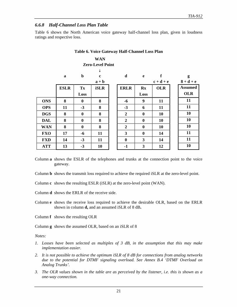
6.6.8 Half-Channel Loss Plan TableTable 6 shows the North American voice gateway half-channel loss plan, given in loudnessratings and respective loss.
Table 6. Voice Gateway Half-Channel Loss Plan
WANZero-Level Point
↓↓↓↓a b c d e f g
a + b c + d + e 8 + d + eESLR Tx iSLR ERLR Rx OLR Assumed
Loss Loss OLR
ONS 8 0 8 -6 9 11 11OPS 11 -3 8 -3 6 11 11DGS 8 0 8 2 0 10 10DAL 8 0 8 2 0 10 10WAN 8 0 8 2 0 10 10FXO 17 -6 11 3 0 14 11FXD 14 -3 11 0 3 14 11ATT 13 -3 10 -1 3 12 10
Column a shows the ESLR of the telephones and trunks at the connection point to the voicegateway.
Column b shows the transmit loss required to achieve the required iSLR at the zero-level point.
Column c shows the resulting ESLR (iSLR) at the zero-level point (WAN).
Column d shows the ERLR of the receive side.
Column e shows the receive loss required to achieve the desirable OLR, based on the ERLRshown in column d, and an assumed iSLR of 8 dB.
Column f shows the resulting OLR
Column g shows the assumed OLR, based on an iSLR of 8
Notes:
1. Losses have been selected as multiples of 3 dB, in the assumption that this may makeimplementation easier.
2. It is not possible to achieve the optimum iSLR of 8 dB for connections from analog networksdue to the potential for DTMF signaling overload. See Annex B.4 ‘DTMF Overload onAnalog Trunks’.
3. The OLR values shown in the table are as perceived by the listener, i.e. this is shown as aone-way connection.
TIA-912
22
6.6.9 Network StabilityThere is a potential for instability in connections involving 2 to 4 wire conversions if the openloop gain of the 4-wire loop approaches 0 dB.
Additional losses are inserted in public and private analog and digital TDM-based networks toensure they are unconditionally stable, and the resultant high OLRs are accepted for mixed 2-wire and 4-wire networks.
The use of this approach for a half-channel plan would result in unacceptable OLRs for someconnection types. Fortunately, the requirement for unconditional stability is not required in IPbased networks as a digital 4-wire loop will only oscillate when the hybrids at both ends of theloop are unterminated, and under these conditions the 4-wire loop would not be connected to anyanalog loops that could be affected by digital loop oscillation.
Notes:
1. Oscillation in a 4-wire loop has shown to cause harm to analog frequency divisionmultiplexing (FDM) transmission systems by affecting the FDM equipment's signal levelmanagement. There is no potential for such harm in purely digital systems.
2. See Annex B.5 for further information on open loop loss and network stability.
6.6.9.1 Stability LossITU-T Recommendation G.122 [Ref. 11], specifies the minimum stability loss for nationalsystems required to prevent instability on international calls. The stability loss of each nationalsystem represents one half of the open loop loss (OLL) of the 4-wire loops required to establishan international connection. This is equivalent to the voice gateway loss on either side of an IPnetwork connection. A stability loss of 6 dB at all frequencies between 200 and 3600 Hz willensure that the G.122 requirements are met. However, stability losses of between 6 dB and 0 dBwill formally comply with the present requirements of G.122.
This need not be a requirement for purely IP based connections for the reasons discussed above.
TIA-912
23
7 Loss Parameters
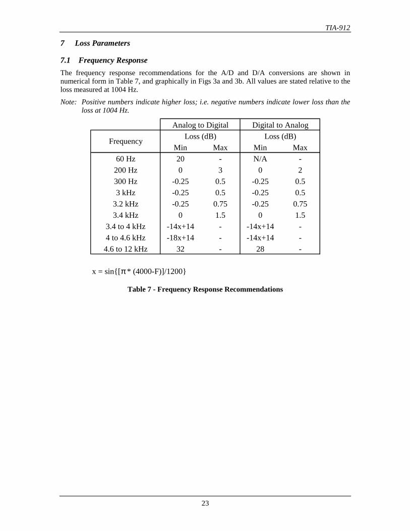
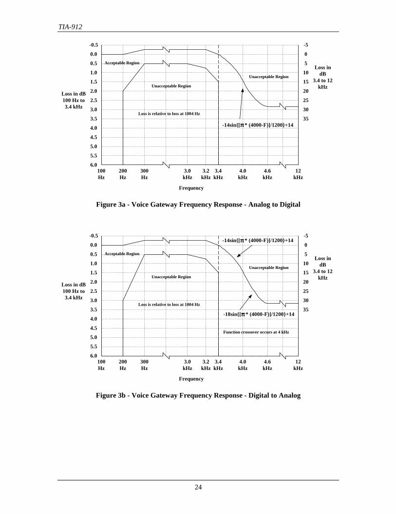
7.1 Frequency ResponseThe frequency response recommendations for the A/D and D/A conversions are shown innumerical form in Table 7, and graphically in Figs 3a and 3b. All values are stated relative to theloss measured at 1004 Hz.
Note: Positive numbers indicate higher loss; i.e. negative numbers indicate lower loss than theloss at 1004 Hz.
Analog to Digital Digital to AnalogLoss (dB) Loss (dB)
Min Max Min Max60 Hz 20 - N/A -200 Hz 0 3 0 2300 Hz -0.25 0.5 -0.25 0.53 kHz -0.25 0.5 -0.25 0.5
3.2 kHz -0.25 0.75 -0.25 0.753.4 kHz 0 1.5 0 1.5
3.4 to 4 kHz -14x+14 - -14x+14 -4 to 4.6 kHz -18x+14 - -14x+14 -4.6 to 12 kHz 32 - 28 -
x = sin[π * (4000-F)]/1200
Frequency
Table 7 - Frequency Response Recommendations
TIA-912
24
-0.5
0.0
0.5
1.0
1.5
2.0
2.5
3.0
3.5
4.0
4.5
5.0
5.5
6.0200Hz
300Hz
3.0kHz
3.2kHz
3.4kHz
4.0kHz
4.6kHz
12kHz
-5
0
5
10
15
20
25
30
35
Loss in dB100 Hz to3.4 kHz
Loss indB
3.4 to 12kHz
Frequency
-14sin[ππππ * (4000-F)]/1200+14
Unacceptable Region
Unacceptable Region
Acceptable Region
Loss is relative to loss at 1004 Hz
100Hz
Figure 3a - Voice Gateway Frequency Response - Analog to Digital
Loss indB
3.4 to 12kHz
-0.5
0.0
0.5
1.0
1.5
2.0
2.5
3.0
3.5
4.0
4.5
5.0
5.5
6.0200Hz
300Hz
3.0kHz
3.2kHz
3.4kHz
4.0kHz
4.6kHz
12kHz
-5
0
5
10
15
20
25
30
35
Frequency
Function crossover occurs at 4 kHz
Unacceptable Region
Unacceptable Region
Acceptable Region
Loss is relative to loss at 1004 Hz
Loss in dB100 Hz to3.4 kHz
100Hz
-14sin[ππππ * (4000-F)]/1200+14
-18sin[ππππ * (4000-F)]/1200+14
Figure 3b - Voice Gateway Frequency Response - Digital to Analog
TIA-912
25
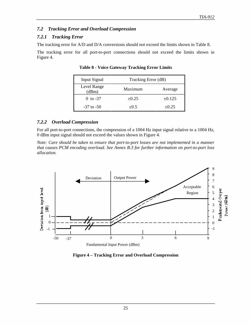
7.2 Tracking Error and Overload Compression7.2.1 Tracking ErrorThe tracking error for A/D and D/A conversions should not exceed the limits shown in Table 8.
The tracking error for all port-to-port connections should not exceed the limits shown inFigure 4.
Table 8 - Voice Gateway Tracking Error Limits
Input Signal Tracking Error (dB)Level Range
(dBm) Maximum Average
0 to -37 ±0.25 ±0.125
-37 to -50 ±0.5 ±0.25
7.2.2 Overload CompressionFor all port-to-port connections, the compression of a 1004 Hz input signal relative to a 1004 Hz,0 dBm input signal should not exceed the values shown in Figure 4.
Note: Care should be taken to ensure that port-to-port losses are not implemented in a mannerthat causes PCM encoding overload. See Annex B.3 for further information on port-to-port lossallocation.
Fundamental Input Power (dBm)
9876543210-1
10
-1
-50 -37 0 3 6 9
Deviation Output Power
AcceptableRegion
Figure 4 – Tracking Error and Overload Compression
TIA-912
26
8 Echo Control and Return LossEcho in transmission systems is due to reflections from impedance mismatches, and the mostcommon source of impedance mismatches in telephone networks is in the 2-to-4 wire converteror hybrid. The echo return loss is defined for two directions:
• 4-wire to 4-wire, which is a function of the hybrid balance
• 2-wire, which is a function of the 2-wire input impedance
Active echo control using echo cancellers or suppressers is beyond the scope of this section.
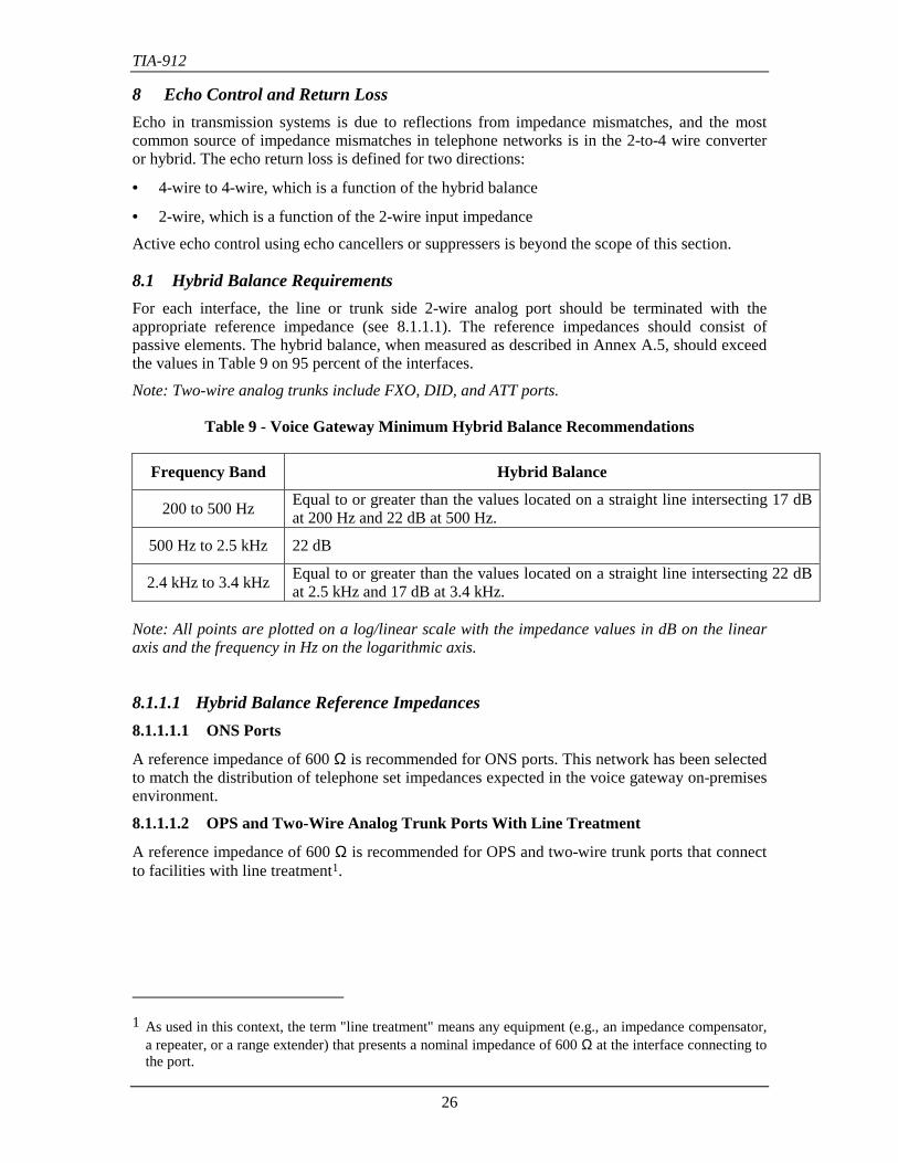
8.1 Hybrid Balance RequirementsFor each interface, the line or trunk side 2-wire analog port should be terminated with theappropriate reference impedance (see 8.1.1.1). The reference impedances should consist ofpassive elements. The hybrid balance, when measured as described in Annex A.5, should exceedthe values in Table 9 on 95 percent of the interfaces.
Note: Two-wire analog trunks include FXO, DID, and ATT ports.
Table 9 - Voice Gateway Minimum Hybrid Balance Recommendations
Frequency Band Hybrid Balance
200 to 500 Hz Equal to or greater than the values located on a straight line intersecting 17 dBat 200 Hz and 22 dB at 500 Hz.
500 Hz to 2.5 kHz 22 dB
2.4 kHz to 3.4 kHz Equal to or greater than the values located on a straight line intersecting 22 dBat 2.5 kHz and 17 dB at 3.4 kHz.
Note: All points are plotted on a log/linear scale with the impedance values in dB on the linearaxis and the frequency in Hz on the logarithmic axis.
8.1.1.1 Hybrid Balance Reference Impedances8.1.1.1.1 ONS Ports
A reference impedance of 600 Ω is recommended for ONS ports. This network has been selectedto match the distribution of telephone set impedances expected in the voice gateway on-premisesenvironment.
8.1.1.1.2 OPS and Two-Wire Analog Trunk Ports With Line Treatment
A reference impedance of 600 Ω is recommended for OPS and two-wire trunk ports that connectto facilities with line treatment1.
1 As used in this context, the term "line treatment" means any equipment (e.g., an impedance compensator,
a repeater, or a range extender) that presents a nominal impedance of 600 Ω at the interface connecting tothe port.
TIA-912
27
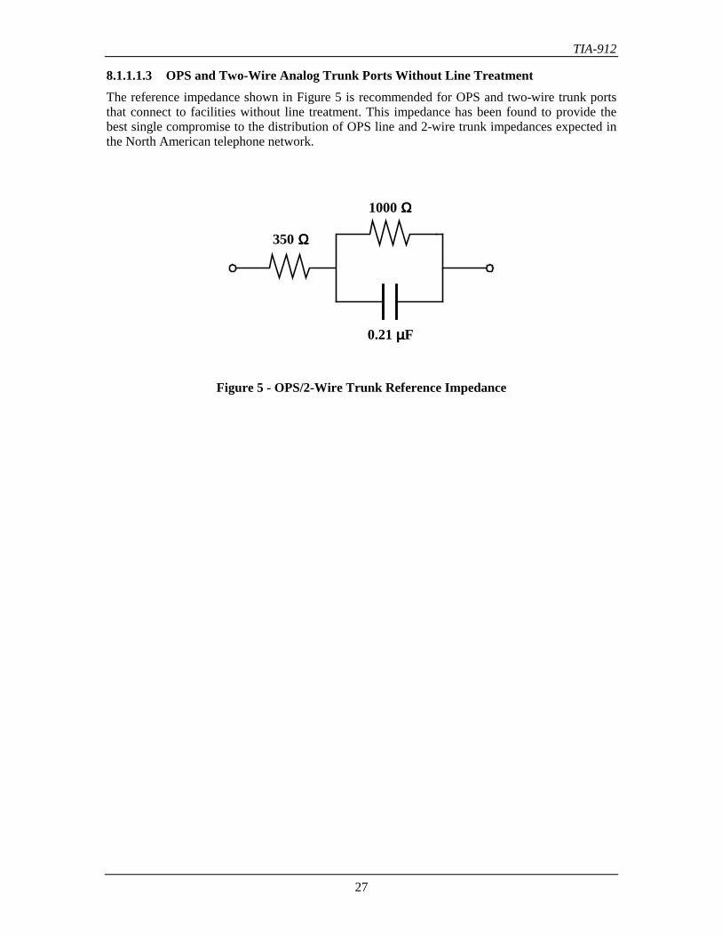
8.1.1.1.3 OPS and Two-Wire Analog Trunk Ports Without Line TreatmentThe reference impedance shown in Figure 5 is recommended for OPS and two-wire trunk portsthat connect to facilities without line treatment. This impedance has been found to provide thebest single compromise to the distribution of OPS line and 2-wire trunk impedances expected inthe North American telephone network.
350 ΩΩΩΩ
1000 ΩΩΩΩ
0.21 µµµµF
Figure 5 - OPS/2-Wire Trunk Reference Impedance
TIA-912
28
8.2 Input Impedance RequirementsRequirements are given only for paths through the switch for which the connecting port interface(the interface on the other side of the switch) is 4-wire. In this way, the measured results areindependent of any feedback resulting from imperfect balance of the far-end hybrids on 2-wireinterfaces. While such imperfect balance does influence the 2-wire interface input impedance andthe loss of the switch when it connects two 2-wire lines, the effects on in-service performance arecontrolled by having separate requirements for hybrid balance (Section 8.1) and insertion loss(Section 6).
The requirements for the input impedance are given in terms of a reference impedance (ZR) andminimum return loss. The return loss is defined in Annex C where the input impedance isdenoted by ZI and reference impedance by ZR. The return loss is a function of frequency, andincreases without limit as the input impedance approaches the reference impedance.
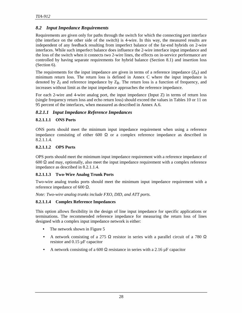
For each 2-wire and 4-wire analog port, the input impedance (Input Z) in terms of return loss(single frequency return loss and echo return loss) should exceed the values in Tables 10 or 11 on95 percent of the interfaces, when measured as described in Annex A.6.
8.2.1.1 Input Impedance Reference Impedances8.2.1.1.1 ONS Ports
ONS ports should meet the minimum input impedance requirement when using a referenceimpedance consisting of either 600 Ω or a complex reference impedance as described in8.2.1.1.4.
8.2.1.1.2 OPS Ports
OPS ports should meet the minimum input impedance requirement with a reference impedance of600 Ω and may, optionally, also meet the input impedance requirement with a complex referenceimpedance as described in 8.2.1.1.4.
8.2.1.1.3 Two-Wire Analog Trunk PortsTwo-wire analog trunks ports should meet the minimum input impedance requirement with areference impedance of 600 Ω.
Note: Two-wire analog trunks include FXO, DID, and ATT ports.
8.2.1.1.4 Complex Reference Impedances
This option allows flexibility in the design of line input impedance for specific applications orterminations. The recommended reference impedance for measuring the return loss of linesdesigned with a complex input impedance network is either:
• The network shown in Figure 5
• A network consisting of a 275 Ω resistor in series with a parallel circuit of a 780 Ωresistor and 0.15 µF capacitor
• A network consisting of a 600 Ω resistance in series with a 2.16 µF capacitor
TIA-912
29
Table 10 - Voice Gateway Return Loss Recommendations for 600 ΩΩΩΩ ZR
Return Loss
Frequency Band Minimum Desirable
200 to 500 HzEqual to or greater than the valueslocated on a straight line intersecting14 dB at 200 Hz and 22 dB at 500 Hz.
Equal to or greater than the valueslocated on a straight line intersecting14 dB at 200 Hz and 26 dB at 500 Hz.
500 Hz to 2.5 kHz 22 dB 26 dB
2.4 kHz to 3.4 kHz
Equal to or greater than the valueslocated on a straight line intersecting22 dB at 2.5 kHz and 14 dB at3.4 kHz.
Equal to or greater than the valueslocated on a straight line intersecting26 dB at 2.5 kHz and 14 dB at3.4 kHz.
Table 11 - Voice Gateway Return Loss Recommendations for Complex ZR
Return Loss
Frequency Band Minimum Desirable
200 to 500 HzEqual to or greater than the valueslocated on a straight line intersecting14 dB at 200 Hz and 22 dB at 500 Hz.
-
500 Hz to 2.5 kHz 22 dB -
2.4 kHz to 3.4 kHz
Equal to or greater than the valueslocated on a straight line intersecting22 dB at 2.5 kHz and 14 dB at3.4 kHz.
-
Note: All points are plotted on a log/linear scale with the impedance values in dB on the linearaxis and the frequency in Hz on the logarithmic axis.
TIA-912
30
9 Noise and Distortion Impairments
9.1 Idle-Channel NoiseIdle-channel noise is the short-term, average, absolute noise power measured with a flat or C-message weighting in the absence of signal.
Compliance with the idle-channel noise requirements should be determined as described inAnnex A.7.
9.1.1 3 kHz Flat Noise
(1) The 3 kHz flat weighted noise should not exceed 35 dBrn on 50 percent of theconnections.
(2) The 3 kHz flat weighted noise should not exceed 39 dBrn on 95 percent of theconnections.
For interface transmission levels other than 0 dB, the 3 kHz flat weighted noise requirementshould be shifted by a value that corresponds to the difference between the transmission level atthat interface and 0 dB.
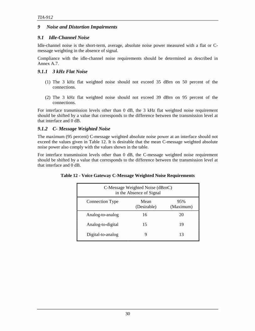
9.1.2 C- Message Weighted NoiseThe maximum (95 percent) C-message weighted absolute noise power at an interface should notexceed the values given in Table 12. It is desirable that the mean C-message weighted absolutenoise power also comply with the values shown in the table.
For interface transmission levels other than 0 dB, the C-message weighted noise requirementshould be shifted by a value that corresponds to the difference between the transmission level atthat interface and 0 dB.
Table 12 - Voice Gateway C-Message Weighted Noise Requirements
C-Message Weighted Noise (dBrnC)in the Absence of Signal
Connection Type Mean(Desirable)
95%(Maximum)
Analog-to-analog 16 20
Analog-to-digital 15 19
Digital-to-analog 9 13
TIA-912
31
9.2 Longitudinal BalanceThe voice gateway interfaces that are subject to longitudinal balance requirements includeloop/ground start CO/FXO trunks, reverse battery (DID) trunks, OPS lines, and digital servicetrunks.
9.2.1 Longitudinal-to-Metallic Balance
(1) Definition.
The longitudinal-to-metallic balance is defined as:
Longitudinal Balance (dB) = 20 log|Vs / Vm|.
where Vs is the disturbing longitudinal rms voltage, and Vm the resulting metallic rms voltage ofthe same frequency.
The longitudinal-to-metallic balance recommendations only apply to analog ports. A lowconversion of longitudinal into metallic noise is required to limit noise on the talking circuit.
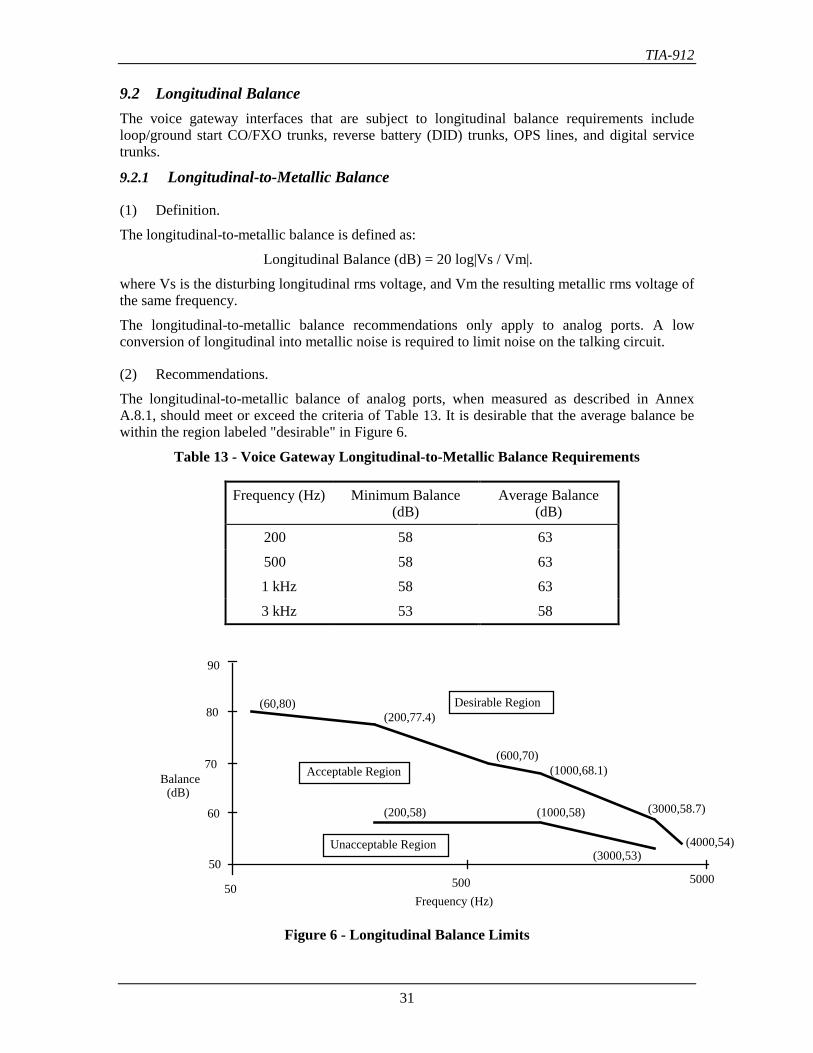
(2) Recommendations.
The longitudinal-to-metallic balance of analog ports, when measured as described in AnnexA.8.1, should meet or exceed the criteria of Table 13. It is desirable that the average balance bewithin the region labeled "desirable" in Figure 6.
Table 13 - Voice Gateway Longitudinal-to-Metallic Balance Requirements
Frequency (Hz) Minimum Balance(dB)
Average Balance(dB)
200 58 63
500 58 63
1 kHz 58 63
3 kHz 53 58
Frequency (Hz)
Balance(dB)
50
60
70
80
90
50 500 5000
(3000,53)
(1000,58)(200,58)
(4000,54)
(3000,58.7)
(1000,68.1)(600,70)
(200,77.4)(60,80) Desirable Region
Acceptable Region
Unacceptable Region
Figure 6 - Longitudinal Balance Limits
TIA-912
32
9.2.2 Metallic-to-Longitudinal (Transverse Balance) Balance9.2.2.1 DefinitionThe transverse balance is defined as:
Transverse Balance (dB) = 20 log |Vm / Vs|
where Vs is the longitudinal rms voltage produced across a longitudinal termination Z1, and Vmis the metallic rms voltage across the tip-and-ring interface terminals of the voice gateway.
Transverse balance (metallic-to-longitudinal balance) is specified in IS-968 to ensure that ametallic signal is not converted into a longitudinal signal that could cause excessive noise inother pairs of a multi-pair cable.
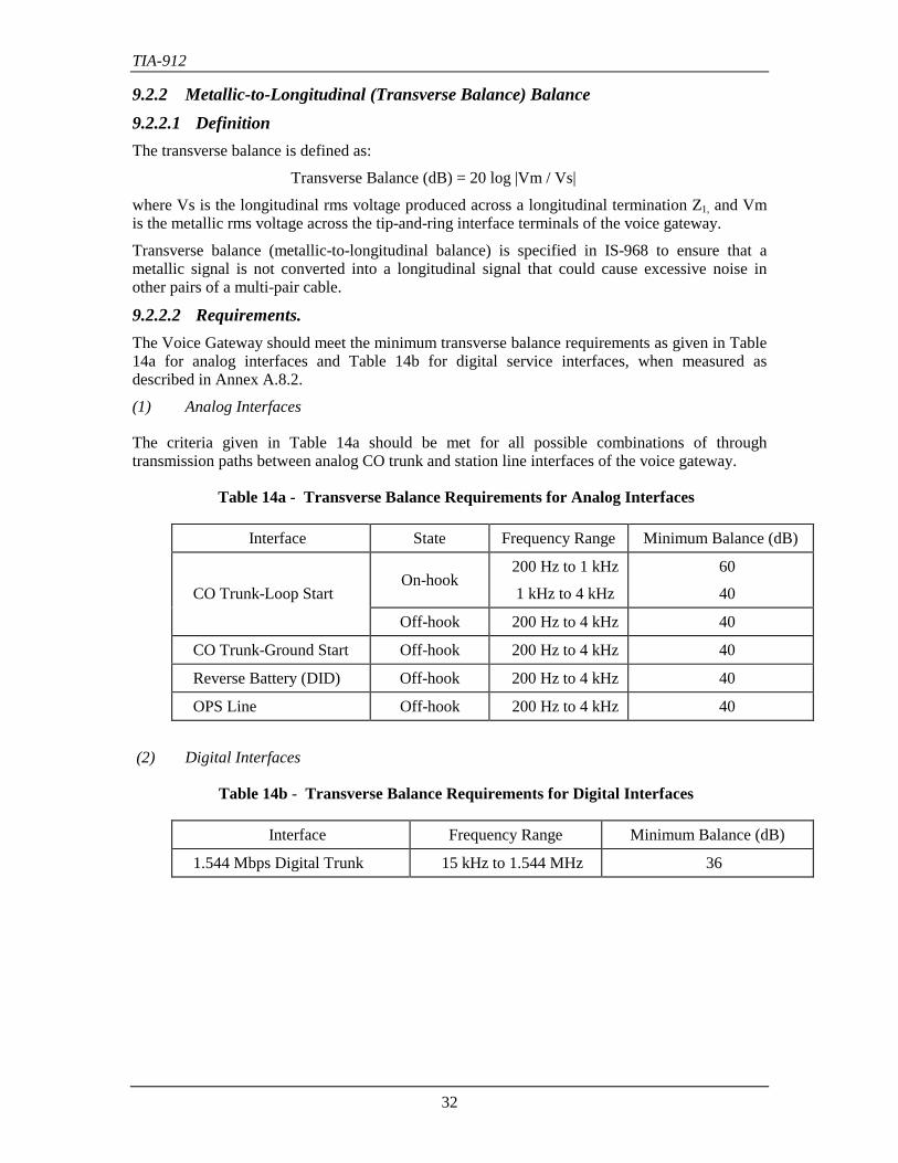
9.2.2.2 Requirements.The Voice Gateway should meet the minimum transverse balance requirements as given in Table14a for analog interfaces and Table 14b for digital service interfaces, when measured asdescribed in Annex A.8.2.
(1) Analog Interfaces
The criteria given in Table 14a should be met for all possible combinations of throughtransmission paths between analog CO trunk and station line interfaces of the voice gateway.
Table 14a - Transverse Balance Requirements for Analog Interfaces
Interface State Frequency Range Minimum Balance (dB)
CO Trunk-Loop StartOn-hook
200 Hz to 1 kHz
1 kHz to 4 kHz
60
40
Off-hook 200 Hz to 4 kHz 40
CO Trunk-Ground Start Off-hook 200 Hz to 4 kHz 40
Reverse Battery (DID) Off-hook 200 Hz to 4 kHz 40
OPS Line Off-hook 200 Hz to 4 kHz 40
(2) Digital Interfaces
Table 14b - Transverse Balance Requirements for Digital Interfaces
Interface Frequency Range Minimum Balance (dB)
1.544 Mbps Digital Trunk 15 kHz to 1.544 MHz 36
TIA-912
33
9.3 Crosstalk9.3.1 RequirementThe crosstalk coupling loss for every port-to-port connection, over the 200 to 3400 Hz frequencyband, should comply with the following criteria:
(1) The crosstalk coupling loss between any established connection through the voice gatewayand at least 95 percent of all other through connections should be at least 75 dB, and it isdesirable that this loss be at least 80 dB.
(2) The crosstalk coupling loss between any established connection through the voice gatewayand any other through connection should be at least 70 dB.
Compliance with the crosstalk coupling loss recommendations should be determined as describedin Annex A.9.
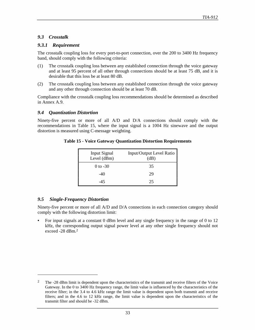
9.4 Quantization DistortionNinety-five percent or more of all A/D and D/A connections should comply with therecommendations in Table 15, where the input signal is a 1004 Hz sinewave and the outputdistortion is measured using C-message weighting.
Table 15 - Voice Gateway Quantization Distortion Requirements
Input Signal Input/Output Level RatioLevel (dBm) (dB)
0 to -30 35
-40 29
-45 25
9.5 Single-Frequency DistortionNinety-five percent or more of all A/D and D/A connections in each connection category shouldcomply with the following distortion limit:
• For input signals at a constant 0 dBm level and any single frequency in the range of 0 to 12kHz, the corresponding output signal power level at any other single frequency should notexceed -28 dBm.2
2 The -28 dBm limit is dependent upon the characteristics of the transmit and receive filters of the Voice
Gateway. In the 0 to 3400 Hz frequency range, the limit value is influenced by the characteristics of thereceive filter; in the 3.4 to 4.6 kHz range the limit value is dependent upon both transmit and receivefilters; and in the 4.6 to 12 kHz range, the limit value is dependent upon the characteristics of thetransmit filter and should be -32 dBm.
TIA-912
34
10 Other ImpairmentsThe following requirements apply to voice gateways intended to pass voiceband data. Thefollowing requirements are given, in addition to the voice requirements, to verify that the voicegateway will function in a manner that will not be seen as an impairment to the performance ofvoiceband data modems.
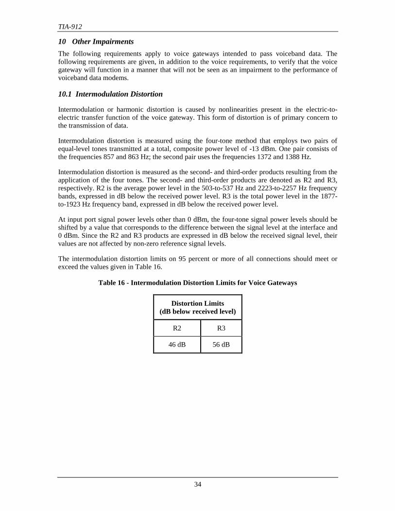
10.1 Intermodulation Distortion
Intermodulation or harmonic distortion is caused by nonlinearities present in the electric-to-electric transfer function of the voice gateway. This form of distortion is of primary concern tothe transmission of data.
Intermodulation distortion is measured using the four-tone method that employs two pairs ofequal-level tones transmitted at a total, composite power level of -13 dBm. One pair consists ofthe frequencies 857 and 863 Hz; the second pair uses the frequencies 1372 and 1388 Hz.
Intermodulation distortion is measured as the second- and third-order products resulting from theapplication of the four tones. The second- and third-order products are denoted as R2 and R3,respectively. R2 is the average power level in the 503-to-537 Hz and 2223-to-2257 Hz frequencybands, expressed in dB below the received power level. R3 is the total power level in the 1877-to-1923 Hz frequency band, expressed in dB below the received power level.
At input port signal power levels other than 0 dBm, the four-tone signal power levels should beshifted by a value that corresponds to the difference between the signal level at the interface and0 dBm. Since the R2 and R3 products are expressed in dB below the received signal level, theirvalues are not affected by non-zero reference signal levels.
The intermodulation distortion limits on 95 percent or more of all connections should meet orexceed the values given in Table 16.
Table 16 - Intermodulation Distortion Limits for Voice Gateways
Distortion Limits(dB below received level)
R2 R3
46 dB 56 dB
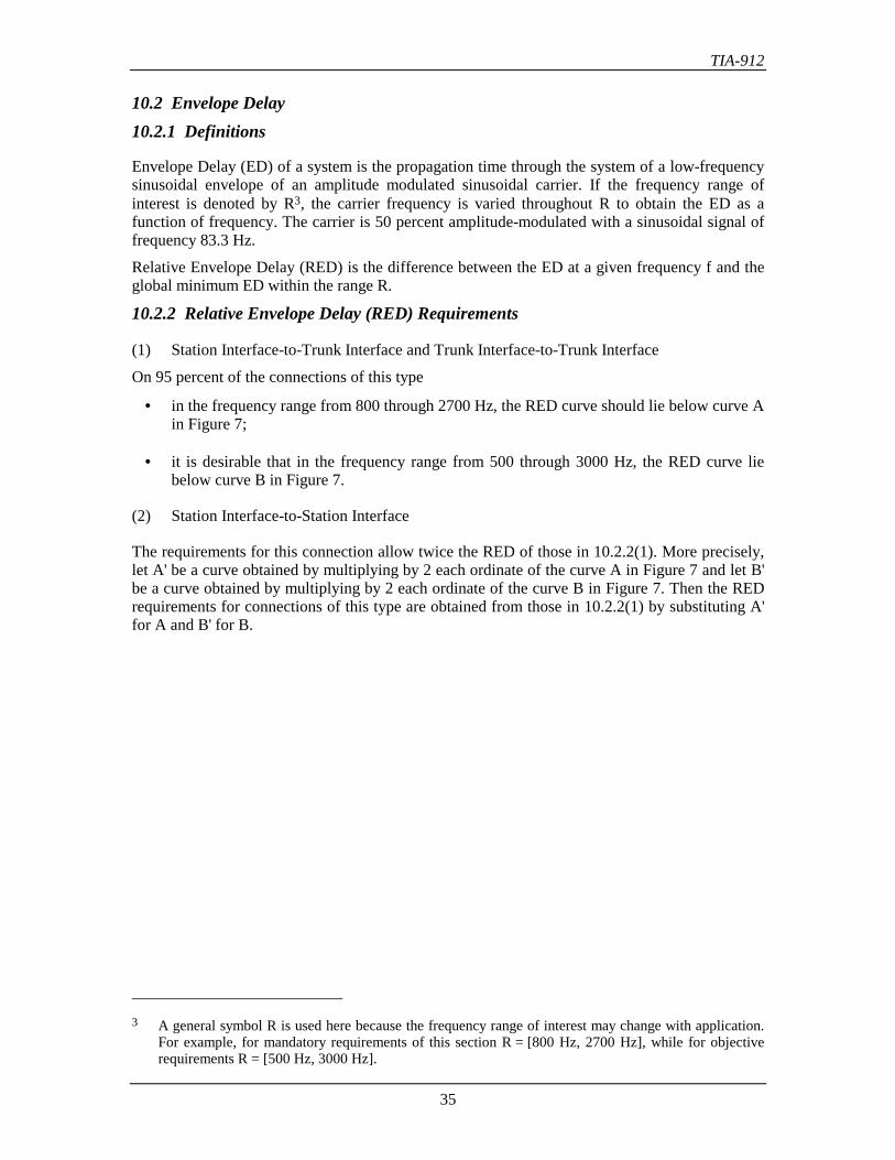
TIA-912
35
10.2 Envelope Delay10.2.1 Definitions
Envelope Delay (ED) of a system is the propagation time through the system of a low-frequencysinusoidal envelope of an amplitude modulated sinusoidal carrier. If the frequency range ofinterest is denoted by R3, the carrier frequency is varied throughout R to obtain the ED as afunction of frequency. The carrier is 50 percent amplitude-modulated with a sinusoidal signal offrequency 83.3 Hz.
Relative Envelope Delay (RED) is the difference between the ED at a given frequency f and theglobal minimum ED within the range R.
10.2.2 Relative Envelope Delay (RED) Requirements
(1) Station Interface-to-Trunk Interface and Trunk Interface-to-Trunk Interface
On 95 percent of the connections of this type
• in the frequency range from 800 through 2700 Hz, the RED curve should lie below curve Ain Figure 7;
• it is desirable that in the frequency range from 500 through 3000 Hz, the RED curve liebelow curve B in Figure 7.
(2) Station Interface-to-Station Interface
The requirements for this connection allow twice the RED of those in 10.2.2(1). More precisely,let A' be a curve obtained by multiplying by 2 each ordinate of the curve A in Figure 7 and let B'be a curve obtained by multiplying by 2 each ordinate of the curve B in Figure 7. Then the REDrequirements for connections of this type are obtained from those in 10.2.2(1) by substituting A'for A and B' for B.
3 A general symbol R is used here because the frequency range of interest may change with application.
For example, for mandatory requirements of this section R = [800 Hz, 2700 Hz], while for objectiverequirements R = [500 Hz, 3000 Hz].
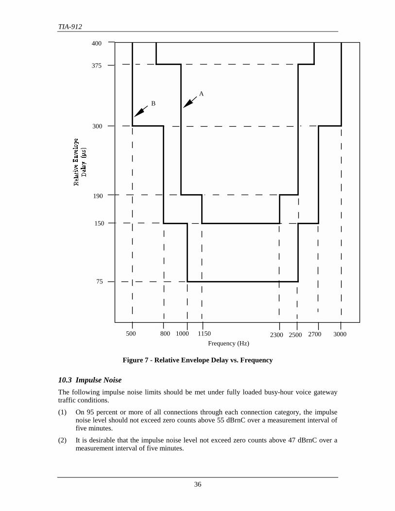
TIA-912
36
400
375
300
190
150
75
500 800 1000 1150 2300 2500 2700 3000
AB
Frequency (Hz)
Figure 7 - Relative Envelope Delay vs. Frequency
10.3 Impulse NoiseThe following impulse noise limits should be met under fully loaded busy-hour voice gatewaytraffic conditions.
(1) On 95 percent or more of all connections through each connection category, the impulsenoise level should not exceed zero counts above 55 dBrnC over a measurement interval offive minutes.
(2) It is desirable that the impulse noise level not exceed zero counts above 47 dBrnC over ameasurement interval of five minutes.
TIA-912
37
10.4 JitterJitter on a port-to-port connection should not exceed 2 degrees within the 4-to-300 Hz frequencyband.
10.5 Gain HitThere should be no more than one gain hit per hour at a threshold level of 3 dB. If there is morethan one hit in a period of 1 hour, the subsequent hour should have zero hits. A gain hit is anincidental modulation resulting in a rapid positive or negative shift of signal gain lasting for aperiod of at least 4 ms.
10.6 Phase HitThere should be no more than one phase hit per hour exceeding a threshold of 20 degrees. Ifthere is more than one phase hit in a period of 1 hour, the subsequent hour should have zero hits.A phase hit is an incidental modulation resulting in a rapid positive or negative shift of signalphase lasting for a period of at least 4 ms.
10.7 DropoutThere should be no more than one dropout per hour exceeding a threshold of 6 dB. If there ismore than one dropout in a period of 1 hour, the subsequent hour should have zero dropouts. Adropout is a negative gain hit lasting a period of at least 10 ms.
10.8 Peak-to-Average Power RatioThe voice gateway should pass a signal, analog port-to-analog port, with a peak-to-average powerratio (P/AR) of 95.
P/AR = 100 x ((2Ep/EFWA)-1), where Ep is the normalized peak and EFWA is the normalizedfull rectified average of the envelope.
TIA-912
38
11 Signal LevelsThe voice gateway should comply with TIA/EIA/IS-968, Section 4.5, for the following signallevel limitations:
(1) In-band Signal Power Limits(a) Internal Signal Sources Not Intended for Network Control Signaling(b) Internal Signal Sources Intended Primarily for Network Control Signaling(c) Through Transmission(d) Idle State Circuit Stability for Tie Trunks(e) Metallic Signal Power at Frequencies in the range 3995 to 4005 Hz(f) Longitudinal Voltage in the 100- to 4000 Hz Frequency Range
(2) Out-of-Band Signal Voltage Limits(a) Metallic Voltage(b) Longitudinal Voltage
The above listed signal limitations should apply to:
(1) Analog Trunk interfaces (ground start, loop start, DID)(2) OPS Lines(3) Analog Tie Trunks(4) Digital Trunk interface (ground start, loop start, DID, ISDN Basic Rate and Primary
Rate) with encoded analog contents(5) Digital OPS Lines with encoded analog contents(6) Digital Tie Trunk interface with encoded analog contents
TIA-912
39
Annex A (informative) - Measurement GuidelinesThis annex is informative only and is not part of this standard
A.1. Gain Ripples in the Measurement PathIn any digital voice gateway, connections from a 2-wire analog port to a 2-wire analog port willconstitute a closed-loop feedback system. The feedback signal will cause ripples in the netthrough-gain response of a 2-wire to 2-wire connection. If care is not exercised, the ripple effectwill influence measurement accuracy. The following two techniques for avoiding rippleinfluence on measurements are suggested:
(1) Perform test measurements on a 2-wire to 4-wire basis. This approach eliminates thefeedback signal. Where appropriate, the requirements contained in these sections have beendivided into transmit and receive portions to facilitate this approach. It will be necessary toemploy a digital test meter and designated digital test sequences for these types of measurements.
Alternatively, a half-channel test, in which the two directions of transmission are terminatedwithin the switching fabric, may be used (see Section 8).
(2) Maintain a high-quality impedance match at each 2-wire to 4-wire interface to minimizethe feedback signal. This approach requires use of a test impedance that closely matches thehybrid balance impedance. To satisfactorily reduce the ripple caused by the feedback signal, ahybrid balance of 25 dB (or greater) should be maintained at each 2-wire to 4-wire interface inthe test connection.
A.2. Transmission Level TranslationEach of the requirements in this section has been written with respect to the zero-level point inthe switch. A 0 dBm0 signal at this point will decode to 0 dBm, or 1 mW in 600 Ω.
In many cases, the interface level will be different from the zero-level point due to the lossesintroduced to meet the loss plan. In these cases (unless otherwise stated) the appropriate interfaceloss should be included when determining compliance with the requirements.
See Annex B.6 for further information on zero-level points, the definition of 0 dBm0, andtransmission level translation.
A.3. Dial-up Port for Trunk TestingTo avoid the gain variations that can occur among different terminations, it is recommended thata special dial-up port be designated for trunk testing. However, it should be recognized that evenwhen using a single termination to test all trunks, consideration for gain tracking variation in thedial-up port must be included. The gain tracking variation will occur because different trunklosses will cause different signal levels at the dial-up port. The tracking variation will be limitedby the tracking error requirements at the various interfaces (see Section 7.4)
A.4. Digital Test Port AvailabilityFor circuit and line-up purposes, the voice gateway should have provisions for a test port, orequivalent, that enables zero-level point testing at a digital interface.
TIA-912
40
A.5. Hybrid BalanceThe measurement technique described in this section is applicable to line or trunk units thatconnect to 2-wire analog interfaces.
Examples of test arrangements for testing for compliance with hybrid balance requirements areshown in Figure A1 (full-channel method) and Figure A2 (half-channel method).
When using the full-channel method (Figure A1), the impedance of the signal generator, ZG, andthe signal detector, ZO, should match the impedance of the 4-wire port.
When using the digital half-channel method (Figure A2), the detector and generator should beequivalent digital instruments.
An analog half-channel method may also be used (similar to Figure A2). The tests can be madevia a line or trunk unit access point, or a path can be set up between the line or trunk unit and a 4-wire interface. If test access is from an analog interface, the generator impedance (ZG) and thedetector impedance (ZO) should match the interface impedance.
Note: A Return Loss Measuring Set (RLMS), conforming to ANSI/IEEE Standard 743-1995[Ref. 11] is recommended as the signal generator and detector shown in Figure A1 (or anequivalent digital instrument for Figure A2).
The steps for measuring the hybrid balance are :
1. Measure the 2-to-4 wire and 4-to-2 wire loss through the hybrid at 1004 Hz, with the 2-wireport terminated in the appropriate reference impedance.
2. Measure the 4-wire to 4-wire loss (echo return loss) through the hybrid at frequencies over therange of 200 to 3400 Hz, with the 2-wire port terminated in the appropriate referenceimpedance.
3. Subtract the sum of the losses determined in Step 1 from the values measured in Step 2 todetermine the hybrid balance over the specified frequency range.
A.6. Input ImpedanceExamples of test arrangements for testing compliance with the input impedance requirements areshown in Figures A3 through A6.
The steps for measuring the input impedance are :
1. Terminate the 4-wire analog ports not under test in impedances (ZT) that match the interfaceimpedances.
2. Terminate the return loss measuring set with the reference impedance (ZR) for the port undertest, as defined in 8.2.1.
3. Measure the single frequency return loss (SFRL) and echo return loss (ERL) over the range200 to 3400 Hz to determine compliance with the return loss requirements in Table 10 (600Ω ZR) or Table 11 (Complex ZR). See Annex C for the SFRL and ERL definitions.
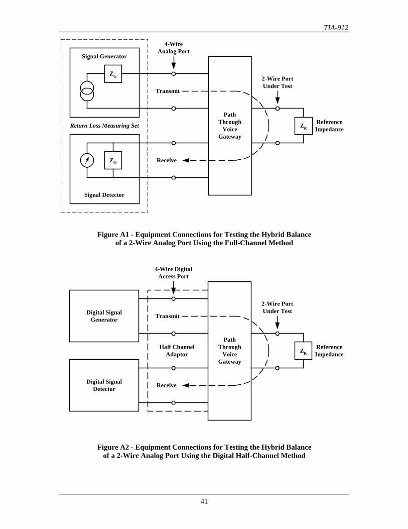
TIA-912
41
Return Loss Measuring Set
PathThrough
VoiceGateway
Transmit
Receive
2-Wire PortUnder Test
ReferenceImpedance
4-WireAnalog Port
ZR
ZO
ZG
Signal Generator
Signal Detector
Figure A1 - Equipment Connections for Testing the Hybrid Balanceof a 2-Wire Analog Port Using the Full-Channel Method
PathThrough
VoiceGateway
Transmit
Receive
2-Wire PortUnder Test
ReferenceImpedance
4-Wire DigitalAccess Port
ZR
Digital SignalGenerator
Digital SignalDetector
Half ChannelAdaptor
Figure A2 - Equipment Connections for Testing the Hybrid Balanceof a 2-Wire Analog Port Using the Digital Half-Channel Method
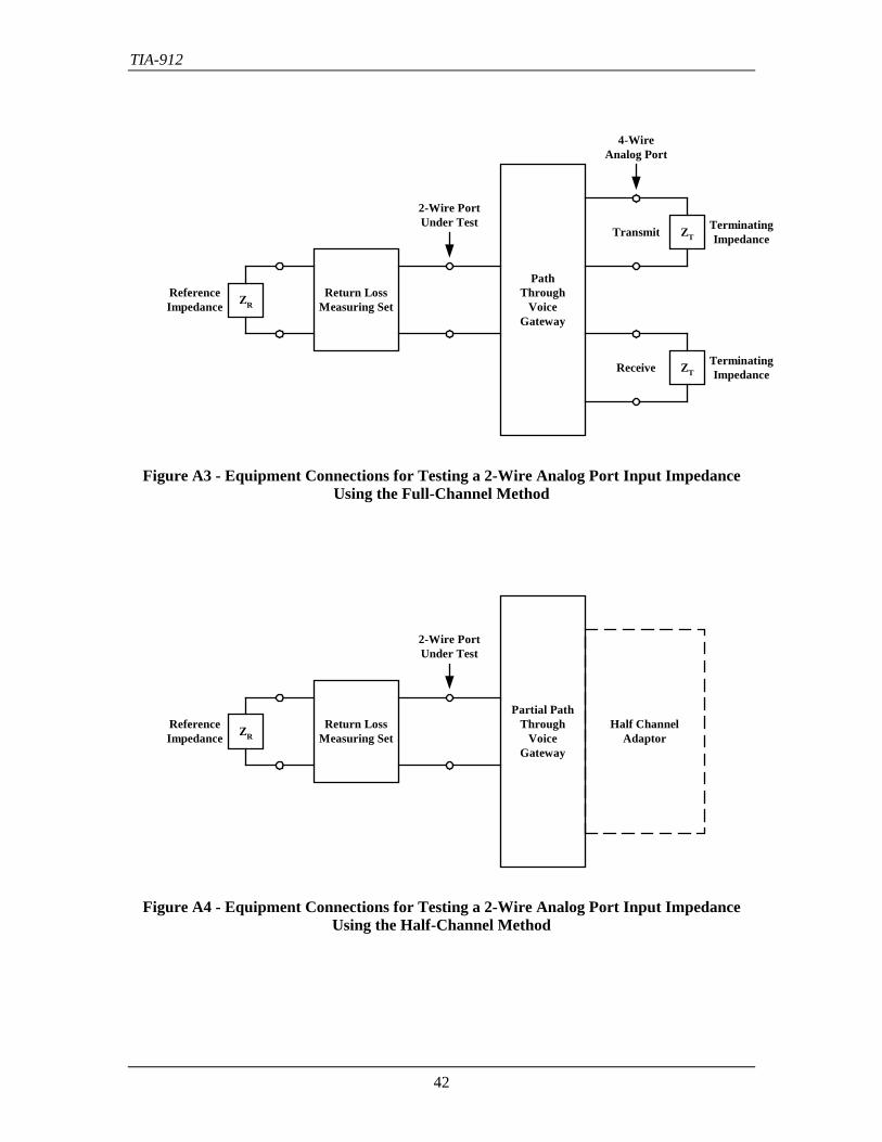
TIA-912
42
Figure A3 - Equipment Connections for Testing a 2-Wire Analog Port Input ImpedanceUsing the Full-Channel Method
Figure A4 - Equipment Connections for Testing a 2-Wire Analog Port Input ImpedanceUsing the Half-Channel Method
Return LossMeasuring Set
Partial PathThrough
VoiceGateway
2-Wire PortUnder Test
ReferenceImpedance
Half ChannelAdaptorZR
Return LossMeasuring Set
PathThrough
VoiceGateway
Transmit
Receive
2-Wire PortUnder Test
ReferenceImpedance
TerminatingImpedance
TerminatingImpedance
4-WireAnalog Port
ZR
ZT
ZT
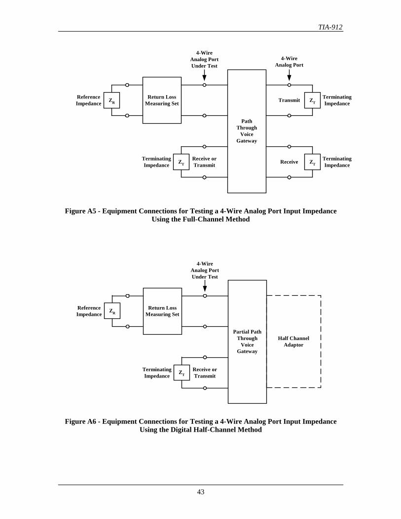
TIA-912
43
Figure A5 - Equipment Connections for Testing a 4-Wire Analog Port Input ImpedanceUsing the Full-Channel Method
Figure A6 - Equipment Connections for Testing a 4-Wire Analog Port Input ImpedanceUsing the Digital Half-Channel Method
Partial PathThrough
VoiceGateway
Half ChannelAdaptor
Return LossMeasuring Set
4-WireAnalog PortUnder Test
ReferenceImpedance
Receive orTransmit
TerminatingImpedance
ZR
ZT
Return LossMeasuring Set
PathThrough
VoiceGateway
Transmit
Receive
4-WireAnalog PortUnder Test
ReferenceImpedance
TerminatingImpedance
TerminatingImpedance
4-WireAnalog Port
Receive orTransmit
TerminatingImpedance
ZR
ZT
ZT
ZT
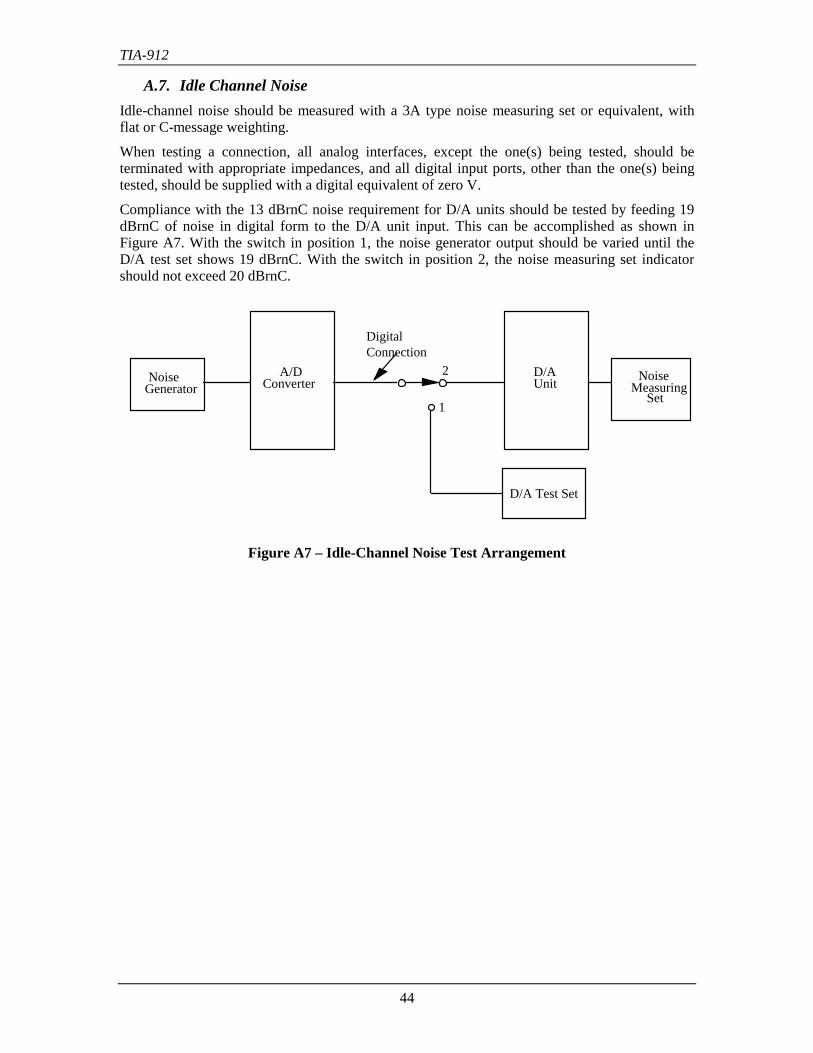
TIA-912
44
A.7. Idle Channel NoiseIdle-channel noise should be measured with a 3A type noise measuring set or equivalent, withflat or C-message weighting.
When testing a connection, all analog interfaces, except the one(s) being tested, should beterminated with appropriate impedances, and all digital input ports, other than the one(s) beingtested, should be supplied with a digital equivalent of zero V.
Compliance with the 13 dBrnC noise requirement for D/A units should be tested by feeding 19dBrnC of noise in digital form to the D/A unit input. This can be accomplished as shown inFigure A7. With the switch in position 1, the noise generator output should be varied until theD/A test set shows 19 dBrnC. With the switch in position 2, the noise measuring set indicatorshould not exceed 20 dBrnC.
Noise Noise Measuring
Set
A/DConverter
D/AUnit
D/A Test Set
2
1
Digital Connection
Generator
Figure A7 – Idle-Channel Noise Test Arrangement
TIA-912
45
A.8. Longitudinal BalanceA.8.1 Longitudinal to Metallic Balance
The test procedure is detailed in ANSI/IEEE Standard 455-1992 [Ref. 12]. It is recommendedthat a frequency selective voltmeter is used. These tests should be conducted for only the off-hook state of the voice gateway.
A.8.2. Metallic to Longitudinal (Transverse) BalanceThe test procedure is outlined in the IS-968 standard and TIA/EIA TSB31-B the Part 68Rationale and Measurement Guidelines [Ref. 13]. Test circuits that satisfies the stated conditionsare shown in Figure A8 (Analog), and Figure A9 (Digital).
A metallic voltage should be applied from a balanced source with a metallic impedance Z0 atsuitable points over the frequency range f1 to f2, and set so that Vm equals E volts when atermination of Z0 is substituted for the voice gateway. The Z0 termination should then be replacedby the voice gateway and the longitudinal voltage Vs measured.
The frequency ranges and terminations for each service are defined in Table A1.
The conditions for performing these measurements on the voice gateway are:
(a) All values of dc loop current that the interface under test is capable of drawing whenconnected to the IS-968 loop simulator circuit for CO trunk interfaces, or the IS-968line simulator circuit for OPS and DID interfaces.
(b) All reasonable conditions of application of earth ground to the voice gateway undertest.
(c) All CO trunk or OPS interfaces not under test, terminated in their appropriate networksor in some cases grounded (see (h), below).
(d) All other than CO and OPS interfaces terminated in circuits appropriate to thoseinterfaces.
(e) Both on-hook and off-hook states applicable to the interface under test.
(f) Impedances of the balance test circuit should be (Z0) metallic and (Z1) longitudinal, asdefined in Table A1.
(g) Termination of all interfaces not being measured should be follows:
CO trunk Figure A10OPS, off-hook Figure A11OPS, on-hook (unterminated).
(h) For station line interfaces designed to isolate longitudinal currents introduced throughfully-protected premises wiring or through non-registered equipment, or both, either ofthe T or R conductors of all ONS station interfaces should be grounded, and the T or Rconductors should be both:
(i) Terminated in an impedance that will reflect correct impedance to the network portto which it is connected for through transmission (see Figure A12).
(ii) Unterminated.
(i) For station line interfaces not designed to isolate longitudinal currents introducedthrough unprotected premises wiring, the T&R conductors of all ONS stationinterfaces should be both:
(i) Terminated in a metallic resistance of 600 Ω and a longitudinal resistance of 150 Ω(see Figure A11).
(ii) Unterminated.
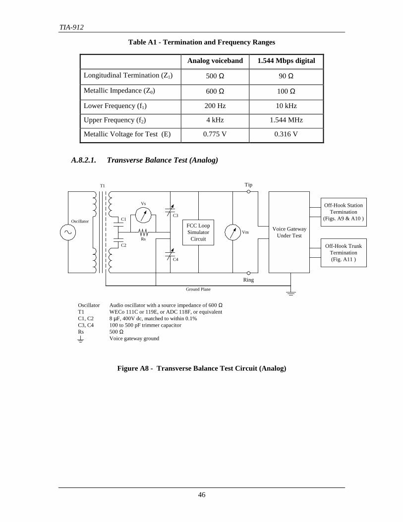
TIA-912
46
Table A1 - Termination and Frequency Ranges
Analog voiceband 1.544 Mbps digital
Longitudinal Termination (Z1) 500 Ω 90 Ω
Metallic Impedance (Z0) 600 Ω 100 Ω
Lower Frequency (f1) 200 Hz 10 kHz
Upper Frequency (f2) 4 kHz 1.544 MHz
Metallic Voltage for Test (E) 0.775 V 0.316 V
A.8.2.1. Transverse Balance Test (Analog)
FCC LoopSimulator
Circuit
Voice GatewayUnder Test
Off-Hook StationTermination
(Figs. A9 & A10 )
Off-Hook TrunkTermination(Fig. A11 )
Tip
Ring
Oscillator
Vs
C1
C2Rs
C3
C4
Vm
T1
Ground Plane
Oscillator Audio oscillator with a source impedance of 600 ΩT1 WECo 111C or 119E, or ADC 118F, or equivalentC1, C2 8 µF, 400V dc, matched to within 0.1%C3, C4 100 to 500 pF trimmer capacitorRs 500 Ω
Voice gateway ground
Figure A8 - Transverse Balance Test Circuit (Analog)
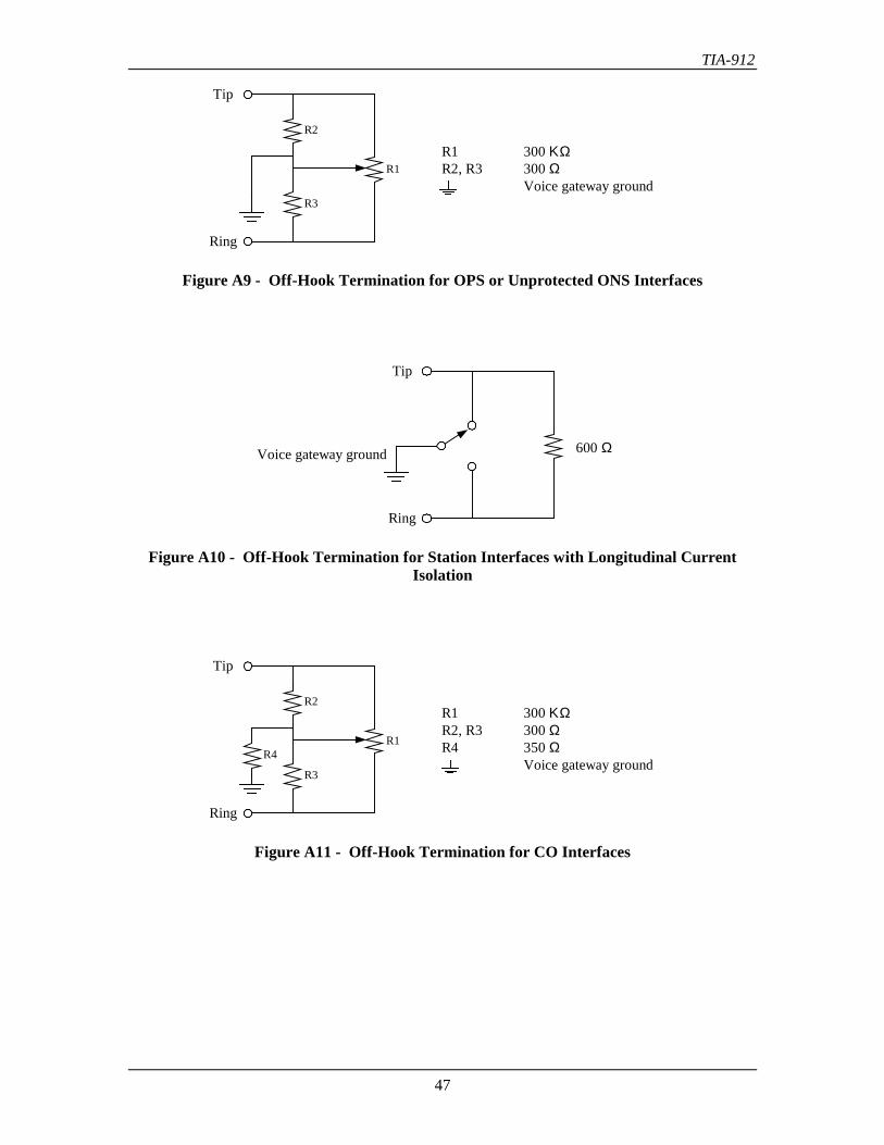
TIA-912
47
Ring
Tip
R2
R3
R1R1 300 ΚΩR2, R3 300 Ω
Voice gateway ground
Figure A9 - Off-Hook Termination for OPS or Unprotected ONS Interfaces
Ring
Tip
Voice gateway ground 600 Ω
Figure A10 - Off-Hook Termination for Station Interfaces with Longitudinal CurrentIsolation
Ring
Tip
R2
R3
R4R1
R1 300 ΚΩR2, R3 300 ΩR4 350 Ω
Voice gateway ground
Figure A11 - Off-Hook Termination for CO Interfaces
TIA-912
48
Notes:
1. Vm should not be measured at the same time that Vs is measured.
2. Use trimmer capacitors C3 and C4 to balance the test circuit to 20 dB greater balance thanthe equipment standard for all frequencies specified, with a 600 Ω resistor substituted forthe voice gateway.
3. R1 of the off-hook terminations shall be adjusted to obtain a balance of ≥ 60 dB from 200 Hzto 1 kHz and ≥ 40 dB from 1 kHz to 4 kHz.
4. Exposed conductive surfaces on the exterior of the voice gateway should be connected to theground plane.
5. Use the TIA/EIA/IS-968 loop simulator for CO trunks with resistor R1 of the simulatordisconnected.
6. Use the TIA/EIA/IS-968 line simulator for OPS lines and DID trunks with resistor R1 of thesimulator disconnected.
7. Use the off-hook termination shown in Figure A10 for station interfaces with longitudinalcurrent isolation as described in Section A.8.2 (h).

TIA-912
49
A.8.2.2. Transverse Balance Test (Digital)
Voice GatewayUnder Test
Tip
Ring
TrackingGenerator
Vs
RL
C2
C1
T1
Ground Plane
Tracking Generator Tracking generator with a source impedance of 100 ΩT1 1:1 100 Ω wide-band transformerC1 20 pF differential capacitorC2 3 pF composition RF capacitorRL 90 Ω non-inductive precision resistorRCal 100 Ω non-inductive precision resistor
Voice gateway ground
SpectrumAnalyzer
Vm
SpectrumAnalyzer
RCal
S3 S2
S1
C2
Figure A12 - Transverse Balance Test Circuit (Digital)
Notes:
1. Capacitor C1 should be a dual-stator, air-variable RF capacitor, that maintains a constantcapacitance between stators, while providing a variable capacitance from either stator toground.
2. Capacitor C2 may be placed on either line of the test set (as shown), to obtain properbalancing of the bridge.
TIA-912
50
A.9. Crosstalk Coupling Loss
A test arrangement for measuring crosstalk coupling loss is shown in Figure A13. It may bedesirable when making crosstalk measurements, that a 10 dBrnC level of noise exist at the inputinterface of the disturbed connection.
Test Procedure(1) Vary resistors R1 through R4 (referring to Figure A13) to obtain the full loop current
ranges specified for the voice gateway interfaces under test, as measured by the 0-200mA dc meters.
(2) Calibrate the 600 Ω oscillator at 1004 Hz to a level of 0 dBm into a separate 600 Ωresistor. Then, reconnect the oscillator, without changing its level, into the test circuit asshown in Figure A13.
(3) Take readings on both wave analyzers in the disturbed connections:
(a) Select the higher power reading and subtract it from the calibrated level of the oscillator.The result is value A.
(b) Interchange the oscillator and load resistor R5 and repeat (a). The result is value B.
(c) Interchange the disturbing and disturbed connections and repeat (a) and (b). The resultsare values C and D.
(d) Select the lowest power value of A, B, C, and D. This is the value of crosstalk couplingloss for that pair of connections.
(4) Repeat (3) for all frequencies over the range 200 to 3400 Hz.
(5) Repeat (4) for all loop current values according to (1).
(6) Repeat (5) for all pairs of connections of the voice gateway.
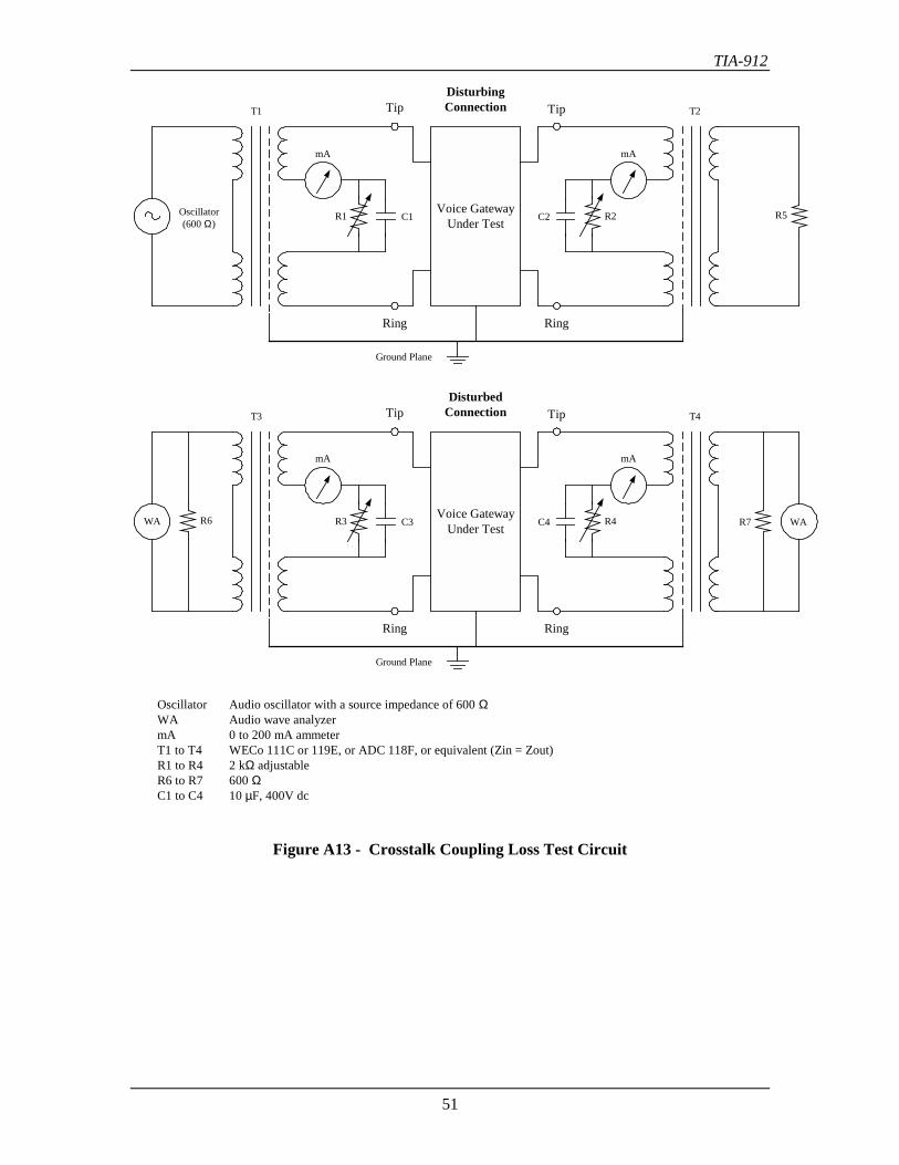
TIA-912
51
Voice GatewayUnder Test
Tip
Ring
Oscillator(600 Ω)
T1
Ground Plane
Oscillator Audio oscillator with a source impedance of 600 ΩWA Audio wave analyzermA 0 to 200 mA ammeterT1 to T4 WECo 111C or 119E, or ADC 118F, or equivalent (Zin = Zout)R1 to R4 2 kΩ adjustableR6 to R7 600 ΩC1 to C4 10 µF, 400V dc
C1R1
Tip
Ring
T2
C2 R2
Voice GatewayUnder Test
Tip
Ring
T3
Ground Plane
C3
mA
R3
Tip
Ring
T4
C4 R4 WAWA
DisturbingConnection
DisturbedConnection
R5
R6 R7
mA
mAmA
Figure A13 - Crosstalk Coupling Loss Test Circuit
TIA-912
52
Annex B (informative) - Telephony Loss Level Planning OverviewThis annex is informative only and is not part of this standard
B.1. IntroductionTelephony loss planning is concerned with the end-to-end loss between the sender and receiverover a telephony network.
It is called a loss plan, as the primary purpose is to approximate the free air loss between a talkerand listener in a normal conversation. A secondary purpose is to control echo due to impedancemismatches in connections with long delays.
The loss plan is also related to the optimization of signal levels in equipment involved in the end-to-end connection, and to the provisions of IS-968 regarding the prevention of network harm.
B.2. Send and Receive LevelsThe objective of a telephone connection is to simulate a 1 meter free air path between twotalkers. This simulation involves several objective and subjective factors that are not present inthe 1 meter air path. These include monaural listening, narrowband frequency response, thepreferred listening level and others. For any telephone connection, the optimum OLR to achievethe preferred listening level is 10 dB. In a digital connection, the network loss is zero; therefore,the required loudness ratings are adjusted in the send and receive sections of the digital telephoneset.
The send and receive levels of a telephone relate the conversion of acoustic pressure to electricalpower and vice versa. The acoustic pressure units are in dBPa (Pascals), and the electrical powerunits are in dB mW.
Pressure is measured in Newtons per square meter (Pascals), and the relationship betweendBSPL and dBPa is shown below.
dBSPL dBPa94 0 One Pascal
89.3 -4.7 Average speech level
0 -94 Lower limit of human hearing
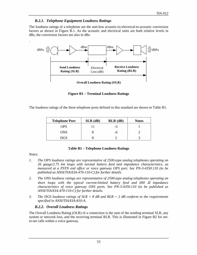
TIA-912
53
B.2.1. Telephone Equipment Loudness RatingsThe loudness ratings of a telephone are the unit-less acoustic-to-electrical-to-acoustic conversionfactors as shown in Figure B.1. As the acoustic and electrical units are both relative levels indBs, the conversion factors are also in dBs
.
dBPadBPa
Send LoudnessRating (SLR)
Receive LoudnessRating (RLR)
Overall Loudness Rating (OLR)
ElectricalLoss (dB)
dBm dBm
Figure B1 – Terminal Loudness Ratings
The loudness ratings of the three telephone ports defined in this standard are shown in Table B1.
Telephone Port SLR (dB) RLR (dB) NotesOPS 11 -3 1ONS 8 -6 2DGS 8 2 3
Table B1 – Telephone Loudness RatingsNotes:
1. The OPS loudness ratings are representative of 2500-type analog telephones operating on26 gauge/2.75 km loops with normal battery feed and impedance characteristics, asmeasured at a PSTN end office or voice gateway OPS port. See PN-3-4350.110 (to bepublished as ANSI/TIA/EIA-470-110-C) for further details.
2. The ONS loudness ratings are representative of 2500-type analog telephones operating onshort loops with the typical current-limited battery feed and 600 Ω impedancecharacteristics of voice gateway ONS ports. See PN-3-4350.110 (to be published asANSI/TIA/EIA-470-110-C) for further details.
3. The DGS loudness ratings of SLR = 8 dB and RLR = 2 dB conform to the requirementsspecified in ANSI/TIA/EIA-810-A.
B.2.2. Overall Loudness RatingsThe Overall Loudness Rating (OLR) of a connection is the sum of the sending terminal SLR, anysystem or network loss, and the receiving terminal RLR. This is illustrated in Figure B2 for set-to-set calls within a voice gateway.
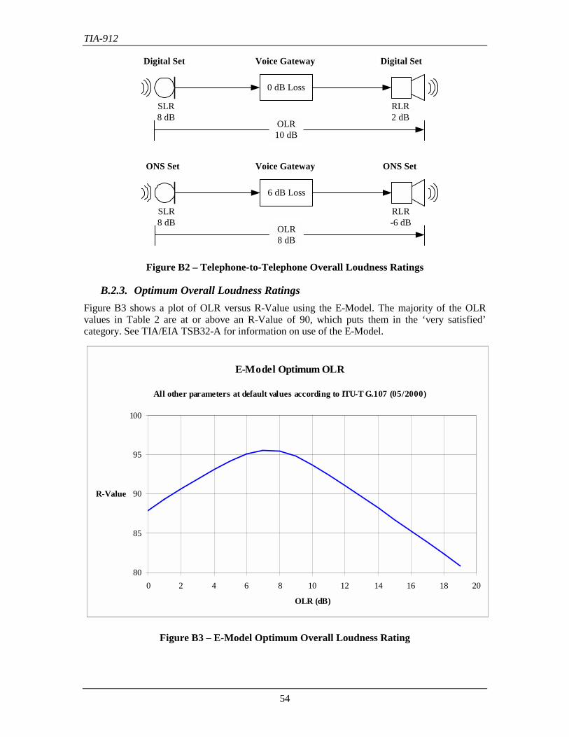
TIA-912
54
6 dB Loss
SLR8 dB
RLR-6 dB
OLR8 dB
ONS Set ONS Set
Digital Set Digital SetVoice Gateway
0 dB Loss
SLR8 dB
RLR2 dB
OLR10 dB
Voice Gateway
Figure B2 – Telephone-to-Telephone Overall Loudness Ratings
B.2.3. Optimum Overall Loudness RatingsFigure B3 shows a plot of OLR versus R-Value using the E-Model. The majority of the OLRvalues in Table 2 are at or above an R-Value of 90, which puts them in the ‘very satisfied’category. See TIA/EIA TSB32-A for information on use of the E-Model.
E-Model Optimum OLR
All other parameters at default values according to ITU-T G.107 (05/2000)
80
85
90
95
100
0 2 4 6 8 10 12 14 16 18 20
OLR (dB)
R-Value
Figure B3 – E-Model Optimum Overall Loudness Rating
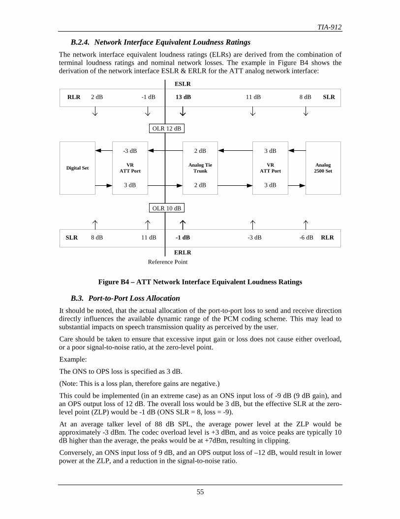
TIA-912
55
B.2.4. Network Interface Equivalent Loudness RatingsThe network interface equivalent loudness ratings (ELRs) are derived from the combination ofterminal loudness ratings and nominal network losses. The example in Figure B4 shows thederivation of the network interface ESLR & ERLR for the ATT analog network interface:
Digital Set
3 dB
VRATT Port
3 dB
Analog2500 Set
OLR 12 dB
OLR 10 dB
RLR 2 dB -1 dB 11 dB SLR13 dB 8 dB
SLR 8 dB 11 dB -3 dB RLR-1 dB -6 dB
Reference Point
2 dB
Analog TieTrunk
2 dB
-3 dB
VRATT Port
3 dB
ESLR
ERLR
Figure B4 – ATT Network Interface Equivalent Loudness Ratings
B.3. Port-to-Port Loss AllocationIt should be noted, that the actual allocation of the port-to-port loss to send and receive directiondirectly influences the available dynamic range of the PCM coding scheme. This may lead tosubstantial impacts on speech transmission quality as perceived by the user.
Care should be taken to ensure that excessive input gain or loss does not cause either overload,or a poor signal-to-noise ratio, at the zero-level point.
Example:
The ONS to OPS loss is specified as 3 dB.
(Note: This is a loss plan, therefore gains are negative.)
This could be implemented (in an extreme case) as an ONS input loss of -9 dB (9 dB gain), andan OPS output loss of 12 dB. The overall loss would be 3 dB, but the effective SLR at the zero-level point (ZLP) would be -1 dB (ONS SLR = 8, loss = -9).
At an average talker level of 88 dB SPL, the average power level at the ZLP would beapproximately -3 dBm. The codec overload level is +3 dBm, and as voice peaks are typically 10dB higher than the average, the peaks would be at +7dBm, resulting in clipping.
Conversely, an ONS input loss of 9 dB, and an OPS output loss of –12 dB, would result in lowerpower at the ZLP, and a reduction in the signal-to-noise ratio.
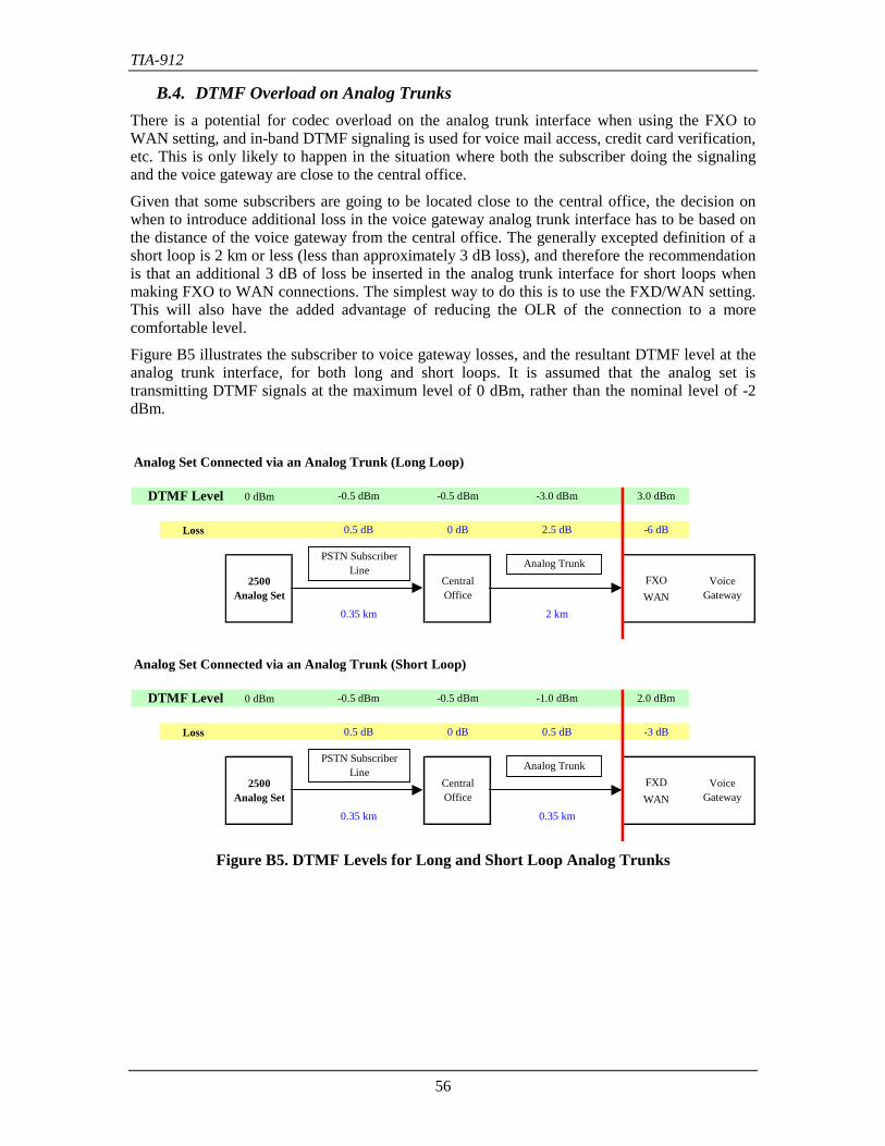
TIA-912
56
B.4. DTMF Overload on Analog TrunksThere is a potential for codec overload on the analog trunk interface when using the FXO toWAN setting, and in-band DTMF signaling is used for voice mail access, credit card verification,etc. This is only likely to happen in the situation where both the subscriber doing the signalingand the voice gateway are close to the central office.
Given that some subscribers are going to be located close to the central office, the decision onwhen to introduce additional loss in the voice gateway analog trunk interface has to be based onthe distance of the voice gateway from the central office. The generally excepted definition of ashort loop is 2 km or less (less than approximately 3 dB loss), and therefore the recommendationis that an additional 3 dB of loss be inserted in the analog trunk interface for short loops whenmaking FXO to WAN connections. The simplest way to do this is to use the FXD/WAN setting.This will also have the added advantage of reducing the OLR of the connection to a morecomfortable level.
Figure B5 illustrates the subscriber to voice gateway losses, and the resultant DTMF level at theanalog trunk interface, for both long and short loops. It is assumed that the analog set istransmitting DTMF signals at the maximum level of 0 dBm, rather than the nominal level of -2dBm.
Analog Set Connected via an Analog Trunk (Long Loop)
DTMF Level 0 dBm -0.5 dBm -0.5 dBm -3.0 dBm 3.0 dBm
Loss 0.5 dB 0 dB 2.5 dB -6 dB
FXOWAN
0.35 km 2 km
Analog Set Connected via an Analog Trunk (Short Loop)
DTMF Level 0 dBm -0.5 dBm -0.5 dBm -1.0 dBm 2.0 dBm
Loss 0.5 dB 0 dB 0.5 dB -3 dB
FXDWAN
0.35 km 0.35 km
2500 Analog Set
Central Office
Voice Gateway
2500 Analog Set
Central Office
Voice Gateway
PSTN Subscriber Line Analog Trunk
PSTN Subscriber Line Analog Trunk
Figure B5. DTMF Levels for Long and Short Loop Analog Trunks
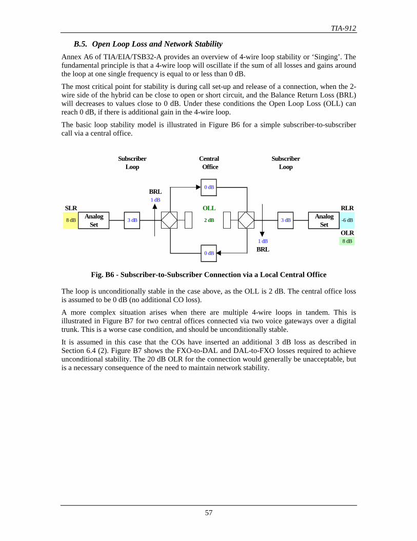
TIA-912
57
B.5. Open Loop Loss and Network StabilityAnnex A6 of TIA/EIA/TSB32-A provides an overview of 4-wire loop stability or ‘Singing’. Thefundamental principle is that a 4-wire loop will oscillate if the sum of all losses and gains aroundthe loop at one single frequency is equal to or less than 0 dB.
The most critical point for stability is during call set-up and release of a connection, when the 2-wire side of the hybrid can be close to open or short circuit, and the Balance Return Loss (BRL)will decreases to values close to 0 dB. Under these conditions the Open Loop Loss (OLL) canreach 0 dB, if there is additional gain in the 4-wire loop.
The basic loop stability model is illustrated in Figure B6 for a simple subscriber-to-subscribercall via a central office.
Subscriber Central SubscriberLoop Office Loop
BRL1 dB
SLR OLL RLRAnalog Analog
Set SetOLR
1 dB 8 dBBRL
8 dB -6 dB
0 dB
3 dB 2 dB 3 dB
0 dB
Fig. B6 - Subscriber-to-Subscriber Connection via a Local Central Office
The loop is unconditionally stable in the case above, as the OLL is 2 dB. The central office lossis assumed to be 0 dB (no additional CO loss).
A more complex situation arises when there are multiple 4-wire loops in tandem. This isillustrated in Figure B7 for two central offices connected via two voice gateways over a digitaltrunk. This is a worse case condition, and should be unconditionally stable.
It is assumed in this case that the COs have inserted an additional 3 dB loss as described inSection 6.4 (2). Figure B7 shows the FXO-to-DAL and DAL-to-FXO losses required to achieveunconditional stability. The 20 dB OLR for the connection would generally be unacceptable, butis a necessary consequence of the need to maintain network stability.
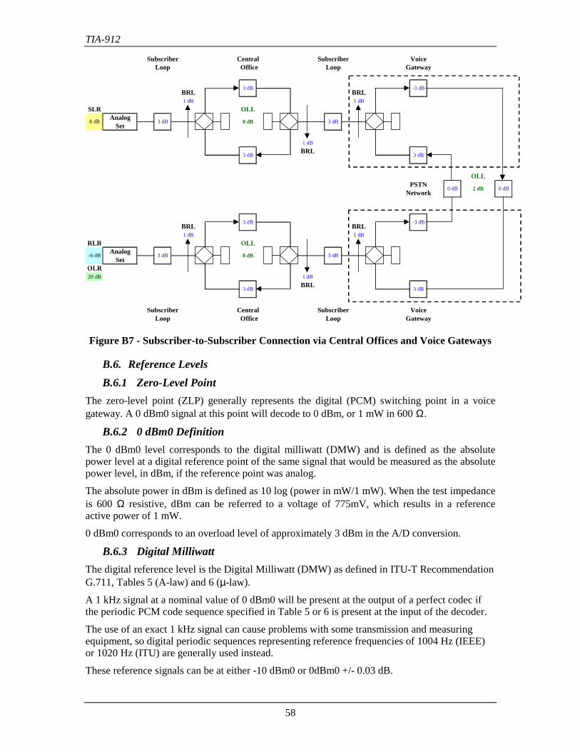
TIA-912
58
Subscriber Central Subscriber VoiceLoop Office Loop Gateway
BRL BRL1 dB 1 dB
SLR OLLAnalog
Set
1 dBBRL
OLLPSTN
Network
BRL BRL1 dB 1 dB
RLR OLLAnalog
SetOLR20 dB 1 dB
BRL
Subscriber Central Subscriber VoiceLoop Office Loop Gateway
3 dB
-3 dB
3 dB
8 dB
-6 dB
3 dB
3 dB 8 dB 3 dB
3 dB 3 dB
0 dB 0 dB2 dB
3 dB 8 dB 3 dB
3 dB -3 dB
Figure B7 - Subscriber-to-Subscriber Connection via Central Offices and Voice Gateways
B.6. Reference LevelsB.6.1 Zero-Level Point
The zero-level point (ZLP) generally represents the digital (PCM) switching point in a voicegateway. A 0 dBm0 signal at this point will decode to 0 dBm, or 1 mW in 600 Ω.
B.6.2 0 dBm0 DefinitionThe 0 dBm0 level corresponds to the digital milliwatt (DMW) and is defined as the absolutepower level at a digital reference point of the same signal that would be measured as the absolutepower level, in dBm, if the reference point was analog.
The absolute power in dBm is defined as 10 log (power in mW/1 mW). When the test impedanceis 600 Ω resistive, dBm can be referred to a voltage of 775mV, which results in a referenceactive power of 1 mW.
0 dBm0 corresponds to an overload level of approximately 3 dBm in the A/D conversion.
B.6.3 Digital MilliwattThe digital reference level is the Digital Milliwatt (DMW) as defined in ITU-T RecommendationG.711, Tables 5 (A-law) and 6 (µ-law).
A 1 kHz signal at a nominal value of 0 dBm0 will be present at the output of a perfect codec ifthe periodic PCM code sequence specified in Table 5 or 6 is present at the input of the decoder.
The use of an exact 1 kHz signal can cause problems with some transmission and measuringequipment, so digital periodic sequences representing reference frequencies of 1004 Hz (IEEE)or 1020 Hz (ITU) are generally used instead.
These reference signals can be at either -10 dBm0 or 0dBm0 +/- 0.03 dB.
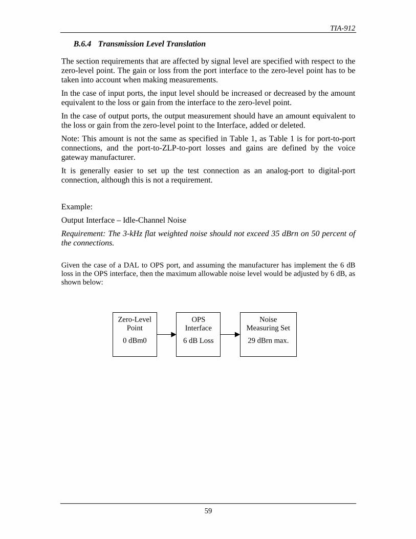
TIA-912
59
B.6.4 Transmission Level Translation
The section requirements that are affected by signal level are specified with respect to thezero-level point. The gain or loss from the port interface to the zero-level point has to betaken into account when making measurements.In the case of input ports, the input level should be increased or decreased by the amountequivalent to the loss or gain from the interface to the zero-level point.In the case of output ports, the output measurement should have an amount equivalent tothe loss or gain from the zero-level point to the Interface, added or deleted.Note: This amount is not the same as specified in Table 1, as Table 1 is for port-to-portconnections, and the port-to-ZLP-to-port losses and gains are defined by the voicegateway manufacturer.It is generally easier to set up the test connection as an analog-port to digital-portconnection, although this is not a requirement.
Example:Output Interface – Idle-Channel NoiseRequirement: The 3-kHz flat weighted noise should not exceed 35 dBrn on 50 percent ofthe connections.
Given the case of a DAL to OPS port, and assuming the manufacturer has implement the 6 dBloss in the OPS interface, then the maximum allowable noise level would be adjusted by 6 dB, asshown below:
NoiseMeasuring Set
29 dBrn max.
OPSInterface
6 dB Loss
Zero-LevelPoint
0 dBm0
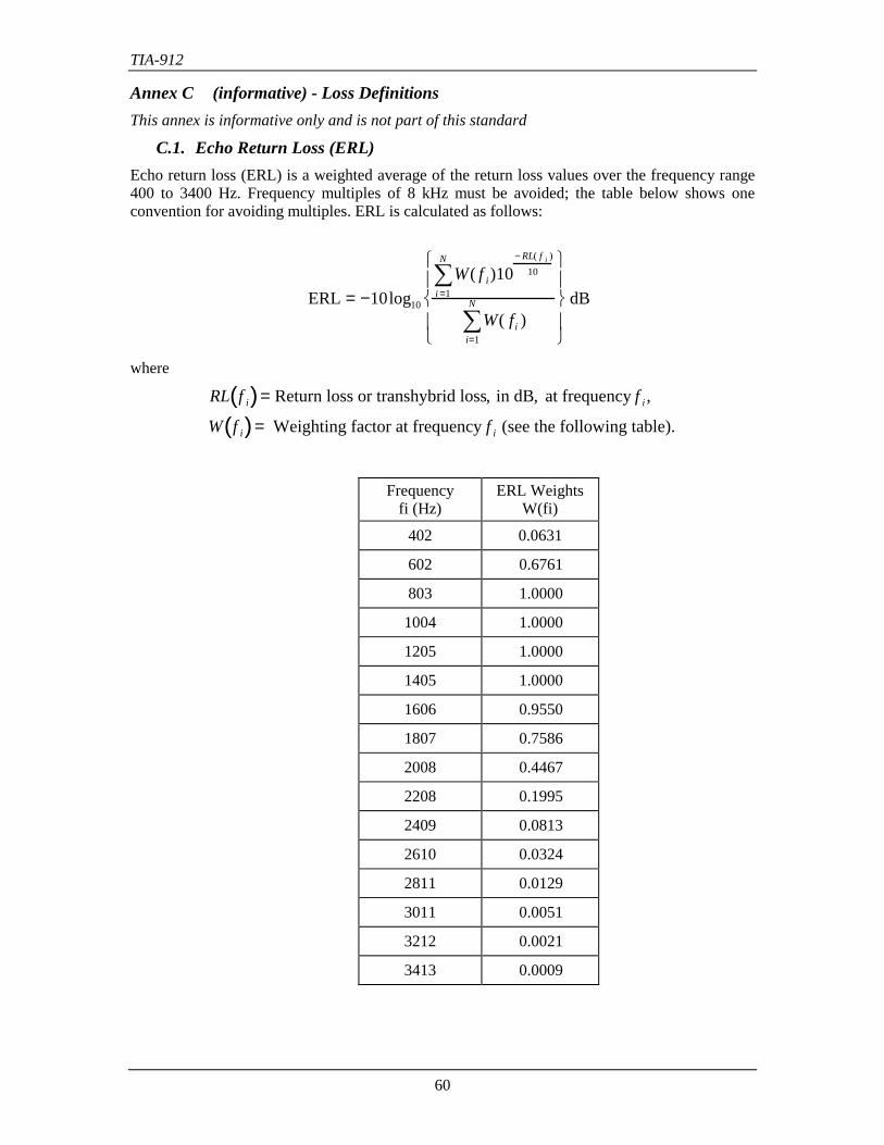
TIA-912
60
Annex C (informative) - Loss DefinitionsThis annex is informative only and is not part of this standard
C.1. Echo Return Loss (ERL)Echo return loss (ERL) is a weighted average of the return loss values over the frequency range400 to 3400 Hz. Frequency multiples of 8 kHz must be avoided; the table below shows oneconvention for avoiding multiples. ERL is calculated as follows:
ERL = −10log10
W( f i)10− RL( f i )
10
i =1
N
∑
W( fi )i=1
N
∑
dB
where
RL f i( )= Return loss or transhybrid loss, in dB, at frequency f i ,
W f i( )= Weighting factor at frequency f i (see the following table).
Frequencyfi (Hz)
ERL WeightsW(fi)
402 0.0631
602 0.6761
803 1.0000
1004 1.0000
1205 1.0000
1405 1.0000
1606 0.9550
1807 0.7586
2008 0.4467
2208 0.1995
2409 0.0813
2610 0.0324
2811 0.0129
3011 0.0051
3212 0.0021
3413 0.0009
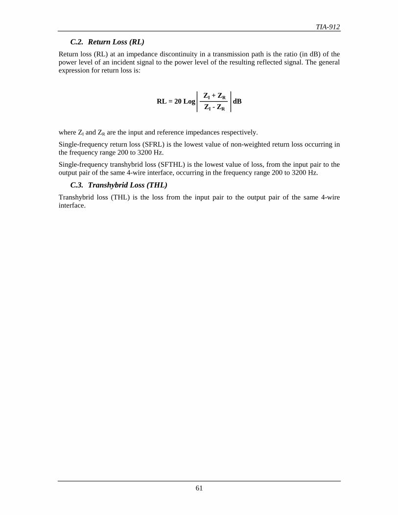
TIA-912
61
C.2. Return Loss (RL)Return loss (RL) at an impedance discontinuity in a transmission path is the ratio (in dB) of thepower level of an incident signal to the power level of the resulting reflected signal. The generalexpression for return loss is:
ZI + ZR
ZI - ZRRL = 20 Log dB
where ZI and ZR are the input and reference impedances respectively.
Single-frequency return loss (SFRL) is the lowest value of non-weighted return loss occurring inthe frequency range 200 to 3200 Hz.
Single-frequency transhybrid loss (SFTHL) is the lowest value of loss, from the input pair to theoutput pair of the same 4-wire interface, occurring in the frequency range 200 to 3200 Hz.
C.3. Transhybrid Loss (THL)Transhybrid loss (THL) is the loss from the input pair to the output pair of the same 4-wireinterface.
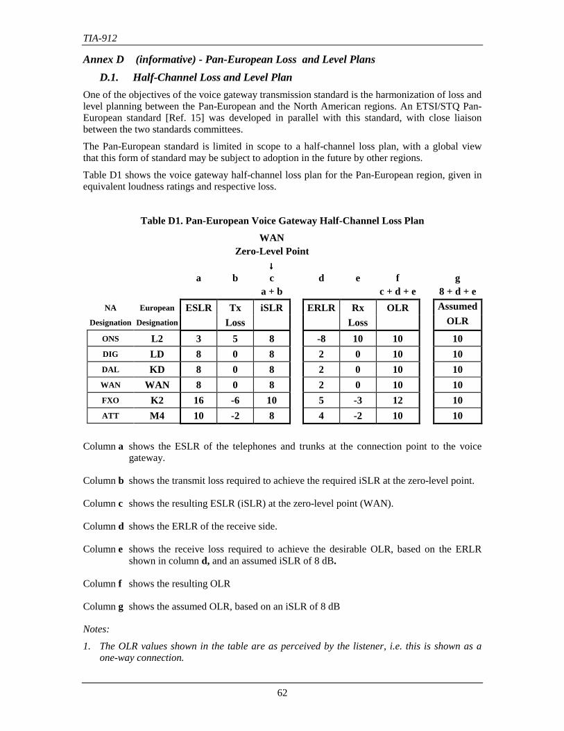
TIA-912
62
Annex D (informative) - Pan-European Loss and Level PlansD.1. Half-Channel Loss and Level Plan
One of the objectives of the voice gateway transmission standard is the harmonization of loss andlevel planning between the Pan-European and the North American regions. An ETSI/STQ Pan-European standard [Ref. 15] was developed in parallel with this standard, with close liaisonbetween the two standards committees.
The Pan-European standard is limited in scope to a half-channel loss plan, with a global viewthat this form of standard may be subject to adoption in the future by other regions.
Table D1 shows the voice gateway half-channel loss plan for the Pan-European region, given inequivalent loudness ratings and respective loss.
Table D1. Pan-European Voice Gateway Half-Channel Loss Plan
WANZero-Level Point
↓↓↓↓a b c d e f g
a + b c + d + e 8 + d + eNA European ESLR Tx iSLR ERLR Rx OLR Assumed
Designation Designation Loss Loss OLR
ONS L2 3 5 8 -8 10 10 10DIG LD 8 0 8 2 0 10 10DAL KD 8 0 8 2 0 10 10WAN WAN 8 0 8 2 0 10 10FXO K2 16 -6 10 5 -3 12 10ATT M4 10 -2 8 4 -2 10 10
Column a shows the ESLR of the telephones and trunks at the connection point to the voicegateway.
Column b shows the transmit loss required to achieve the required iSLR at the zero-level point.
Column c shows the resulting ESLR (iSLR) at the zero-level point (WAN).
Column d shows the ERLR of the receive side.
Column e shows the receive loss required to achieve the desirable OLR, based on the ERLRshown in column d, and an assumed iSLR of 8 dB.
Column f shows the resulting OLR
Column g shows the assumed OLR, based on an iSLR of 8 dB
Notes:
1. The OLR values shown in the table are as perceived by the listener, i.e. this is shown as aone-way connection.
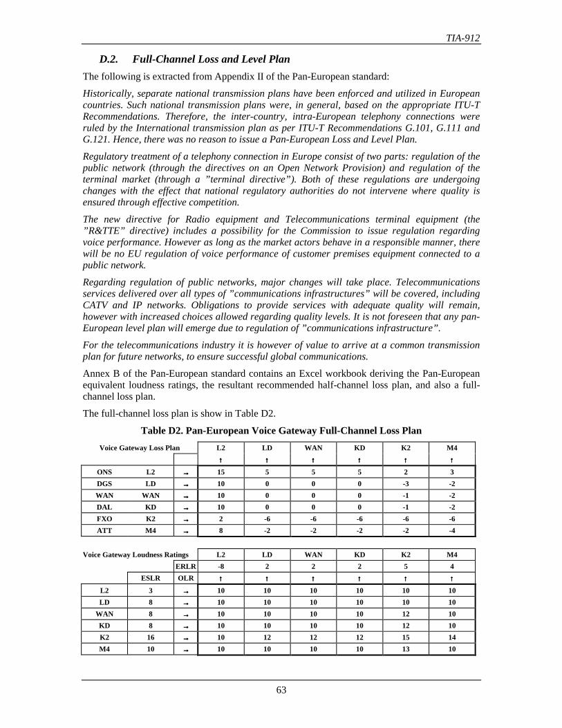
TIA-912
63
D.2. Full-Channel Loss and Level PlanThe following is extracted from Appendix II of the Pan-European standard:
Historically, separate national transmission plans have been enforced and utilized in Europeancountries. Such national transmission plans were, in general, based on the appropriate ITU-TRecommendations. Therefore, the inter-country, intra-European telephony connections wereruled by the International transmission plan as per ITU-T Recommendations G.101, G.111 andG.121. Hence, there was no reason to issue a Pan-European Loss and Level Plan.
Regulatory treatment of a telephony connection in Europe consist of two parts: regulation of thepublic network (through the directives on an Open Network Provision) and regulation of theterminal market (through a ”terminal directive”). Both of these regulations are undergoingchanges with the effect that national regulatory authorities do not intervene where quality isensured through effective competition.
The new directive for Radio equipment and Telecommunications terminal equipment (the”R&TTE” directive) includes a possibility for the Commission to issue regulation regardingvoice performance. However as long as the market actors behave in a responsible manner, therewill be no EU regulation of voice performance of customer premises equipment connected to apublic network.
Regarding regulation of public networks, major changes will take place. Telecommunicationsservices delivered over all types of ”communications infrastructures” will be covered, includingCATV and IP networks. Obligations to provide services with adequate quality will remain,however with increased choices allowed regarding quality levels. It is not foreseen that any pan-European level plan will emerge due to regulation of ”communications infrastructure”.
For the telecommunications industry it is however of value to arrive at a common transmissionplan for future networks, to ensure successful global communications.
Annex B of the Pan-European standard contains an Excel workbook deriving the Pan-Europeanequivalent loudness ratings, the resultant recommended half-channel loss plan, and also a full-channel loss plan.
The full-channel loss plan is show in Table D2.
Table D2. Pan-European Voice Gateway Full-Channel Loss PlanVoice Gateway Loss Plan L2 LD WAN KD K2 M4
↑↑↑↑ ↑↑↑↑ ↑↑↑↑ ↑↑↑↑ ↑↑↑↑ ↑↑↑↑
ONS L2 →→→→ 15 5 5 5 2 3DGS LD →→→→ 10 0 0 0 -3 -2WAN WAN →→→→ 10 0 0 0 -1 -2DAL KD →→→→ 10 0 0 0 -1 -2FXO K2 →→→→ 2 -6 -6 -6 -6 -6ATT M4 →→→→ 8 -2 -2 -2 -2 -4
Voice Gateway Loudness Ratings L2 LD WAN KD K2 M4ERLR -8 2 2 2 5 4
ESLR OLR ↑↑↑↑ ↑↑↑↑ ↑↑↑↑ ↑↑↑↑ ↑↑↑↑ ↑↑↑↑
L2 3 →→→→ 10 10 10 10 10 10LD 8 →→→→ 10 10 10 10 10 10
WAN 8 →→→→ 10 10 10 10 12 10KD 8 →→→→ 10 10 10 10 12 10K2 16 →→→→ 10 12 12 12 15 14M4 10 →→→→ 10 10 10 10 13 10
TIA-912
64
Annex E (informative) - IP Transmission Impairments
The effects of impairments introduced by IP networks are described in TIA/EIA/TSB116, VoiceQuality Recommendations for IP Telephony. The effects of impairments are evaluated using theE-model [Ref. 14], which includes the effects of both the terminal equipment (end points) andthe transmission network.
IP networks impact two of the impairment parameters; end-to-end delay and packet loss.Unfortunately both these have significant effects on speech quality.
A voice gateway is also likely to perform TDM/IP conversions, and will need to employ echocancellers if there are any 2-to-4 wire converters on the TDM side of the conversion.
E.1 Delay
End-to-end delay is a combination of the:
• The sending end point encoding and packetizing delay
• The network processing and propagation delay
• The receiving end point jitter buffer, depacketizing, and decoding delay
There is an interaction between the network delay and the receiving end point delay, in that theend point has to compensate for network delay variances via a jitter buffer, and increasedvariances lead to longer average delay in the end point.
Note: Other processes such as transcoding or encryption will also add delay.
E.2 Packet Loss
Packets can be lost either in the network, or can be discarded by the end point because they aretoo late (delayed beyond the range of the jitter buffer). In this case there is an interaction betweennetwork delay variances and packet loss in the end point.
E.3 Voice Gateways and Network Performance
The purpose of standards for voice transmission is to ensure that voice quality is achieved byadherence to the standards.
In a PBX standard the TDM transmission and switching is a dedicated resource within the PBXframework, and under normal conditions has little or no impact on voice quality.
In a Voice Gateway standard transmission and switching is via IP networks, which can introduceimpairments as noted above, and may also be shared by other entities beyond the control of thevoice gateway. Ensuring good voice quality will therefore require the use of managed networksand other techniques, which is beyond the scope of this standard.
TIA-912
65
E.4 Voice Quality of Service
There are a number of standards groups addressing the issue of voice quality of service (QoS).Users of this standard should ensure they are familiar with the work of these groups, as themethods and techniques for managing voice QoS are constantly evolving.
Some of the major groups involved in IP telephony voice QoS are listed below:
TIA Telecommunications Industry Associationwww.tiaonline.org
TR-41 User Premises Telecommunications Requirements
IETF Internet Engineering Task Forcewww.ietf.org
MPLS Multiprotocol Label Switching
DIFFSERV Differentiated Services
ITU-T International Telecommunication Union - Telecommunication StandardizationSector
www.itu.int/ITU-T
ITU-T SG 12 End-to-end transmission performance of networks and terminals
ETSI European Telecommunications Standards Institutewww.etsi.org
TIPHON Telecommunications and Internet Protocol Harmonization over Networks
STQ Speech Processing, Transmission and Quality Aspects