Embed Size (px)
Citation preview
PL201708 EN LIMITED PRODUCT WARRANTY SOLAR INVERTERS - V. 1.0
Solar Solutions GmbH | Schneckenhofstrasse 19 | 60596 Frankfurt am Main | Germany | www.aeg-industrialsolar.de
1-5
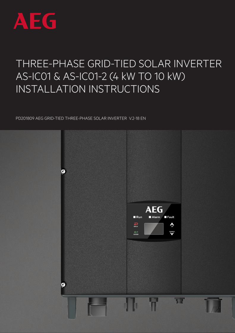
THREE-PHASE GRID-TIED SOLAR INVERTER AS-IC01 & AS-IC01-2 (4 kW TO 10 kW)INSTALLATION INSTRUCTIONS
PD201809 AEG GRID-TIED THREE-PHASE SOLAR INVERTER V.2-18 EN
1
PD201809 AEG GRID-TIED THREE-PHASE SOLAR INVERTER (4-10 kW) V.2-18 EN
1
AEG GRID-TIED THREE-PHASE SOLAR INVERTER INSTALLATION MANUAL
Thank you for choosing the reliability of AEG grid-tied solar inverters! This installation manual is intended for dealers and installers involved in the planning, installation and commissioning of photovoltaic systems deploying AEG solar inverters. These instructions are meant to provide you with valuable information to ensure that your PV installation runs smoothly and achieves optimal yields over its whole lifecycle. AEG grid-tied solar inverters are tested and approved by acknowledged independent certification authorities and can only be installed by qualified professional companies. Please observe the standards and regulations applying to photovoltaic systems in the relevant countries, as well as the rules of the employers’ liability insurance associations for accident protection. Failure to comply with these can result in major injuries and damage.
Product series: AEG grid-tied three-phase solar inverters AS-IC01-xxx and AS-IC01-xxx-2 (4 kW to 10 kW)
2
PD201809 AEG GRID-TIED THREE-PHASE SOLAR INVERTER (4-10 kW) V.2-18 EN
2
Table of Contents
Table of Contents ........................................................................................................................................................................................................................................... 2
1. Safety Precautions ....................................................................................................................................................................................................................................... 4
1.1 Icons ............................................................................................................................................................................................................................................................ 4
1.2 Safety Guidelines ..................................................................................................................................................................................................................... 4
1.2.1 Delivery and Installation .................................................................................................................................................................................................... 5
1.2.2 Grid-tied operation ................................................................................................................................................................................................................ 6
1.2.3 Maintenance and Inspection ........................................................................................................................................................................................ 7
1.2.4 Storage .............................................................................................................................................................................................................................................. 7
1.2.5 Product End of Life ............................................................................................................................................................................................................... 8
2. Product Overview ........................................................................................................................................................................................................................................ 8
2.1 Solar Grid-tied Power Generation Systems .............................................................................................................................................................. 8
2.1.1 Application...................................................................................................................................................................................................................................... 8
2.1.2 Supported grid connection structure .................................................................................................................................................................. 9
2.2 Product Appearance ................................................................................................................................................................................................................... 10
2.3 Labels ........................................................................................................................................................................................................................................................... 11
2.3.1 Packaging labels ..................................................................................................................................................................................................................... 11
2.3.2 Product label ............................................................................................................................................................................................................................. 12
2.3.3 Product models ...................................................................................................................................................................................................................... 13
2.4 Technical parameters ................................................................................................................................................................................................................. 13
2.5 Dimensions and weight ............................................................................................................................................................................................................. 15
3. Installation ......................................................................................................................................................................................................................................................... 15
3.1 Unpacking inspection ................................................................................................................................................................................................................... 16
3.2 Before installation .................................................................................................................................................................................................................... 17
3.2.1 Installation tools ..................................................................................................................................................................................................................... 17
3.2.2 Installation place.................................................................................................................................................................................................................... 17
3.2.3 Connection cables ............................................................................................................................................................................................................... 19
3.2.4 Micro breakers ........................................................................................................................................................................................................................ 19
3.3 Mechanical installation ............................................................................................................................................................................................................. 20
3.3.1 Installation of three-phase inverters ................................................................................................................................................................ 20
3.4 Electrical installation.................................................................................................................................................................................................................... 22
3
PD201809 AEG GRID-TIED THREE-PHASE SOLAR INVERTER (4-10 kW) V.2-18 EN
3
3.4.1 Connection of solar modules .................................................................................................................................................................................... 23
3.4.2 AC connection of three-phase inverters 4 kW to 10 kW .............................................................................................................. 24
4. Operation.......................................................................................................................................................................................................................................................... 25
4.1 Inspection before operation ................................................................................................................................................................................................. 25
4.2 Grid-tied operation ....................................................................................................................................................................................................................... 26
4.3 Stop .............................................................................................................................................................................................................................................................. 27
4.4 Maintenance .............................................................................................................................................................................................................................. 27
4.4.1 Regular maintenance ................................................................................................................................................................................................. 27
4.4.2 Maintenance guide ........................................................................................................................................................................................................... 28
5. Display and operation panel ......................................................................................................................................................................................................... 30
5.1 LED indicators ..................................................................................................................................................................................................................................... 31
5.2 Operation panel................................................................................................................................................................................................................................ 32
5.3 LCD screen............................................................................................................................................................................................................................................ 32
5.4 Functions operation ..................................................................................................................................................................................................................... 33
5.4.1 Monitoring parameters .................................................................................................................................................................................................. 33
5.4.2 History ........................................................................................................................................................................................................................................... 33
5.4.3 Statistics ....................................................................................................................................................................................................................................... 34
5.4.4 Parameter settings ............................................................................................................................................................................................................ 34
5.4.5 System Information ............................................................................................................................................................................................................41
5.4.6 Faults ...............................................................................................................................................................................................................................................41
5.4.7 Inverter control .......................................................................................................................................................................................................................41
5.4.8 Mode settings......................................................................................................................................................................................................................... 43
5.5 Choice of grid standard ............................................................................................................................................................................................................ 43
6. Monitoring communication ............................................................................................................................................................................................................ 44
6.1 AEG WiFi200 (AEG WiFi Stick) communication module ......................................................................................................................... 45
6.1.1 AEG WiFi Stick product overview ......................................................................................................................................................................... 45
6.1.2 Remote Monitoring and Local Monitoring; the AEG InverterControl App and Portal .................................... 46
6.2 Optional communication ........................................................................................................................................................................................................ 48
6.3 Pins on inverter ............................................................................................................................................................................................................................... 48
7. Troubleshooting ....................................................................................................................................................................................................................................... 48
8. Contact............................................................................................................................................................................................................................................................... 50
9. Annex: Warranty Card ........................................................................................................................................................................................................................... 51
4
PD201809 AEG GRID-TIED THREE-PHASE SOLAR INVERTER (4-10 kW) V.2-18 EN
4
1. Safety Precautions
This section describes relevant warning symbols recurring in the installation and operation manual of AEG three-phase solar inverters of the series AS-IC01 and AS-IC01-2. Icons highlight relevant information for the physical and property safety of the user. Compliance to the provided instructions is essential to prevent physical injury and product damage.
1.1 Icons Below is a list of the icons used in this manual:
Icon Meaning Instruction
Danger Serious physical injury or even death may occur in case of noncompliance with the requirement.
Warning Physical injury or product damage may occur in case of noncompliance with the requirement.
Prohibited Damage may occur in case of noncompliance with the requirement.
Hot surface Product surface may become hot. Do not touch.
Note Useful information for product maintenance and operation is provided
Table 1: Icon meaning
1.2 Safety Guidelines
5 minutes
Look for any visible damage to the package or the product itself. Double-check the order information and the product nameplate to ensure the products are of the ordered type. Should you find any problems, contact the shipping company and / or your supplier as soon as possible before attempting product installation. Only qualified electricians are allowed to install the inverter. Do not carry out any wiring and inspection nor change components when the inverter is connected to power supply. Hazardous voltages may still be present in the inverter even when the AC and DC main switches are turned off. Ensure that DC and AC side circuit breakers have been disconnected and wait at least 5 minutes after switching off the inverter to undertake any operation on the inverter. This ensures that the capacitors are electrically discharged.
5
PD201809 AEG GRID-TIED THREE-PHASE SOLAR INVERTER (4-10 kW) V.2-18 EN
5
The product can cause a DC current to be generated in the external protective earth conductor. In case of direct or indirect contact, a residual current-operated protective (RCD) or monitoring (RCM) device is strongly recommend to be used for protection. Only a RCD or RCM of Type B is allowed on the product’s supply side. Ensure that there is no electromagnetic interference from other electrical and electronic equipment at the installation site. Only use original parts and components. Do not unauthorizedly refit the inverter. All the electric installation needs to be compliant with the national or local laws and standards.
The temperature of individual parts or the enclosure of the inverter –especially the heat sink– may become hot during and due to normal operation. Avoid possible burns. Do not touch.
The inverter must be grounded before operation.
Do not unauthorizedly open the inverter cover. The electrical parts and components inside the inverter are electrostatic. Take measurements to avoid electrostatic discharge during relevant operations.
Technical personnel (Operators) who can carry out installation, wiring, commissioning, maintenance, troubleshooting and replacement of the AEG inverter series must meet the following requirements:
• The Operator has to be professionally trained • The Operator must read this manual completely and master the related safety precautions • The Operator needs to be fully familiar with the composition and operating principle of the
whole grid-tied photovoltaic power generation system and related standards of the coun-tries/regions where the installation / project is located.
• The Operator must wear personal protective equipment.
1.2.1 Delivery and Installation
AEG AS-IC01-2 series of grid-tied three-phase solar inverters are meant to be deployed only with crystalline silicon solar modules.
6
PD201809 AEG GRID-TIED THREE-PHASE SOLAR INVERTER (4-10 kW) V.2-18 EN
6
Keep the package and unit complete, dry and clean during storage and delivery. Due to product weight, lifting and installing the inverter requires two workers. Lift and install the inverter with appropriate tools to ensure safe and normal operation and avoid physical injury or death. Workers are also required to follow mechanical protective measures, such as wearing protective shoes and work clothes. Only qualified electricians are allowed to install the inverter. Do not put or install the inverter on or close to combustible materials. Keep the installation site away from children and public access. Remove metal accessories such as rings or bracelets before installation and electrical connection to avoid electric shock. Cover solar modules with light-tight materials. When exposed to light or sunlight, solar modules will generate potentially dangerous voltage and supply DC voltage to the inverter. The inverter input voltage must not exceed the maximum input voltage; otherwise inverter damage may occur. The positive and negative pole of solar modules should not be grounded, otherwise irrecoverable damage may occur.
Ensure the proper grounding of the inverter; improper connection or no grounding may cause the inverter to stop. Ensure reliable installation and electrical connection.
1.2.2 Grid-tied operation
Only qualified electricians are allowed to operate the inverter under the permission of local energy authorities. All electrical connections must meet the electrical standards of the countries/regions in which the installation / project is located. Ensure reliable installation and electrical connection before operation. Do not unauthorizedly open the inverter cover during operation. The electrical parts and components inside the inverter are electrostatic.
7
PD201809 AEG GRID-TIED THREE-PHASE SOLAR INVERTER (4-10 kW) V.2-18 EN
7
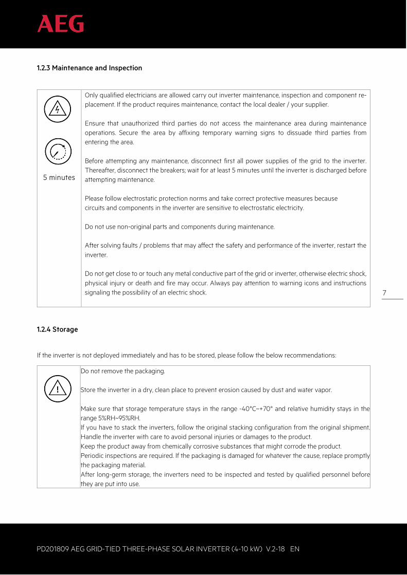
1.2.3 Maintenance and Inspection
5 minutes
Only qualified electricians are allowed carry out inverter maintenance, inspection and component re-placement. If the product requires maintenance, contact the local dealer / your supplier. Ensure that unauthorized third parties do not access the maintenance area during maintenance operations. Secure the area by affixing temporary warning signs to dissuade third parties from entering the area. Before attempting any maintenance, disconnect first all power supplies of the grid to the inverter. Thereafter, disconnect the breakers; wait for at least 5 minutes until the inverter is discharged before attempting maintenance. Please follow electrostatic protection norms and take correct protective measures because circuits and components in the inverter are sensitive to electrostatic electricity. Do not use non-original parts and components during maintenance. After solving faults / problems that may affect the safety and performance of the inverter, restart the inverter. Do not get close to or touch any metal conductive part of the grid or inverter, otherwise electric shock, physical injury or death and fire may occur. Always pay attention to warning icons and instructions signaling the possibility of an electric shock.
1.2.4 Storage
If the inverter is not deployed immediately and has to be stored, please follow the below recommendations:
Do not remove the packaging. Store the inverter in a dry, clean place to prevent erosion caused by dust and water vapor. Make sure that storage temperature stays in the range -40°C~+70° and relative humidity stays in the range 5%RH~95%RH. If you have to stack the inverters, follow the original stacking configuration from the original shipment. Handle the inverter with care to avoid personal injuries or damages to the product. Keep the product away from chemically corrosive substances that might corrode the product. Periodic inspections are required. If the packaging is damaged for whatever the cause, replace promptly the packaging material. After long-germ storage, the inverters need to be inspected and tested by qualified personnel before they are put into use.
8
PD201809 AEG GRID-TIED THREE-PHASE SOLAR INVERTER (4-10 kW) V.2-18 EN
8
1.2.5 Product End of Life
Please abide with local regulations for the inverter disposal. Do not dispose the inverter with household waste. The inverter and its components should be dealt with as industrial waste. The user has the responsibility and obligation to send the inverter to the locally appointed organization for recycling and disposal.
2. Product Overview
The following section describes product appearance, packaging, accessories, technical parameters and other relevant information concerning the AEG grid-tied three-phase solar inverters of the AS-IC01 and AS-IC01-2 series.
2.1 Solar Grid-tied Power Generation Systems
2.1.1 Application
Photovoltaic (solar) grid-tied power generation systems consist of solar modules, grid-tied inverters, metering devices, and public grid.
Figure 1: Scheme of solar grid-tied power generation system
The Grid-tied solar inverter is the core of photovoltaic power generation system. Solar energy is converted into DC electric energy through solar modules and is then transformed by grid-tied solar inverters into sinusoidal AC energy which has the same frequency and phase as the public grid; this electricity can then be fed to the grid.
Solar modules AEG solar inverter Net meter Electric grid
9
PD201809 AEG GRID-TIED THREE-PHASE SOLAR INVERTER (4-10 kW) V.2-18 EN
9
AEG AS-IC01 and AS-IC01-2 series of three-phase grid-tied solar inverters are only deployed in solar grid-tied power generation system. The DC input is only provided by crystalline silicon solar modules whose negative and positive poles are not grounded. Do not connect any AC loads between the inverter and breakers:
The solar modules need to be compliant with IEC 61730 Class A rating. AEG AS-IC01-2 series of grid-tied three-phase solar inverters are meant to be deployed only with crystalline silicon solar modules.
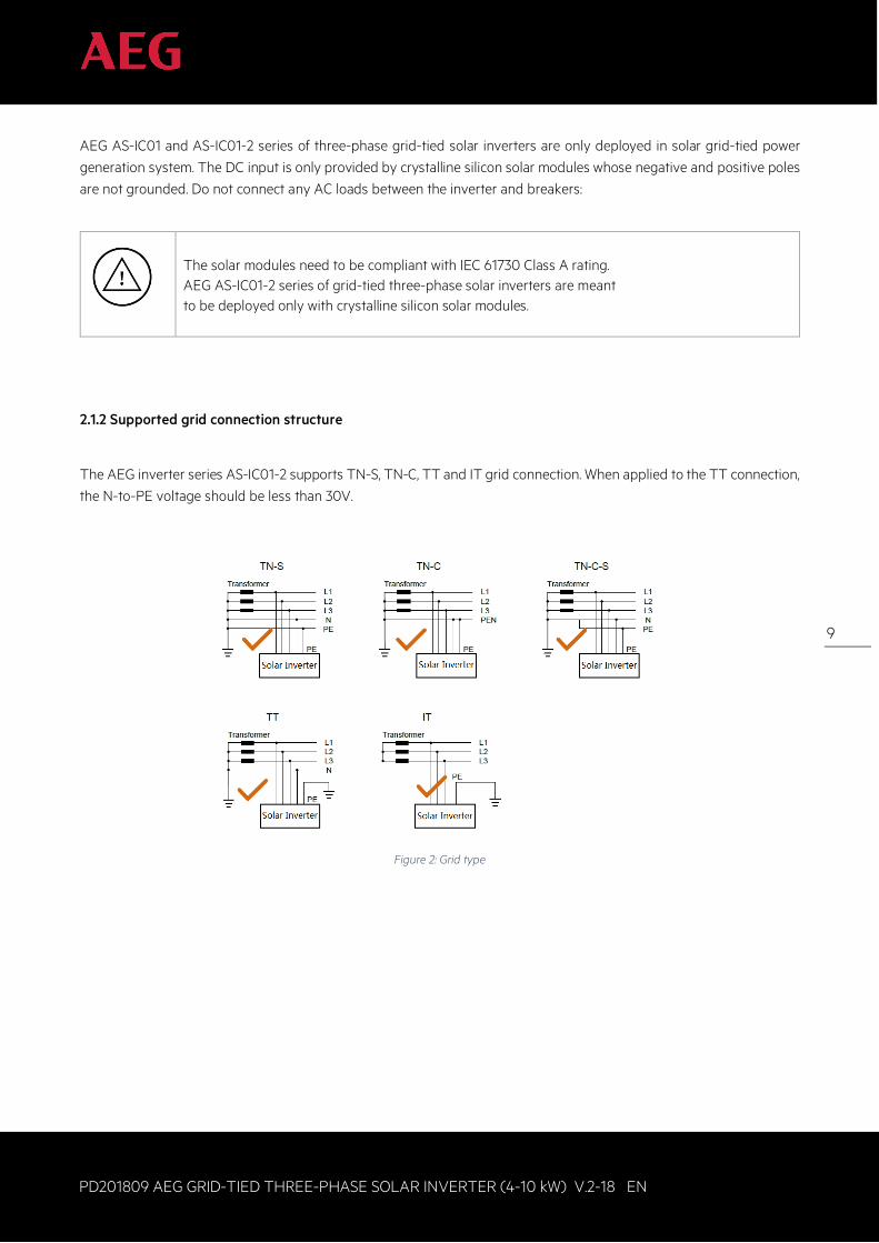
2.1.2 Supported grid connection structure
The AEG inverter series AS-IC01-2 supports TN-S, TN-C, TT and IT grid connection. When applied to the TT connection, the N-to-PE voltage should be less than 30V.
Figure 2: Grid type
10
PD201809 AEG GRID-TIED THREE-PHASE SOLAR INVERTER (4-10 kW) V.2-18 EN
10
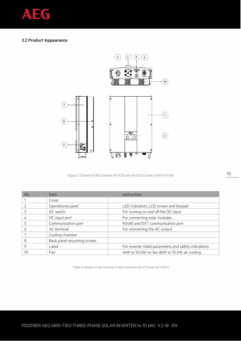
2.2 Product Appearance
Figure 3: Scheme of AEG inverter AS-IC01 and AS-IC01-2 series 4 kW to 10 kW
No. Item Instruction 1 Cover 2 Operational panel LED indicators, LCD screen and keypad 3 DC switch For turning on and off the DC input 4 DC input port For connecting solar modules 5 Communication port RS485 and EXT communication port 6 AC terminal For connecting the AC output 7 Cooling chamber 8 Back panel mounting screws 9 Label For inverter rated parameters and safety indications 10 Fan 4kW to 10 kW: no fan; 8kW to 10 kW: air cooling
Table 2: Details of the Scheme of AEG inverters AS-IC01 and AS-IC01-2
11
PD201809 AEG GRID-TIED THREE-PHASE SOLAR INVERTER (4-10 kW) V.2-18 EN
11
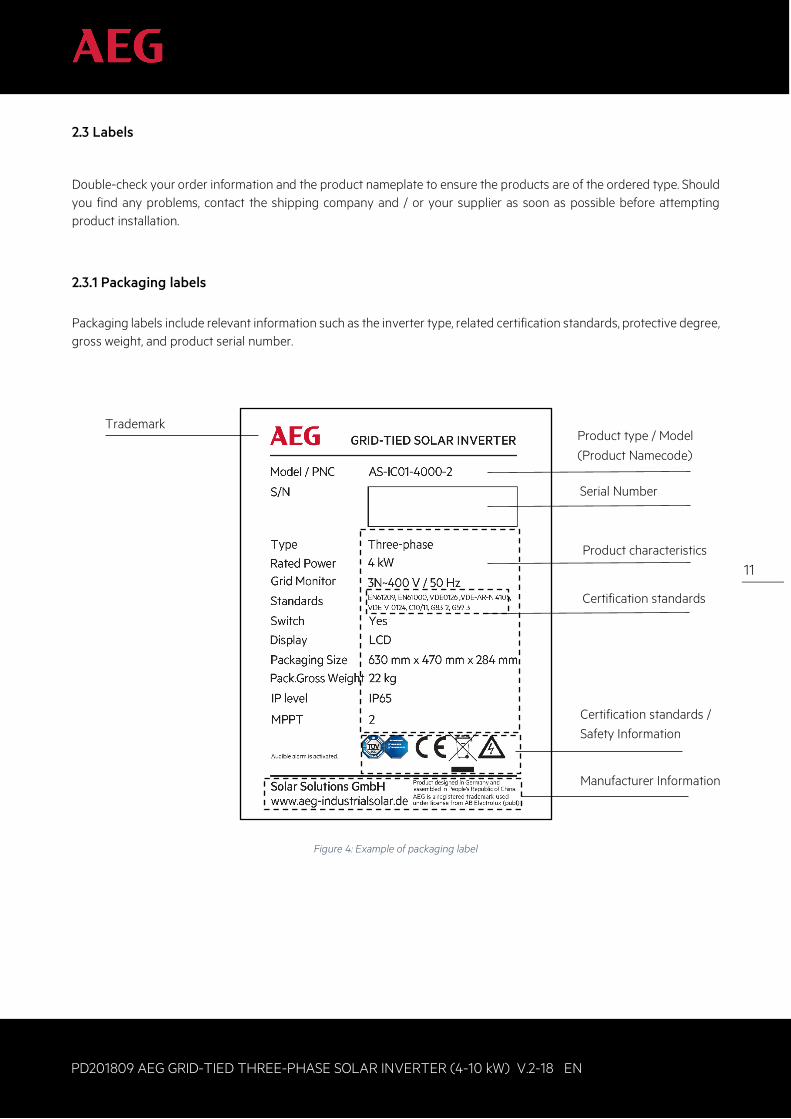
2.3 Labels
Double-check your order information and the product nameplate to ensure the products are of the ordered type. Should you find any problems, contact the shipping company and / or your supplier as soon as possible before attempting product installation.
2.3.1 Packaging labels Packaging labels include relevant information such as the inverter type, related certification standards, protective degree, gross weight, and product serial number.
Figure 4: Example of packaging label
Trademark Product type / Model
(Product Namecode)
Serial Number
Product characteristics
Certification standards
Certification standards / Safety Information
Manufacturer Information
12
PD201809 AEG GRID-TIED THREE-PHASE SOLAR INVERTER (4-10 kW) V.2-18 EN
12
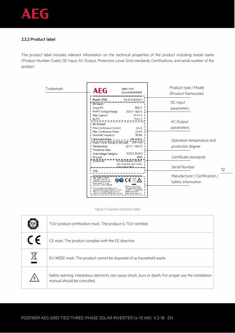
2.3.2 Product label
The product label includes relevant information on the technical properties of the product including model name (Product Number Code), DC Input, AC Output, Protection Level, Grid standards, Certifications, and serial number of the product.
Figure 5: Example of product label
TÜV product certification mark. The product is TÜV-certified
CE mark. The product complies with the CE directive.
EU WEEE mark. The product cannot be disposed of as household waste.
Safety warning: Hazardous electricity can cause shock, burs or death. For proper use the installation manual should be consulted.
Product type / Model
(Product Namecode)
DC Input
parameters
AC Output
parameters
Operation temperature and
protection degree
Serial Number
Manufacturer / Certification /
Safety Information
Certificate standards
Trademark
13
PD201809 AEG GRID-TIED THREE-PHASE SOLAR INVERTER (4-10 kW) V.2-18 EN
13
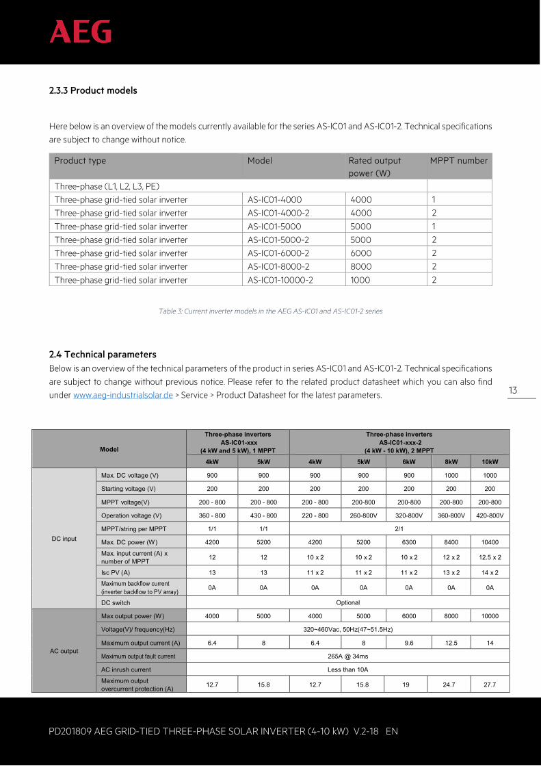
2.3.3 Product models
Here below is an overview of the models currently available for the series AS-IC01 and AS-IC01-2. Technical specifications are subject to change without notice.
Product type Model Rated output power (W)
MPPT number
Three-phase (L1, L2, L3, PE)
Three-phase grid-tied solar inverter AS-IC01-4000 4000 1
Three-phase grid-tied solar inverter AS-IC01-4000-2 4000 2
Three-phase grid-tied solar inverter AS-IC01-5000 5000 1
Three-phase grid-tied solar inverter AS-IC01-5000-2 5000 2
Three-phase grid-tied solar inverter AS-IC01-6000-2 6000 2
Three-phase grid-tied solar inverter AS-IC01-8000-2 8000 2
Three-phase grid-tied solar inverter AS-IC01-10000-2 1000 2
Table 3: Current inverter models in the AEG AS-IC01 and AS-IC01-2 series
2.4 Technical parameters Below is an overview of the technical parameters of the product in series AS-IC01 and AS-IC01-2. Technical specifications are subject to change without previous notice. Please refer to the related product datasheet which you can also find under www.aeg-industrialsolar.de > Service > Product Datasheet for the latest parameters.
Model
Three-phase inverters AS-IC01-xxx
(4 kW and 5 kW), 1 MPPT
Three-phase inverters AS-IC01-xxx-2
(4 kW - 10 kW), 2 MPPT 4kW 5kW 4kW 5kW 6kW 8kW 10kW
DC input
Max. DC voltage (V) 900 900 900 900 900 1000 1000
Starting voltage (V) 200 200 200 200 200 200 200
MPPT voltage(V) 200 - 800 200 - 800 200 - 800 200-800 200-800 200-800 200-800
Operation voltage (V) 360 - 800 430 - 800 220 - 800 260-800V 320-800V 360-800V 420-800V
MPPT/string per MPPT 1/1 1/1 2/1
Max. DC power (W) 4200 5200 4200 5200 6300 8400 10400
Max. input current (A) x number of MPPT 12 12 10 x 2 10 x 2 10 x 2 12 x 2 12.5 x 2
Isc PV (A) 13 13 11 x 2 11 x 2 11 x 2 13 x 2 14 x 2
Maximum backflow current (inverter backflow to PV array) 0A 0A 0A 0A 0A 0A 0A
DC switch Optional
AC output
Max output power (W) 4000 5000 4000 5000 6000 8000 10000
Voltage(V)/ frequency(Hz) 320~460Vac, 50Hz(47~51.5Hz)
Maximum output current (A) 6.4 8 6.4 8 9.6 12.5 14
Maximum output fault current 265A @ 34ms
AC inrush current Less than 10A
Maximum output overcurrent protection (A) 12.7 15.8 12.7 15.8 19 24.7 27.7
14
PD201809 AEG GRID-TIED THREE-PHASE SOLAR INVERTER (4-10 kW) V.2-18 EN
14
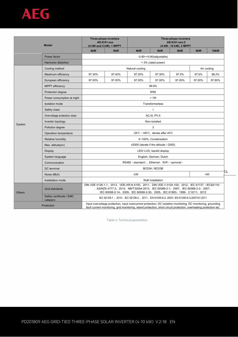
Model
Three-phase inverters AS-IC01-xxx
(4 kW and 5 kW), 1 MPPT
Three-phase inverters AS-IC01-xxx-2
(4 kW - 10 kW), 2 MPPT 4kW 5kW 4kW 5kW 6kW 8kW 10kW
Power factor -0.80~+0.80(adjustable)
Harmonic distortion < 3% (rated power)
System
Cooling method Natural cooling Air cooling
Maximum efficiency 97.30% 97.40% 97.20% 97.30% 97.5% 97.6% 98.2%
European efficiency 97.00% 97.00% 97.00% 97.00% 97.00% 97.00% 97.60%
MPPT efficiency 99.9%
Protection degree IP65
Power consumption at night < 1W
Isolation mode Transformerless
Safety class I
Overvoltage protection class AC:III, PV:II
Inverter topology Non-isolated
Pollution degree 3
Operation temperature -25℃~+60℃, derate after 45℃
Relative humidity 4~100%, Condensation
Max. altitude(m) ≤2000 (derate if the altitude>2000)
Display LED/ LCD, backlit display
System language English, German, Dutch
Communication RS485(standard), Ethernet,WiFi(oprional)
DC terminal BC03A / BC03B
Noise dB(A) ≤30 <50
Installation mode Wall installation
Others Grid standards
DIN VDE 0126-1-1:2013,VDE-AR-N 4105:2011,DIN VDE V 0124-100:2012,IEC 61727(IEC62116),AS/NZS 4777.2:2015,NB/T32004-2013,IEC 60068-2-1:2007,IEC 60068-2-2:2007,
IEC 60068-2-14:2009,IEC 60068-2-30:2005,IEC 61683:1999,C10/11:2012 Safety certificate / EMC category
IEC 62109-1 :2010,IEC 62109-2 :2011,EN 61000-6-2: 2005 / EN 61000-6-3:2007/A1:2011
Protection Input overvoltage protection, input overcurrent protection, DC isolation monitoring, DC monitoring, grounding fault current monitoring, grid monitoring, island protection, short circuit protection, overheating protection etc.
Table 4: Technical parameters
15
PD201809 AEG GRID-TIED THREE-PHASE SOLAR INVERTER (4-10 kW) V.2-18 EN
15
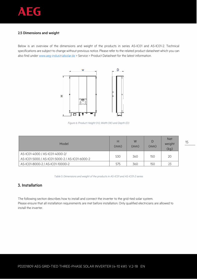
2.5 Dimensions and weight
Below is an overview of the dimensions and weight of the products in series AS-IC01 and AS-IC01-2. Technical specifications are subject to change without previous notice. Please refer to the related product datasheet which you can also find under www.aeg-industrialsolar.de > Service > Product Datasheet for the latest information.
Figure 6: Product Height (H), Width (W) and Depth (D)
Model H
(mm)
W
(mm)
D
(mm)
Net
weight
(kg)
AS-IC01-4000 / AS-IC01-4000-2/
AS-IC01-5000 / AS-IC01-5000-2 / AS-IC01-6000-2 530 360 150 20
AS-IC01-8000-2 / AS-IC01-10000-2 575 360 150 23
Table 5: Dimensions and weight of the products in AS-IC01 and AS-IC01-2 series
3. Installation
The following section describes how to install and connect the inverter to the grid-tied solar system. Please ensure that all installation requirements are met before installation. Only qualified electricians are allowed to install the inverter.
16
PD201809 AEG GRID-TIED THREE-PHASE SOLAR INVERTER (4-10 kW) V.2-18 EN
16
3.1 Unpacking inspection
When unpacking the product ensure that: 1. The inverter unit or the package show no damage; 2. The operation manual, port and installation accessories are found in the package; 3. No damage or loss has occurred to the items in the package; 4. The product type stated in your order corresponds to the one stated on the product label.
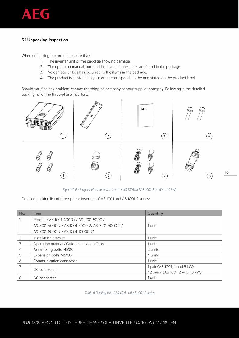
Should you find any problem, contact the shipping company or your supplier promptly. Following is the detailed packing list of the three-phase inverters:
Figure 7: Packing list of three-phase inverter AS-IC01 and AS-IC01-2 (4 kW to 10 kW)
Detailed packing list of three-phase inverters of AS-IC01 and AS-IC01-2 series:
No. Item Quantity
1 Product (AS-IC01-4000 / / AS-IC01-5000 /
AS-IC01-4000-2 / AS-IC01-5000-2/ AS-IC01-6000-2 /
AS-IC01-8000-2 / AS-IC01-10000-2)
1 unit
2 Installation bracket 1 unit 3 Operation manual / Quick Installation Guide 1 unit 4 Assembling bolts M5*20 2 units 5 Expansion bolts M6*50 4 units 6 Communication connector 1 unit 7
DC connector 1 pair (AS-IC01, 4 and 5 kW) / 2 pairs (AS-IC01-2, 4 to 10 kW)
8 AC connector 1 unit
Table 6 Packing list of AS-IC01 and AS-IC01-2 series
17
PD201809 AEG GRID-TIED THREE-PHASE SOLAR INVERTER (4-10 kW) V.2-18 EN
17
3.2 Before installation
3.2.1 Installation tools
Detailed list of the tools required for installation:
No. Installation tool Instruction 1 Marking pen Mark the installation hole 2 Electrodrill Drill in the bracket or wall 3 Hammer Hammer on the expansion bolts 4 Monkey wrench Fix the installation bracket 5 Allen driver Fasten the screws, remove and install AC wiring box
6 Slotted or cross-head screwdriver
For AC wiring
7 Megameter Measuring insulation performance and impedance 8 Multimeter Check the circuit and AC and DC voltage 9 Electric iron Weld communications cable 10 Wire crimper Crimp DC terminal
Table 7: Required installation tools
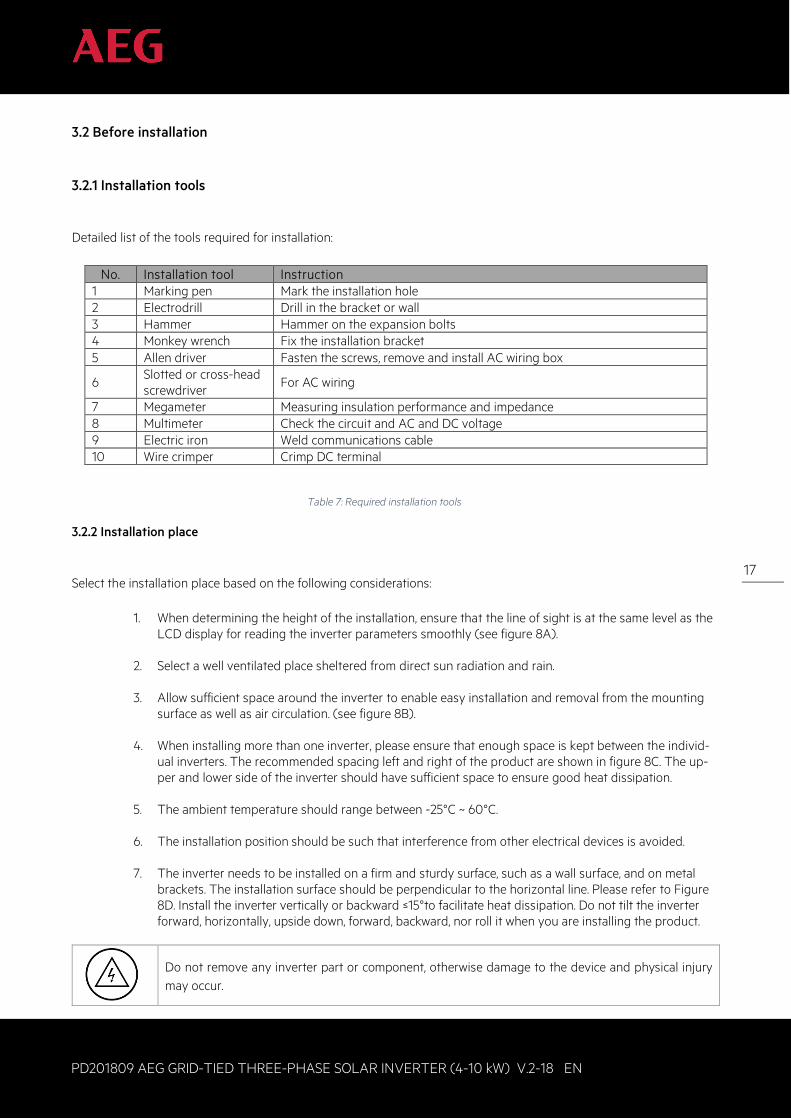
3.2.2 Installation place
Select the installation place based on the following considerations:
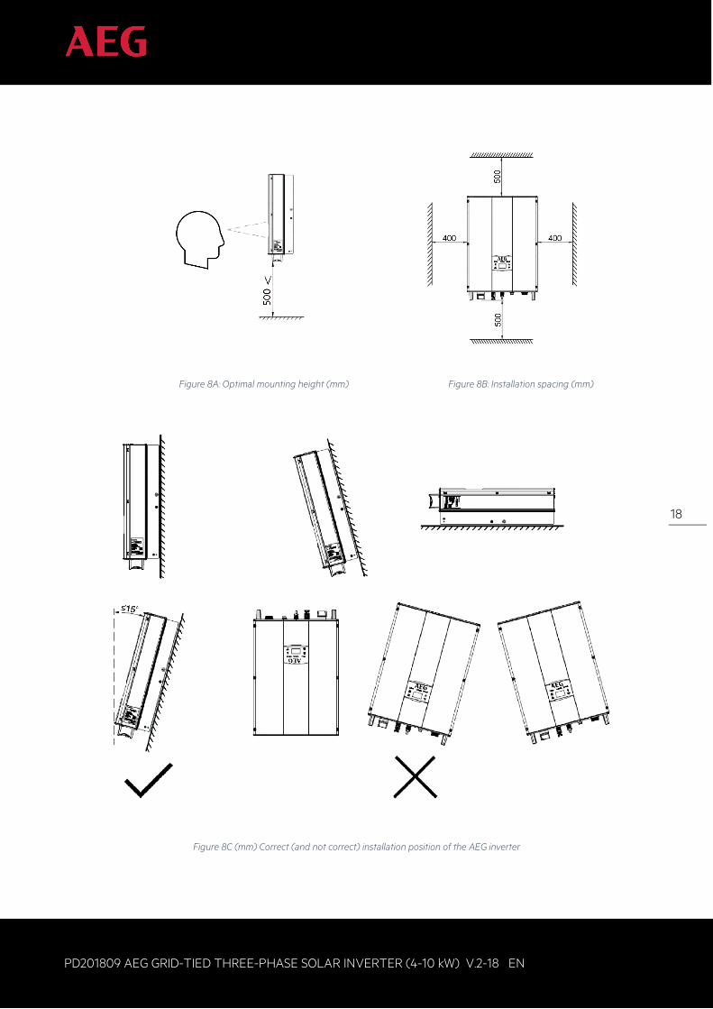
1. When determining the height of the installation, ensure that the line of sight is at the same level as the LCD display for reading the inverter parameters smoothly (see figure 8A).
2. Select a well ventilated place sheltered from direct sun radiation and rain.
3. Allow sufficient space around the inverter to enable easy installation and removal from the mounting surface as well as air circulation. (see figure 8B).
4. When installing more than one inverter, please ensure that enough space is kept between the individ-
ual inverters. The recommended spacing left and right of the product are shown in figure 8C. The up-per and lower side of the inverter should have sufficient space to ensure good heat dissipation.
5. The ambient temperature should range between -25°C ~ 60°C.
6. The installation position should be such that interference from other electrical devices is avoided.
7. The inverter needs to be installed on a firm and sturdy surface, such as a wall surface, and on metal
brackets. The installation surface should be perpendicular to the horizontal line. Please refer to Figure 8D. Install the inverter vertically or backward ≤15°to facilitate heat dissipation. Do not tilt the inverter forward, horizontally, upside down, forward, backward, nor roll it when you are installing the product.
Do not remove any inverter part or component, otherwise damage to the device and physical injury may occur.
18
PD201809 AEG GRID-TIED THREE-PHASE SOLAR INVERTER (4-10 kW) V.2-18 EN
18
Figure 8A: Optimal mounting height (mm) Figure 8B: Installation spacing (mm)
Figure 8C (mm) Correct (and not correct) installation position of the AEG inverter
19
PD201809 AEG GRID-TIED THREE-PHASE SOLAR INVERTER (4-10 kW) V.2-18 EN
19
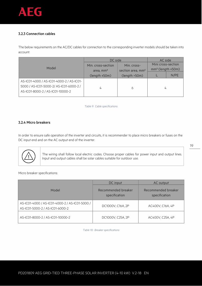
3.2.3 Connection cables
The below requirements on the AC/DC cables for connection to the corresponding inverter models should be taken into account:
Model
DC side AC side
Min. cross-section
area, mm²
(length ≤50m)
Min. cross-
section area, mm²
(length >50m)
Mini cross-section mm² (length ≤50m)
L N/PE
AS-IC01-4000 / AS-IC01-4000-2 / AS-IC01-
5000 / AS-IC01-5000-2/ AS-IC01-6000-2 /
AS-IC01-8000-2 / AS-IC01-10000-2
4 6 4
Table 9: Cable specifications
3.2.4 Micro breakers
In order to ensure safe operation of the inverter and circuits, it is recommender to place micro breakers or fuses on the DC input end and on the AC output end of the inverter.
The wiring shall follow local electric codes. Choose proper cables for power input and output lines. Input and output cables shall be solar cables suitable for outdoor use.
Micro breaker specifications:
Model
DC input AC output
Recommended breaker
specification
Recommended breaker
specification
AS-IC01-4000 / AS-IC01-4000-2 / AS-IC01-5000 /
AS-IC01-5000-2 / AS-IC01-6000-2 DC1000V, C16A, 2P AC400V, C16A, 4P
AS-IC01-8000-2 / AS-IC01-10000-2 DC1000V, C25A, 2P AC400V, C25A, 4P
Table 10: Breaker specifications
20
PD201809 AEG GRID-TIED THREE-PHASE SOLAR INVERTER (4-10 kW) V.2-18 EN
20
3.3 Mechanical installation
As the installation place can be chosen among different construction materials, the inverter can be installed by different
mounting methods. Taking the typical installation environment as the example, the manual describes how to install the
inverter on concrete wall.
The inverter should be mounted in a vertical position of 90°to the horizontal line as shown in figure 9 (see 3.2.2
“Installation place”).
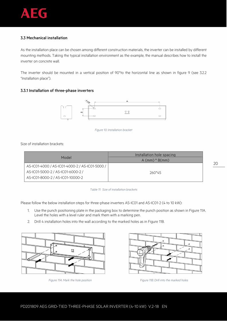
3.3.1 Installation of three-phase inverters
Figure 10: Installation bracket
Size of installation brackets:
Model Installation hole spacing
A (mm) * B(mm)
AS-IC01-4000 / AS-IC01-4000-2 / AS-IC01-5000 /
AS-IC01-5000-2 / AS-IC01-6000-2 /
AS-IC01-8000-2 / AS-IC01-10000-2
260*45
Table 11: Size of installation brackets
Please follow the below installation steps for three-phase inverters AS-IC01 and AS-IC01-2 (4 to 10 kW):
1. Use the punch positioning plate in the packaging box to determine the punch position as shown in Figure 11A. Level the holes with a level ruler and mark them with a marking pen.
2. Drill 4 installation holes into the wall according to the marked holes as in Figure 11B.
Figure 11A: Mark the hole position Figure 11B: Drill into the marked holes
21
PD201809 AEG GRID-TIED THREE-PHASE SOLAR INVERTER (4-10 kW) V.2-18 EN
21
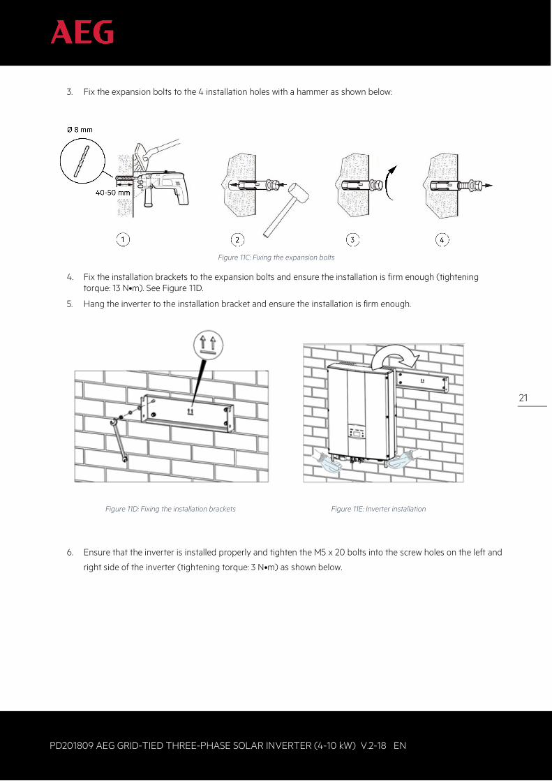
3. Fix the expansion bolts to the 4 installation holes with a hammer as shown below:
Figure 11C: Fixing the expansion bolts
4. Fix the installation brackets to the expansion bolts and ensure the installation is firm enough (tightening torque: 13 N•m). See Figure 11D.
5. Hang the inverter to the installation bracket and ensure the installation is firm enough.
Figure 11D: Fixing the installation brackets Figure 11E: Inverter installation
6. Ensure that the inverter is installed properly and tighten the M5 x 20 bolts into the screw holes on the left and
right side of the inverter (tightening torque: 3 N•m) as shown below.
22
PD201809 AEG GRID-TIED THREE-PHASE SOLAR INVERTER (4-10 kW) V.2-18 EN
22
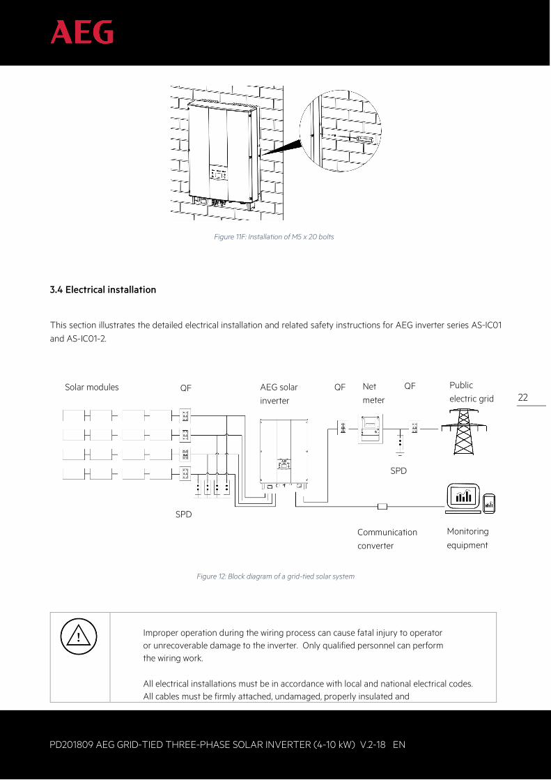
Figure 11F: Installation of M5 x 20 bolts
3.4 Electrical installation
This section illustrates the detailed electrical installation and related safety instructions for AEG inverter series AS-IC01 and AS-IC01-2.
Figure 12: Block diagram of a grid-tied solar system
Improper operation during the wiring process can cause fatal injury to operator or unrecoverable damage to the inverter. Only qualified personnel can perform the wiring work.
All electrical installations must be in accordance with local and national electrical codes. All cables must be firmly attached, undamaged, properly insulated and
Solar modules QF
SPD
AEG solar inverter
QF Net meter
SPD
QF Public electric grid
Monitoring
equipment Communication converter
23
PD201809 AEG GRID-TIED THREE-PHASE SOLAR INVERTER (4-10 kW) V.2-18 EN
23
adequately dimensioned. Do not switch off the AC and DC breakers before the inverter is electrically connected. Read and follow the instructions provided in this section while observing all safety warnings. Always note the rated voltage and current defined in this manual. Never exceed the limits.
3.4.1 Connection of solar modules
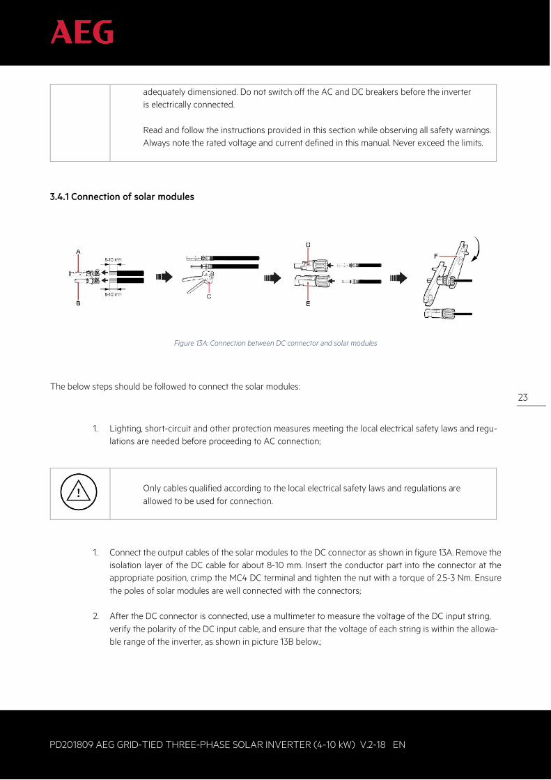
Figure 13A: Connection between DC connector and solar modules
The below steps should be followed to connect the solar modules:
1. Lighting, short-circuit and other protection measures meeting the local electrical safety laws and regu-lations are needed before proceeding to AC connection;
Only cables qualified according to the local electrical safety laws and regulations are allowed to be used for connection.
1. Connect the output cables of the solar modules to the DC connector as shown in figure 13A. Remove the isolation layer of the DC cable for about 8-10 mm. Insert the conductor part into the connector at the appropriate position, crimp the MC4 DC terminal and tighten the nut with a torque of 2.5-3 Nm. Ensure the poles of solar modules are well connected with the connectors;
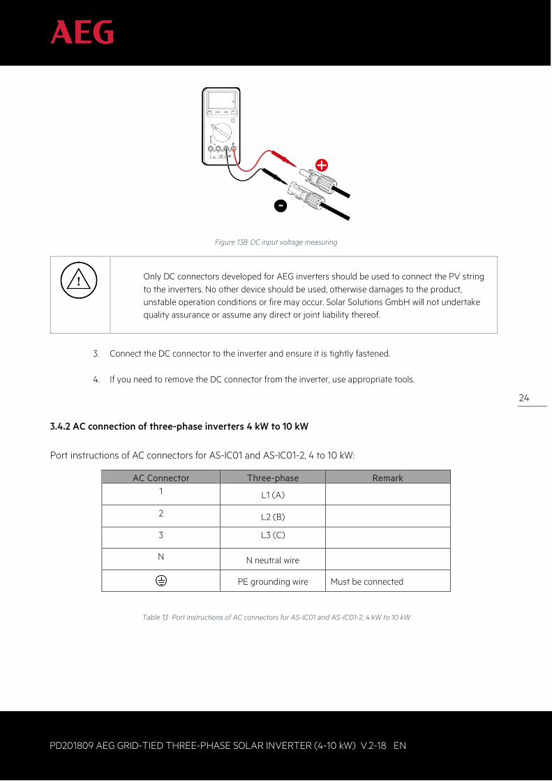
2. After the DC connector is connected, use a multimeter to measure the voltage of the DC input string,
verify the polarity of the DC input cable, and ensure that the voltage of each string is within the allowa-ble range of the inverter, as shown in picture 13B below.;
24
PD201809 AEG GRID-TIED THREE-PHASE SOLAR INVERTER (4-10 kW) V.2-18 EN
24
Figure 13B: DC input voltage measuring
Only DC connectors developed for AEG inverters should be used to connect the PV string to the inverters. No other device should be used, otherwise damages to the product, unstable operation conditions or fire may occur. Solar Solutions GmbH will not undertake quality assurance or assume any direct or joint liability thereof.
3. Connect the DC connector to the inverter and ensure it is tightly fastened.
4. If you need to remove the DC connector from the inverter, use appropriate tools.
3.4.2 AC connection of three-phase inverters 4 kW to 10 kW Port instructions of AC connectors for AS-IC01 and AS-IC01-2, 4 to 10 kW:
AC Connector Three-phase Remark 1 L1 (A)
2 L2 (B)
3 L3 (C)
N N neutral wire
PE grounding wire Must be connected
Table 13 Port instructions of AC connectors for AS-IC01 and AS-IC01-2, 4 kW to 10 kW
25
PD201809 AEG GRID-TIED THREE-PHASE SOLAR INVERTER (4-10 kW) V.2-18 EN
25
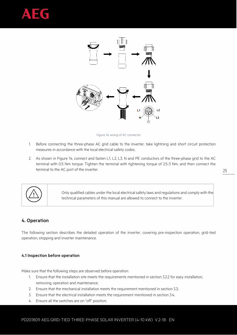
Figure 14: wiring of AC connector
1. Before connecting the three-phase AC grid cable to the inverter, take lightning and short circuit protection measures in accordance with the local electrical safety codes;
2. As shown in Figure 14, connect and fasten L1, L2, L3, N and PE conductors of the three-phase grid to the AC terminal with 0.5 Nm torque. Tighten the terminal with tightening torque of 2.5-3 Nm, and then connect the terminal to the AC port of the inverter.
Only qualified cables under the local electrical safety laws and regulations and comply with the technical parameters of this manual are allowed to connect to the inverter.
4. Operation The following section describes the detailed operation of the inverter, covering pre-inspection operation, grid-tied operation, stopping and inverter maintenance.
4.1 Inspection before operation
Make sure that the following steps are observed before operation:
1. Ensure that the installation site meets the requirements mentioned in section 3.2.2 for easy installation,
removing, operation and maintenance;
2. Ensure that the mechanical installation meets the requirement mentioned in section 3.3;
3. Ensure that the electrical installation meets the requirement mentioned in section 3.4;
4. Ensure all the switches are on “off” position;
26
PD201809 AEG GRID-TIED THREE-PHASE SOLAR INVERTER (4-10 kW) V.2-18 EN
26
5. Ensure that the voltage meets the requirement mentioned in section 2.4;
6. Ensure that all electrical safety indications are clearly identifiable at the installation site.
In order to ensure a safe, smooth and stable operation of the PV power generation system, all the newly installed / renovated / repaired components of the plant and the grid-connected inverters must undergo inspection before operation start.
4.2 Grid-tied operation
The following section describes the detailed operation of the inverter, covering the inspection before operation, grid-
tied operation.
When the inverter is powered for the first time, please refer to section 5.5
for grid certification choice. Keep the inverter turned on at least 30 minutes to
allow for charging of the internal clock battery.
Please start the inverter as follows:
1. Ensure the requirements mentioned in section 4.1 are met;
2. Switch on the breakers at the AC side;
3. Switch on the integrated DC switch;
4. Switch on the switch on the DC side;
5. Observe the LED indicators and information displayed on the screen. Refer to chapter 5 for detailed
information.
Run Green indicator blinks, others off: the inverter is powered on and in self-inspection; wait for enough light to fulfill grid-connected condition
Run Green indicator on, others off: the inverter is generating power after self-inspection; successful commissioning. “Warn” or “Fault” indicator is on or flickers: inverter is powered on but system fault occur. Refer to section 5.3 to check the fault code in LCD display, stop the inverter as per section 4.3, and rule out faults according to chapter 7. After all the faults are removed, repeat the operations in chapter 4.
27
PD201809 AEG GRID-TIED THREE-PHASE SOLAR INVERTER (4-10 kW) V.2-18 EN
27
4.3 Stop Stop the inverter as follows for maintenance, inspection and troubleshooting purposes:
1. Switch off the breakers at the AC side; 2. Switch off the integrated DC switch; 3. Switch off the switch on the DC side;
Wait at least 5 minutes until the internal parts and components are discharged, then stop the inverter.
4.4 Maintenance The inverter can generate power, and it starts and stops automatically. In order to optimize the service life of the inverter, the instructions provided in this manual needs to be followed as well as the below maintenance and inspection routine.
4.4.1 Regular maintenance
Maintenance contents
Maintenance methods
Maintenance cycle
Store the operation data
Use the provided real-time monitoring software to read inverter running data, regularly back up all inverter running data and statistics. Check the monitoring software and inverter LCD screen to make sure the parameters are set correctly.
Once each quarter
Check the inverter operation status
Check to make sure the inverter installation is stable, and that no damage or deformation have occurred. When the inverter is running, check to make sure the sound and variables are normal, and use thermal imager to check whether the case cooling is normal.
Every six months
Clean the surface
Check the ambient humidity and dust around inverter, clean the inverter when necessary. See Section 4.4.2 .
Every six months
Check the electrical connection
Check the cable connection and inverter terminals, make sure they are connected reliably and that are not loose. Check that the cables and terminals have no damage and that the insulation is still reliable.
Every six months
Check the cooling fan
Observe whether the air inlet/outlet is normal; check whether there are cracks on the fan leaf. Listen for abnormal noise during fan rotation. Clean the air inlet/outlet if necessary; If any issue occurred to the fan, replace it immediately. Refer to section 4.4.2.
Every six months
28
PD201809 AEG GRID-TIED THREE-PHASE SOLAR INVERTER (4-10 kW) V.2-18 EN
28
Maintenance contents
Maintenance methods
Maintenance cycle
Check the security features
Check the off-on feature of inverter: use monitoring software or LCD and keyboard on the inverter (if your model features the latter two), turn "off" and "on", to confirm that the off-on functionality is working correctly. At the same time, make sure that the monitoring software can regularly communicate with the inverter. Check the warning label on/around the inverter, and replace it if necessary.
Every six months
Table 14: Maintenance actions
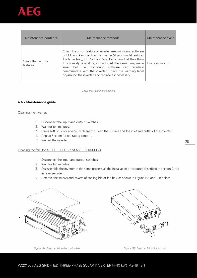
4.4.2 Maintenance guide
Cleaning the inverter:
1. Disconnect the input and output switches. 2. Wait for ten minutes. 3. Use a soft brush or a vacuum cleaner to clean the surface and the inlet and outlet of the inverter. 4. Repeat Section 4.1 operating content. 5. Restart the inverter.
Cleaning the fan (for AS-IC01-8000-2 and AS-IC01-10000-2)
1. Disconnect the input and output switches. 2. Wait for ten minutes. 3. Disassemble the inverter in the same process as the installation procedures described in section 4, but
in reverse order 4. Remove the screws and covers of cooling bin or fan box, as shown in Figure 15A and 15B below.
Figure 15A: Disassembling the cooling bin Figure 15B: Disassembling the fan box
29
PD201809 AEG GRID-TIED THREE-PHASE SOLAR INVERTER (4-10 kW) V.2-18 EN
29
5. Clean the inverter cooling bin and fan with a soft brush or vacuum cleaner. 6. Install the screws and covers of cooling bin or fan box back to their original place 7. Install the inverter to its original place according to section 3. 8. Repeat the operations in section 4.1 9. Restart the inverter.
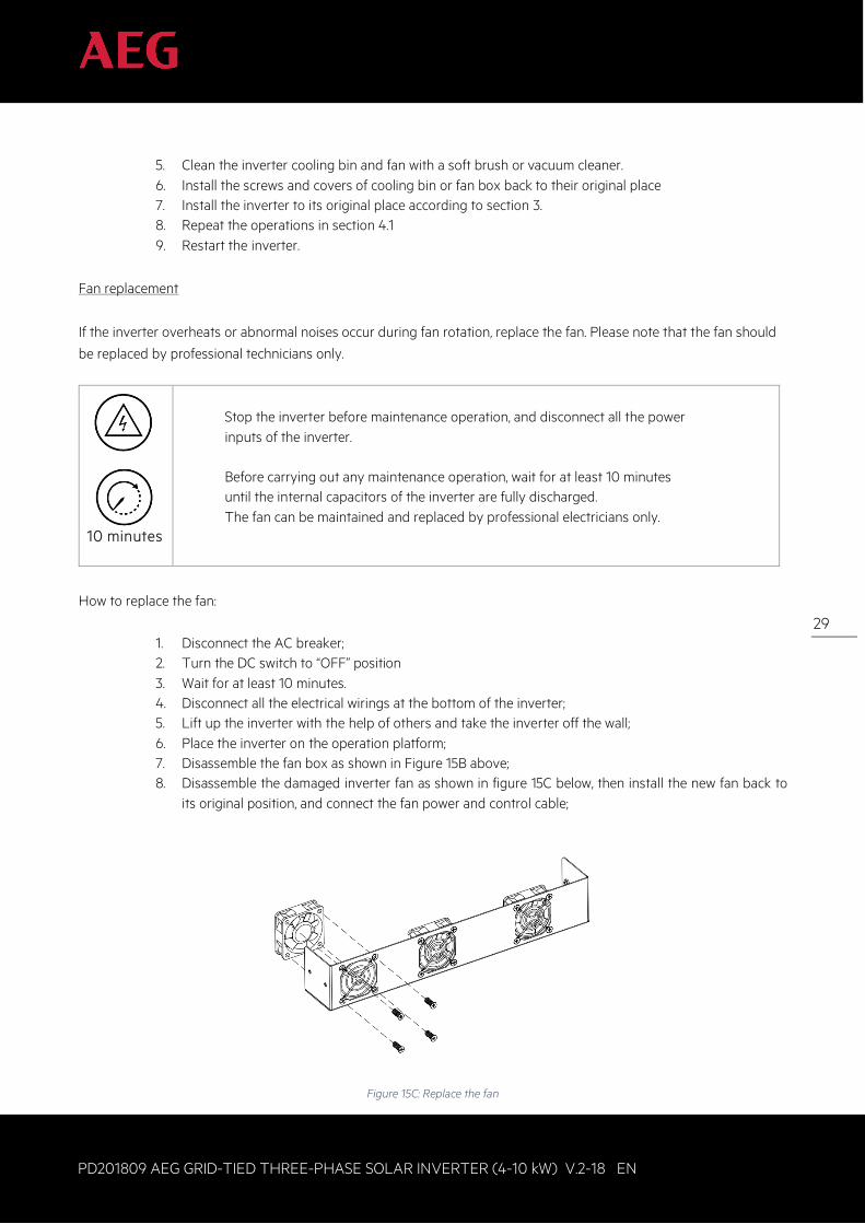
Fan replacement
If the inverter overheats or abnormal noises occur during fan rotation, replace the fan. Please note that the fan should
be replaced by professional technicians only.
10 minutes
Stop the inverter before maintenance operation, and disconnect all the power inputs of the inverter. Before carrying out any maintenance operation, wait for at least 10 minutes until the internal capacitors of the inverter are fully discharged. The fan can be maintained and replaced by professional electricians only.
How to replace the fan:
1. Disconnect the AC breaker; 2. Turn the DC switch to “OFF” position 3. Wait for at least 10 minutes. 4. Disconnect all the electrical wirings at the bottom of the inverter; 5. Lift up the inverter with the help of others and take the inverter off the wall; 6. Place the inverter on the operation platform; 7. Disassemble the fan box as shown in Figure 15B above; 8. Disassemble the damaged inverter fan as shown in figure 15C below, then install the new fan back to
its original position, and connect the fan power and control cable;
Figure 15C: Replace the fan
30
PD201809 AEG GRID-TIED THREE-PHASE SOLAR INVERTER (4-10 kW) V.2-18 EN
30
9. Install the screws and coversof cooling bin or fan box to their original position;
10. Install the inverter to its original position again according to section 3.
11. Repeat the operation in section 4.1
12. Restart the inverter.
Do not start the inverter immediately it if alarms and stops. Figure out the cause
And confirm all the faults are removed before starting the inverter again. Inspections
Should be carried out in strict accordance with the procedures in section 4.1
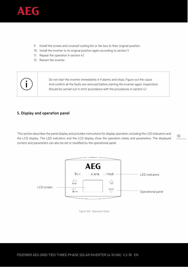
5. Display and operation panel
This section describes the panel display and provides instructions for display operation, including the LED indicators and the LCD display. The LED indicators and the LCD display show the operation states and parameters. The displayed content and parameters can also be set or modified by the operational panel.
Figure 16A: Operation Panel
LCD screen
LED indicators
Operational panel
31
PD201809 AEG GRID-TIED THREE-PHASE SOLAR INVERTER (4-10 kW) V.2-18 EN
31
5.1 LED indicators
There are three LED indicators on the panel:
1. “Run”, operation indicator, green; 2. “Warn” recoverable fault indicator, yellow; 3. “Fault”, unrecoverable fault indicator, red.
The inverter state includes 6 states of stand-by, self-inspection, power generation, recoverable fault and unrecoverable fault; LED indicators are on, off and blinking. Please refer to table 5-1 for detailed state of inverter and LED indicators state.
“ ”: LED indicator is off; “ ” (green), “ ” (yellow), “ ” (red): LED indicator is blinking at every 0.25S or 0.5S; “ (Green), “ ” (yellow), “ ” (red): LED indicator is on.
Inverter state
LED indicators Description
Stand-by RunWarnFault
All indicators are off: No power on
Self-inspection RunWarnFault
Green indicator blinks in every 0.25s, others off: Power on and ready for self-inspection
Power generation
RunWarnFault
Green indicator is on, others off. The inverter is running and grid-tied power is generated)
RunWarnFault
Green and yellow indicators are on, others are off: (1) Grid-tied power generation, but clock fault (A007); (2) Grid-tied power generation, but DC input fault (A001 or E001); (3) Grid-tied power generation, but fan fault (E006 or E012);
Recoverable fault
RunWarnFault
Yellow indicator blinks every 0.5s, others are off: Inverter stand-by. Public grid fault (A001, A003, A004, A005or A006);
RunWarnFault
Yellow indicator is on, others are off: (1) Inverter stand-by. Temperature abnormal(E006); (2) Inverter stand-by. DC input fault (E001);
Unrecoverable fault RunWarnFault
Red indicator blinks every 0.5s, others are off:
32
PD201809 AEG GRID-TIED THREE-PHASE SOLAR INVERTER (4-10 kW) V.2-18 EN
32
Inverter state
LED indicators Description
Hardware or software fault (E003, E004, E005, E008, E009, E011, E013 or E015). De-couple the inverter from the system before maintenance.
RunWarnFault
Red indicator is on, others are off : Current-leakage or unqualified output power energy of the inverter (E007, E010, E014, E017, E018 or E020). De-couple the inverter from the system before maintenance.
Manual turn off RunWarnFault
All indicators are on: Stop after the communication or panel command.
Please refer to chapter 5 and 7 for detailed fault information and troubleshooting.
Table 15: Inverter states
5.2 Operation panel
There are 4 buttons on the panel:
1. “ESC”, exit and return ; 2. “ ”, back to the front page and data increasing; 3. “ ”,to the next page and data decreasing; 4. “ENT”, enter.
5.3 LCD screen All relevant information and parameters can be accessed from the LCD screen. The background illumination of the LCD screen will dim out for power saving upon 15 seconds of inactivity. It can be activated again by pressing any button. Press “ENT” to access the main interface when the background illumination is on.
The main interface appears by default when the inverter is powered on. The individual menu interfaces can be accessed for monitoring data, for setting different parameters and for carrying out other manual operations. Individual menu interfaces allow you to view the monitoring parameters and record history, to access system information, statistics and
faults information, to set the display language, time, communication address and password, and to change the inverter back to factory settings among others.
Text Parameter Display Area
Fault Code MenuStatus Area
Curve Graphic Display Area
Figure 16B: Main interface
33
PD201809 AEG GRID-TIED THREE-PHASE SOLAR INVERTER (4-10 kW) V.2-18 EN
33
Figure 16B above shows the main interface of the LCD screen. The LCD screen displays the following items:
1. Curve. The curve displays the power generation on the current day;
2. Key parameters of the inverter: three lines of words are displayed at a time, but if the inverter is in opera-tion or stand-by state, the words are rolling forward in 3s interval. The user can press “ ” or “ ” to look up the desired information;
3. Status Area: displays the current running state of the inverter, which can be “Self-inspection”, “Grid-connected power generation”, “Alarm”, “Fault” and “OFF” state;
4. Fault Codes. If the inverter is in fault or warning state, up to 8 fault codes can be displaying on the screen.
5.4 Functions operation
Most of the parameters can be viewed and set through the LCD screen and operation panel.
M a i n M e n uM o n i t P a r a mS t a t i s t i c sS e t u pS y s t e m I n f oF a u l t I n f o
Figure 16C: Main interface
5.4.1 Monitoring parameters Press “ ” and “ ” in the main interface to select Monitoring Parameters (“Monit Param”), and then press “ENT” to view the parameters shown in figure 16D. Go the front or next window through “ ” and “ ” and return through “ESC”.
C u r r e n t S t a t eE - t o d : 0 W h$ - t o d : €0 . 0 0P - i n : 0 . 0 0 k W
Figure 16D: Monitoring parameters
5.4.2 History Press “ ” and “ ” in the main interface to select “History”; press “ENT” to view the parameters shown in figure 16E.
H i s t o r y 02 0 1 2 / 0 1 / 0 5 1 1 : 3 2 : 1 6A 0 0 5 : G r i d u n d e r f r e q
Figure 16E: History parameters
In total there are 32 history records. Press “ ” and “ ” to review the history record and press “ESC” to exit. The numbers displayed on the top right is the serial number of the record. The numbers displayed in the second line show
34
PD201809 AEG GRID-TIED THREE-PHASE SOLAR INVERTER (4-10 kW) V.2-18 EN
34
the date when faults occurred and were settled. If the third line is highlighted in color, it means that fault is still occurring. If not,it means that the fault is solved. 5.4.3 Statistics Press “ ” and “ ” in the main interface to select “Statistics”, and then press “ENT” to view the parameters shown in figure 16F.
Figure 16F: Statistic information
The below information can be viewed from the Statistics menu: Statistics menu:
Content
Detail
Lifetime Total operation time, total power produced, total power saved, total CO2 reduction
Day statistics Total power produced, total power saved, peak power and total CO2 reduction in current day
Table 16: Statistical menu
5.4.4 Parameter settings Press “ ” and “ ” in the main interface to select “Setup Menu”, and then press “ENT” to view the parameters shown in figure 16G.
S e t u p M e n uA d d r e s sC a s h / p r i c eD a t e / T i m eL a n g u a g e
Figure 16G: Statistic information
35
PD201809 AEG GRID-TIED THREE-PHASE SOLAR INVERTER (4-10 kW) V.2-18 EN
35
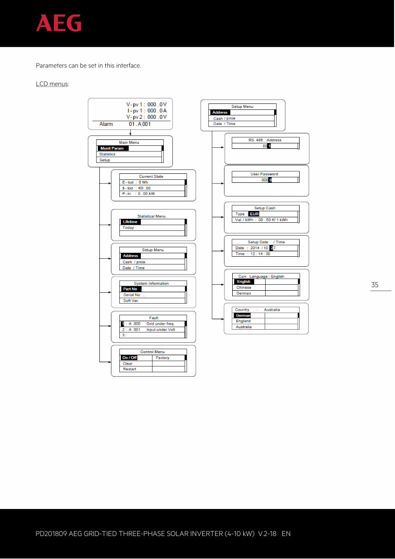
Parameters can be set in this interface. LCD menus:
36
PD201809 AEG GRID-TIED THREE-PHASE SOLAR INVERTER (4-10 kW) V.2-18 EN
36
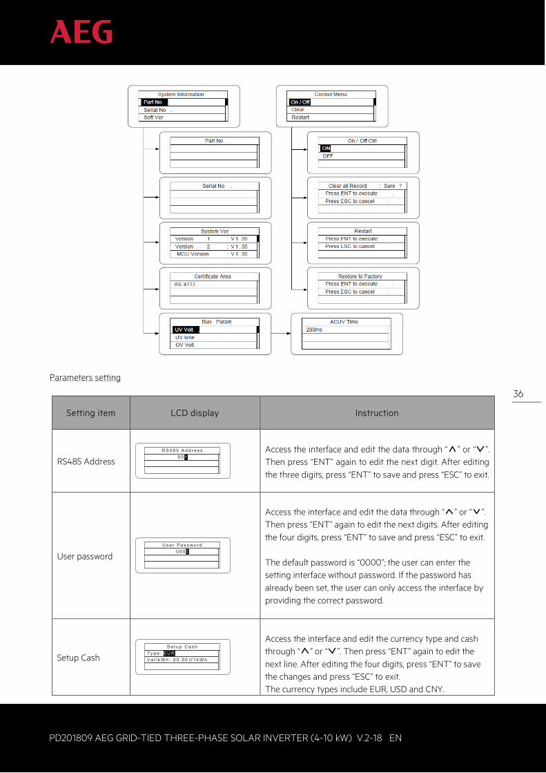
Parameters setting
Setting item
LCD display Instruction
RS485 Address R S 4 8 5 A d d r e s s
0 0 11
Access the interface and edit the data through “ ” or “ ”. Then press “ENT” again to edit the next digit. After editing the three digits, press “ENT” to save and press “ESC” to exit.
User password U s e r P a s s w o r d
0 0 0 00
Access the interface and edit the data through “ ” or “ ”. Then press “ENT” again to edit the next digits. After editing the four digits, press “ENT” to save and press “ESC” to exit. The default password is “0000”; the user can enter the setting interface without password. If the password has already been set, the user can only access the interface by providing the correct password.
Setup Cash S e t u p C a s h
T y p e : E U RV a l / k W h : 0 0 . 5 0€/ 1 k W h
E U R
Access the interface and edit the currency type and cash through “ ” or “ ”. Then press “ENT” again to edit the next line. After editing the four digits, press “ENT” to save the changes and press “ESC” to exit. The currency types include EUR, USD and CNY.
37
PD201809 AEG GRID-TIED THREE-PHASE SOLAR INVERTER (4-10 kW) V.2-18 EN
37
Setting item
LCD display Instruction
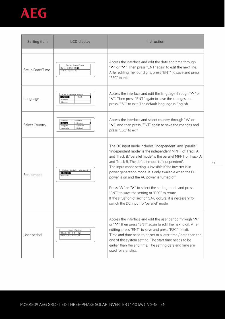
Setup Date/Time S e t u p D a t e / T i m e
D a t e : 2 0 1 2 / 0 1 / 1 5T i m e : 1 2 : 1 4 : 3 0
1
Access the interface and edit the date and time through “ ” or “ ”. Then press “ENT” again to edit the next line. After editing the four digits, press “ENT” to save and press “ESC” to exit.
Language Curr. Language : English
EnglishChineseGerman
Dutch
Access the interface and edit the language through “ ” or “ ”. Then press “ENT” again to save the changes and press “ESC” to exit. The default language is English.
Select Country Country : AustraliaGermanyEnglandAustralia
GreeceDenmarkHolland
Access the interface and select country through “ ” or “ ”. And then press “ENT” again to save the changes and press “ESC” to exit.
Setup mode S e t u p M o d e l : I n d e p e n d
I n d e p e n dP a r a l l e l
The DC input mode includes “independent” and “parallel”: “independent mode” is the independent MPPT of Track A and Track B; “parallel mode” is the parallel MPPT of Track A and Track B. The default mode is “independent”. The input mode setting is invisible if the inverter is in power generation mode. It is only available when the DC power is on and the AC power is turned off Press “ ” or “ ” to select the setting mode and press “ENT” to save the setting or “ESC” to return. If the situation of section 5.4.8 occurs, it is necessary to switch the DC input to “parallel” mode.
User period U s e r P e r i o d
S t a r t : 2 0 1 2 - 0 1 - 0 1E n d : 2 0 1 2 - 0 2 - 0 1
1
Access the interface and edit the user period through “ ” or “ ”, then press “ENT” again to edit the next digit. After editing, press “ENT” to save and press “ESC” to exit. Time and date need to be set to a later time / date than the one of the system setting. The start time needs to be earlier than the end time. The setting date and time are used for statistics.
38
PD201809 AEG GRID-TIED THREE-PHASE SOLAR INVERTER (4-10 kW) V.2-18 EN
38
Setting item
LCD display Instruction
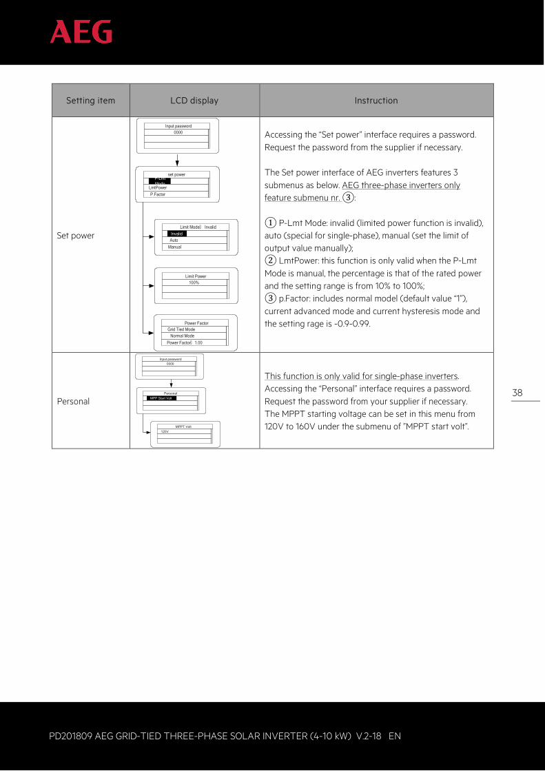
Set power
set powerP-Lmt Mode
LmtPowerP.Factor
Limit Mode: InvalidInvalid
AutoManual
Limit Power100%
Power FactorGrid Tied Mode
Normal ModePower Factor: 1.00
Input password0000
Accessing the “Set power” interface requires a password. Request the password from the supplier if necessary. The Set power interface of AEG inverters features 3 submenus as below. AEG three-phase inverters only feature submenu nr. ③: ① P-Lmt Mode: invalid (limited power function is invalid), auto (special for single-phase), manual (set the limit of output value manually); ② LmtPower: this function is only valid when the P-Lmt Mode is manual, the percentage is that of the rated power and the setting range is from 10% to 100%; ③ p.Factor: includes normal model (default value “1”), current advanced mode and current hysteresis mode and the setting rage is -0.9-0.99.
Personal Personal
MPP Start Volt
MPPT Volt120V
Input password0000
This function is only valid for single-phase inverters. Accessing the “Personal” interface requires a password. Request the password from your supplier if necessary. The MPPT starting voltage can be set in this menu from 120V to 160V under the submenu of ”MPPT start volt”.
39
PD201809 AEG GRID-TIED THREE-PHASE SOLAR INVERTER (4-10 kW) V.2-18 EN
39
Setting item
LCD display Instruction
Run Param
Run ParamUV VoltUV timeOV Volt
OV timeUF FreqUF time
ACUV Volt(phase volt)184V
ACUV Time0.20s
ACOV Volt(phase volt)263V
ACOV Time0.20s
ACUF Freqency47.6Hz
ACUF Time0.20s
ACOF Freqency51.4Hz
ACOF Time0.20s
Input password0000
Accessing the “Run Param” interface requires a password. Request the password from your supplier if necessary. Set ACUV Volt, ACUV time etc. under the related submenus, press “ ” and “ ” to modify, and press “ENT” to confirm.
40
PD201809 AEG GRID-TIED THREE-PHASE SOLAR INVERTER (4-10 kW) V.2-18 EN
40
Setting item
LCD display Instruction
Run Param*
Run ParamUV volt 1
UV time 1OV volt 1
OV time 1UF Freq 1UF time 1
ACUV Volt(phase volt)115V
ACUV Time00.04s
309V
00.02s
ACUF Frequency47.99Hz
00.12s
50.50hz
00.12s
·
Input Password0000
196V
252V
0.19s
01.90s
49.49Hz
595s
50.2Hz
115s
Run Restart Time060s
Island protect:onOFFON
ACOV Volt(phase volt)
ACOV Time
ACUF Time
ACOF Frequency
ACOF Time
ACUV Volt(phase volt)
ACUV Time
ACOV Volt(phase volt)
ACOV Time
ACUF Frequency
ACUF Time
ACOF Frequency
ACOF Time
There are 2 protections under G83/G59 (UK) and PEA (Thailand) standards, and there is only one protection under other grid tied standard. Set ACUV Volt, ACUV time etc. under the related submenus, press “ ” and “ ” to modify, and press “ENT” to confirm. Generally, it is only necessary to set ACUV and ACUF value for ACUV and ACUF protection. It is necessary to set ACOF1 and ACOF2 together for ACOF protection.
Table 18: Parameter settings
41
PD201809 AEG GRID-TIED THREE-PHASE SOLAR INVERTER (4-10 kW) V.2-18 EN
41
5.4.5 System Information Press “ ” and “ ” in the main interface to select “System Information”, and then press “ENT” to view the parameters shown in figure 16H.
System InformationPart No .Serial No .Soft Ver
Figure 16H: System information
The system information include product model, serial number (serial No), software version and certificate version. If you select “Software version” in the “System version”, you will be able to see inverter Version 1, Version 2, MCU software version, RS485 protocol and other information as shown in picture 16I below.
S y s t e m V e rV e r s i o n 1 : V 1 . 0 5V e r s i o n 2 : V 1 . 0 5M C U V e r s i o n : V 1 . 0 5
Figure 16I: System version
5.4.6 Faults Press “ ” and “ ” in the main interface to review the fault history, and then press “ENT” to view the sub-menu shown in figure 16J.
F a u l t1 : A 0 0 5 G r i d u n d e r f r e q2 : A 0 0 1 I n p u t u n d e r V o l t3 :
1
Figure 16J: Fault information
There are maximal 8 fault information logs in the record shown in figure 16J; if no faults are present, the system will display the message “No Fault”. Refer to section 5.4.2 for detailed information. 5.4.7 Inverter control Press “ ” and “ ” in the control interface, and then press “ENT” to view the sub-menu shown in figure 16K.
C o n t r o l M e n uO n / O f fC learR e s t a r t
F a c t o r y
Figure 16K: Control interface
42
PD201809 AEG GRID-TIED THREE-PHASE SOLAR INVERTER (4-10 kW) V.2-18 EN
42
Refer to the below table for detailed information. Inverter control
Control item
LCD display Instruction
On/Off control O n / O f f C t r l
O NO F F
Control the “On/Off” function through the panel. Press “ ” and “ ” in the control interface to select the operation. Press “ENT” to confirm the operation and press “ESC” to return.
Restart R e s t a r t
P r e s s E N T t o e x e c u t e .P r e s s E S C t o c a n c e l .
Restart the inverter through the panel. All settings and operation record will be saved. Press “ENT” to confirm restarting: the inverter will begin to self-inspect; or press “ESC” to return.
Record clear C l e a r a l l R e c o r d : S u r e?
P r e s s E N T t o e x e c u t e .P r e s s E S C t o c a n c e l .
Press “ENT” to confirm clearing all records or press “ESC” to return. “Record clear” clears all setting parameters through the panel, restores the factory settings and saves all history operation records.
Restore to factory
R e s t o r e t o F a c t o r yP r e s s E N T t o e x e c u t e .P r e s s E S C t o c a n c e l .
“Restore to factory” clears all setting parameters and history operation records through the panel and restores the factory setting. Press “ENT” to confirm the operation or press “ESC” to return.
Table 19: Inverter control
43
PD201809 AEG GRID-TIED THREE-PHASE SOLAR INVERTER (4-10 kW) V.2-18 EN
43
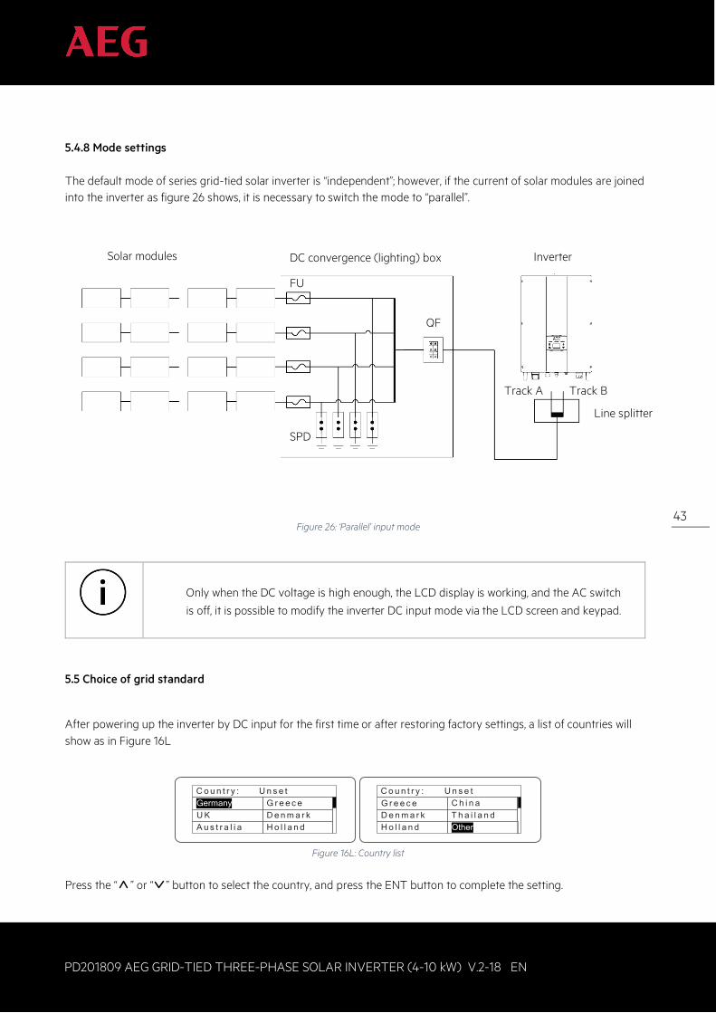
5.4.8 Mode settings The default mode of series grid-tied solar inverter is “independent”; however, if the current of solar modules are joined into the inverter as figure 26 shows, it is necessary to switch the mode to “parallel”.
Figure 26: ‘Parallel’ input mode
Only when the DC voltage is high enough, the LCD display is working, and the AC switch
is off, it is possible to modify the inverter DC input mode via the LCD screen and keypad.
5.5 Choice of grid standard
After powering up the inverter by DC input for the first time or after restoring factory settings, a list of countries will show as in Figure 16L
C o u n t r y : U n s e tGermanyU KA u s t r a l i a
G r e e c eD e n m a r kH o l l a n d
C o u n t r y : U n s e t
OtherD e n m a r kH o l l a n d
C h i n aT h a i l a n d
G r e e c e
Figure 16L: Country list
Press the “ ” or “ ” button to select the country, and press the ENT button to complete the setting.
Solar modules DC convergence (lighting) box
SPD
FU
Inverter
QF
Track A Track B
Line splitter
44
PD201809 AEG GRID-TIED THREE-PHASE SOLAR INVERTER (4-10 kW) V.2-18 EN
44
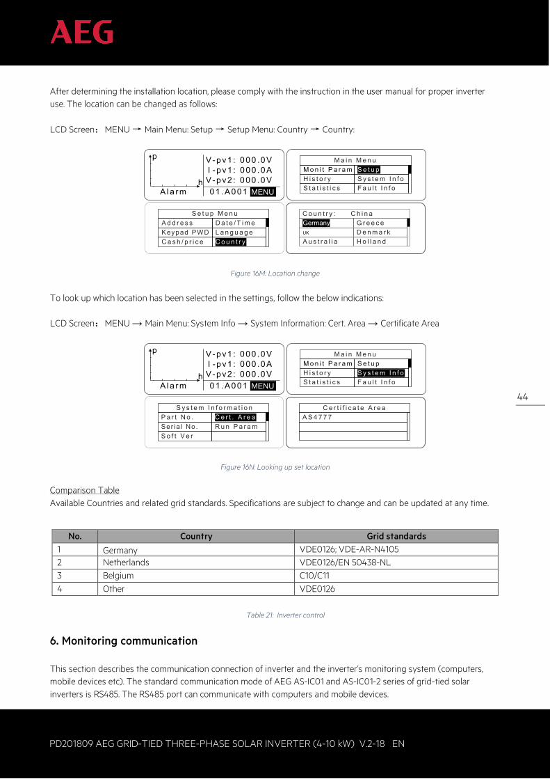
After determining the installation location, please comply with the instruction in the user manual for proper inverter use. The location can be changed as follows: LCD Screen:MENU → Main Menu: Setup → Setup Menu: Country → Country:
V-pv1 : 000 .0V I - pv1 : 000 .0AV-pv2 : 000 .0V01 .A001MENUAla rm
p
hMENU
M a i n M e n uM o n i t P a r a mH i s t o r yS t a t i s t i c s
S e t u pS y s t e m I n f oF a u l t I n f o
S e t u p M e n uA d d r e s sKeypad PWDC a s h / p r i c e
D a t e / T i m eL a n g u a g eC o u n t r y
C o u n t r y : C h i n aGermanyUK
A u s t r a l i a
G r e e c eD e n m a r kH o l l a n d
Figure 16M: Location change
To look up which location has been selected in the settings, follow the below indications: LCD Screen:MENU → Main Menu: System Info → System Information: Cert. Area → Certificate Area
V-pv1 : 000 .0V I - pv1 : 000 .0AV-pv2 : 000 .0V01 .A001MENUAla rm
p
hMENU
M a i n M e n uM o n i t P a r a mH i s t o r yS t a t i s t i c s
S e t u pS y s t e m I n f oF a u l t I n f o
S y s t e m I n f o r m a t i o nP a r t N o .Ser ia l No .S o f t V e r
C e r t . A r e aR u n P a r a m
C e r t i f i c a t e A r e aA S 4 7 7 7
Figure 16N: Looking up set location Comparison Table Available Countries and related grid standards. Specifications are subject to change and can be updated at any time.
No. Country Grid standards 1 Germany
VDE0126; VDE-AR-N4105
2 Netherlands VDE0126/EN 50438-NL 3 Belgium C10/C11 4 Other VDE0126
Table 21: Inverter control
6. Monitoring communication This section describes the communication connection of inverter and the inverter’s monitoring system (computers, mobile devices etc). The standard communication mode of AEG AS-IC01 and AS-IC01-2 series of grid-tied solar inverters is RS485. The RS485 port can communicate with computers and mobile devices.
45
PD201809 AEG GRID-TIED THREE-PHASE SOLAR INVERTER (4-10 kW) V.2-18 EN
45
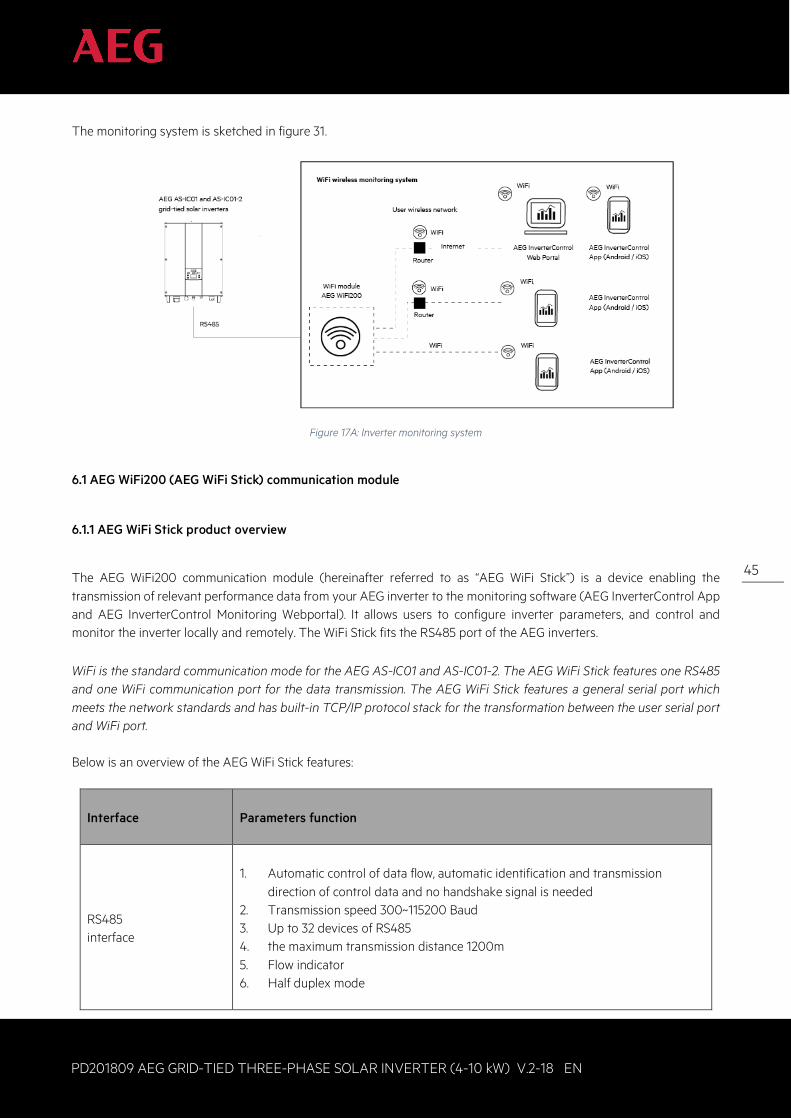
The monitoring system is sketched in figure 31.
Figure 17A: Inverter monitoring system
6.1 AEG WiFi200 (AEG WiFi Stick) communication module
6.1.1 AEG WiFi Stick product overview
The AEG WiFi200 communication module (hereinafter referred to as “AEG WiFi Stick”) is a device enabling the transmission of relevant performance data from your AEG inverter to the monitoring software (AEG InverterControl App and AEG InverterControl Monitoring Webportal). It allows users to configure inverter parameters, and control and monitor the inverter locally and remotely. The WiFi Stick fits the RS485 port of the AEG inverters. WiFi is the standard communication mode for the AEG AS-IC01 and AS-IC01-2. The AEG WiFi Stick features one RS485 and one WiFi communication port for the data transmission. The AEG WiFi Stick features a general serial port which meets the network standards and has built-in TCP/IP protocol stack for the transformation between the user serial port and WiFi port. Below is an overview of the AEG WiFi Stick features:
Interface
Parameters function
RS485 interface
1. Automatic control of data flow, automatic identification and transmission
direction of control data and no handshake signal is needed 2. Transmission speed 300~115200 Baud 3. Up to 32 devices of RS485 4. the maximum transmission distance 1200m 5. Flow indicator 6. Half duplex mode
46
PD201809 AEG GRID-TIED THREE-PHASE SOLAR INVERTER (4-10 kW) V.2-18 EN
46
Interface
Parameters function
WiFi interface
1. Supports data exchange between RS485 - WiFi interface 2. Meets the 802.11 b/g/n wireless standard 3. Wireless network AP/STA 4. Security mechanism WEP/WPA-PSK/WPA2-PSK/WAPI 5. Barrier-free transmission distance 100 m
Others
1. TCP Server, TCP Client, UDP mode and UDP Server mode 2. Operation interface, target IP address and interface can be set in random 3. Disconnect automatically after network disconnection, ensures reliable TCP
connection of the whole network 4. Supports TCP/IP/UDP network protocol stack 5. IE configuration interface 6. Operation mode, Transparent data transmission or agreement transfer mode 7. Input power supply: 5VDC~12V/170mA~300mA ; powered directly by
the inverter 8. Working temperature: -20~70°C 9. Working humidity:10%-90%RH (no condensation) 10. Storage temperature: -40-80 °C 11. Storage humidity: 5%-90%RH (no condensation) 12. Other frequency: 20MHz, 40MHz and automatic
Table 23: AEG WiFi Stick features
The AEG WiFi Stick is released from factory in AP mode. It can be connected with the 485 communication interface of inverters and can be operated over computer or mobile software.
6.1.2 Remote Monitoring and Local Monitoring; the AEG InverterControl App and Portal
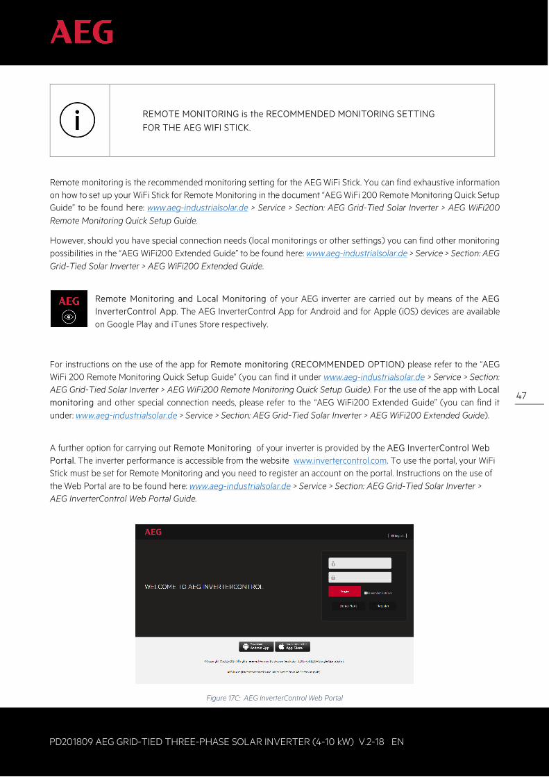
There are two modes with which the AEG WiFi Stick allows you to monitor your inverter: Remote monitoring and Local Monitoring.
Remote Monitoring allows you to monitor your AEG inverter from any place you have a mobile internet connection. Monitoring takes place via mobile (via the AEG InverterControl App) or via PC (via the AEG InverterControl Webportal).
Local Monitoring allows you to connect directly to one individual inverter without using an internet connection. As you connect directly to the inverter, you will not be able to monitor its data when you lose connection to it. (e.g. when you leave the house).
47
PD201809 AEG GRID-TIED THREE-PHASE SOLAR INVERTER (4-10 kW) V.2-18 EN
47
REMOTE MONITORING is the RECOMMENDED MONITORING SETTING
FOR THE AEG WIFI STICK.
Remote monitoring is the recommended monitoring setting for the AEG WiFi Stick. You can find exhaustive information on how to set up your WiFi Stick for Remote Monitoring in the document “AEG WiFi 200 Remote Monitoring Quick Setup Guide” to be found here: www.aeg-industrialsolar.de > Service > Section: AEG Grid-Tied Solar Inverter > AEG WiFi200 Remote Monitoring Quick Setup Guide.
However, should you have special connection needs (local monitorings or other settings) you can find other monitoring possibilities in the “AEG WiFi200 Extended Guide” to be found here: www.aeg-industrialsolar.de > Service > Section: AEG Grid-Tied Solar Inverter > AEG WiFi200 Extended Guide.
Remote Monitoring and Local Monitoring of your AEG inverter are carried out by means of the AEG InverterControl App. The AEG InverterControl App for Android and for Apple (iOS) devices are available on Google Play and iTunes Store respectively.
For instructions on the use of the app for Remote monitoring (RECOMMENDED OPTION) please refer to the “AEG WiFi 200 Remote Monitoring Quick Setup Guide” (you can find it under www.aeg-industrialsolar.de > Service > Section: AEG Grid-Tied Solar Inverter > AEG WiFi200 Remote Monitoring Quick Setup Guide). For the use of the app with Local monitoring and other special connection needs, please refer to the “AEG WiFi200 Extended Guide” (you can find it under: www.aeg-industrialsolar.de > Service > Section: AEG Grid-Tied Solar Inverter > AEG WiFi200 Extended Guide).
A further option for carrying out Remote Monitoring of your inverter is provided by the AEG InverterControl Web Portal. The inverter performance is accessible from the website www.invertercontrol.com. To use the portal, your WiFi Stick must be set for Remote Monitoring and you need to register an account on the portal. Instructions on the use of the Web Portal are to be found here: www.aeg-industrialsolar.de > Service > Section: AEG Grid-Tied Solar Inverter > AEG InverterControl Web Portal Guide.
Figure 17C: AEG InverterControl Web Portal
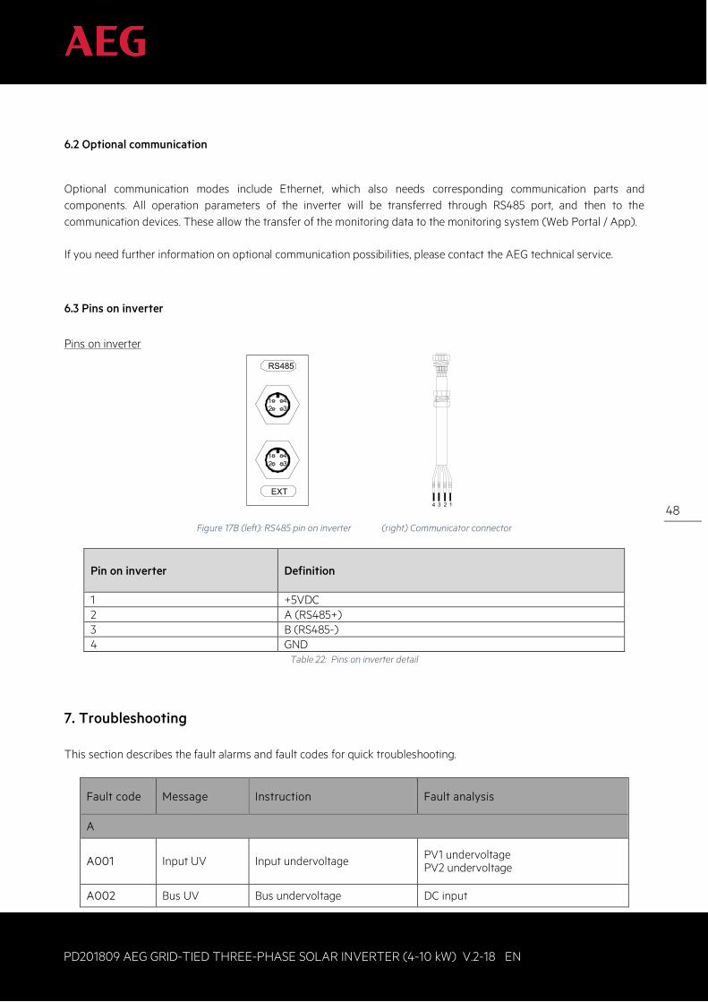
48
PD201809 AEG GRID-TIED THREE-PHASE SOLAR INVERTER (4-10 kW) V.2-18 EN
48
6.2 Optional communication
Optional communication modes include Ethernet, which also needs corresponding communication parts and components. All operation parameters of the inverter will be transferred through RS485 port, and then to the communication devices. These allow the transfer of the monitoring data to the monitoring system (Web Portal / App). If you need further information on optional communication possibilities, please contact the AEG technical service.
6.3 Pins on inverter
Pins on inverter
RS485
EXT
321 4
321 4
1
+5V
485+
485-
GND
234
Figure 17B (left): RS485 pin on inverter (right) Communicator connector
Pin on inverter
Definition
1 +5VDC 2 A (RS485+) 3 B (RS485-) 4 GND
Table 22: Pins on inverter detail
7. Troubleshooting This section describes the fault alarms and fault codes for quick troubleshooting.
Fault code Message Instruction Fault analysis
A
A001 Input UV Input undervoltage PV1 undervoltage PV2 undervoltage
A002 Bus UV Bus undervoltage DC input
49
PD201809 AEG GRID-TIED THREE-PHASE SOLAR INVERTER (4-10 kW) V.2-18 EN
49
Fault code Message Instruction Fault analysis
A003 Grid UV AC undervoltage Low voltage of the public grid
A004 Grid OV AC overvoltage High voltage of the public grid
A005 Grid UF AC underfrequency Low frequency of the public grid
A006 Grid OF AC overfrequency High frequency of the public grid
A007 Clock Fail Clock alarm Wrong setting
A009 Cmd Shut Manual shutdown Stop by the operation panel or upper PC
A011 Grid Loss The public grid disconnects. Check if inverter AC connection is OK
E
E001 Input OV Input overvoltage DC input overvoltage
E003 Bus OV Bus overvoltage Internal bus voltage
E004 Boost Fail Voltage-boost fault Voltage-boost fault of the inverter
E005 Grid OC AC overcurrent Internal AC overcurrent
E006 OTP Overtemperature Internal overtemperature
E007 Riso Low Low isolation impedance Low isolation impedance of the external port system
E008 IGBT drv IGBT drive protection IGBT drive protection of the inverter
E009 Int Comm Internal communication fault Master-slave DSP communication disabled Error of master-slave DSP check bit
E010 Leek Fail Huge leakage current Huge leakage current of the system or inverter
E011 Relay Fault Relay fault Internal relay fault
E012 Fan Fail Fan fault Internal fan fault
E013 Eeprom Memory error Internal memory error
E014 Dc inject High DC injection High DC injection during AC output
E015 OutputShort Output short-circuit Output short-circuit
E018 Input OC Input overcurrent DC input overcurrent
E019 Incnst Data consistency fault Inconsistent grid voltage, frequency, leakage current or AC/DC injection
E020 PowerReversed DC power reversed DC power reversed
50
PD201809 AEG GRID-TIED THREE-PHASE SOLAR INVERTER (4-10 kW) V.2-18 EN
50
If any problem occurs, please contact your supplier and provide the following information:
• Inverter model: • Inverter serial number: • System version: version 1: version 2: MCU software version:
• Fault code: • Fault description:
8. Contact Solar Solutions GmbH Schneckenhofstrasse 19 60596 Frankfurt am Main Germany www.aeg-industrialsolar.de Technical Support: Mail: [email protected] Tel: +31 172 205 011
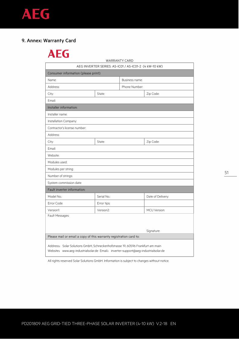
51
PD201809 AEG GRID-TIED THREE-PHASE SOLAR INVERTER (4-10 kW) V.2-18 EN
51
9. Annex: Warranty Card
WARRANTY CARD
AEG INVERTER SERIES: AS-IC01 / AS-IC01-2 (4 kW-10 kW)
Consumer information (please print):
Name: Business name:
Address: Phone Number:
City: State: Zip Code:
Email:
Installer information:
Installer name:
Installation Company:
Contractor’s license number:
Address:
City: State: Zip Code:
Email:
Website:
Modules used:
Modules per string:
Number of strings:
System commission date:
Fault inverter information:
Model No.: Serial No.: Date of Delivery:
Error Code: Error tips:
Version1: Version2: MCU Version:
Fault Messages:
Signature:
Please mail or email a copy of this warranty registration card to:
Address:Solar Solutions GmbH, Schneckenhofstrasse 19, 60596 Frankfurt am main Website:www.aeg-industrialsolar.de Email:[email protected]
All rights reserved Solar Solutions GmbH. Information is subject to changes without notice.

Solar Solutions GmbH Schneckenhofstrasse 1960596 Frankfurt am Main, Germanywww.aeg-industrialsolar.de