Embed Size (px)
Citation preview
PFAFF -900
Thread Trimmer
Special Mechanism for Pfaff 461, 463, 465, 467, 469
and 467/469 High-Speed Seamers
Service Manual and
List of Spare Parts
G.M. PFAFF AG • KAISERSLAUTERN BRANCH
From the library of: Superior Sewing Machine & Supply LLC
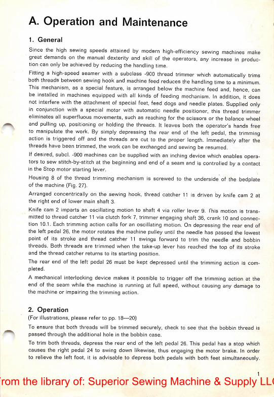
A. Operation and Maintenance
1. General
Since the high sewing speeds attained by modern high-efficiency sewing machines makegreat demands on the manual dexterity and skill of the operators, any increase in production can only be achieved by reducing the handling time.Fitting a high-speed seamer with a subclass -900 thread trimmer which automatically trimsboth threads between sewing hook and machine feed reduces the handling time toa minimum.This mechanism, as a special feature, is arranged below the machine feed and, hence, canbe installed in machines equipped with all kinds of feeding mechanism. In addition, it doesnot interfere with the attachment of special feet, feed dogs and needle plates. Supplied onlyin conjunction with a special motor with automatic needle positioner, this thread trimmereliminates all superfluous movements, such as reaching for the scissors or the balance wheeland pulling up, positioning or holding the threads. It leaves both the operator's hands freeto manipulate the work. By simply depressing the rear end of the left pedal, the trimmingaction is triggered off and the threads are cut to the proper length. Immediately after thethreads have been trimmed, the work can be exchanged and sewing be resumed,ifdesired, subcl. -900 machines can be supplied with an inching device which enables operators to sew stitch-by-stitch at the beginning and end of a seam and is controlled by a contactin the Stop motor starting lever.
Housing 8 of the thread trimming mechanism is screwed to the underside of the bedplateof the machine (Fig. 27).
Arranged concentrically on the sewing hook, thread catcher 11 is driven by knife cam 2 atthe right end of lower main shaft 3.
Knife cam 2 imparts an oscillating motion to shaft A via roller lever 9. fhis motion is transmitted to thread catcher 11 via clutch fork 7, trimmer engaging shaft 36. crank 10 and connection 10.1. Each trimming action calls for an oscillating motion. On depressing the rear end ofthe left pedal 26, the motor rotates the machine pulley until the needle has passed the lowestpoint of its stroke and thread catcher 11 swings forward to trim the needle and bobbinthreads. Both threads are trimmed when the take-up lever has reached the top of its strokeand the thread catcher returns to its starting position.
The rear end of the left pedal 26 must be kept depressed until the trimming action is completed.
A mechanical interlocking device makes it possible to trigger off the trimming action at theend of the seam while the machine is running at full speed, without causing any damage tothe machine or impairing the trimming action.
2. Operation(For Illustrations, please refer to pp. 18—20)
To ensure that both threads will be trimmed securely, check to see that the bobbin thread ispassed through the additional hole in the bobbin case.
To trim both threads, depress the rear end of the left pedal 26. This pedal has a stop whichcauses the right pedal 24 to swing down likewise, thus engaging the motor brake. In orderto relieve the left foot, it is advisable to depress both pedals with both feet simultaneously.
1
From the library of: Superior Sewing Machine & Supply LLC
As the rear end of the left pedal 26 is depressed, connection 27 rotates trimmer engaging
cam 30 which causes a spring to be compressed between the cam and tension releasecone 21. The amount of tension thus accumulated in the spring is sufficient to bring roller 6In engagement with the control slot in knife cam 2. At the same time, pedal 24 actuates limitswitch ES, which is located underneath this pedal and, in conjunction with carbon brushholder 17 and synchronizer siip ring 16, engages the electromagnetic clutch. This clutch connects the motor and the machine via a worm gearing and reduces the machine speed to theproper rate required for the trimming action. Whiie the machine is still running at high speed,centrifugal switch 18 delays the trimmer engaging action until the machine speed has beenreduced to a safe level at which the trimming mechanism is not likely to be damaged.The machine keeps running at this reduced speed until the needle has reached the lowestpoint of its stroke and the left carbon brush in holder 17 contacts the left switch-off trackon slip ring 16. This is the point at which the thread trimming action starts (Fig. 27). Centrifugal switch 18 actuates pin 19 which, in turn, pushes interlocking latch 5 down so that itclears crank 20. This permits shaft 4. together with roller lever 9 and roller 6, to be movedtoward knife cam 2 by action of the released pressure spring, causing roller 6 to engage inthe slot of the cam (Fig. 28).
At the same time, cone 21 releases the needle thread tension and the right carbon brush inholder 17 moves to the right switch-off track of synchronizer slip ring 16. while the motorkeeps driving the machine at low speed. Then knife cam 2 imparts an oscillating motionto roller lever 9 which is transmitted to shaft 4. crank 10, connection 10.1 and thread catcher
11. causing the latter to trim the threads. The machine stops now with the take-up lever atits highest position.
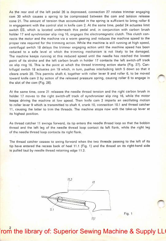
As thread catcher 11 swings forward, its tip enters the needle thread loop so that the bobbinthread and the left leg of the needle thread loop contact its left flank, while the right legof the needle thread loop contacts its right fiank.
The thread catcher ceases to swing forward when the two threads passing to the left of itstip have entered the recess back of heel 11.1 (Fig. 1) and the thread on its right-hand sideis pulled taut by needle thread retaining edge 11.2.
Fig. 1
W
From the library of: Superior Sewing Machine & Supply LLC

As thread catcher t1 returns to its starting position, the threads caught in the recess arepulled back under knife 12. Both threads are protected in a groove on the surface of thethread catcher (Fig. 1) and are not sheared off until the somewhat raised cutting edge S 1 atthe tip of the thread catcher has reached cutting edge S 2 of the knife (Fig. 2).
When the threads are severed, the take-up lever has reached the highest point of its strokeand the right switch-off track of synchronizer siip ring 16 stops the machine. The operatorcan now take her foot off the left pedal. If both pedals were depressed, make sure that bothare permitted to return to their inoperative position simultaneously. It is advisable to let theright pedai return to its starting position slightly ahead of the left because the needle willstart to descend again if the right treadle is not returned to its starting position promptly.
In order to enable operators to switch from forward to backward stitching by foot action on
Pfaff machines 461-900. 463-900 and 465-900, an additional feed reversing mechanism hasbeen mounted on feed regulating shaft (Fig. 27). When the front end of pedal 26 is depressed,connection 27 causes trimmer engaging cam 30 to turn forward and this motion is transmittedto feed reversing crank 33 by means of a two-part connection.
On Pfaff machines 467-900 and 469-900, the top or differential feed can be controlled by depressing the front end of the left pedal. The reverse feed control of these machines must beoperated by hand.
3. Maintenance
A careful adjustment of the trimming mechanism ensures trouble-free operation.
Ail screws must be tightened securely. This applies especially to the screws on knife cam 2,roller lever 9 and thread catcher driving crank 10 since these parts are subjected to abruptstress.
Special care should be taken that the dust and lint which accumulate in this mechanism,especially between sewing hook and needle plate, are removed with a soft brush each daythe machine is in operation. By the same token, ail moving parts should be oiled daily.
When oiling all moving parts of the trimming mechanism each day, check to see that centrifugal switch 18, pin 19 and latch 5 move freely. Make particularly sure that synchronizerslip ring 16 is kept free from oil.
Be sure to oil the somewhat concealed roller 6 on roller lever 9.
From the library of: Superior Sewing Machine & Supply LLC

B. Adjustment
It is recommended to use a gauge needle plate 14 (Fig. 30) for the adjustment of the threadcatcher which is available under No. 129 499. A gauge feed dog, which is identified byNo. 129 567, can be supplied for compound-feed machines.
In checking the various settings, be sure to proceed in the sequence indicated below:
1. Adjusting the Interlocking Latch
Raise the needle to its highest point and disengage the thread trimmer (trimmer engagingcam 30 in its inoperative position).
Push trimmer engaging shaft 4 to the right by pressing against carbon brush holder 17 withyour thumb, and check whether interlocking latch 5 fits over crank 20 securely. There shouldbe a clearance of about .004", or 0.1 mm, between interlocking latch 5 and drivingcrank 20 (Fig. 3). Adjustment is made by eccentric roller stud 31 which engages in the slot oftrimmer engaging cam 30. After the adjustment, check to see that there is a clearance ofabout .04", or 1.0 mm, between the face of eccentric roller stud 31 and the bottom of the
slot in trimmer engaging cam 30 (Fig. 4).
j©l
Fig. 3 Fig. 4
From the library of: Superior Sewing Machine & Supply LLC

2. Endwise Adjustment of Knife Cam
Set knife cam 2 on lower main shaft 3 so that there is a clearance of about .02", or 0.5 mm,between knife cam and bedplate (Fig. 5). After this adjustment, check to see that the slipwasher contacts the knife cam hub.
O.Smm
Fig. 5
When the needle Is at its lowest point, the pointed lobe of knife cam 2 should point towardthe lower front edge of the bedplate (Fig. 6).
a/ oT^
Fig. 6
From the library of: Superior Sewing Machine & Supply LLC

3. Adjusting the Roller Lever
Raise the needle to its highest point and disengage the thread trimmer (trimmer engagingcam 30 in its inoperative position).
Move roller lever 9 to the right on trimmer engaging shaft 4 until roller 6 contacts the recessed inner surface of knife cam 2, and mark this position on trimmer engaging shaft 4(Fig. 7).
Bring the needle to its lowest position.
Engage roller lever 9 in the slot of knife cam 2 and rotate trimmer engaging cam 30 untilits stud contacts set screw 29 of stop 28 (Fig. 28). Push roller lever 9 to the left until theabove-mentioned mark becomes visible on trimmer engaging shaft 4. Continue pushing untilroller lever 9 is positioned about 02", or 0.5 mm, beyond this mark. Pull out thread catcherdriving crank 10 as far as it will go and hold it there. Push roller lever 9 against the outerwall of the slot in knife cam 2 and tighten its set screws securely.
Fig. 7 Fig. 8
From the library of: Superior Sewing Machine & Supply LLC

4. Double-checking Adjustments 1-3
Bring the needle to its lowest position. As you rotate trimmer engaging cam 30 in eitherdirection, the roller of roller lever 9 should fit into the slot of knife cam 2 easily, withoutmaking any radial movement.
Raise the needle to its highest point. Hold interlocking latch 5 steady and turn trimmerengaging cam 30 until its stud contacts stop 28. As you turn the balance wheel, there shouldbe a clearance of .02", or 0.5 mm, between the roller on roller lever 9 and the recessed inner
surface of knife cam 2 (Fig. 9).
Bring the needle to its highest point and turn trimmer engaging cam 30 to its inoperativeposition. Insert roller lever 9 into the sharp bend of the slot of knife cam 2 and check whetherthe roller lever returns to its starting position as you rotate the balance wheel. When atthis position, the roller should still be about .06", or 1.5 mm, inside the slot of knife cam 2(Fig. 10). Make sure the clearance between guide fork 17.1 and carbon brush holder 17does not exceed .004"—.008", or 0.1—0.2 mm (Fig. 29).
Fig. 9 Fig. 10 ]Sfnm
From the library of: Superior Sewing Machine & Supply LLC
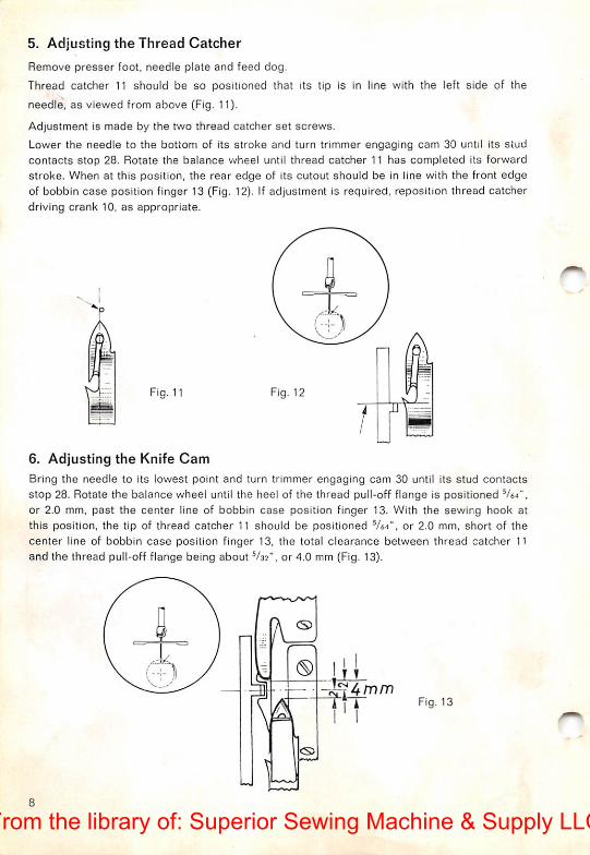
5. Adjusting the Thread Catcher
Remove presser foot, needle plate and feed dog.
Thread catcher 11 should be so positioned that its tip is in line with the left side of the
needle, as viewed from above (Fig. 11).
Adjustment is made by the two thread catcher set screws.
Lower the needle to the bottom of its stroke and turn trimmer engaging cam 30 until its stud
contacts stop 28. Rotate the balance wheel until thread catcher 11 has completed its forwardstroke. When at this position, the rear edge of its cutout should be in line with the front edgeof bobbin case position finger 13 (Fig. 12). If adjustment is required, reposition thread catcherdriving crank 10. as appropriate.
Fig. 11 Fig. 12>•
i
/ •
6. Adjusting the Knife CamBring the needle to its lowest point and turn trimmer engaging cam 30 until its stud contactsstop 28. Rotate the balance wheel until the heel of the thread pull-off flange is positioned Vti".or 2.0 mm, past the center line of bobbin case position finger 13. With the sewing hook atthis position, the tip of thread catcher 11 should be positioned or 2.0 mm, short of thecenter line of bobbin case position finger 13, the total clearance between thread catcher 11and the thread pull-off flange being about V35", or 4.0 mm (Fig. 13).
-f\-r Fig. 13
From the library of: Superior Sewing Machine & Supply LLC
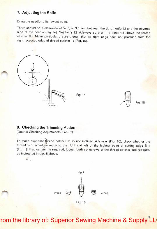
7. Adjusting the Knife
Bring the needle to its lowest point.
There should be a clearance of 764", or 3.5 mm. between the tip of knife 12 and the obverseside of the needle (Fig. 14). Set knife 12 sideways so that it is centered above the threadcatcher tip. Make particularly sure though that its right edge does not protrude from theright recessed edge of thread catcher 11 (Fig, 15).
Fig. 14
35 mmFig. 15
8. Checking the Trimming Action(Double-Checking Adjustments 5 and 7)
To make sure that aread catcher 11 is not inclined sideways (Fig, 16), check whether thethread is trimmed,9?>rrectly to the right and left of the highest point of cutting edge 8 1(Fig. 1). If adjustment is required, loosen both set screws of the thread catcher and readjust,as instructed in par. 5 above.
right
wrong wrong
Fig. 16
From the library of: Superior Sewing Machine & Supply LLC
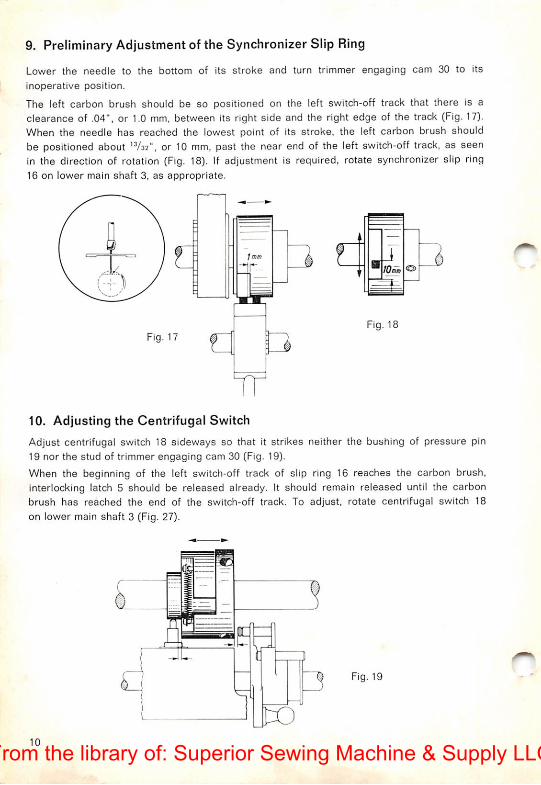
9. Preliminary Adjustment of the Synchronizer Slip Ring
Lower the needle to the bottom of its stroke and turn trimmer engaging cam 30 to itsinoperative position.
The left carbon brush should be so positioned on the left switch-off track that there is aclearance of .04", or 1.0 mm, between its right side and the right edge of the track (Fig. 17).When the needle has reached the lowest point of its stroke, the left carbon brush shouldbe positioned about ^^32", or 10 mm, past the near end of the left switch-off track, as seenIn the direction of rotation (Fig, 18). If adjustment is required, rotate synchronizer slip ring16 on lower main shaft 3, as appropriate.
Fig. 17
:T[_l^
Fig. 18
10. Adjusting the Centrifugal Switch
Adjust centrifugal switch 18 sideways so that it strikes neither the bushing of pressure pin19 nor the stud of trimmer engaging cam 30 (Fig. 19).
When the beginning of the left switch-off track of slip ring 16 reaches the carbon brush,interlocking latch 5 should be released already. It should remain released until the carbonbrush has reached the end of the switch-off track. To adjust, rotate centrifugal switch 18on lower main shaft 3 (Fig. 27).
Fig. 19
10From the library of: Superior Sewing Machine & Supply LLC

11. Timing the Needle Thread Tension Release
Attach feed dog, needle plate and presser foot, and lower the latter onto the needle plate.
The needle thread tension should be released when trimmer engaging shaft 4 has completedabout one half of its travel. Adjustment is made by loosening binding screw 22 and lengthening or shortening the connection (Fig. 20). When trimmer engaging shaft 4 is at its extremeleft-hand position, the needle thread tension must be operative.
Fig. 20
12. Checking the Operation of the Reverse Feed Mechanism(Pfaff machines 461, 463 and 465)
Set the machine for its longest stitch and reverse the direction of feed by depressing thereverse feed control. Turn trimmer engaging cam 30 downwards away from stop 28, thus
pushing the two-part connection together completely. As you do this, the end of the channeltrack of trimmer engaging cam 30 must not move beyond the center line of guide roller 31(Fig. 21). If adjustment is required, turn feed reversing crank 33 on the feed regulating shaft,as may be required.
11
From the library of: Superior Sewing Machine & Supply LLC

13. Adjusting the Motor Connection
To set pedals 24 and 26 in the most convenient position for operation, adjust the lengthof motor connection 25, as appropriate.
If it should become necessary later to adjust the position of one of the pedals or of themotor, follow the instructions given in par. 14 below.
14. Adjusting the Trimmer Connection
Bring the needle to its lowest point.
Push the top end of two-part connection 27 onto the ball stud of trimmer engaging cam 30.Rotate this cam until it contacts stop 28 and depress the rear ends of both pedals as far asthey will go. With the pedals in this position, the ball cup at the lower end of connection 27should be positioned about .04", or 1 mm, below the ball stud on the pedal (center-to-centerdistance, as illustrated in Fig. 22).
1mm
Fig. 23
15. Checking the Pedal Operation
Set the machine for its longest stitch and depress the tip of the right pedal 24. As you dothis, the reverse feed control must not make any perceptible motion.
Depress the rear end of the left pedal 26 until its stop engages the underside of the rightpedal. As you do this, roller lever 9 must not make any motion toward knife cam 2.
Both settings can be adjusted by the stop screw on the right pedal (Fig. 23).
12
From the library of: Superior Sewing Machine & Supply LLC
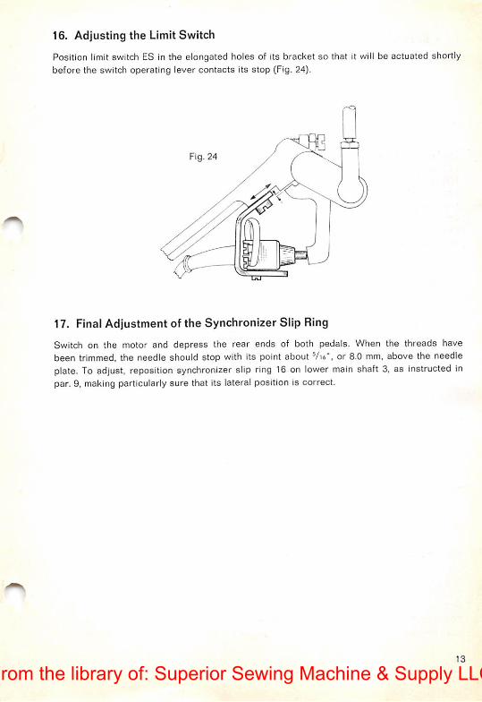
16. Adjusting the Limit Switch
Position limit switch ES in the elongated holes of its bracket so that it will be actuated shortlybefore the switch operating lever contacts Its stop (Fig. 24).
Fig. 24
LAJ~
17. Final Adjustment of the Synchronizer Slip Ring
Switch on the motor and depress the rear ends of both pedals. When the threads havebeen trimmed, the needle should stop with its point about Vu", or 8.0 mm, above the needleplate. To adjust, reposition synchronizer slip ring 16 on lower main shaft 3, as instructed inpar. 9, making particularly sure that Its lateral position is correct.
13
From the library of: Superior Sewing Machine & Supply LLC
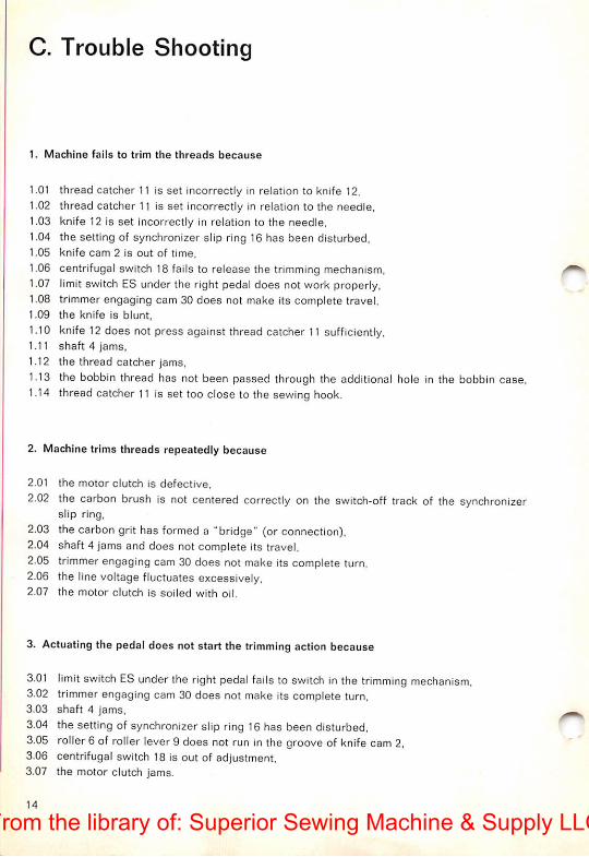
C. Trouble Shooting
1. Machine fails to trim the threads because
1.01 thread catcher 11 is set incorrectly in relation to knife 12,1.02 thread catcher 11 is set incorrectly in relation to the needle,
1.03 knife 12 Is set incorrectly in relation to the needle,1.04 the setting of synchronizer slip ring 16 has been disturbed,1.05 knife cam 2 is out of time,
1.06 centrifugal switch 18 fails to release the trimming mechanism,1.07 limit switch ES under the right pedal does not work properly,1.08 trimmer engaging cam 30 does not make its complete travel,1.09 the knife is blunt,
1.10 knife 12 does not press against thread catcher 11 sufficiently,1.11 shaft 4 jams,1.12 the thread catcher jams,1.13 the bobbin thread has not been passed through the additional hole in the bobbin case.1.14 thread catcher 11 is set too close to the sewing hook.
2. Machine trims threads repeatedly because
2.01 the motor clutch is defective,
2.02 the carbon brush is not centered correctly on the switch-off track of the synchronizerslip ring,
2.03 the carbon grit has formed a "bridge" (or connection),2.04 shaft 4 jams and does not complete its travel,2.05 trimmer engaging cam 30 does not make its complete turn,2.06 the linevoltage fluctuates excessively,2.07 the motor clutch is soiled with oil.
3. Actuating the pedal does not start the trimming action because
3.01 limit switch ES underthe right pedal fails to switch in the trimming mechanism,3.02 trimmer engaging cam 30 does not make its complete turn,3.03 shaft 4 jams,3.04 the setting of synchronizer slip ring 16 has been disturbed,3.05 roller6 of roller lever9 does not run in the groove of knife cam 2.3.06 centrifugal switch 18 is out of adjustment,3.07 the motor clutch jams.
14
From the library of: Superior Sewing Machine & Supply LLC

4. Needle thread end too short because
4.01 the upper tension is not open during the trimming action,4.02 the needle thread is considerably retarded as it enters the upper tension,4.03 the threads are trimmed before the take-up lever has reached the top of its stroke,4.04 thread catcher 11 is adjusted incorrectly so that all three threads are caught behind
heel 11.1 on the left-hand side of the thread catcher,
4.05 the extra spring in the upper tension is too strong.
5. Bobbin thread end too short because
5.01 the reduced speed of the machine is too high,5.02 the bobbin thread is not severed by the cutting edge provided for this purpose.
6. Needle thread end too long because
6.01 the extra spring in the upper tension is missing or too weak.
7. Needle thread end lies on material because
7.01 it was held down by the presser foot.
8. Thread kinks at beginning of seam because
8.01 the upper tension does not work properly,8.02 an excessive amount of thread was pulled through/the upper tension for the trimming
action.
9. Thread ends too long because
9.01 knife 12 has been adjusted improperly.
to. Work cannot be removed from under the presser foot because
10.01 the threads were not trimmed,
10.02 the needle thread end is jammed between sewing hook and thread catcher 1110.03 the needle is set too low.
11. Needle set too low after trimming because
11.01 synchronizer slip ring 16 is adjusted incorrectly,11.02 the voltage fluctuates,11.03 the motor clutch is soiled with oil.
12. Needle enters material after left pedal is released because
12.01 limit switch ES under the right pedal 24 is adjusted incorrectly.12.02 connection 27 between pedal 26 and the trimming mechanism is too long.
15
From the library of: Superior Sewing Machine & Supply LLC

D. Annex
1. Pedal Operation(on Pfaffmachines 461-900; 463-900; 465-900; and 467/469-900)
1. Depress tip of right pedal 24
2. Depress heel of right pedal 24
3. Depress tips of both pedals 24 and 26
4. Depress heels of both pedals 24 and 26
16
Fig. 25
Machine sews forward
Needle moves to iowest position
Machine sews backward
Needle moves to highest position
and both threads are trimmed.
From the library of: Superior Sewing Machine & Supply LLC

(on Pfaff machines 467-900 and 469-900)
1. Depress tip of right pedal 24
2. Depress heel of right pedal 24
3. Depress tips of both pedals 24 and 26
4. Depress heels of both pedals 24 and 26
Fig. 26
Machine sews forward
Needle moves to lowest position
Machine gathers
Needle moves to highest position andboth threads are trimmed.
2. Tilting the Machine Back
To tilt the machine back, remove connection 27 which connects pedal 26 to the trimmingmechanism. Never start the machine before connection 27 has been replaced because thereis a danger that the trimming action may have been triggered off and the trimmer may bedamaged by the high starting speed of the machine.
When the connection has been replaced, a stop on the left pedal automatically switchesoff the trimming mechanism at the beginning of the sewing action.
17
From the library of: Superior Sewing Machine & Supply LLC
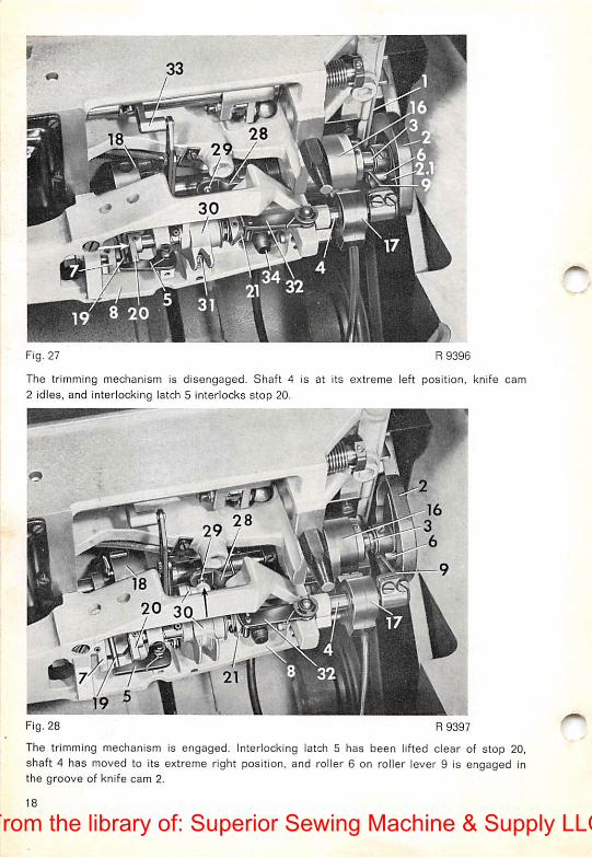
Fig. 27 R 9396
The trimming mechanism is disengaged. Shaft 4 is at its extreme left position, knife cam2 idles, and interlocking latch 5 interlocks stop 20.
20 3^
Fig. 28 R9397
The trimming mechanism is engaged. Interlocking latch 5 has been lifted clear of stop 20,shaft 4 has moved to its extreme right position, and roller 6 on roller lever 9 is engaged Inthe groove of knife cam 2.
18
From the library of: Superior Sewing Machine & Supply LLC
s
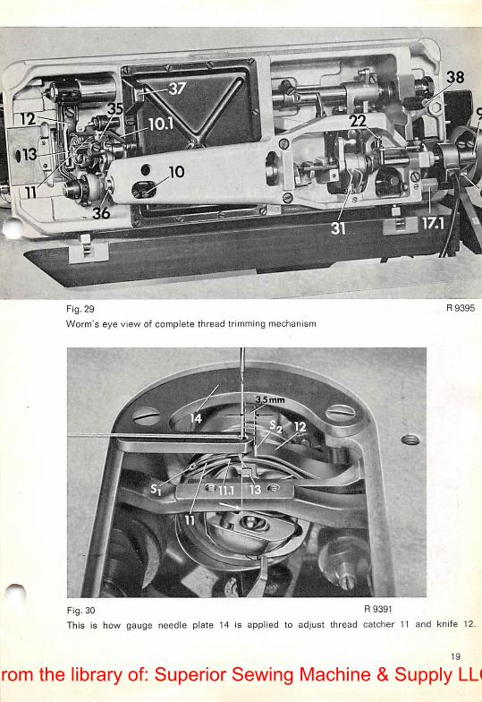
Fig. 29
Worm's eye view of complete thread trimming mechanism
5 mm
R9395
Fig.30 R 9391
This is how gauge needle plate 14 is applied to adjust thread catcher 11 and knife 12.
19
From the library of: Superior Sewing Machine & Supply LLC
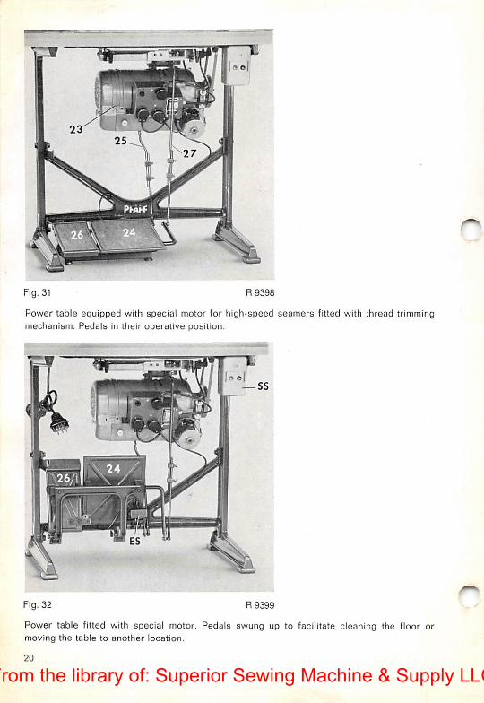
Fig. 31 R9398
Power table equipped with special motor for high-speed seamers fitted with thread trimmingmechanism. Pedals in their operative position.
Fig. 32 R9399
Power table fitted with special motor. Pedals swung up to facilitate cleaning the floor ormoving the table to another location.
20
From the library of: Superior Sewing Machine & Supply LLC
Contents
A. Operation and Maintenance
1. General
2. Operation3. Maintenance
B. Adjustment
1. Adjusting the Interlocking Latch2. Endwise Adjustment of Knife Cam3. Adjusting the Roller Lever4. Double-checking Adjustments 1—35. Adjusting the Thread Catcher6. Adjusting the Knife Cam7. Adjusting the Knife8. Checking the Trimming Action
9. Preliminary Adjustment of the Synchronizer Slip Ring .10. Adjusting the Centrifugal Switch11. Timing the Needle Thread Tension Release . . . .12. Checking the Operation of the Reverse Feed Mechanism .13. Adjusting the Motor Connection14. Adjusting the Trimmer Connection15. Checking the Pedal Operation16. Adjusting the Limit Switch17. Finai Adjustment of the Synchronizer Slip Ring
C. Trouble Shooting
1. Machine fails to trim the threads
2. Machine trims threads repeatedly
3. Actuating the pedal does no start the trimming action4. Needle thread end too short
5. Bobbin thread end too short
6. Needle thread end too long7. Needle thread end lies on material ....
8. Thread kinks at beginning of seam ....9. Thread ends too long
10. Work cannot be removed
11. Needle set too low after trimming12. Needle enters material after left pedal is released .
D. Annex
1. Pedal Operation .
2. Tilting the Machine Back .3. Thread Trimmer Illustrations
4
5
6
7
8
8
9
9
10
10
11
11
12
12
12
13
13
14
14
14
15
15
15
15
15
15
15
15
15
16
17
18—20
21
From the library of: Superior Sewing Machine & Supply LLC
From the library of: Superior Sewing Machine & Supply LLC

r<
From the library of: Superior Sewing Machine & Supply LLC

From the library of: Superior Sewing Machine & Supply LLC

-I '*. •
'_> • f
v:f-.r ••.
.1- .
V," I
Nr. 12310 engl. R 466
Z 2^ 7 5.J'
®
(PFAFF)
o
Printed in Germany
From the library of: Superior Sewing Machine & Supply LLC