Embed Size (px)
Citation preview
T.'
: 7AD...
AMPARC TR 78-41 !7
THIXOCASTING STEEL PARTS
September 1978
f by M. C. Flemings, John F. Boylan, Richard L. ByeMASSACHUSETTS INSTITUTE OF TECHNOLOGY )
Department of Materials Science and EngineeringCambridge, Massachusetts 02139
C= FINAL TECHNICAL REPORT: CONTRACT NUMBER DAAG-46-77-C-0033
Spo wored by; Amy Materisk 'r Mechanics fResearch CUrter
Effecdvo Date of Contract: 1 April 1.977
..... Contract Expiration Date: 30 Juas 1978
Amount of Contract- $196,05 D CContact Period Covert-d by Repoit: I Apni 1977 - 30 Jun~e 1978 . L 4- f
- ' j 197X ', .
Approved for public release; distribution unlimited. ,J..
Prepared tor-ARMY MATERIALS AND MEOHANI:CS RESEkstH CENTERWatertown,Lassachusetts 02t2 1 ,
"'7 -' _ I J & J " .

The views and conclusions contained In this document ,re those of theauthors and should, not be interpreted as necessarily representing theofficial policies, either expressed or implied, of the Defense AdvanccdResearch Projects Agency of I'e U.S. Government.
Mention of any trade names or manufacturers In this reportshall not be construed as advertising nor as an officialindortemont or approval of sueh. products or companies bythe United States Government
DI80-gSImION M'R1UCTtPJS . ,Ds-oy this resmwr whcn it IS r.- ' nr noeo..JDO not return it to ots-otiJrtator.

ACCESWI!N for
NTIS Wh'1e SOctia
IDC B; SectionTHIXOCASTING STEEL PARTS umWesouo -
JUSTIrICATi' •
BYFinal Technical Report DISTIAI.1",',
Contract No. DAAG46-77-C-003 ist.
September 1978
by
Merton C. Flemings, John F. Boylan, Richard L. Bye
MASSACHUSETTS INSTITUTE OF TECHNOLOGYDepartment of Materials Science and Engineering,
Cambridge, Massachusetts 02139
Sponsored by: Army Materials & Mechanics Research Center
Effective Date of Contract: 1 April 1977
Contract Expiration Date: 30 June 1978
Amount of Contract: $196,935
Contract Period Covered by Report: 1 April 1977 - 30 June 1978
I~~' I " , "
,• r t - * ,.! t ... . . ..''
UNC LASS IFIlEDSECURITY CLASSIFICATION OF THInS PAGE (If,.,n Date Entered) __________________
7. AEPT N
4. COTL LG OFtiCe) NAME AN AOORAELSl OVRE
Army ~ ~ ~ ~ ~ ~ ~ ia MaeilenpehnisRsac etrWRW e to Ma s c uTt 02 7 lMM Z ~ t
EjHIX:0C:ASTIG,,TEE jPART# 1Apr77 W1267
tS. OISTRIUTIORNAT N AME AND R DRSS1.PRGAMo0rl t)f .TS
Effachutiv Da stte of otrct: o~g 1M April 1977.184WConrate Exatiacuete: 0230ue17
Thixclassiting
T0. -DSTRACUT(ItON e- AT MT (of thi RepCor) i dntt ySoc ib
Thiroe ort decriese Thixri casing procmiessappidt
the DIeUTO cSTiTMN of tesalntre AII 4340k pats If0 shotse ofl semi-t
Spoli AIS: 430wrey catrinan industrnial disearcastintacintofinetige Dte ofeCnasilty of thepixoas prcesfo7tilotallyctel prthen Dtioasig prdue demnstat good
qualtYD wCih a radiographeitncsr exaintion shoin lwc porositylevesTherelgca eairofRecsAS 30iqualaieysmlrtthtootealosreisl
43IJN~ 473 elINFNV*ISLT UCASFE
<,iTf2h EURT CASFIAIO F unSPG Wmn ae nevg/
I
UNCASSIFIED" SECUPTY CLAt N $CATION OF TWI$ PiAC(ll Du. b&ea 0
" lock No. 20
ABSTRACT
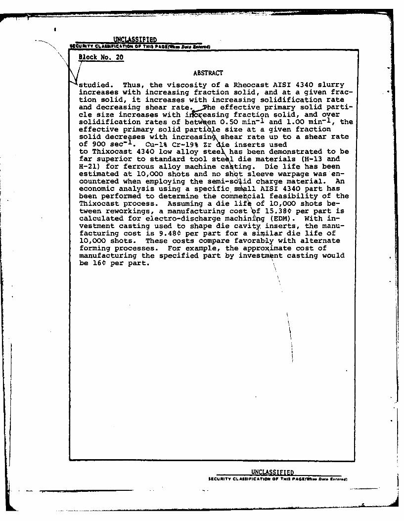
studied. Thus, the viscosity of a Rheocast AISI 4340 slurryincreases with increasing fraction solid, and at a given frac-tion solid, it increases with increasing solidification rateand decreasing shear rate. e effective primary solid parti-cle size increases with i easing fraction solid, and oversolidification rates of betw en 0.50 min-1 and 1.00 min-1 , theeffective primary solid parti e size at a given fractionsolid decreases with increasin shear rate up to a shear rateof 900 sec-1 . Cu-l% Cr-19% Zr -e inserts usedto Thixocast 4340 low alloy stee has been demonstrated to befar superior to standard tool ste 1 die materials (H-13 andH-21) for ferrous alloy machine ca ting. Die life has beenestimated at 10,000 shots and no shot sleeve warpage was en-countered when employing the semi-solid charge material. Aneconomic analysis using a specific snll AISI 4340 part hasbeen performed to determine the commetcial feasibility of theThixocast process. Assuming a die lif4 of 10,000 shots be-tween reworkings, a manufacturing cost f 15.380 per part iscalculated for electro-discharge machinipg (EDM). With in-vestment casting used to shape die cavity inserts, the manu-facturing cost is 9.480 per part for a siriilar die life of10,000 shots. These costs compare favorably with alternateforming processes. For example, the approximate cost ofmanufacturing the specified part by investment casting wouldbe 160 per part.
UNCLASSIFIEDSICUMITY CLASSIFICATION OF THIS PAG4(lfgen Dos Euteed)
iT
This report was supported and monitored
by the Army Materials and Mechanics Research Center
under Contract No. DAAG46-77-C-0033.

li
TABLE OF CONTENTS
SectionNumber Numer
Abstract 1
I Introduction 4
II Rheocasting 6A. System Design and Operation 6
1. The High Temperature ContinuousRheocaster 6
2. Operating Procedure 10
a. Continuous Production 10b. Static Tests 11
B. Determination of Parameters 121. Fraction of Solid 12
a. Continuous Production 12
b. Static Operation 13
2. Shear Rate 13
3. Solidification Rate 14
4. Particle Size and Entrapped Liquid 155. Viscosity 176. Composition 19
C. Results1. Microstructure and Composition of
Water-Quenched Rheocast AISI 4340 192. Rotor Drive Amperage Versus
Fraction of Solid 20a. Continuous Production 21b. Static Tests 22
3. Viscosity Versus Fraction of Solid 23

iii
Section PiiieNumber N75ber
4. Effective Particle Size 23
a. Effective Particle SizeVersus Fraction of Solid 24
b. Effective Particle SizeVersus Shear Rate 25
c. Effective Particle SizeVersus Solidification Rate 26
d. Effective Particle SizeVersus Viscosity 26
III Thixocasting 28
A. Systems Development 28
B. Pilot Plant Operation 36
C. Casting Properties 37
1. Microstructure and Compositionof Thixocast AISI 4340 38
2. Fraction of Solid 39
3. Porosity 394. Hardness 395. Determined Cooling Rate During
Solidification 40
D. Machine Component Wear 40
1. Plunger Tip 41
2. Shot Sleeve 42
3. Runner Pads 43
4. Die Cavity Inserts 43
IV Economic Analysis 46
A. Rheocasting 48
B. Thixocasting 53
V Discussion 60
VI Conclusions 63

iv
Section P
Number
Ref erence 65
Tables 68
Figures 78
Appendix A Al
Appendix B A6
ABSTRACT
This is the final report describing research
conducted at the Massachusetts Institute of Technology
on "Thixocasting of Steel Parts". It covers a one-
year contract period, beginning 1 April, 1977, and
represents a follow-up concluding study to the four-
year ARPA-sponsored research program conducted at
M.I.T. on "Machine Casting of Ferrous Alloys".
The Thixocasting process was applied to the die
casting of small, AISI 4340 parts. The process
comprised: (1) the continuous production of a semi-
solid metal slurry by vigorous agitation during
initial solidification, (2) complete solidification
of the slurry in ingot form, (3) reheating of the
ingot to the casting temperature within the liquid-
solid region, and (4) casting of the semi-solid ingot
in a conventional cold-chamber die casting machine (in
this case, employing copper dies (Cu-l% Cr-19% Zr)
operating at 500C.).
Approximately 2000 pounds of 10-ounce AISI 4340
ingots were produced in a high temperature continuous
Rheocaster. Design, control method, and operation of
2
the Rheocaster is described in detail. The rheological
behavior of Rheocast AISI 4340 is qualitatively similar
to that of other alloys previously studied (e.g., tin-
lead, copper, aluminum, and other ferrous alloys). The
viscosity of a Rheocast AISI 4340 slurry increases with
increasing fraction solid and decreasing shear rate.
2,200 shots of semi-solid AISI 4340 were cast in
an industrial die casting machine to investigate the
feasibility of the Thixocast process for low alloy steel.
The operating procedure and system components are des-
cribed in detail. Thixocastings produced demonstrate
good quality. Primary solid particles were uniformly
distribUted in a rapidly solidified matrix. The
average volume fraction of primary solid particles in
the charge material was 0.41. Thixocast 4340 low alloy
steel experienced very rapid cooling rates during solidi-
fication ( >1040C/sec) when machine cast in Cu-Cr-Zr dies
operating at 500C. Radiographic examination of the
Thixocast parts showed low porosity levels.
The Cu-Cr-Zr alloy has been demonstrated to be far
superior to standard tool steel die materials (H-13 and
H-21) for ferrous alloy machine casting. Based on the
condition of the die cavity insert set after 2,200 shots,
die life has been estimated at 10,000 shots. No shot
sleeve warpage was encountered when employing a semi-
solid charge material.
3
An economic analysis using a specific small AISI
4340 part has been performed to determine the commercial
feasibility of the Thixocast process. Using electro-
discharge machining (EDM) for die cavity preparation
and assuming a die life of 10,000 shots between reworkings,
a manufacturing cost of 15.380 per part is calculated.
Significant economic advantage can be realized by the use
of investment casting to shape die cavity inserts, pro-
vided a similar die life of 10,000 shots is realized.
A manufacturing cost of 9.48¢ per part is calculated.
These costs compared favorably with alternate
forming processes. For example, the approximate cost
of manufacturing the specified part by investment casting
would be 16€ per part.
4
I. INTRODUCTION
In January, 1973, a joint university-industry research
program was undertaken to develop an economical method of
machine casting ferrous alloys. The portion of this program
conducted at<M.I.T. dealt primarily with Rheocast and Thixo-
cast development. In Rheocasting, a semi-solid slurry of
a metal alloy is produced by vigorous agitation of a solidi-
fying melt. This highly fluid slurry, having a consistencyof a heavy machine oil, is then cast directly to shape. In
Thixocasting, shown schematically in Figure 1, fully solidi-
fied ingots of Rheocast metal are reheated to the liquid-
solid region and cast. Due to the thixotropic nature of
Rheocast slurries, the reheated charges retain their shape
and can be handled as soft solids during transfer to the die
casting machine. The high shear rates experienced by the
metal during casting reduces the slurry viscosity to a level
at which it flows smoothly into the die cavity.
Work at M.I.T. performed under the "Machine Casting
of Ferrous Alloys" program has demonstrated the technical
feasibility of the Thixocast process for machine casting
small parts. Development efforts have been conducted with
tin-lead, copper, aluminum, and several stainless steel
alloys( - 6). Die life studies performed under that program
with various die materials have shown that the Thixocast
process utilizing surface quenched copper base Elbrodur RS
dies extends die life beyond that possible with liquid
ferrous alloys die cast with conventional mold materials.
Figure 2, taken from this earlier work(61, and showing the
500th castings produced in H-13 and H-21 tool die steels,
___ __ _ __ _.

5
Cu-0.8% Cr, and Elbrodur RS dies, demonstrates that copper
dies have a longer life than do conventional steel dies.
During this contract year, the basic Thixocasting
system was adapted for pilot plant production of low alloy
steel components to demonstrate the technical and economic
feasibility of producing large quantities of these parts
by the Thixocasting process. The specific objectives of
the work presented herein are:
1. to adapt the Rheocaster and Thixocasting system for use
with AISI 4340 low alloy steel,
2. to study the relationships between process variables
and the rheological behavior of AISI 4340 slurries,
3. to investigate the effects of Thixocasting AISI 4340 on
machine component lives, especially die life,
4. to evaluate the quality of AISI 4340 parts produced by
the Thixocast process, and
5. to evaluate the economic feasibility of the Thixocast
process for large volume production of low alloy steel
parts.
d"~~ ~ ~ ~~ ~~~~~~~~~~~~~~ . ... .... . .... . .. . ... .Il l .... . Ill
... . .. .. .. ... .. ...... .
6
II. RHEOCASTING
The major aim of this program has been to determine the
feasibility of producing ferrous parts by the Thixocastingprocess. In line with this aim, approximately 2000 pounds
of Rheocast AISI 4340 have been produced for subsequent use
in the Thixocast pilot plant studies.
Using the standard Rheocaster, data were collected
during production runs and separate tests conducted to
determine the reliability of the method used to control the
Rheocaster and to examine the relationships between the
physical characteristics of the 4340 slurries and the processconditions under which they were made. These relationships
were then compared to those found in earlier work (7 - 1 0 ) using
tin-lead alloys.
A. System Design and Operation
1. The High Temperature Continuous Rheocaster
A picture of the high temperature continuous Rheo-
caster and its support equipment is shown in Figure 3. A
schematic drawing of the Rheocaster is shown in Figure 4.
Only minor modifications in the continuous Rheocasting
system developed at M.I.T. were necessary to adapt it for
Rheocast AISI 4340 production. Improved shielding of themelt and the exit area has been accomplished by the increased
use of argon-4% hydrogen. This has resulted in cleaner
ingots that are free of blow holes and has reduced slag
attack on furnace parts.
7
The ingot-making procedure has also been changed
for Rheocast AISI 4340 production. Exiting Rheocast metal
is now collected in Fiberfrax lined molds which are handled
individually on a rotating turntable rather than being
packed into canisters as were the stainless steel molds
employed previously. The ingots are 1-1/4 in. diameter
and 1-3/4 in. long and weigh approximately 10 ounces. After
the molds have filled, the top of the ingot is tamped so
that both ends of the ingot are flat. These ingots can be
Thixocast directly, eliminating the time and material waste
involved in cutting larger ingots into separate charges.
The graphite molds last longer than do the stainless steel
molds used previously and are more easily prepared for re-
use. In addition, these shot-sized ingots have been foundto reheat more uniformly than sectioned ingots.
During continuous production of Rheocast AISI 4340,
9/16" diameter rod stock is continuously melted in the upper
chamber of the Rheocaster. At the same time, metal flowing
into the mixing chamber is cooled and vigorously agitated
by the turning rotor to produce the characteristic Rheocast
structure. The semi-solid slurry is extracted from the
bottom of the mixing chamber at a controlled volume fraction
of solid.
The main body of the Rheocaster is a slip cast,1/2" thick crucible made from Vesuvius #235 (58% A1203 ,
26% C, 12% Si0 2). The upper chamber, which is the melting
and holding chamber, is 5-3/8" in diameter and 7-1/2" high
and holds approximately 40 pounds of molten steel. The top
chamber is inductively heated by a 30 KW, 4.2 KHz Inducto-
therm motor generator unit. The melt is insulated and
. d

8
protected from the atmosphere by a layer of fire-brick and
two layers of Fiberfrax blanket. Argon-4% hydrogen is
introduced to the holding chamber through a stainless steel
tube to further protect the melt. The gas flow is regulated
so that a flame burns at the openings in the Fiberfrax
cover (around the rotor and the hole through which the feed
stock is introduced), indicating that oxygen has been ex-
cluded from the melt. The melt temperature is monitored by
a Pt-Pt 10% Rh thermocouple located in an alumina sheath
cemented to the crucible wall.
The mixing chamber consists of a 6" long alumina
combustion tube (1-1/4" ID x 1-1/2" OD,with a 1/4" diameter
exit hole) cemented inside the Vesuvius crucible. Aninduction coil, powered by a 20 KW, 10 KHz Radio Frequency
Company solid state inverter, surrounds the mixing chamber.With the power turned down, this coil acts as a cooling
coil for the mixing chamber. A recrystallized alumina
sleeve and 100 mesh alumina powder separate the coil from
the crucible.
In the lower chamber of the Rheocaster, the exitchamber, the nozzle end of the alumina combustion tube is
supported by a specially machined graphite piece and a
ceramic disk. Argon-4% hydrogen flows through the gap
between two concentric alumina tubes cemented inside thegraphite piece and into the exit chamber to shield the
exiting Rheocast metal and prevent slagging up of the exit
port. A quartz tube is used to extend the gas shield to
the top of the ingot molds. The exit chamber is heated toprevent slurry from freezing in the exit port by an induc-
tion coil powered by a 10 KW, 190 to 610 KHz Lepel induction
9
unit. Temperature at the exit port is monitored by a
Pt-Pt 10% Rh thermocouple cemented to the outside of the
crucible wall.
The mixing rotor is an 18-3/4" long hollow alumina
tube with an outside diameter of 1-1/8". The lower six
inches of the rotor has a square cross section (1-1/8"
from corner to corner) to promote agitation and avoid
flow instabilities in the mixing chamber. The rotor is
driven by a 3/4 h.p. direct current motor capable of turn-
ing the rotor at speeds of between 0 and 1200 RPM. Therotation speed is controlled by a Minarik Model MR9O
constant speed controller and measured with a tachometer
placed on top of the rotor assembly. An ammeter is placed
in line with the motor to measure the amperage required to
drive the rotor at a given speed. The rotor assembly isdesigned to allow the rotor to be raised or lowered to
control the flow rate of the exiting Rheocast slurry. The
rotor can be seated on the bottom of the mixing chamber
to completely stop flow.
Three Pt-Pt 10% Rh thermocouples are placed inside
the rotor. They monitor the temperature at the bottom andmiddle of the mixing chamber and in the upper reservoir.
A set of rotary contacts has been designed to permit con-
tinuous monitoring of the EMF from these rotating thermo-
couples. The thermocouples are attached to a series ofcopper slip rings located at the top of the rotor assembly.
Electrical contact is made with a set of spring loaded
carbon brushes. The output of all thermocouples in the
Rheocaster is displayed on a Hewlett-Packard 7100 BM two-
channel chart recorder and a Keithley 190 digital voltmeter.
10
2. Operating Procedure
a. Continuous Production
At the start of a Rheocast production run the
rotor is positioned in the mixing chamber with a rotor-exit
separation of about 1/8" to allow for thermal expansion.
Approximately 20 .pounds of feed metal is placed in the top
chamber. Argon-4% hydrogen flow is turned on to both thetop and exit chambers. Power to all three induction coils
is then turned on and adjusted so that a relatively level
temperature profile, as indicated by the thermocouples
located at the exit, in the mixing chamber, and in the top
reservoir, is maintained. Thermal shock is thereby mini-
mized when the metal in the top reservoir melts.
After the initial charge has melted, the rotor is
seated at the exit port with the minimum pressure required
to prevent metal flow. The power supplies are adjusted tostabilize the melt temperature with a superheat of about
400C. The rotor is then rotated slowly while additional
metal is added to fill the upper chamber.
After the upper chamber is full, the rotation
speed of the rotor is adjusted to the desired level and
the amperage required to turn the rotor in the liquid metal
is recorded as a base level amperage. Power to the middle
coil is reduced so that enough heat is extracted from the
metal in the mixing chamber to produce the desired solidi-
fication rate.
From this point on, the Rheocaster is controlled
exclusively by monitoring the amperage required to drive
the rotor at constant speed. As the fraction of solid of
the Rheocast slurry increases, the viscosity increases,
and the amperage needed to drive the rotor increases. When
the desired amount of amperage increase above the base level
is reached, the rotor is raised and the metal flow rate is
adjusted to stabilize the amperage reading.
Exiting Rheocast metal is teemed into graphite moldslined with a 1/16" layer of Fiberfrax paper. Each ingot
weighs approximately 10 ounces. The fill time and amperage
reading during that time are recorded for each ingot. The
ingots are subsequently weighed and the flow rate for eachingot is calculated from the fill time and the weight. Water-
quenched samples of exiting Rheocast metal are collected
periodically for subsequent metallographic examination.
The Rheocaster is capable of producing approximately
250 pounds of 50% solid 4340 slurry per hour but the melting
rate is limited to about 60 pounds per hour by the size of
the available power supply. During production, the metal
flow rate is held to between 80 and 100 pounds per hour.At these rates, production can operate on a semi-continuous
basis while still allowing for good ingot fill-out.
Furnace life is currently limited to about 15 hours.Failures are not catastrophic and wear of the furnace parts
is not a factor in furnace life. Furnaces are generally
rejected because of a slight shift of the exit area with
respect to the rotor. This shift eventually results insevere rotor vibration and loss of flow rate control. A
minor design change to hold the crucible more rigidly would
significantly extend furnace life.
b. Static Tests
Static, viscometer-like tests were conducted in the
12
Rheocaster immediately after continuous production runs
were completed. The metal in the mixing chamber was heated
until it was completely liquid. The rotor speed was thenadjusted to the desired level and the power to the middle
coil was turned down. The rotor was seated at the exit
port so that no metal flow could occur. As the metalsolidified, amperage readings were recorded at the appro-
priate points on the chart recorder trace of the middle
rotor thermocouple output. Amperage and temperature were
continuously monitored until the slurry fraction of solidbecame so high that the motor shut off and the rotor seized.
The mixing chamber was then reheated to above the alloyliquidus for another trial. Experiments were run at several
rotation speeds and solidification rates.
Cooling and heating curves were also generated withoutrotor rotation to determine the freezing range of 4340.
The liquidus and solidus breaks in the chart recorder trace
of the middle rotor thermocouple were noted and found to be
consistent for several cooling and heating cycles. Thefreezing range of 4340 was found to be 73*C. The liquidusbreak occurred at 14796C.
B. Determination of Parameters
The three important process variables in Rheocasting
are fraction of solid, shear rate, and solidification rate
or cooling rate. In this study, the effects of these
variables on the primary particle size and the slurry were
studied.
1. Fraction of Solid
a. Continuous Production

13
Fractions of solid from the continuous production
runs were determined metallographically from the water-
quenched samples taken during the runs. The samples were
mounted and then polished in successive steps on wet, rota-ting silicon carbide papers of 30, 120, 240, 360, and 600
grit. Polishing was completed using 0.3 micron alumina
particles suspended in water on a rotating cloth wheel.The samples were etched for approximately 1-1/2 minutes
in a room temperature saturated solution of picric acidin water. The volume fraction of primary solid particles
was determined using a standard two-dimensional systematic
point counting procedure.(11)
b. Static Operation
Volume fraction of solid from the static tests
was determined from the cooling curves. The thermocouple
trace from each of the trials was extrapolated to theexperimentally determined solidus temperature. It wasassumed that the volume fraction of solid was a linear
function of solidification time between the liquidus and
the solidus.
2. Shear Rate
The shear rate in the mixing chamber is a function
of the rotor geometry, the clearance between the rotor andthe mixing chamber walls and the rotation speed.
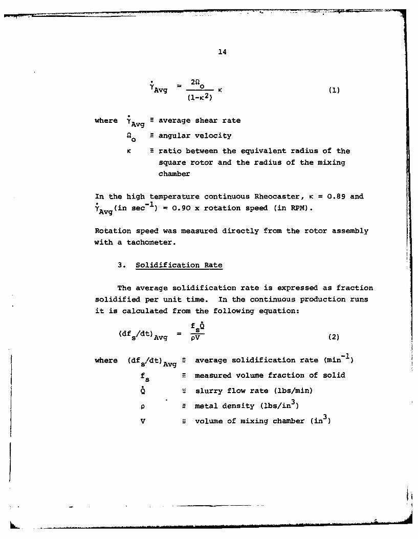
The average shear rate in the annulus of the mixing
chamber can be calculated from the following equation(12)
(ignoring axial flow of material):
14
TAvg - (1)(1-ic2 )
where A average shear rateAvgQ 0 E angular velocity
K ratio between the equivalent radius of the
square rotor and the radius of the mixing
chamber
In the high temperature continuous Rheocaster, K = 0.89 and
Avg (in sec- I) = 0.90 x rotation speed (in RPM).
Rotation speed was measured directly from the rotor assembly
with a tachometer.
3. Solidification Rate
The average solidification rate is expressed as fraction
solidified per unit time. In the continuous production runs
it is calculated from the following equation:
(df /dt) fs
s Avg - PV (2)
average solidification rate (min1 )
fs S measured volume fraction of solid
Q slurry flow rate (lbs/min)
p = metal density (lbs/in3
V volume of mixing chamber (in )

15
In the high temperature continuous Rheocaster:
-1-l fsQ(lbs min-(df /dt) (min- s (3)s Avg 0.82 (ibs)
In the static, viscometer-like tests, the averagesolidification rates were calculated by dividing the cal-
culated volume fraction of solid at the time the trial wasstopped by the time it took to cool to that point from the
liquidus.
Average cooling rates can be calculated by multiplying
the average solidification rates by the freezing range ofthe alloy. In this work, reference is made to average solidi-
fication rates rather than average cooling rates. Solidifi-
cation rate is the more meaningful concept when only partialsolidification is occurring. Cooling rate within the
liquid-solid region can vary more than solidification rate
in a system in which heat is extracted at a constant rate.
4. Particle Size and Entrapped Liquid
The water-quenched samples from the continuous produc-
tion runs were examined further to determine an effective
radius is the radius of uniformly sized spherical particleshaving the same surface to volume ratio as the primary solid
particles in the Rheocast 4340.
Areas near the edges of the water-quenched samples were
chosen for examination. In these areas, the quench rate was
higher and individual particles are more distinct. Thefraction of solid of these areas is generally lower than theoverall fraction of solid, but this was corrected as
described below.
16
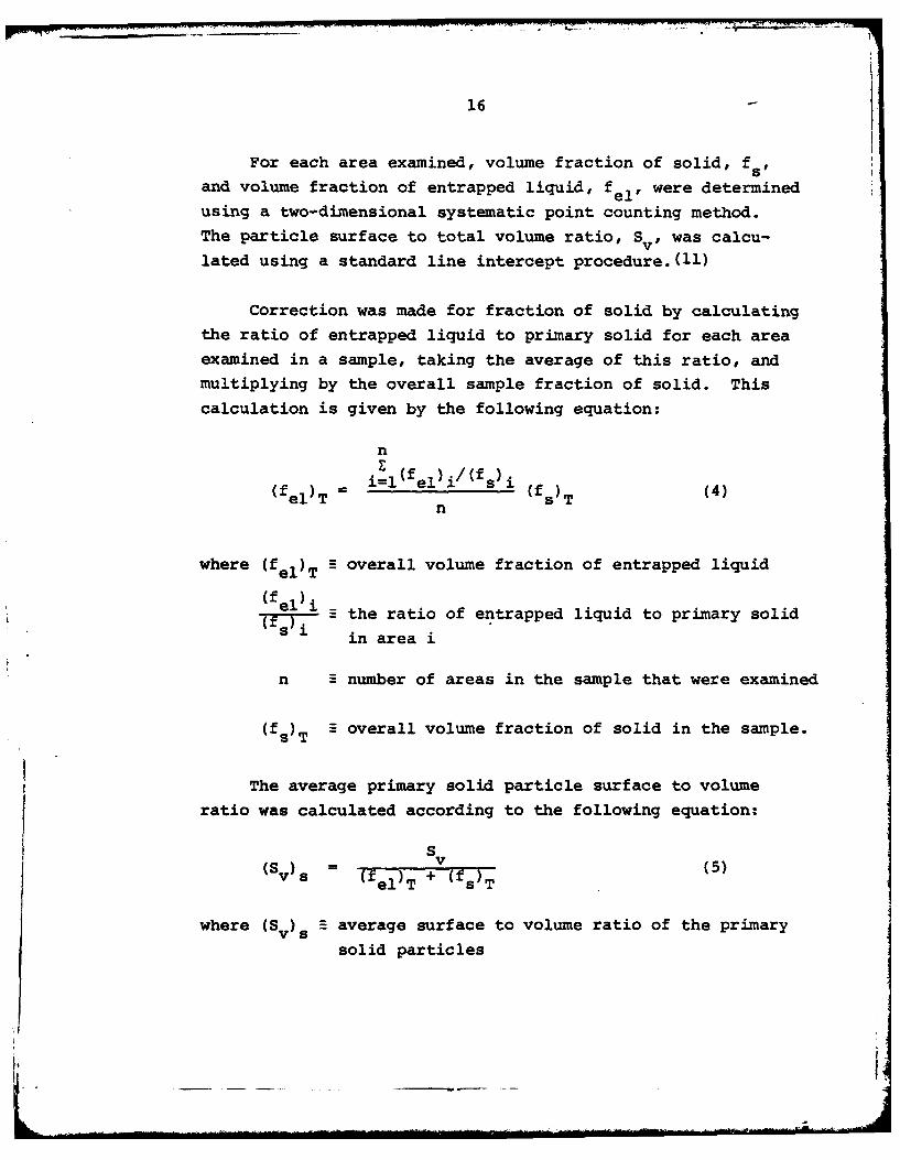
For each area examined, volume fraction of solid, fand volume fraction of entrapped liquid, fel' were determined
using a two-dimensional systematic point counting method.
The particle surface to total volume ratio, Sv , was calcu-
lated using a standard line intercept procedure. (11)
Correction was made for fraction of solid by calculating
the ratio of entrapped liquid to primary solid for each areaexamined in a sample, taking the average of this ratio, and
multiplying by the overall sample fraction of solid. This
calculation is given by the following equation:
nE
(fel) T -i=l el~i/fsi (f )T (4)
n
where (fel)T overall volume fraction of entrapped liquid
(f el) iTe - the ratio of entrapped liquid to primary solid
in area i
n number of areas in the sample that were examined
(fs)T S overall volume fraction of solid in the sample.
The average primary solid particle surface to volumeratio was calculated according to the following equation:
S(Sv) s = (fel)T + v(fs)T5
where (Sv)s B average surface to volume ratio of the primary
solid particles
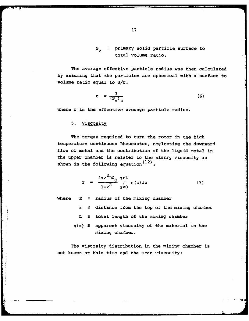
17
Sv -primary solid particle surface to
total volume ratio.
The average effective particle radius was then calculated
by assuming that the particles are spherical with a surface tovolume ratio equal to 3/r:
3 (6)v s
where r is the effective average particle radius.
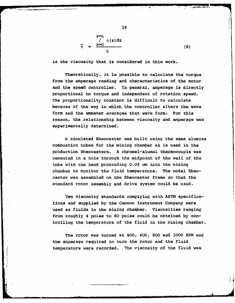
5. Viscosity
The torque required to turn the rotor in the high
temperature continuous Rheocaster, neglecting the downwardflow of metal and the contribution of the liquid metal inthe upper chamber is related to the slurry viscosity as
(12).shown in the following equation
4inc2R0 z-LT = f n(z)dz (7)
where R E radius of the mixing chamber
z distance from the top of the mixing chamber
L total length of the mixing chamber
n(z) apparent viscosity of the material in themixing chamber.
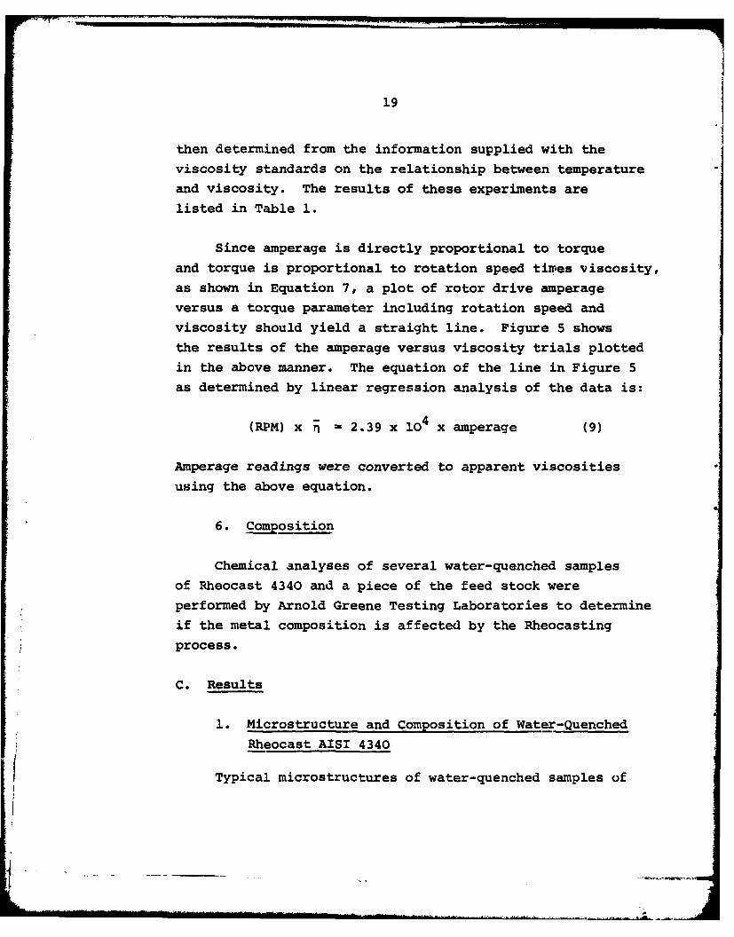
The viscosity distribution in the mixing chamber isnot known at this time and the mean viscosity:
18
z=Lf n(z)dz
= z (8)
L
is the viscosity that is considered in this work.
Theoretically, it is possible to calculate the torque
from the amperage reading and characteristics of the motor
and the speed controller. In general, amperage is directly
proportional to torque and independent of rotation speed.
The proportionality constant is difficult to calculate
because of the way in which the controller alters the wave
form and the ammeter averages that wave form. For this
reason, the relationship between viscosity and amperage was
experimentally determined.
A simulated Rheocaster was built using the same alumina
combustion tubes for the mixing chamber as is used in the
production Rheocasters. A chromel-alumel thermocouple was
cemented in a hole through the midpoint of the wall of the
tube with the bead protruding 0.05 cm into the mixing
chamber to monitor the fluid temperature. The model Rheo-caster was assembled on the Rheocaster frame so that the
standard rotor assembly and drive system could be used.
Two viscosity standards complying with ASTM specifica-
tions and supplied by the Cannon Instrument Company were
used as fluids in the mixing chamber. Viscosities rangingfrom roughly 4 poise to 80 poise could be obtained by con-
trolling the temperature of the fluid in the mixing chamber.
The rotor was turned at 400, 600, 800 and 1000 RPM and
the amperage required to turn the rotor and the fluid
temperature were recorded. The viscosity of the fluid was
19
then determined from the information supplied with the
viscosity standards on the relationship between temperature
and viscosity. The results of these experiments are
listed in Table 1.
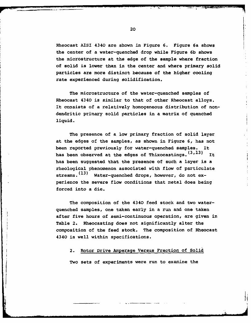
Since amperage is directly proportional to torque
and torque is proportional to rotation speed times viscosity,
as shown in Equation 7, a plot of rotor drive amperage
versus a torque parameter including rotation speed andviscosity should yield a straight line. Figure 5 shows
the results of the amperage versus viscosity trials plotted
in the above manner. The equation of the line in Figure 5
as determined by linear regression analysis of the data is:
(RPM) x r = 2.39 x 10⁴ x amperage (9)
Amperage readings were converted to apparent viscosities
using the above equation.
6. Composition
Chemical analyses of several water-quenched samples
of Rheocast 4340 and a piece of the feed stock were
performed by Arnold Greene Testing Laboratories to determine
if the metal composition is affected by the Rheocasting
process.
C. Results
1. Microstructure and Composition of Water-Quenched
Rheocast AISI 4340
Typical microstructures of water-quenched samples of
20
Rheocast AISI 4340 are shown in Figure 6. Figure 6a shows
the center of a water-quenched drop while Figure 6b shows
the microstructure at the edge of the sample where fraction
of solid is lower than in the center and where primary solid
particles are more distinct because of the higher cooling
rate experienced during solidification.
The microstructure of the water-quenched samples of
Rheocast 4340 is similar to that of other Rheocast alloys.
It consists of a relatively homogeneous distribution of non-
dendritic primary solid particles in a matrix of quenched
liquid.
The presence of a low primary fraction of solid layer
at the edges of the samples, as shown in Figure 6, has not
been reported previously for water-quenched samples. It
has been observed at the edges of Thixocastings. (3 '13) It
has been suggested that the presence of such a layer is a
rheological phenomenon associated with flow of particulate
streams. (13) Water-quenched drops, however, do not ex-
perience the severe flow conditions that metal does being
forced into a die.
The composition of the 4340 feed stock and two water-
quenched samples, one taken early in a run and one taken
after five hours of semi-continuous operation, are given in
Table 2. Rheocasting does not significantly alter the
composition of the feed stock. The composition of Rheocast
4340 is well within specifications.
2. Rotor Drive Amperage Versus Fraction of Solid
Two sets of experiments were run to examine the
21
relationship between the amperage required for the motor
to drive the rotor at a given speed and the fraction of
solid of the Rheocast 4340 produced. The experimental
procedures and the method of determining fraction of solid
for the continuous production runs and the static tests
were described in the previous section.
a. Continuous Production
There is a close correlation between the volume
fraction of primary solid in 4340 slurry exiting from the
high temperature Rheocaster and the amperage drawn by the
motor to turn the rotor at a given speed. The shape of the
curves in Figures 7 and 8 is as expected, based on previous
work with Sn-15% Pb slurries. (7-10) The fact that curves
of the type shown in Figures 7 and 8 can be generated from
continuous production runs indicates that the method used
to operate the high temperature continuous Rheocaster does
allow the output to be reasonably and reliably controlled.
In general, there is little increase in rotor drive
amperage until the metal at the mixing chamber exit is
roughly 25% solid. At fraction of solid above 0.25, the
amperage rises rapidly with increasing fraction of solid.
The rate at which the amperage increases with fraction of
solid is higher in slurries produced with low rotation speeds
than in those produced with higher rotation speeds.
The points plotted in Figure 7 represent data
collected from runs made in four separate Rheocasters with
average solidification rates of between 0.66 min1 and
0.95 min- and a rotation speed of 800 RPM. Rotor drive
22
amps increase from 0 to 1.5 as fraction of solid increases
from 0 to roughly 0.55 in Rheocast 4340 slurries produced
under these conditions. There appears to be no significant
difference between the results of runs made in different
furnaces.
Figure 8 shows the data points collected from runs
made in two separate furnaces with a rotation speed of 600
RPM and average solidification rates of 0.57 min- and 0.66
min-1 . Again, there are no significant differences attri-
butable to the use of the different furnaces. Rotor drive
amps increase from 0 to 1.6 amps as fraction of solid in-
creases from 0 to roughly 0.45.
b. Static Tests
The relationship between rotor drive amperage and
slurry fraction of solid can also be determined from static,
viscometer-like tests. The results of these tests are
similar to those obtained from continuout production runs.
Amperage increases with increasing fraction of solid with
an increasing rate of rise at higher fractions of solid.
Amperage increases faster at low shear rates or high solidi-
fication rates than at high shear rates or low solidification
rates. Figure 9 shows the results from static tests made at
*600 RPM with average solidification rates of 0.95 and 0.59
min "I and at 800 RPM with solidification rates of 0.76 and
0.38 min. Figures 10 and 11 show that the results of
* static tests and continuous production runs with equivalent
rotation speeds and solidification rates are in very good
agreement. The implication of this is that the relatively
simple static tests can be used to generate operating curves
for continuous Rheocast 4340 production.
23
3. Viscosity Versus Fraction of Solid
Rotor drive amperages from the continuous production
runs and the static tests were converted to viscositiesusing the procedures described in Section B-5. The results
are shown in Figures 12 and 13.
The relationship between viscosity and fraction of
solid of Rheocast AISI 4340 is qualitatively similar to
that in Sn-15% Pb slurries. (7-10) In both alloys, viscosityincreases at an increasing rate with increasing fraction of
solid. For a given fraction of solid and solidification
rate, a high shear rate produces a lower viscosity slurry
than does a low shear rate. For example, a 4340 slurrythat is 45% solid has an apparent viscosity of roughly 15
poise with a shear rate of 900 sec-1 , 25 poise with a shear
rate of 720 sec-1 , 60 poise with a shear rate of 540 sec-1,and 100 poise with a shear rate of 360 sec-1 when solidified
at rates of between 0.43 and 0.82 min-1 . A high solidi-
fication rate produces a higher viscosity slurry of a given
fraction of solid than does a low solidification rate with
the same shear rate.
Viscosities of Rheocast 4340 slurries are of the same
order of magnitude as those of Sn-15% Pb slurries at the
same fractions of solid 7 -10) However, quantitative com-
parisons between the two were difficult to make because of
the different method in which the viscosities of the twoalloys were measured.
4. Effective Particle Size
The effect of slurry fraction of solid and shear rate
24
cnthe average primary solid particle size and the effect
of particle size on slurry viscosity for Rheocast 4340
slurries have been found to be similar to those reported
for Sn-15% Pb slurries (9'10 ) and 304 stainless steel
slurries14)
Average particle sizes in Rheocast 4340 slurries
produced within the range of solidification rates and shearrates employed in this work are roughly the same as those
calculated from data on 304 stainless steel slurries pro-
duced under similar operating conditions. 14) Particle sizes
in the 4340 slurries produced in this work are approximately
three times those reported for Sn-15% Pb slurries produced
at about the same solidification rate. (9,10,15)
a. Effective Particle Size Versus Fraction of Solid
Figure 14 shows the relationship between effective
primary particle size and fraction of solid of Rheocast 4340.
Each point represents an average of several samples at the
appropriate shear rate and fraction of solid. In general,
particle size appears to remain essentially constant up to
fractions of solid of 0.25 after which it increases with
increasing fraction of solid. In Rheocast slurries produced
with an average shear rate of 720 sec-1 and solidification
rates of between 0.66 min - and 0.95 min, the effective
particle size increases from 110 microns at 25% solid to
16Q microns at 53% solid. Figure 15 is a series of micro-
graphs which illustrate the increase in effective particle
size with increasing fraction of solid.
The finding that primary solid particle size
25
increases with increasing fraction of solid in Rheocast4340 agrees with the results of previous studies of
Rheocast Sn-15% Pb(3'9'1 0 ) and Rheocast AISI 304 stainless
steel. (14) Growth of primary solid particles can occur bya coarsening mechanism similar to that proposed for coarsen-
ing of dendritic structures, a process similar to the
Ostwald ripening mechanism, and the coalescence and agglo-
meration of particles. Because these processes are time
dependent, and because high fraction of solid slurries havea longer residence time in the mixing chamber than do low
fraction of solid slurries, average particle sizes are
larger in high fraction of solid slurries than in low
fraction of solid slurries.
b. Effective Particle Size Versus Shear Rate
The effect of shear rate on effective particle
size is shown in Figure 16. At fractions of solid above
about 0.25, an increase in shear rate results in a decrease
in effective particle radius. The effect of shear rate onparticle size is greater at high than at low fractions of
solid. In 46% solid slurries produced at 400 RPM, the
effective particle radius is roughly 185 microns. In 46%
solid slurries produced at 800 RPM, the effective particlesize is 135 microns. The microstructures shown in Figure
17 illustrate the effect of shear rate on effective particlesize. Previous work has shown that this same relationship
between shear rate and particle size exists for shear rates
between 230 and 750 sec- I in Rheocast Sn-15% Pb slurries
solidified at a rate of 0.01 min-. (7,10) There are con-
flicting reports (9'15'16'17 ) on the effect of shear rateon particle size in Rheocast Sn-15% Pb solidified at rates
__ _ _ _ _ _ ___ _ _ _ _ _ __ _ _ _ _ _ i

26
between 0.01 min-1 and 2.0 min-1 , but no effect has been-1observed with solidification rates higher than 2.0 min(9,16,17)
The relationship between shear rate and particle
size is probably a result of the effect of shear rate on
particle coalescence. Joly (9) has argued that high shear
rates tend to prevent the formation of welds between
particles. If this is true, at high shear rate, there
should be very little particle agglomeration and, there-
fore, very little shear rate effect on particle size.
Figure 16 indicates that the effect of shear rate on
particle size in Rheocast 4340 diminishes at shear rates
above 900 sec-l1
c. Effective Particle Size Versus Solidification
Rate
No effect of solidification rate on primary solid
particle size in Rheocast 4340 was observed within the
range of solidification rates employed in this work. The
scatter of particle sizes found in this work is about the
same size as any expected variation due to a cooling rate
effect. The average primary solid particle diameters in
Rheocast 4340 are approximately the same size as primary
dendrite arm spacings in 4340 solidified dendritically at
about the same rate. (18) A correspondence between primary
solid particle size and primary dendrite arm spacing has
been reported for Sn-15% Pb and for cobalt based X-40superalloy.
(15)
d. Effective Particle Size Versus Viscosity
In Rheocast 4340 produced within the range of
L

27
solidification rates employed in this work, small particlesare associated with low viscosity slurries. In general,
Rheocast 4340 subjected to high shear rates has a lowerviscosity and a smaller particle size than material sub-
jected to lower shear rates. This same effect has beenobserved in Sn-15% Pb slurries (9'1 0) and in suspensions of
quartz particles in water 19 ) The increase in viscosity
with increasing particle size was attributed in the latterwork to the increased magnitude of the inertial forces
involved in the collisions between the larger particles.
In particle size effect on viscosity partially
explains the shape of the viscosity versus fraction of
solid curves shown in Figures 12 and 13. As fraction of
solid increases, the primary solid particle size also in-
creases (Figure 14). The viscosity increase is greater
than it would be with no particle size increase. The fact
that particle growth with increasing fraction of solid isless at high shear rates than at low shear rates results
in a lower rate of viscosity increase in slurries subjected
to high shear rates. At very high shear rates, above
900 sec-1 , one would expect very little effect of particlesize on the rate of viscosity increase because particle
growth is apparently prevented at high shear rates (Figure 16).

28
III. THIXOCASTING
The aim of this part of the program has been to
develop and analyze the high temperature Thixocast system
for machine casting AISI 4340 low alloy steel. To that
end, work has proceeded along several lines:
1. system development, including design and testing of
equipment,
2. pilot plant operation of the system to demonstrate
feasilibity and to generate sufficient data for
subsequent analysis,
3. investigation of cast part quality, and
4. investigation of machine component wear.
The results of this work, together with those
pertaining to the Rheocaster, were then used as a basis foran economic analysis of the entire Rheocast/Thixocast process
as it applies to the production of small ferrous parts. The
economic analysis is included in a later section of thisreport.
A. SystemsDevelopment
Previous work at M.I.T. has demonstrated the tech-
nical feasibility of producing stainless steel parts with
the Thixocast system456) The basic system used in that
4 work, primarily the reheating system, has been modified to
allow the casting of AISI 4340 low alloy steel.

29
The reheat system consists of an inductivelypowered reheat furnace, a Softness Indicator, which probes
the reheating charge and indicates when it has reached thedesired fraction of solid, and a transfer mechanism. The
reheat station is shown in Figure 18.
The reheat furnace, shown schematically in Figure
19, consists of a 21-turn induction coil wrapped in Silver-
flex insulation and compressed between two transite plates.
The coil is approximately 7-3/4" long and 3" in diameter.
A 1/4" thick, 2-1/2" ID by 8-1/4" long mullite tube lines
the inside of the coil. The entire assembly is held
together and attached to a transite shelf by four external
brass rods. The reheat furnace is powered by 60 KW, 3 KHzpower supply manufactured by Inductotherm Corporation.
The automatic transfer mechanism consists of a clay-
graphite pedestal seated on two transite disks and two
aluminum plates. The entire assembly is operated by a 1"
bore diameter air cylinder. In the up position, the bottom
of the furnace is sealed by the upper transite disk. When
opened, the pedestal lowers 8 inches, allowing for easy
removal of the crucible containing the reheated ingot.
The top of the furnace is sealed by a shaped fire-
brick plug, coated with Aluma 65 firebrick cement. A pro-
tective atmosphere of argon-4% hydrogen gas and the Soft-
ness Indicator probe pass through a 1/4" diameter hole in
the center of the firebrick.
The Softness Indicator consists of a 1/8" diameter,
6" long solid alumina rod, held in a pin vise attached to
30
the end of a 1/2" diameter stainless steel rod. The steelrod passes through two linear roller bearings, and is con-
nected to a 7/16" bore diameter air cylinder. Pressure on
the cylinder is adjusted with an air pressure regulator, and
can be monitored by a 0 to 60 psi gauge. Probe penetrationdistance can be accurately measured by two limit switches
placed adjacent to the probe shaft, and tripped by a pointer
on the shaft.
The entire system can be operated in either a
manual or a semi-automatic mode. In the manual mode, each
function can be operated independently. This includes
activation of the loading pedestal, activation of the probe
assembly, and activation of the induction power supply. The
power input to the coil can be adjusted by a power rheostat
on the control panel.
In the semi-automatic mode, the entire assembly
follows a predetermined operating schedule. After the
crucible containing the ingot is placed on the pedestal and
the semi-automatic cycle is initiated, the transfer mechanism
raises the crucible into the furnace and seals the bottom of
the furnace. When the furnace has been completely sealed,
the probe is activated and power is delivered to the in-duction coil. By the use of time delayed control relays,
a two-stage heating cycle is possible. Initially, a high
heating rate is activated to raise the temperature of theingot very rapidly to near the solidus temperature. After
a predetermined time, the power to the coil drops, resulting
in a slower heating rate and a uniform temperature profile in
the ingot as it approaches the liquid-solid casting
temperature.

31
When the probe is activated, it lowers and firmly
contacts the top of the reheating ingot. The limit switch
housing is then either raised or lowered until the upper
switch has closed, as indicated by a control light. As
the ingot begins to melt, the probe starts downward, pene-
trating the softening ingot. When the lower limit switch
is tripped, power to the coil is shut off, the transfer
mechanism is lowered, and the probe is retracted. Separa-
tion between switches, and consequently probe penetration
distance is adjustable between 0 and 1 inch. By using the
semi-automatic cycle, operator control is minimized, and
reheating characteristics are repeatable from cycle to cycle.
1-1/4" diameter x 1-3/4" long Rheocast ingots were
reheated in 1-3/4" inner diameter, 1/4" wall thickness clay-
graphite crucibles. Crucibles were cut to length such that
the Rheocast ingot just reached the top of the crucible.
Due to the thixotropic nature of Rheocast metals, semi-
solid ingots maintain their shape at very low fractions of
solid until sheared, and no mold wash was required to coat
crucible walls.
Experiments were conducted with the reheat furnace
to determine the effect of heating rate on the temperature
gradients in a reheated slug. A power setting of 16 KW was
found to provide the best combination of rapid reheat time
and minimum temperature gradient. The maximum temperature
difference in a slug heated to just below the solidus with
a power setting of 16 KW was found to be 5*C. Visual exami-
nation of ingots heated to the liquid-solid casting tempera-
ture at this rate showed that ingot reheating was good, with
no fully melted or completely solid areas.
32
The initial rapid heating cycle was then added to
the semi-automatic mode of the reheat furnace. Effort was
directed at maximizing the rate and duration of maximum
heating to minimize the total reheating cycle time withoutdestroying the final uniform reheated characteristics re-
sulting from 16 KW power setting. Optimum results occurred
when ingots were reheated at 40 KW for 25 seconds, at which
time the power dropped to 16 KW for the remaining time until
theingot had reached the liquid-solid casting temperature.
Reheated Rheocast AISI 4340 ingots were charged to
the shot chamber of a commercial B&T Greenlee die castingmachine, shown in Figure 20. The machine is a horizontal,
cold chamber model, capable of providing 125 tons of locking
force to the dies. A 20 HP motor, driving a Vickers V400Vane Pump maintains hydraulic line pressure a 1200 psi
maximum. The hydraulic system includes an accumulator and
a shot intensifier, capable of increasing hydraulic line
pressure to 2000 psi maximum at the end of a shot stoke.
A 1-3/8" diameter, water-cooled plunger tip is
hydraulically powered by a 4" bore diameter shot cylinder,
resulting in a pressure multiplication of 8.46 to 1 at the
plunger tip. Plunger speed may be varied up to a maximum
of 36 inches per second. A 3-1/2" outside diameter shot
sleeve was heated with a resistance band heater. Nominaloperating temperature was 4000C. Hardened AISI H-13 die
steel (0.40 C, 0.40 Mn, 1.10 Si, 5.00 Cr, 1.10 V, 1.35 Mo,weight percent) was used for both the plunger tip and the
shot sleeve. Commercial plunger tip lubricant was applied
between shots.
______
33
Die lock-up time after injection could be adjusted
between 0 and 30 seconds by an automatic cycle timer. Anexternal water spray system for die cooling, shown inFigure 21, was coupled to the control system of the die
casting machine. The cooling system consists of six ex-
ternal water lines with full cone impactor type spray
nozzles which directly water spray each die cavity insert
immediately following part ejection. A colloidal base
graphite mixed with water was used as a die release agent,
and was applied by spray after water-cooling. Die faces
were dried with forced air before lock-up and initiation
of the next cycle.
A Honeywell four channel die casting system moni-
tored machine conditions during the casting sequence. The
system included a model 1508B Visicorder Oscillographic
which displays output from a position channel, a velocity
channel and two pressure channels. The position and
velocity transducers were connected to the shot piston, and
the two pressure transducers were connected to the front
and back hydraulic lines feeding the shot cylinder. As a
result, plunger speed and position, together with the front
and back pressures on the shot piston were displayed simul-
taneously on the same chart.
A Department of Defense part, procured as either an
investment casting or as a forging, was selected to inves-
tigate the feasibility of machine casting a low alloy steel
by the Thixocast process. Specifications for the part, the
M-85 Pawl, cartridge stop, are shown in Figure 22. The
actual forged and finished part, as received from AMMRC, is
shown in Figure 23.
34
Die cavity inserts and runner pad inserts were held
in a 9-7/8" x 11-7/8" D.M.E. standard mold base. Both the
stationary and moving cavity retainer plates were 1-3/8"thick, AISI H-13 die steel. Dies were designed such that
no part of either cavity retainer plate was in direct con-
tact with hot metal during the casting sequence. Maximum
stroke of ejector pins was 1-13/16". No die heaters or
internal water-cooling lines were included in the mold base.
Elbrodur RS, an age-hardening chromium copper with
addition of zirconium, manufactured by Kabel and Metallwerke,West Germany, and distributed in the United States by Eltek
Corporation, was selected as the cavity insert material.The RS alloy series is a high conductivity grade used pri-
marily as electrode material for resistance seam welding
of steel. It is known to withstand high stresses and is
almost free from susceptibility to cracking.
Cavity insert rounds were turned from hardened,
4" diameter drawn rod stock. Die cavities were prepared
by EDM (electro-discharge machining) in two 3-1/2" diameter
x 1-3/8" thick die insert rounds. Die cavities were pre-
pared to cast the M-85 pawl to net shape, excluding the one
through hole, which was replaced with locating bosses inboth die cavities.
Runner pads were prepared in AISI H-13 die steel.
The die cavity was fed by a 2" long x 3/8" radius semi-
circular cross-section runner, machined in the moving die
half runner pad. The cavity gate, centered on the parting
line, was 1/8" wide x 1/8" deep in both die halves, and was
oval shaped in cross-section. In this manner, the runnercross-section of approximately 0.127 in2 reduced to 0.028
in2 at the gate, representing a 1 to 0.220 reduction of area.
35
Three overflows surrounded the part cavity in themoving die half. Ejection was accomplished by four 1/4"
diameter standard hot work ejector pins, one placed on
the runner, and one placed on each overflow. All ejector
pins were recessed 1/4" to minimize wear. No vents wereprepared in the die assembly, venting being accomplished
through the parting line and ejector pin hole clearances only.
A photograph of the entire casting, including over-
flows, runner, and biscuit is shown in Figure 24. Themachine cast M-85 Pawl is shown in the as-cast condition
in Figure 25 and in the finished condition in Figure 26.
System variables, including probe pressure, plunger
speed and plunger pressure were adjusted to optimize casting
quality. Several die casting runs were made in which each
variable was adjusted independently to determine its effecton casting quality. With the Softness Indicator set at
1/2" probe travel, probe air pressure of 20 psi resulted in
consistent die fill out. Ingots were die cast with plunger
speed set at 35 in/sec (1863 in/sec gate velocity) andplunger hydraulic line pressure set at 1200 psi (10,155 psi
plunger tip pressure). No intensification was necessary.
In order to minize heat transfer to the dies during
a casting sequence, die lock up time after full pressuriza-
tion was decreased as much as possible. Since the dies
not only act as the mold which produces net part shape butalso as heat exchangers for the solidification process, a
die casting must remain in the die until a sufficiently
thick skin has solidified to allow ejection of dimensionally
accurate components. Further time in the dies is unneces-
sary, and may be detrimental to ultimate die life. Die
36
lock-up time after full pressurization was reduced to 0.4
seconds, sufficient time to allow ejection of dimensionally
accurate parts.
After castings were ejected, die inserts were
immediately water spray cooled. Spray initiated when the
dies were fully opened, and lasted approximately 5 seconds.
Dies were operated at approximately 500C ambient temperature.
A typical Visicorder trace, showing machine para-
meters during a shot sequence is shown in Figure 27.
Several steps in the shot sequence have been labeled on
the chart.
Initially, castings were air-cooled; however, to
avoid stress cracking they were later placed in vermiculite
and slow-cooled.
B. Pilot Plant Operation
The high temperature Thixocast system for AISI 4340
was operated on a pilot plant basis to demonstrate feasibility
and determine process variables, especially die life. Full
day production runs were conducted on a repeated basis. Two
operators were required, both for safety and to record data
between shots. One operator controlled the reheating system
and the shot end of the die casting machine. Responsibilities
included loading the furnace, adjusting the probe assembly,
charging the reheated semi-solid ingot to the shot cylinder,
and cleaning and lubricating the shot sleeve after injection.
The second operator's responsibilities were the die half of
the die casting machine and inspection and handling of the
castings made. This included removing the casting from the
machine, inspecting it, and placing it in vermiculite for
37
slow cooling and drying and lubricating the dies. Castings
were evaluated as either fillouts, semi-fills (in which case
die life may have been affected but a sound casting did not
result) and non-fills.
A total of 2200 shots were attempted, with 1726 cast-
ings (78%) passing visual inspection after ejection. Inspec-
tion yields appear to be most sensitive to reheating charac-
teristics and Rheocast ingot quality. A maximum daily in-
spection yield of 99% was recorded.
The maximum production rate possible was 40 shots
per hour. Production rate is limited by the single shotreheating characteristics of the furnace. Typically, ingots
reheated to the liquid-solid casting temperature in 1 minuteand 20 seconds, representing the bulk of the time involved in
a casting sequence.
Machine components, especially die inserts, were
inspected daily following each production run. To better
evaluate component wear during the entire process, no touch-up or repair of machine components was attempted.
C. Casting Properties
Following production runs, castings were examined
by various techniques to evaluate cast part quality. Themajority of the cast part properties were evaluated on 100
parts randomly selected between shots 718 and 1724. Theseproperties, including hardness, radiographic rating, fraction
of solid, and volume percent porosity have been tabulated inAppendix A. Additional castings were selected for radio-graphy and chemical analysis.
38
1. Microstructure and Composition of Thixocast
AISI 4340
Metallographic specimens were cut from the gate area
of runners to investigate structure related properties.
SAmples were mounted in bakelite, and ground in successive
steps on 120, 240, 360, and 600 grit wet silicon carbide
grinding wheels. They were polished using an aqueous solu-
tion of 0.3 micron alumina powder. Samples were etched by
immersion for approximately one minute and 15 seconds in
a room temperature saturated solution of picric acid in
distilled water.
Typical microstructures of both Rheocast and Thixo-
cast AISI 4340 are compared to conventionally cast AISI 4340
in Figure 28. The structures are characteristic of all
Rheocast and Thixocast materials. The quenched Rheocast
structure consists of rounded nondendritic, primary solid
particles in a matrix of quenched liquid. Due to slower
cooling rate, the Rheocast ingot structure is characterized
by coarsened primary solid particles. The appearance ofmartensite in the Rheocast ingot structure results from
etching effects. The Thixocast structure consists of irre-
gularly shaped primary solid particles in a rapidly quenched
liquid. Due to the rapid cooling rates experienced in
copper dies, fine dendrites and very well-defined primary
solid particles result.
Chemical compositions were determined at various
stages in the Thixocast process. Analyses were performed
by Arnold Greene Testing Laboratories, Natick, Massachusetts.
The composition of 4340 is not significantly affected
39
by either Rheocasting or Thixocasting. The compositions
of the as-received 4340 rod stock, two water-quenched
samples, one taken very early in the Rheocast run and one
taken after approximately five hours of semi-continuous
operation, and a Thixocast 4340 are given in Table 2.
2. Fraction of Solid
The volume fraction of primary solid particles in
the metallographic samples cut from the gate area of the
runners was determined by a standard two-dimensional point
counting method.(11)
The distribution of fractions of solid measured in
50 randomly selected castings is shown in Figure 29. The
average fraction of solid measured was 0.405, with a standard
deviation of 0.131. In general, the fraction of solid was
uniform across each sample. Occasionally, small, fully
liquid areas were observed.
3. Porosity
Casting porosity was evaluated by x-ray radiography.
383 castings were radiographed and rated according to the
radiographic scale shown in Figure 30. The resulting dis-
tribution of radiographic ratings is shown in Figure 31.
4. Hardness
Hardness measurements were taken on both air-cooled
and vermiculite-cooled castings. The average hardness
measured on 35 air-cooled castings was Rc 50, whereas the

40
average hardness measured on 65 vermiculite-cooled castings
was R 25.c
Micro-hardness measurements for both primary solid
particles and dendritic prior liquid areas were taken on
Rheocast water-quenched samples, air-cooled castings, andvermiculite-cooled castings. Results have been tabulated
in Table 3. In general, prior liquid areas have greater
hardness than do primary solid particles.
5. Determined Cooling Rate During Solidification
During solidification, the cooling rate in the dieswas determined by measuring secondary dendrite arm spacings
at less than 1 mm from the casting surface, and converting
to cooling rate according to published data. Murty et (20 )
have reported secondary dendrite arm spacing vs. local average
cooling rate data for AISI 4340 steel, and their data points
have been included in Figure 32. Measured secondary dendritearm spacings for Thixocast 4340 varied between 3.8 and 5.1
microns and including these points on ie line generated byMurty et al (20) requires extrapolation over three orders ofmagnitude in cooling rate ("C/sec). Given the magnitude of
this extrapolation, it appears that AISI 4340 Thixocast in
copper dies experiences very rapid cooling rates during
solidification, on the order of 104 °C/sec.
D. Machine Component Wear
Machine components subject to wear due to contact
with semi-solid metal include the plunger tip, shot sleeve,
41
runner pads, and die cavity inserts. Of particular
importance, due to their high cost and direct effect on
casting quality, are the die cavity inserts. Therefore,wear on the plunger tip, shot sleeve and runner pads was
evaluated on a final condition basis, while die cavity
insert wear was evaluated on a per shot basis whenever
possible.
Basic modes of die wear include heat checking and
die parting line erosion. Quantification of these effects
was possible by measuring the impressions left on cast
parts, and correlating it to the shot history of the die.
Parting line erosion was quantified by measuring the
maximum flash thickness of a part. Heat checking, on the
other hand, was quantified by measuring fin height on cast
parts resulting from fill-out of a heat check crack in the
die. In addition, dimensional stability of the dies was
evaluated by measuring the dimensional stability of the
cast parts produced through the die life casting runs.
1. Plunger Tip
As mentioned earlier, a water-cooled, hardened,
AISI H-13 die steel plunger tip was used in this study.
After 2200 shots, the plunger tip appeared to be in good
condition, with a significant portion of its life still
remaining. The final condition of the plunger tip is shown
in Figure 33. Wear is limited to some scoring along the
length of the tip, and heat checking on the end where the
plunger tip is directly exposed to semi-solid steel
during die filling.

42
2. Shot Sleeve
A hardened and nitrided AISI H-13 die steel shot
sleeve was used in this study. Wear was limited to the
die end of the shot sleeve, which represents the most
severe environment. After charging a reheated semi-solid
ingot to the shot sleeve, the plunger is activated and the
ingot is pushed ahead of the plunger tip, filling out the
die cavity. The biscuit, or remainder of the metal from
which the die cavity is fed, remains in the shot sleeve
end, until final solidification and ejection of the casting
from the dies. Figure 34 shows a photograph of the shot
sleeve end after 2200 shots. Heat checking begins at the
corner, and proceeds radially outward. Checking is limited
to the initial 1/4" of the shot sleeve length.
The extent of checking at the shot sleeve end can
eventually handicap the ejection of castings from the die.
However, due to the nature and extent of checking this
does not appear to be a significant problem. No ejection
problems were encountered over 2200 shots, and none would
be expected for several thousand more shots.
A significant problem in high temperature, cold
chamber die casting is shot sleeve warpage. (21,22) When
a fully molten alloy with superheat is poured into a shot
sleeve, it flows the entire length of the sleeve and covers
the bottom before the plunger is activated. This results
in thermally induced stresses in the sleeve.
Since the contact area between the sleeve and molten
melt is on the bottom of the shot sleeve bore, that area

43
will be in compression due to thermal expansion, while the
sleeve top will be in tension. This thermally induced
loading over many cycles may eventually result in shot
sleeve warpage.
No warpage was measured after 2200 shots when AISI
4340 was Thixocast. The shot sleeve bore was measured and
remained true to + 0.0005" along its length. Due to Rheo-
cast material's thixotropic nature, reheated ingots maintain
their shape and do not flow along the bottom of the shot
sleeve. Since the contact area between the shot sleeve and
reheated ingot is small, heat transfer to the shot sleeve,
and consequently thermally induced stresses are significantly
reduced. This appears to be a significant advantage in die
casting high temperature alloys by the Thixocast process.
3. Runner Pads
Runner pads were machined and hardened in AISI
H-13 die steel. Figure 35 shows the final condition of
the runner produced after 2200 shots. Due to the low
operating temperature (-50 0 C) of the dies, heat checking
in the runner pads is severe; no adverse effect on casting
fill-out or ejection was observed during production runs.
Flashing around runners was never encountered, and does
not appear to be a significant area of concern for the
Thixocast process for low alloy steel.
4. Die Cavity Inserts
Die cavity inserts were prepared in Elbrodur RS,
an age hardening chromium copper with additions of zirco-
nium. hie higher thermal conductivity and lower co-
efficient of thermal expansion exhibited by Elbrodur RS
44
was expected to reduce heat checking from that expected
in die steels.
As mentioned earlier, die insert wear was eva-
luated on a per shot basis, to give not only a history
of die wear but also a rate of die wear during casting
runs. Data pertaining to die insert wear has been tabu-
lated in Appendix B.
A history of parts cast in the Elbrodur RS die
cavity insert set is shown in Figure 36. Two types of
wear modes are apparent, erosion along the die cavity
parting line and cracking along corners in the die
cavity. Neither mode appears to leave impressions large
enough on the cast part to erm the insert as failed.
Maximum flash thickness was measured on successive
cast parts to determine the rate of parting line erosion.
Results have been plotted versus number of shots in
Figure 37. A maximum flash thickness of 0.020" was
recorded after 2200 shots. However, the majority of the
erosion occurred during the initial 500 shots, when
flashing had reached a thickness of 0.017". Following
the first 500 shots, erosion proceeded slowly, and at a
relatively constant rate of 1.76 x 10- 6 in/shot.
The height of the impression left on the castings
from fill-out of the largest heat check crack (moving die
insert, casting corner at the gate) was measured to deter-
mine the rate of crack growth. Results have been plotted
versus number of shots in Figure 38. Since each point
represents impression height, and the size of the im-
pression may be limited by the degree of fill-out in a
thin section, a smooth curve representing crack depth has
45
been traced through the maximum data points.
No cracking was observed until approximately
the four hundredth shot. The maximum impression height
measured at 2200 shots was 0.032 inches. While this
may be the limiting mode of die wear, heat check cracking
in copper dies appears to be extremely sensitive to die
cavity configuration. Cracking only occurred at right
angle, inside corners in the die cavity. Improved die
design will undoubtedly decrease cracking and, ultimately,
increase overall die life. By altering part design and
including a radius at corners, die cracking in those
areas may be reduced.
Dimensional stability of the die inserts through
production runs is excellent. Part thickness (measured
across the parting line) varied between 0.339" and 0.343".
This was well within the specified tolerance of 0.343+0.000-0.013'
All other dimensions remained constant.
Die cavity inserts were initially hardened to
RB 65. An important consideration when using an age-
hardening alloy such as Elbrodur RS as a die material is
whether repeated exposure to elevated temperatures will
result in significant overaging. Hardness measurements
taken after 2200 shots indicate that overaging is not
significant. The insert back remained at RB 65, while
the front parting line surface had increased slightly to
RB 67. Measurements in the die cavity were recorded at
RB 62.
.1

46
IV. ECONOMIC ANALYSIS
In order to determine the feasibility of the
Thixocast process for low alloy steel from a commercial
point of view, an economic survey was conducted. A
cost analysis model was developed to project and compare
casting costs per piece with established methods of
manufacture (e.g., investment casting).
While the pilot plant operation established at
M.I.T. is adequate for experimental investigation of the
process, several improvements must be made before the
process may be economically implemented as a full-scale
production operation. Basically, full-scale production
would require a significant increase in production rate.
This may be accomplished by scaling up the continuous
Rheocaster, utilizing multiple cavity dies, and increas-
ing the ingot reheating rate. These proposed modifica-
tions are dealt with in detail in later sections.
A critical influence on the process economics
is casting quality and the severity of inspection criteria.
Any component produced by a given forming process must
meet certain specifications with respect to surface finish,
metallurgical soundness, and mechanical properties, all
of which are usually specified by the consumer. Since
ferrous machine casting is not commercially practised in
this country, there are no standards by which to evaluate
casting quality. Consequently, this analysis assumes
only a visual inspection after casting, with a rejection
rate of 5%. No subsequent inspection steps (e.g.,
Magnafiux, radiography, etc.) have been included.
4.J
47
Additional inspection steps will obviously increase part
manufacturing costs due not only to the addition of the
inspection steps and their related costs, but also to
the casting rejection rate of each additional inspection
operation.
In addition, no provisions have been included for
trimming, finishing, or heat treating. These too may be
considered as subsequent operations and may be sensitive
to part specifications and application. Consequently,
this analysis deals only with manufacturing costs, and
the final results represent the cost to cast an individual
part.
Costs associated with the manufacturing of parts
by the new machine casting process are subdivided into
two sequences of operation:
a) Melting and Rheocasting, in which billetsof the appropriate diameter to fit in the shot
sleeve of a cold chamber die casting machine
are Rheocast, and
b) Thixocasting, in which the Rheocast ingots
are reheated by induction to the liquid-
solid casting temperature and machine cast
utilizing the surface quenched copper die
technique.
The sequence of manufacturing operations is
broken down into direct material and direct labor costs.
Some of the usual manufacturing overhead costs (e.g.,
utilities, employee benefits, service and maintenance,
etc.) are considered as part of direct materials or
48
labor costs. The other manufacturing overhead costs
(e.g., administration, marketing, research, sales,profits, etc.) are unique to the manufacturer, and
hence are not included in this cost analysis.
A. Rheocasting
The proposed Rheocasting system on which this
analysis is based is composed of two similar Rheocasters,
each capable of producing 500 pounds per hour of 4340 at
0.50 volume fraction of solid. In this manner, one Rheo-
caster may be operated while the furnace in the other isbeing rebuilt, resulting in minimum loss of time when a
furnace fails.
The Rheocasters are fed by two 500-pound induc-
tion melting units which are arranged so that they can
feed either of the two Rheocasters. The melting units
are operated on an alternating basis such that one is
feeding a Rheocaster while the other is melting the next
500 pounds of feed metal. Each melting unit is powered
by a 100 KW induction power supply.
The Rheocast metal is collected in individual
billet molds. The molds are cast iron and are mounted
on a continuous belt which travels below the Rheocasters.
Movements is indexed so that after one mold is full, the
next one moves into place. The molds are cut with suffi-
cient draft so that when they are inverted, the billets
will fall out. While the molds are inverted, they are
sprayed with a zirconia mold wash.
Operation of the proposed system is assumed to
proceed around the clock, five days/week, fifty weeks/year.
49
The Rheocasting system requires three full-time operators;
one to run the melting furnaces, one to operate the Rheo-
casters, and one to remove the billets and restock the
melting units when empty. Additional labor is required
for furnace construction and alignment.
Assuming that the yield of Rheocast billets is
80% of the 500 lb/hr capacity to allow for scrap losses
and minor system malfunctions, the yearly production of
Rheocast metal with the production schedule given above
is 2,400,000 lbs/year.
Six cost categories for the production of Rheo-
cast AISI 4340 have been determined. These include:
(1) capital equipment, (2) furnace materials, (3) expend-
able materials, (4) labor, (5) base metal, and (6) melting.
Necessary capital equipment includes two Rheo-
casters, four 20 KW induction power supplies to power
the Rheocasters, two 500-pound melting units powered by
100 KW power supplies, the automated billet casting system,
and instrumentation for the total system. A list of
estimated purchase and installation prices, write-off
periods, and annual depreciation for this equipment is
given in Table 4.
Capital cost per pound of Rheocast metal produced
is obtained by dividing the amortized capital costs by
the yearly production total. This result is a capital
cost of $0.008 per pound.
The power supplies and melting furnaces are
standard equipment and can be purchased from a number of
/A
50
sources at near the estimated costs.
Rheocasters capable of producing 500 lbs/hr of
Rheocast copper-based alloys have been built commercially
for approximately $20,000 a piece. Since the major dif-
ferences between these units and the proposed ferrous Rheo-
casters lie in the construction of the furnaces and not
the Rheocasters themselves, it is assumed that this figure
is a reasonable cost estimate for ferrous Rheocasters.
The furnaces themselves are discussed in a later section.
An automated billet casting system is not commer-
cially available at this time, but one can be easily
conceived. A continuous belt carries individual cast iron
molds underneath the Rheocasters. An indexing mechanism
centers each mold in the metal stream. When an ingot is
full, the track moves and the next mold is indexed into
place. Assuming that 3" square molds with 1-3/4" in dia-
meter by 3-2/3" high cavities (producing billets weighing
40 ounces) are mounted with a 1/8" separation, the con-
tinuous belt would move 3-1/8" every 18 seconds when Rheo-
cast metal is produced at a rate of 500 pounds per hour.
Movement of the belt could be triggered by the operator or
be coupled directly to the metal flow rate.
Based on experience gained at M.I.T. during this
program, it is estimated that the billets could be removed
from the molds 3 minutes after filling. This would require
the continuous belt extend 3 feet from the near Rheocaster.
The total length of the belt would be approximately 20
feet. The molds would have roughly 15 minutes to cool
between uses. Cooling of the molds would be increased by
the zirconia mold wash spray.

51
It is estimated that an automated billet casting
system such as this could be built for $20,000.
The maximum production rate that can be obtained
in high temperature continuous Rheocaster at M.I.T. is
roughly 250 pounds per hour. Relatively minor changes
could be made to achieve production rates of 500 pounds
per hour. An increase in the length of the alumina com-
bustion tubes used as the mixing chambers from 6" to 10"
would effectively double the volume of the mixing chamber
and therefore the production rate. End effects on heat
flow from the mixing chamber due to the liquid reservoir
at the top and heated exit area would affect a propor-
tionally smaller fraction of the mixing chamber.
Lengthening the mixing chamber would require a
longer crucible and a longer rotor. A larger pressure
head would also be required to maintain a uniform flow
of slurry, because the increase in solidification rate
will result in higher viscosity slurries.
The cost of materials in the present furnace is
$225. Realizing that materials cost increases due to
these minor modifications can be offset by large volume
buying, an estimate of $250 per furnace is not unreasonable.
Rheocast furnace life is currently limited to
roughly 15 hours. The conditions under which the unit
is operated are far from ideal and far from those that
would exist in the proposed system. The frequent cooling
and heating cycles that are necessary with the present
equipment result in a shift of the mixing chamber with

52
respect to the rotor, causing severe vibration problems
and loss of control. A minor design change to hold the
crucible more rigidly should extend furnace life
considerably.
Wear of the ceramic parts in the furnace is
minimal. Despite the necessity to seat the turning rotor
directly on the exit part to stop flow numerous times, thevisible wear on the rotor and exit area of the mixing
chamber is less than that resulting from the initial rotor
lapping.
Slag attack of the rotor at the melt line has been
virtually eliminated through the use of the reducing gas
shield in the upper chamber. This should not be the
limiting factor in furnace life.
Considering that operation of the proposed Rheo-
casting system is continuous, requiring neither rotor-exit
contact nor thermal cycling, an average furnace life of 48
hours should be easily obtainable.
Using this furnace life, a furnace materials cost
of $250, and a Rheocast metal yield of 80% of the 500
pounds per hour capacity, the furnace materials cost per
pound of metal produced is $0.013.
Expendable materials include primarily shield gases,
zirconia mold wash, and the billet molds. Experience
gained at M.I.T. during pilot production has indicated
that these materials should add $0.008 per pound of
Rheocast metal produced.
53
Labor costs apply to the three men necessary to
operate the system. In addition, three man-hours are
required to construct and set up each Rheocasting furnace.
With a labor rate of $15.00 per hour, including manufactur-ing overhead and benefits, labor costs will be $0.115 per
pound of Rheocast metal produced.
In an investment casting foundry, it costs $0.274
per pound to make up 4340 alloy. This figure includes thescrap metal prices plus the cost of additions necessary
to adjust the composition.
It costs about $0.060 per pound to melt steel ina 500-pound melting unit in an investment casting foundry.
This figure includes labor and overhead, furnace linings,
melt losses, and other associated costs. Subtracting the
expense of labor and overhead, which has been included
under labor costs in this analysis, yields a melting costof $0.023 per pound of Rheocast metal produced.
A summation of the costs from the six contributing
categories, as shown in Table 5, yields a total cost of
$0.441 per pound of Rheocast AISI 4340.
B. Thixocasting
This analysis is conducted on a per die casting
machine basis. It assumes that the operation proceeds
around the clock, 5 days/week, for 50 weeks/year. Eachmachine would require one full time operator, while each
6 machines would require one full time maintenance person.
Operators would be generally responsible for the casting
operation, while maintenance personnel would be responsible

54
for general maintenance of the die casting machine and
its associated equipment, die removal and replacement,
and furnace repair. In this manner, each machine wouldrequire 28 man-hours/day to operate the Thixocast process.
Productivity will directly affect individual
cast part costs. A production rate of 120 shots/hourhas been assumed. Maintaining this rate for 20 hours/day
(4 hours/day has been assumed for labor break time andmaintenance down time), over the given operating schedule,
results in a productivity of 600,000 shots/year.
Seven cost categories for machine casting by the
Thixocast process have been determined. These include:
(1) capital equipment, (2) additional materials, (3) labor,
(4) expendable materials, (5) reheating energy, (6) Rheo-
cast metal, and (7) machine components. Each item is
discussed further below.
Capital equipment costs are calculated and amor-
tized over the estimated life cycle of the components.
Total annual capital equipment costs are given in Tables
6 and 7. Capital equipment includes a suitable sized cold
chamber die casting machine and induction power supply.
It would also include an automatic mold wiping system to
strip, water-quench, dry and lubricate the dies between
shots. Two fully prepared mold bases have also been
included as capital equipment since they are expected to
last the life of the die casting machine. The use of two
mold bases is expected to minimize down time due to die
replacement. While one die set is in operation, the other
set may be replaced with new inserts and prepared for the
machine.
55
A continuous, tube radiation furnace for rapidreheating of Rheocast 4340 steel to the liquid-solid
casting temperature is also included as capital equipment.
Figure 39 is a schematic cross-section of such a furnace.
The furnace is 10 feet long and is capable of reheating
40-ounce ingots of Rheocast AISI 4340 to approximately
0.55 fraction of solid at a rate of 120 ingots per hour.
The ingots are reheated by heat transfer (pri-
marily radiative but with some convective effect) from a
graphite susceptor which is heated by induction to a con-
trolled temperature of 2642 0F. (approximately 50% solid
for AISI 4340). The temperaturesof ingots travelling
through such a furnace at a rate of 9 inches per minuteas a function of time and distance travelled in the
furnace are shown in Figure 40. The description of the
methods used to generate these curves is given inReference 23.
It is estimated that a reheating station of this
kindwould cost $10,000, including the continuous feed
furnace and the necessary control system.
Included in the overall Thixocasting cost as
additional materials are tools, die lubricants, shot
sleeve lubricants, hydraulic fluids, and similar items
necessary to maintain efficient operation of the Thixo-cast process. Additional materials costs are estimated
at $1000/year.
Labor costs have been determined for the pro-
duction schedule described above. Using a labor rate of
$15/hour (including manufacturing overhead and benefits),
56
it is estimated that labor costs per die casting machine
would be $105,000/year.
Expendable materials would include any items, ex-
cluding machine components, which is expended or subject
to wear from repeated use. This includes furnace gas
shielding, ingot boats, and furnace replacement parts.
Based on the estimated costs resulting from the existing
operation at M.I.T., expendable materials costs for full
scale production would be approximately $0.10/shot.
Reheating energy costs have been estimated by
calculating the theoretical energy required to reheat a
40 oz. Rheocast ingot of 4340 low alloy steel to 0.55
fraction of solid. Using an industrial electricity rate
of $0.0043 per KW hour, and assuming 10% efficiency for
the reheating furnace, reheating energy costs are esti-
mated at $0.01/shot.
A significant portion of the total casting cost
is the cost for Rheocast metal. Consequently, efficiency
(maximizing casting weight to scrap weight) is very
important. Essentially all Rheocasting costs for the
metal returned to the Rheocaster as scrap must be
absorbed in production costs and will be reflected as an
increase in the casting cost for an individual part.
Unlike a standard die casting practice where scrap is
generally remelted and cast again, the Thixocast process
requires that the scrap metal be reprocessed in the form
of Rheocasting. This additional processing puts a premium
price on Rheocast metal, and scrap generation must be
minimized.
57
A design for a 16 cavity die set to cast the M-85
pawl cartridge stop is shown in Figure 41. The basic
design utilizes 16 individual die cavity insert sets of
Elbrodur RS copper alloy, fed by a single H-13 runner pad
set. While Elbrodur RS is expected to extend ferrous
machine casting die lives, runner pads are prepared in
H-13 die steel to minimize heat transfer during die filling.
The total shot weight of Rheocast AISI 4340 low alloy
steel for this die configuration is estimated at 40 oz.,
of which 16 oz. would represent usable casting weight.
The remaining 24 oz. would be generated as scrap.
Of that weight, 22 oz. is assumed returnable to the Rheo-
caster. 5% of the metal (2 oz.) is assumed to be lost
in the processing as flash, grindings, etc. Casting
material costs are estimated as ingot weight times Rheocast
alloy costs less returnable scrap weight times base alloy
cost. Using the previously given figures of $0.274 per
pound of 4340 base alloy and $0.441 per pound for Rheo-
cast 4340, the Rheocast metal costs for Thixocasting are
estimated to be $0.726 per shot.
Machine components remain the single most critical
cost for machine casting ferrous alloys. In this analysis,
two cases will be considered:
a) standard die cavity preparation in which die
cavity inserts are prepared by electro-discharge
machining (EDM), and
b) investment casting and finish machining of die
cavity inserts. It will be shown that signifi-
cant savings may be realized by investment cast-
58
ing die cavity inserts to shape when both
types of die fabrication yield similar die
lives.
For both cases, the shot sleeve, plunger tip and
runner pads are fabricated in H-13 tool steel at a cost
of $400, $80, and $1000, respectively. Die life is
estimated at 10,000 shots, at which time each item is
replaced.
For the first case, EDM preparation of die inserts,
metal cost for 16 cavity insert sets is estimated at $600
($4/pound for Elbrodur RS copper alloy in wrought form).
Initial tooling for a 16 cavity set by electro-discharge
machining has been quoted at $22,000. Die life has again
been estimated at 10,000 shots, at which time insert sets
are reworked to a depth of 1/16" by EDM and shimmed from
behind at a cost of $10,400. It is estimated that die
cavity inserts may be reworked in this manner 9 times.
Total machine component costs, including costs for an
H-13 shot sleeve, plunger tip and runner pads amortized
over 10,000 shots, and 16 Elbrodur RS die cavity insert
sets amortized over 100,000 shots, would be $1.310/shot.
In the second case, investment casting and finishing
of die cavity inserts, significant savings may be realized
if a similar 10,000 shot die life is assumed. An initial
cost of $2,000 for preparation of a tool steel master
hobb from which wax preforms for the investment casting
process may be made is included as a capital investment.
Insert sets are investment cast in Elbrodur RS at a cost
of $200/set, including metal costs and finishing costs.
In this manner, total machine component costs, including
costs for a H-13 shot sleeve, plunger tip and runner pads,
II |

59
amortized over 10,000 shots, is reduced to $0.4680/shot.
A total cost breakdown for machine casting the
M-85 by the Thixocast process using EDM prepared copper
die cavity inserts is given in Table 6 and Table 8. A
final casting cost of 15.38C/casting is possible using
this technique, with over one-half (56.03%) of the total
cost representing machine component costs.
Tables 7 and 9 present a cost breakdown for
machine casting the same part by the Thixocast process
utilizing investment cast copper die cavity inserts.
A significant reduction in costs is realized, provided
similar die lives are possible. A final casting cost
of 9.84C/casting is possible by this technique, with
approximately one-third (31.28%) of the total cost
representing machine component costs.

60
V. DISCUSSION
The purpose of this study has been to determine
the feasibility of machine casting low alloy steel by
the Thixocast process. The major effort has been directed
at investigating machine component wear, especially die
wear, and its effect on the overall process economics.
The Thixocast process for low alloy steel
involves two major innovations which separate it from
standard die casting practice. The first, from whence
the name is derived, involves the machine casting of
metal in the semi-solid state. Casting soundness is
improved over conventional liquid metal die casting
techniques due to the entrapment of less air during the
filling and to a reduction of solidification shrinkage
in the dies. In addition, the reduction of the actual
casting temperature to the mid liquid-solid range, to-
gether with the large reduction in the heat content of
a semi-solid metal, owing to the fact that over half the
heat of fusion has been removed prior to casting, combine
to reduce die thermal shock and consequently extend die
lives to the point where ferrous machine casting appears
to be economically viable.
The second innovation involves the use of copper
alloy die materials which are directly water spray
quenched after casting ejection to maintain operating
temperature at approximately 500C. Standard die casting
practice has utilized tool die steels (H-13 or H-21) or
other exotic materials (TZM molybdenum base alloy) as
either entire die assemblies or as die inserts. Operat-
ing the dies at high temperatures (> 4000 C) reduces

61
thermal shock during injection, and improves die filling.
However, the flow behavior of Thixocast metal is such
that cold dies can be used and still achieve good casting
filling and soundness while maintaining adequate die life
to making the process economically viable.
The study of 2200 shots conducted in this work
indicates that cold Elbrodur RS dies are far superior
to the standard tool steel die materials (H-13 and H-21)
in their ability to withstand thermal fatigue during
ferrous die casting. Ultimate die life is difficult to
estimate, and will be sensitive to cavity configuration
and casting size. However, a life on the order of 10,000
shots appears to be reasonable.
This life may seem low when compared to standard
aluminum die casting practice, where die lives of a
hundred thousand or more shots are quoted. However,
aluminum casting temperatures are on the order of 600 0C,
while ferrous casting temperatures are over twice that
high, on the order of 15000C, and will obviously have a
more pronounced effect on die thermal fatigue.
Photographs of TZM die inserts used by GKN
Ferro-Di (24) reveal gross heat checking after 10,000 shots
of liquid stainless steel. Differences in the cavity con-
figurations and the total shots that the TZM inserts and
Elbrodur RS inserts have been exposed to make direct com-
parisons of the two materials impossible. However, extra-
polation of the die wear data recorded in this study,
both parting line erosion and heat checking crack growth,
indicate the Elbrodur RS dies in conjunction with Rheo-
.... .. .. . . . . . . |ro l 11 , .....__... ..___... ..... ...._
62
cast metal would compare very favorably with TZM alloy
dies and liquid metal. The copper alloy dies, of course,
are very much less expensive. In addition, the use of
Rheocast metal eliminates shot sleeve warpage as a problem
area in ferrous machine casting. Reduction of the charge
metal-to-shot sleeve contact area because of Rheocast
metals thixotropic nature could be instrumental in ex-
tending machine casting techniques to ferrous alloys.
The economic analysis conducted in this work,
using a specific small AISI 4340 part indicates that
the Thixocast process is an economically viable large
production part forming process. Using EDM prepared die
cavities, and assuming a die life of 10,000 shots before
reworking, a manufacturing cost of 15.38C/casting has
been calculated, as compared to an approximate manu-
facturing cost by investment casting of 16C/casting.
Furthermore, Elbrodur RS is a readily castable
alloy (much more so than the standard tool die steels
which have met limited acceptance as die components in
the investment cast form). The use of investment cast
Elbrodur RS die inserts to machine cast ferrous parts
improves the economics markedly, provided similar die
life is possible. A sixteen-cavity die set for the
M-85 pawl can be prepared for $3,200 by investment
casting, as opposed to $22,000 for EDM tooling, and
this yields a Thixocasting manufacturing cost of only
9.84¢ per casting, a significant reduction over that
achievable by other casting methods.
63
VI. CONCLUSIONS
1. Approximately 2000 pounds of Rheocast AISI 4340 was
successfully produced in a high temperature continuous
Rheocaster. Design, control methods, and operation of
the Rheocaster are described in detail.
2. The viscosity of Rheocast AISI 4340 slurry increases with
increasing fraction solid. The viscosity of a slurry
containing a given fraction solid increases with increas-
ing solidification rate and decreasing shear rate. Solidi-
fication rate and shear rate have a greater effect on
slurry viscosity at high fractions solid than at low
fractions solid.
3. The effective primary solid particle size in a Rheocast
AISI 4340 slurry increases with increasing fraction solid.
The effective primary solid particle size in a slurry
containing a given fraction solid decreases with increas--i
ing shear rate up to a shear rate of 900 sec . Shear
rate has a greater effect on particle size at high fractions
solid than at low fractions solid. Large primary solid
particle sizes are associated with high viscosity slurries.
4. Rheological behavior of Rheocast AISI 4340 is qualitatively
similar to that of other previously studied (e.g., tin-
lead, copper, aluminum, and other ferrous alloys).
5. 2,200 small (n 1 oz.) AISI 4340 parts were successfully
machine cast by the Thixocast process using surface
quenched copper dies operating at N500 C.
6. Casting trials of 2200 shots indicate that Elbrodur RS
copper alloy dies are far superior to standard tool steel
die materials (H-13 and H-21) for Thixocasting ferrous
alloys. Parting line erosion and some cracking on internal
die radii are the two modes of die deterioration. Cracking
is sensitive to die configuration, and including a radius
on die cavity corners will reduce susceptibility to die
64
cracking. Based on the condition of the die cavity
insert set after 2,200 shots, die life has been
estimated at 10,000 shots.
7. AISI 4340 Thixocastings produced in surface quenched
copper dies experience very rapid cooling during solidi-
fication (> 104 *C/sec). A uniform distribution of irre-
gularly shaped primary solid particles are dispersed in
a rapidly quenched liquid matrix. The quenched liquid
matrix is generally harder than primary solid particles.
8. No shot sleeve warpage was encountered when machine
casting low alloy steel by the Thixocast process.
9. A manufacturing cost analysis indicates that 10,000 shots
in Elbrodur RS copper alloy dies prepared by electro-
discharge machining is adequate to make the Thixocast
process for low alloy steel economically viable. Approxi-
mately one-half of the casting cost for an individual
part is for machine components. The majority of that
cost represents EDM preparation of die cavities. Manu-
facturing costs for relatively simple shaped, one ounce
Thixocastings would be approximately 15€ per casting
when dies are prepared by EDM.
10. Elbrodur RS is an easily cast alloy (much more so than the
conventional tool die steel such as H-13 and H-21), and
significant economic advantages are possible by employing
investment casting to shape die cavity insert, provided
adequate die life on the order of 10,000 shots is possible.
A cost analysis for Thixocasting one ounce ferrous parts
in investment cast die inserts indicates that manufacturing
costs would be approximately i0€ per casting with a 10,000
shot die life. This cost would be highly competitive with
existing forming processes for ferrous alloys.
65
REFERENCES
1. M. C. Flemings, et al, "Machine Casting of Ferrousalloys", Interim Technical Report, ARPA ContractDAAG46-73-C-0ll0, 1 January - 30 December, 1973,prepared for AMMRC, Watertown, Mass.
2. M. C. Flemings, et al, "Machine Casting of FerrousAlloys", Interim Technical Report, ARPA ContractDAAG46-73-C-0110, 1 January - 30 December, 1974,prepared for AMMRC, Watertown, Mass.
3. M. C. Flemings, et al, "Machine Casting of FerrousAlloys", Interim Technical Report, ARPA ContractDAAG46-73-C-0ll0, 1 July 1974 - 30 June 1975, preparedfor AMMRC, Watertown, Mass.
4. M. C. Flemings, K. P. Young, and R. G. Riek, "MachineCasting of Ferrous Alloys",Interim Technical Report,ARPA Contract DAAG46-73-C-010, 1 July -31 December 1975, prepared for AMMRC, Watertown, Mass.
5. M. C. Flemings, K. P. Young, R. G. Riek, J. F. Boylan,and R. L. Bye, 'Machine Casting of Ferrous Alloys",Interim Technical Report, ARPA Contract DAAG46-73-C-00,1 January - 30 June 1976, prepared for AMMRC, Water-town, Mass.
6. M. C. Flemings, K. P. Young, J. F. Boylan, R. L. Bye,M. L. Santor, and B. E. Bond, "Machine Casting ofFerrous Alloys", Final Technical Report, ARPA ContractDAAG46-73-C-0110, 1 July 1976 - 30 June 1977, preparedfor AMMRC, Watertown, Mass.
7. D. B. Spencer, "Rheology of Liquid-Solid Mixtures ofLead-Tin", Sc.D. Thesis, Department of Materials Scienceand Engineering, Massachusetts Institute of Technology,June, 1971.
8. D. B. Spencer, R. Mehrabian, M. C. Flemings, "Rheolo-gical Behavior of Sn-15% Pb in the CrystallizationRange", Met. Trans., Vol. 3 (1972) pp. 1925-1932.
9. P. A. Joly, "Rheological Properties and Structure ofa Semi-Solid Tin-Lead Alloy", Ph.D. Thesis, Departmentof Materials Science and Engineering, MassachusettsInstitute of Technology, June, 1974.
L I
66
i0. P. A. Joly and R. Mehrabian, "The Rheology of aPartially Solid Alloy", Journal of Materials Science,Vol. 11 (1976) pp. 1393-1418.
11. E. E. Underwood, Quantitative Stereology, Addison-Wesley, New York, N.Y., 1970.
12. R. Bird, W. Stewart, and E. Lightfoot, TransportPhenomena, Wiley, New York, N.Y., 1960.
13. L. F. Schulmeister, J. D. Hosteter, C. C. Law, andJ. S. Erickson, Interim Technical Report, ARPAContract DAAG46-76-C-0029, 1 March - 31 August 1976,prepared for AMMRC, Watertown, Mass.
14. A. Shibutani, "Microstructure and Inclusions inRheocast Stainless Steel", S.M. Thesis, Departmentof Materials Science and Engineering, MassachusettsInstitute of Technology, June 1977.
15. R. Mehrabian, et al, "Machine Casting of FerrousAlloys", Semi-Annual Technical Report, ARPA ContractDAAG46-76-C-0023, 1 April - 30 September 1976,prepared for AMMRC, Watertown, Mass.
16. F. J. Schottman, "Continuous Rheocasting of Tin-LeadAlloy", Sc.D. Thesis, Department of Materials Scienceand Engineering, Massachusetts Institute of Technology,in progress.
17. R. Mehrabian, D. G. Backman, Y. V. Murty, R. J. Lauf,S.D.E. Ramati, and S. Hong, "Machine Casting ofFerrous Alloys", Semi-Annual Technical Report, ARPAContract DAAG46-76-C-0023, 1 October 1975 - 31 March1976, prepared for AMMRC, Watertown, Mass.
18. Y. V. Murty, Department of Metallurgy and MiningEngineering, University of Illinois at Urbana-Champaign,unpublished work.
19. B. Clarke, Trans. Inst. Chem. Eng., Vol. 41 (1967)pp. 251-256.
20. Y. V. Murty, et al, "Behavior of Sulfide InclusionsDuring Thermomechanical Processing of AISI 4340 Steel",Metallurgical Transactions A, Vol. SA, August, 1977,p. 1275.
67
21. R.G.R. Sellors, A. G. Leatham, B. G. Carver, "High-Pressure Die Casting of Ferrous and Other High MeltingRange Alloys", Metals Technology, March, 1976, p. 109.
22. R.G.R. Sellors, B. G. Carver, T. B. Smith, "HighPressure Ferrous Die Casting", Paper No. G-T75-151,Transactions Eighth S.D.C.E. International Die CastingExposition and Congress, Detroit, Michigan, 1975.
23. J. F. Boylan,"Machine Casting of a Low Alloy Steel Viathe Thixocast Process", S.M. Thesis, Department ofMaterials Science and Engineering, MassachusettsInstitute of Technology, June, 1978.
24. R.G.R. Sellors, GKN Ferro-Di, private communication.
25. G. D. Chandley, Hitchiner Manufacturing Company, Inc.,private communication.
...I
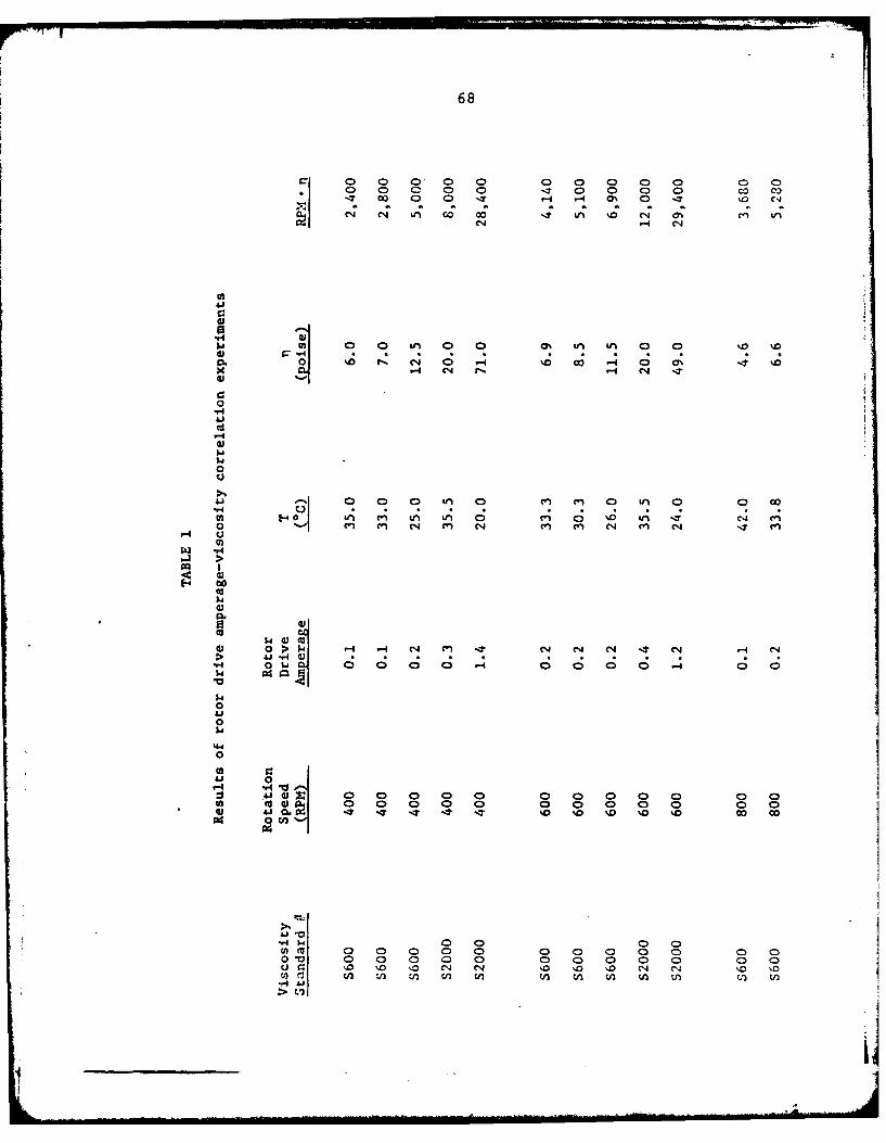
68
('4 (4 U, co 00 -7 LA %0 (N ON en U,(NH (N
41
0
00
a 1M0c0 1-4 * .;C.
04 Hn (Ni r-. H1 (4 -"04.70 '
>
'-4)co
$4 4) t
00
4.a 0o0 0 0 0f 0 4 , 0 0
H4 w
Ell> V)
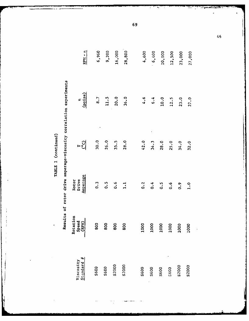
69
46
..-4 r-I CIS cli
004 -40 C4 n r
1-1 C M- V-4 cJ C'J0
0 -ri
$4
41 41e 4 , 00 C~. 0 W~ 1 I 0 t4 ~ J -4 U 4
(4 0 Q~ 0 ) 0 0 Q 0 3 0 0 0 0 -
I.H
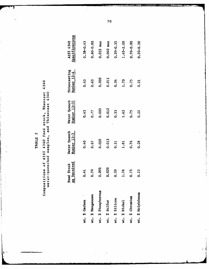
70
0
cn4 cc IO c 9~ Cr 0 Cr,ITO 0 0; 0 C4 0 0
-H* I I tL 0 I14.4 44 0 00 0 rn IT
ro -H 0n 0 C14 %.0 N- c4i
A C; ; C
W "4 tn -4oo en. C, Cr 0 -4 -. 0 Un .- 4
Q~ 04 %0 0 0 cr r r- 0-#~~ 0Q 00-
.xc 0 C C C C
Jd It 4
0(a e
40
~ w0. co'0 0 0 Cr O N '
lCa 43 .i . . .%W' ;4 30 0000. 0 0
0 01-4 -1 n
-4.4
443
00
00 Ai ) 0 0 LM en
43 0:9
41 4) 0) 4 ) 4 ) 4C: 3 . $ 0 4 - 1
0 to 0. : u 4 0 .

71
TABLE 3
Phase micro-hardness of primary solid particles and priorliquid matrix in 4340 Rheocast water quenches, air-cooled
Thixocastings and vermiculite cooled Thixocastings
Primary Solid Particles Prior Liquid Matrix
Knoop KnoopHardness Rockwell C Hardness Rockwell CNumber Conversion Number Conversion
Rheocastwater quenched 542 50 780 62structure
Thixocastair cooled 331 33 741 60structure
Thixocastvermiculite cooled 270 24 458 44structure
Lill
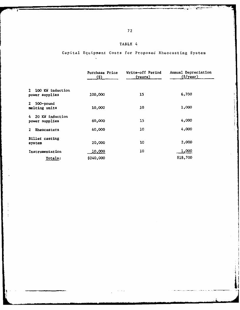
72
TABLE 4
Capital Equipment Costs for Proposed Rheocasting System
Purchase Price Write-off Period Annual Depreciation(years) ($/year)
2 100 KW inductionpower supplies 100,000 15 6,700
2 500-poundmelting units 10,000 10 1,000
4 20 KW induction
power supplies 60,000 15 4,000
2 Rheocasters 40,000 10 4,000
Billet castingsystem 20,000 10 2,000
Instrumentation 10,000 10 1,000
Totals: $240,000 $18,700
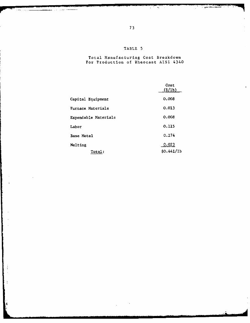
73
TABLE 5
Total Manufacturing Cost BreakdownFor Production of Rheocast AISI 4340
Cost
($/lb)
Capital Equipment 0.008
Furnace Materials 0.013
Expendable Materials 0.008
Labor 0.115
Base Metal 0.274
Melting 0.023
Total: $0.441/lb
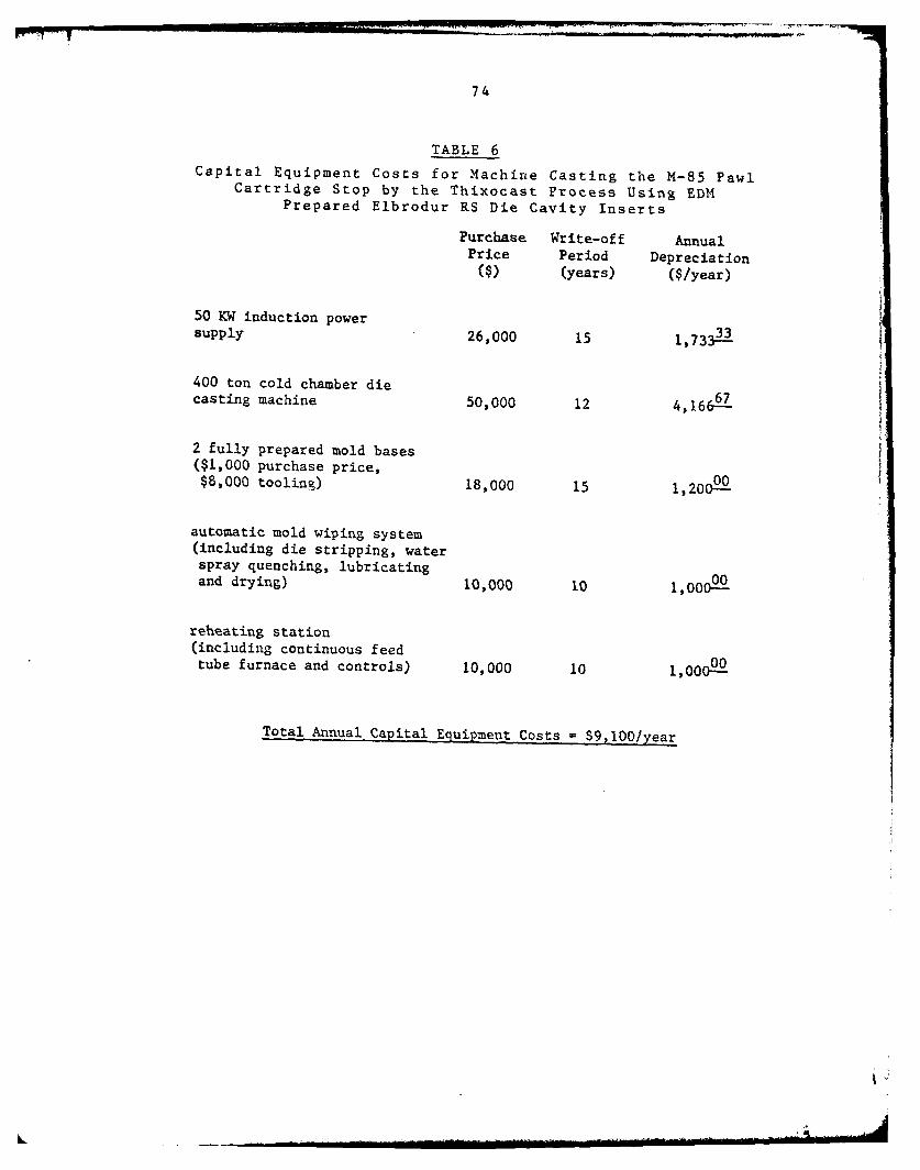
74
TABLE 6Capital Equipment Costs for Machine Casting the M-85 Pawl
Cartridge Stop by the Thixocast Process Using EDMPrepared Elbrodur RS Die Cavity Inserts
Purchase Write-off AnnualPrice Period Depreciation
($) (years) ($/year)
50 KW induction powersupply 26,000 15 1,733 :
400 ton cold chamber diecasting machine 50,000 12 4,1667
2 fully prepared mold bases($1,000 purchase price,
00$8,000 tooling) 18,000 15 1,200-
automatic mold wiping system(including die stripping, waterspray quenching, lubricatingand drying) I0,000 10 1,00=
reheating station(including continuous feedtube furnace and controls) 10,000 10 1,000-
Total Annual Capital Equipment Costs $9,100/year
L

75
TABLE 7
Capital Equipment Costs for Machine Casti:ag the M-85 Pawl,Cartridge Stop by the Thixocast Process Using InvestmentCast and Finished Machined Elbrodur RS Die Cavity Inserts
Purchase Write-off AnnualPrice Period Depreciation
($) (years) ($/year)
50 KW induction powersupply 26,000 15 1,733=-
400 ton cold chamber diecasting machine 50,000 12 4,16667
2 fully prepared mold bases($1,000 purchase price, 00$8,000 tooling) 18,000 15 1,200=-=
automatic mold wiping system(including die stripping, waterspray quenching, lubricating 00and drying) 10,000 10 1,000
reheating station(including continuous feedtube furnace and controls) 10,000 10 1,000-
hobb (tool steel master forinvestment casting die 00cavity inserts) 2,000 10 200-=
Total Annual Capital Equipment Costs - $9,300/year
i;

76
TABLE 8
Total Manufacturing Cost Breakdown forThixocast M-85 Pawl*
Percent of totalmanufacturing
($/year) ($/shot) cost
Capital Equipment 9,100 0.0152 0.65%
Additional Materials 1,000 0.0017 0.07%
Labor 105,000 0.1750 7.49%
Expendable Materials - 0.10 4.28%
Reheating Energy - 0.01 0.43%
Rheocast Metal - 0.726 31.05%
Machine Components - 1.310 56.03%
S2.3379/shot
Utilizing a 16 cavity mold and assuming a 95% casting
efficiency:
Individual Part Manufacturing Cost - $O.1538/casting
Machine casting cartridge stop using EDM prepared
Elbrodur RS die cavity inserts. Annual productionper machine is assumed to be 600,000 shots.Expected machine component lives are estimatedat 10,000 shots.
_ _ _ _ _ _ _ _ _
.4
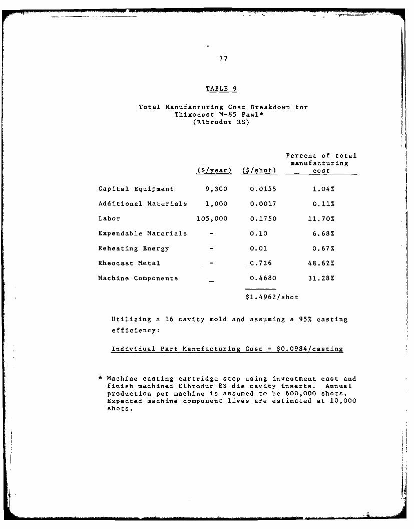
77
TABLE 9
Total Manufacturing Cost Breakdown forThixocast M-85 Pawl*
(Elbrodur RS)
Percent of totalmanufacturing
($/year) ($/shot) cost
Capital Equipment 9,300 0.0155 1.04%
Additional Materials 1,000 0.0017 0.11%
Labor 105,000 0.1750 11.70%
Expendable Materials - 0.10 6.68%
Reheating Energy - 0.01 0.67%
Rheocast Metal - 0.726 48.62%
Machine Components 0.4680 31.28%
$1.4962/shot
Utilizing a 16 cavity mold and assuming a 95% casting
efficiency:
Individual Part Manufacturing Cost $0.0984/casting
Machine casting cartridge stop using investment cast andfinish machined Elbrodur RS die cavity inserts. Annualproduction per machine is assumed to be 600,000 shots.Expected machine component lives are estimated at 10,000shots.
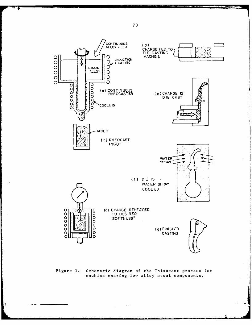
78
CONTINUOUS (d)ALLOY FEED (d
CHARGE FED TODIE CASTING
S INDUCTION MACHINE
O 0 HEATING
0 OLIQUID0 ALLOY 0
0 0
00 (a ) CONTINUOST
0 0--O--) (e).CHARGE IS0 0 DIE CAST
0
WATE SR
OCOOLED
O0 0 (c) CHARGE REHEATED i
0 0 TO DESIRED0 0. "SOFTNESS" ()FNSE0 00 0
0 ~(b 0 (gEFINSHE
iINO CASTING
Figure 1. Schematic diagram of the Thixocast process for Imachine casting low alloy steel components.
WAE
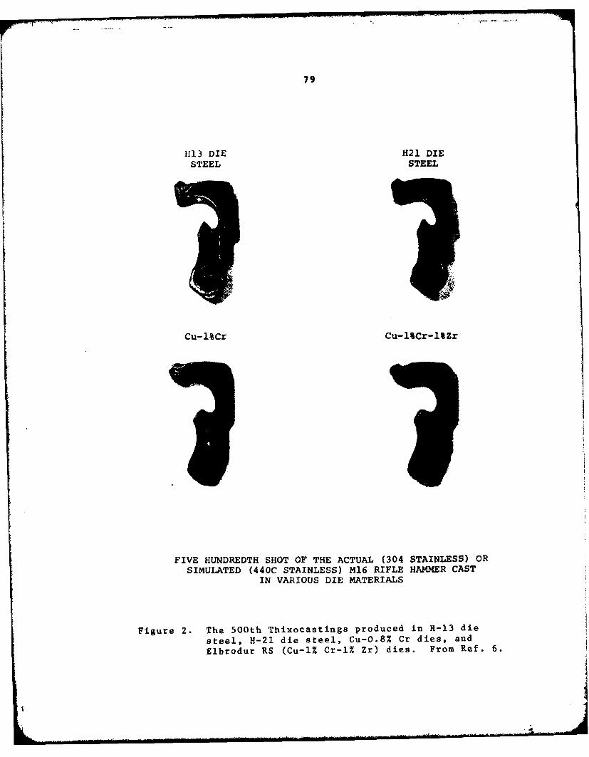
79
1113 DIE H21 DIESTEEL STEEL
Cu-1%Cr Cu-1%Cr-1%Zr
FIVE HUNDREDTH SHOT OF THE ACTUAL (304 STAINLESS) ORSIMUJLATED (440C STAINLESS) M16 RIFLE HAMMER CAST
IN VARIOUS DIE MATERIALS
Figure 2. The 500th Thixocastings produced in H-13 die
steel, H-21 die steel, Cu-0.8% Cr dies, and
Elbrodur RS (Cu-iT. Cr-l% Zr) dies. From Ref. 6.
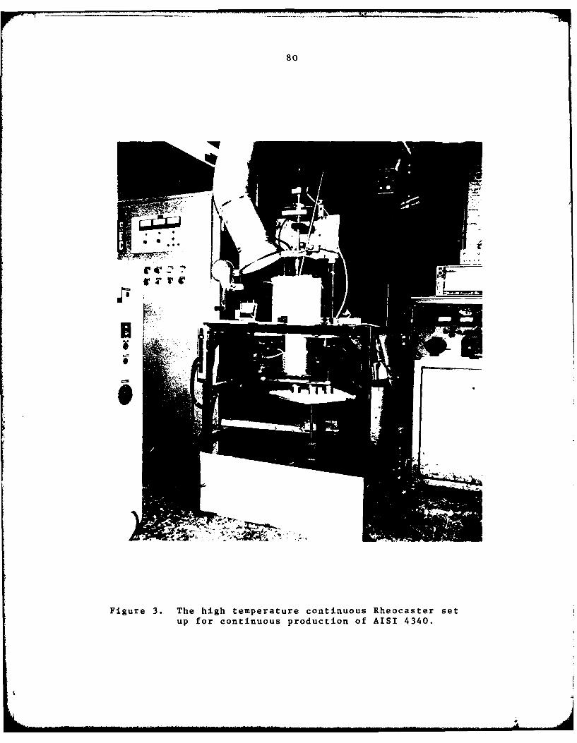
80
T C
Figure 3. The high temperature continuous Rheocaster setup for continuous production of AISI 4340.
'IJ

81
INLETTRANSITE
MOHEN LLO
I CHAMMER
RAMMEDREFRACTORY
ALLOY~MOTE SLRRLERMOYLEV
CCHRAMECROTO
Ar-4% H 2 EQUARTZ TUB
cOniuou RhMMocaEFRCeOR
ALO LRYCRMCSEV
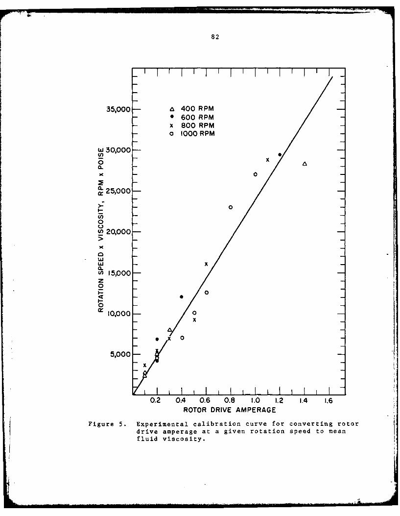
82
35,000 - 400 RPM- 600 RPMx 800 RPMo 1000 RPM
" 30,000 -
00
' 25,000-
>-
(n'00_ 20,000 -
w, iC
u 15,000-z0
0B-
Cr 0,000- 0
nX00
5,000-
X0
0.2 0.4 0.6 0.8 1.0 1.2 1.4 1.6ROTOR DRIVE AMPERAGE
Figure 5. Experimental calibration curve for converting rotordrive amperage at a given rotation speed to meanfluid viscosity.
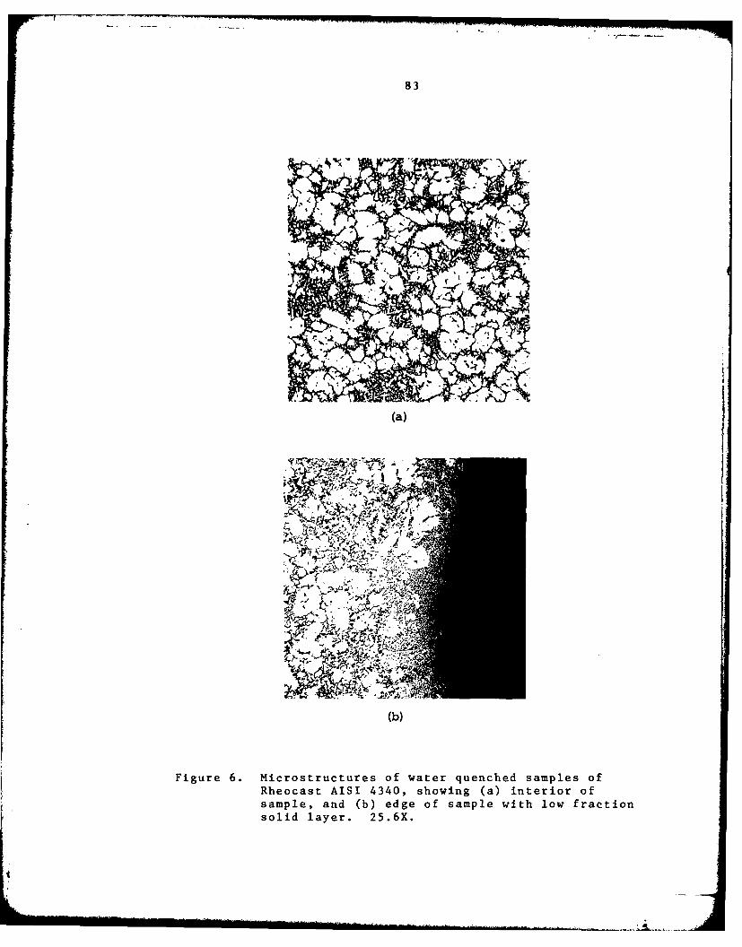
83
AA
'4 7.
474
Figure 6. Microstructures of water quenched samples ofRheocast AISI 4340, showing (a) interior ofsample, and (b) edge of sample with low fractionsolid layer. 25.6X.

84
1.6-
CONTINUOUS PRODUCTION RUNS XX x
I 4 800 RPM xdfs/dt :0.67-0.95 MIN-
1.2 - XXX
0- 8 POINTS
WO. xX ' 9 PO INTS
0x x
00.6- x x
0.4-
0.2-
X
0.10 0.20 0.30 0.40 0.50 0.60VOLUME FRACTION OF PRIMARY SOLID(fs)
Figure 7. Effect of volume fraction of primary solid onthe amperage required to drive thp rotor at800 RPM in Rheocast 4340. Data from continuousproduction runs with solidification rates rangingfrom 0.67 min-1 to 0.95 min-1.
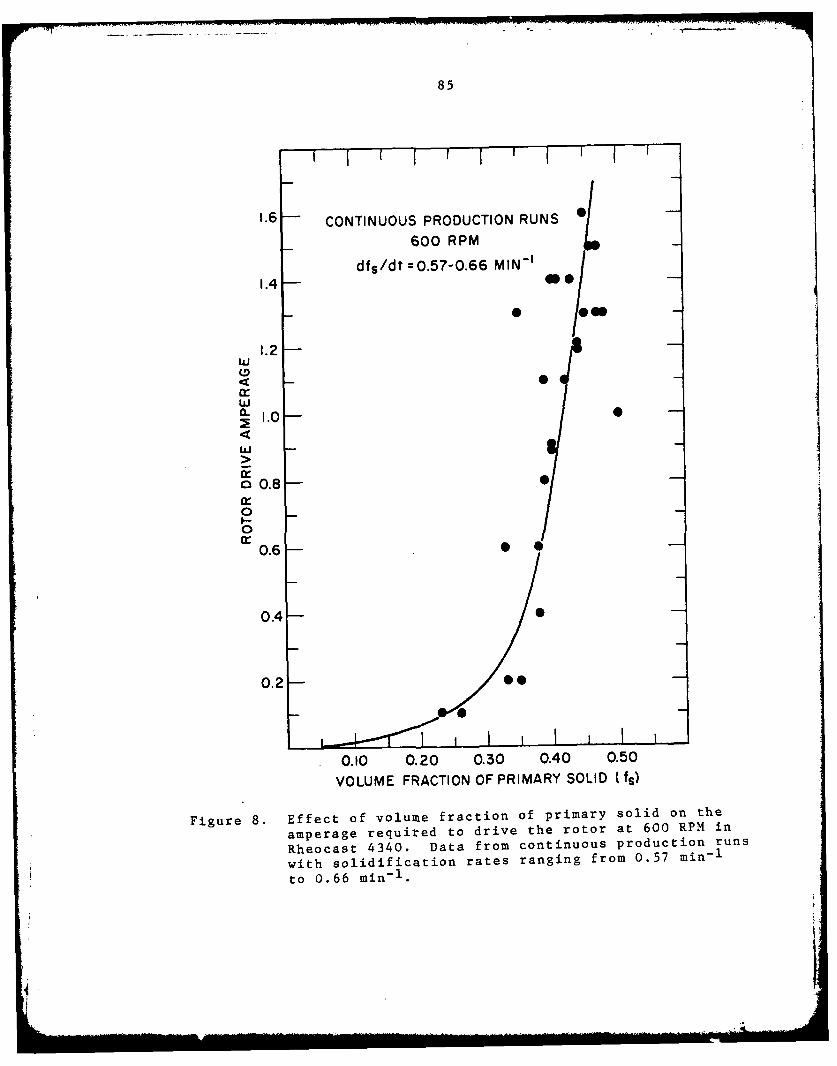
85
' I I ' I '
1.6 -- CONTINUOUS PRODUCTION RUNS
600 RPM
dfs/dt =0.57-0.66 MIN - '
1.4-4
1.2hi
w-
.0a 0.8-
0 _I-
0
0.6 0 0
0.4 -
0.2-O-
0.10 0.20 0.30 0.40 0.50
VOLUME FRACTION OF PRIMARY SOLID {fs)
Figure 8. Effect of volume fraction of primary solid on the
amperage required to drive the rotor at 600 RPM in
Rheocast 4340. Data from continuous production runs
with solidification rates ranging from 0.57 min - 1
to 0.66 min -1 .
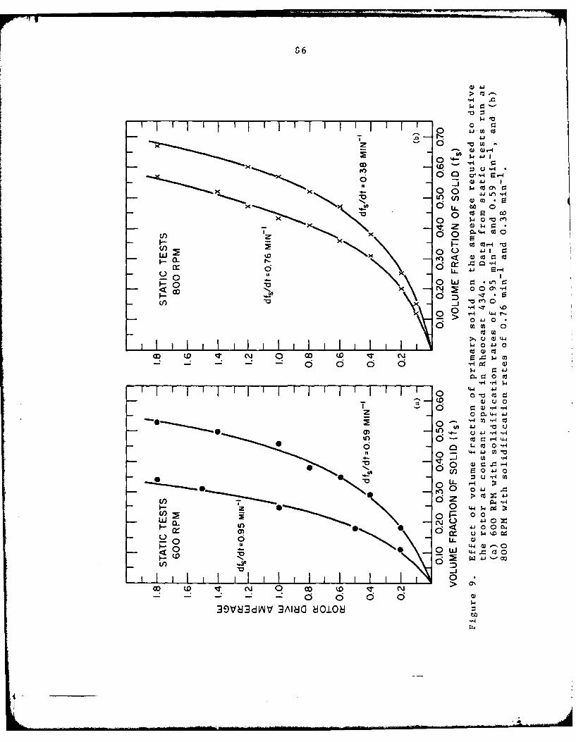
0. cd
Vo n
OD (0
4J ldW4 44
U) (0 4J0 M
V)00 o-i -0
0 41 1
- c C
U, GO0__a 5- -;r -0 0rz
-4 r-d0 M 0
4 0 4J 0
11111 jlj w11 111
0
0 44U 4-i 1
o0 K3clC0I - ' .4-4 W J
* '~J0 -Li '-
04. 0
s00 00 0u
6 zW
w 00
~~~ (0 C L(04
0~ ci U.0
-'.4 0
1-j
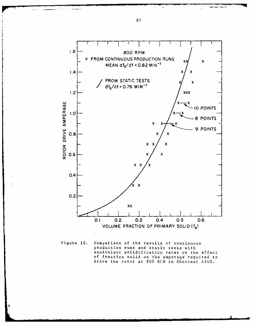
87
1.6 -800 RPM
X FROM CONTINUOUS PRODUCTION RUNS x
MEAN dfs/dt = 0.82 MIN - ' x -1.4 XX
I FROM STATIC TESTS x
dfs/dt 0.76 MIN - '1.2 XXX
I0 POINTSa: 1.0 - ( .x0- 8 POINTS
-- X X X -
W 9 POINTS? 0.8- x X
n- -- X X X -
0o 0.6- x x
-- X X X
0.4-
0.2-
0.1 0.2 0.3 0.4 0.5 0.6VOLUME FRACTION OF PRIMARY SOLID US)
Figure 10. Comparison of the results of continuousproduction runs and static test.s withequivalent solidification rates on the effectof fraction solid on the amperage required todrive the rotor at 800 RIM in Rheocast 4340.
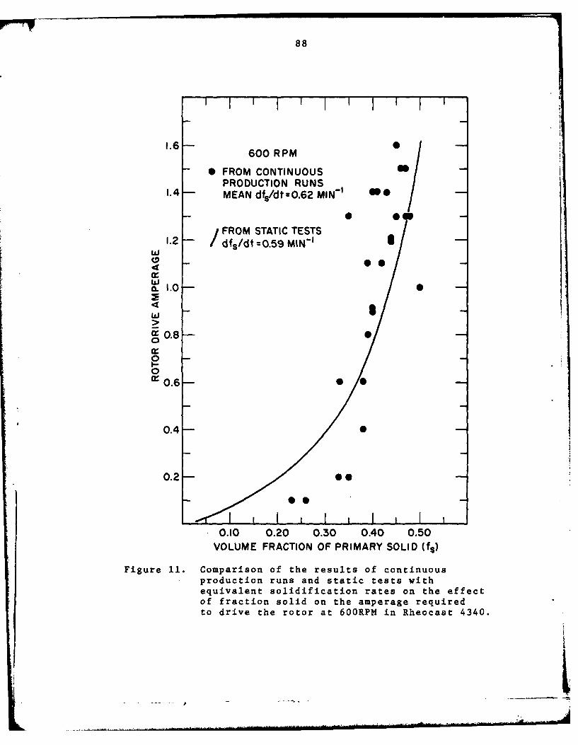
88
' I iI I I I I J
1.6600 RPM /
- FROM CONTINUOUSPRODUCTION RUNS /
1.4 MEAN dfs/dt=0.62 MIN-/
1.FROM STATIC TESTS1.2 -- /dfs/dt =0.59 MIN - ' 1/-
I. 1o.0v
S0.8
0r0.6 __
0.4-
0.2 -°-- O0
0.10 0.20 0.30 0.40 0.50VOLUME FRACTION OF PRIMARY SOLID (Us)
Figure 11. Comparison of the results of continuousproduction runs and static tests withequivalent solidification rates on the effectof fraction solid on the amperage requiredto drive the rotor at 600RPM in Rheocast 4340.
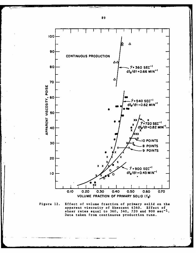
89
100-
90-CONTINUOUS PRODUCTION
80so- Y 360 SEC-df 5/dt -0.66 MIN-'
0
0
0
60 - -w x 7-72 SEC-'
w @* d/dO.62M1 MI*x7
IL 0 x
xx0 '10I POINTS
30x x x, 8 POINTS* * 9x x POINTS
0 x xxxx
10 0d fs/dt =0.43 M IN'
0
0I I 1I I I I I I i I I I
0.10 0.20 0.30 0.40 0.50 0.60 0.70VOLUME FRACTION OF PRIMARY SOLID 0%e)
Figure 12. Effect of volume fraction of primary solid on theapparent viscosity of Rheocast 4340. Effect ofshear rates equal to 360, 540, 720 and 900 sec-1 .Data taken from continuous production runs.
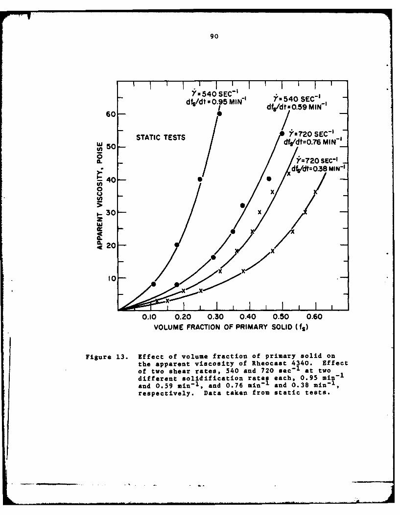
90
Y540OSEC'54SE-df5/dt -O.95 MIN 75 SC
60- 1 dfs/dt=0.59MIN-'
-STATIC TESTS Yr720 SEC'_UW 50-df,/dtzO.76 MIN 1
a>: d~dt: 0.38 MIN-'
40-(0 0x
30 x
200
0.0 0.0 0.30 0.40 0.50 0 .60VOLUME FRACTION OF PRIMARY SOLID Ct,)
Figure 13. Effect of volume fraction of primary solid onthe apparent viscosity of Rheocast 4340. Effectof two shear rates, 540 and 720 sec-1 at twodifferent solidification rates each, 0.95 i1and 0.59 min-1 , and 0.76 min-, and 0.38 min-1 ,respectively. Data taken from static tests.

91
z 360 SEC -O 180 540 SEC -
x 720 SEC -
- 0 900 SEC -1
160
w_j
S140- =2 E-
I0
p120w
1000
0.25 0.35 0.45 0.55VOLUME FRACTION OF PRIMARY SOLID (fs)
Figure 14. Effect of volume fraction of primary solid on theeffective primary solid particle radius in Rheocast4340. Effect of shear rates equal to 360, 540, 720and 900 sec - 1 .

r 92
(a) (b)
41
Figure 15. Microstructures of Rheocast AISI 4340 slurriesproduced with a shear rate of 720 sec-1 and con-
taining volume fractions solid of (a) 0.53, (b) 0.46,(c) 0.35, and (d) 0.25. 25.6X.
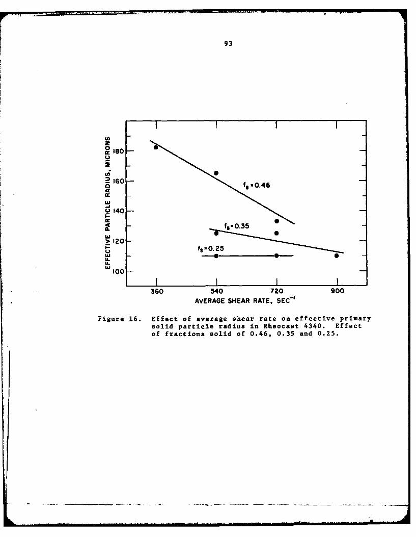
93
0
S160
0 140-P-
Y03IL-wI> 120
P fS10.25
w100F
360 540 720 900AVERAGE SHEAR RATE, SEC'1
Figure 16. Effect of average shear rate on effective primarysolid particle radius in Rheocast 4340. Effectof fractions solid of 0.46, 0.35 and 0.25.
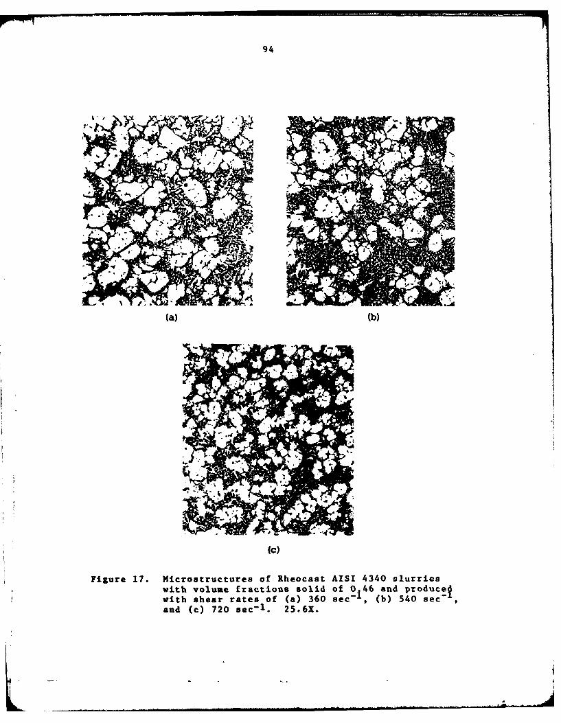
94
((b)
Figure 17. Microstructures of Rheocast AISI 4340 slurrieswith volume fractions solid of 0 46 and produce~with shear rates of (a) 360 sec'i, (b) 540 sec-f
and (c) 720 sec-1 . 25.6X.

95
Figure 18. The Thixocast reheat station, including theinductively powered reheat furnace and theSoftness Indicator.
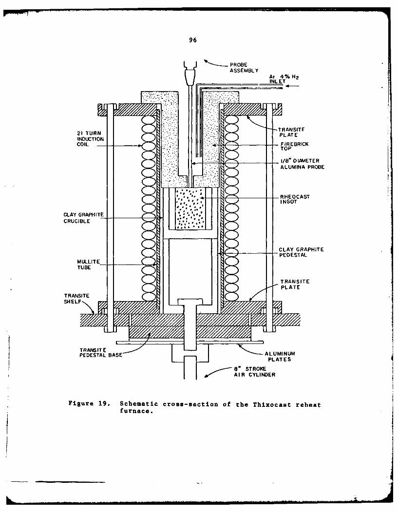
96
PROBEASSEMBLY
Ar 4% H2INL ET
-- 1/8" D IA&4ETERALUMINA PROBE
- RHEOCAST
CLAY GRAPH'ITECRUCIBLE
CLAY GRAPHITE-PEDESTAL
TRARSNITTE
PLATE
80 STROKEwl- AIR CYLINDER
Figure 19. Schematic cross-section of the Thixocast reheatfurnace.
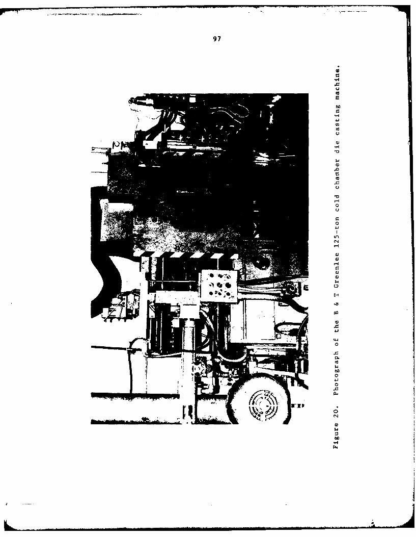
97
U'
4-i
0u
0
.
CNI
0
4
WIN

98
I
Figure 21. Photograph of the external water spray systemfor die cooling.
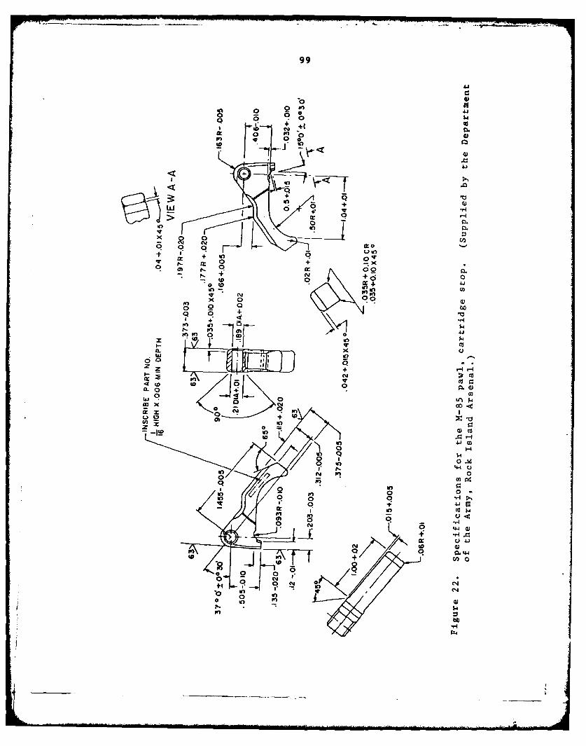
99
4=1
0 4O0 2f0 4.1
%D m 0ad
it. 0 in _0'
- ". + -t( + s
0 -~ 0
ona
x 0
0 "r 0
+ 0C! + 00
O m r. " -x
- + • 0 0- (0 0
w 4. 4
x 0 " ,
0 oo. r
Q 0,-
++
a.
+ 4+
(n NbI
00V-
in~ 000
1 0 i0
In0 0C -I, +41.
in r
0 44a4.4
ecm0 0 44
to pn + '-4
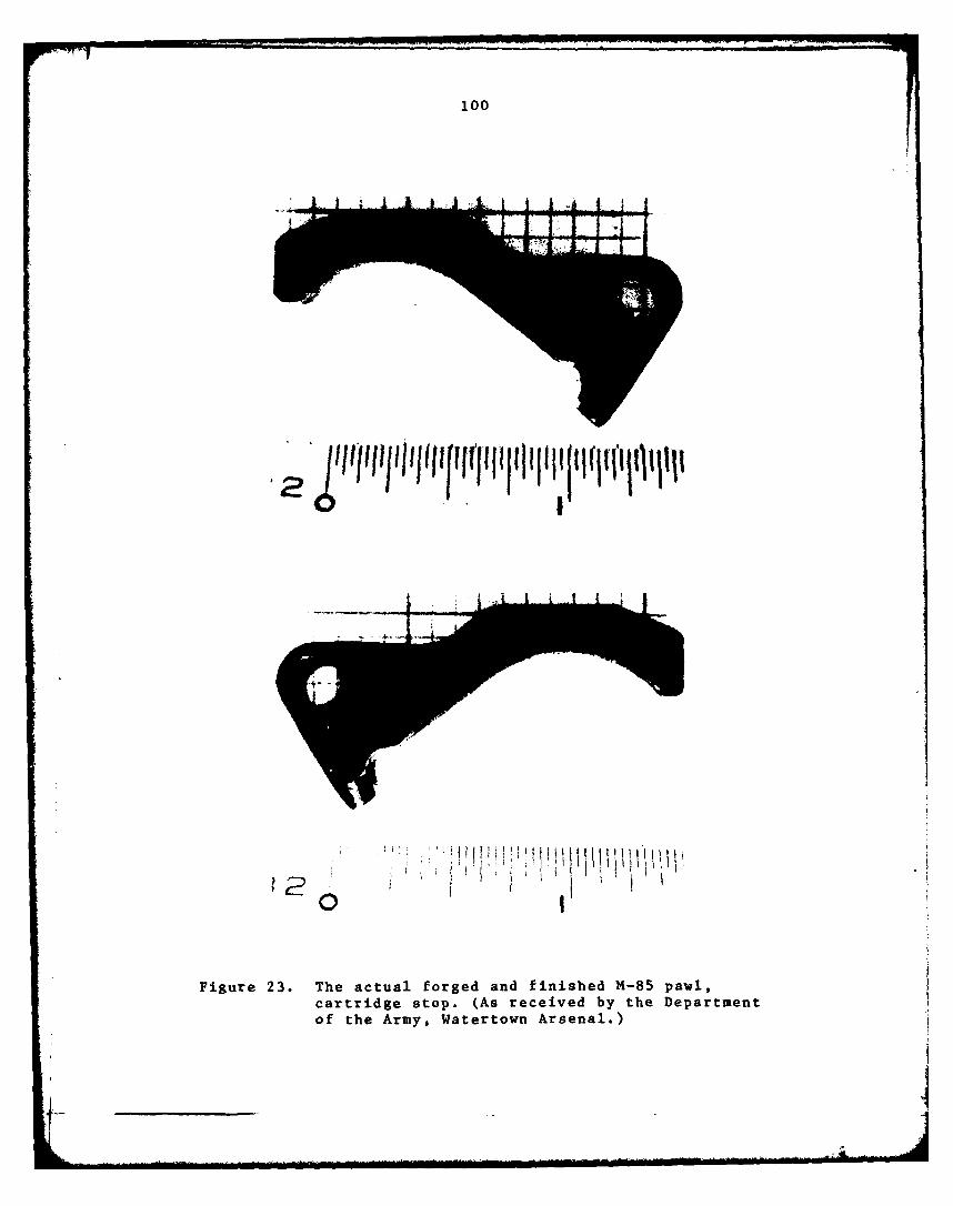
100
Figure 23. The actual forged and finished M4-85 pawl,cartridge stop. (As received by the Departmentof the Army, Watertown Arsenal.)
101
Figure 24. Photograph of the entire M-85 die casting,including overflows, runner and biscuit.
102
0
0
041
Cd
.
0
-
103
Figure 26. The Thixcocast M4-85 pawl, cartridge stop,shown in the finished condition.
104
-A >
w 0 004 w 0
to,% 0 "
r 0 U C
UWO
c 0 0U0-00 u 9 u
4 OH 0-I
u 0 u a1.v40 00 -s 4 1 r0-4 0 : r-
asU 0 U v4
10 u00 0 w-
U0 009
w U 0 O w
00$39 0 0LY v 4 E 4 Hv4 .0
9: cl 0 0ILU 4 H 4 -0.r
I- w0 14 0 ) 0 0
05U000 000
.0 3
0 .3 Q80 93 U 0I4
100U H0
4j U 4 0%
O000-A O0P4'Jo0
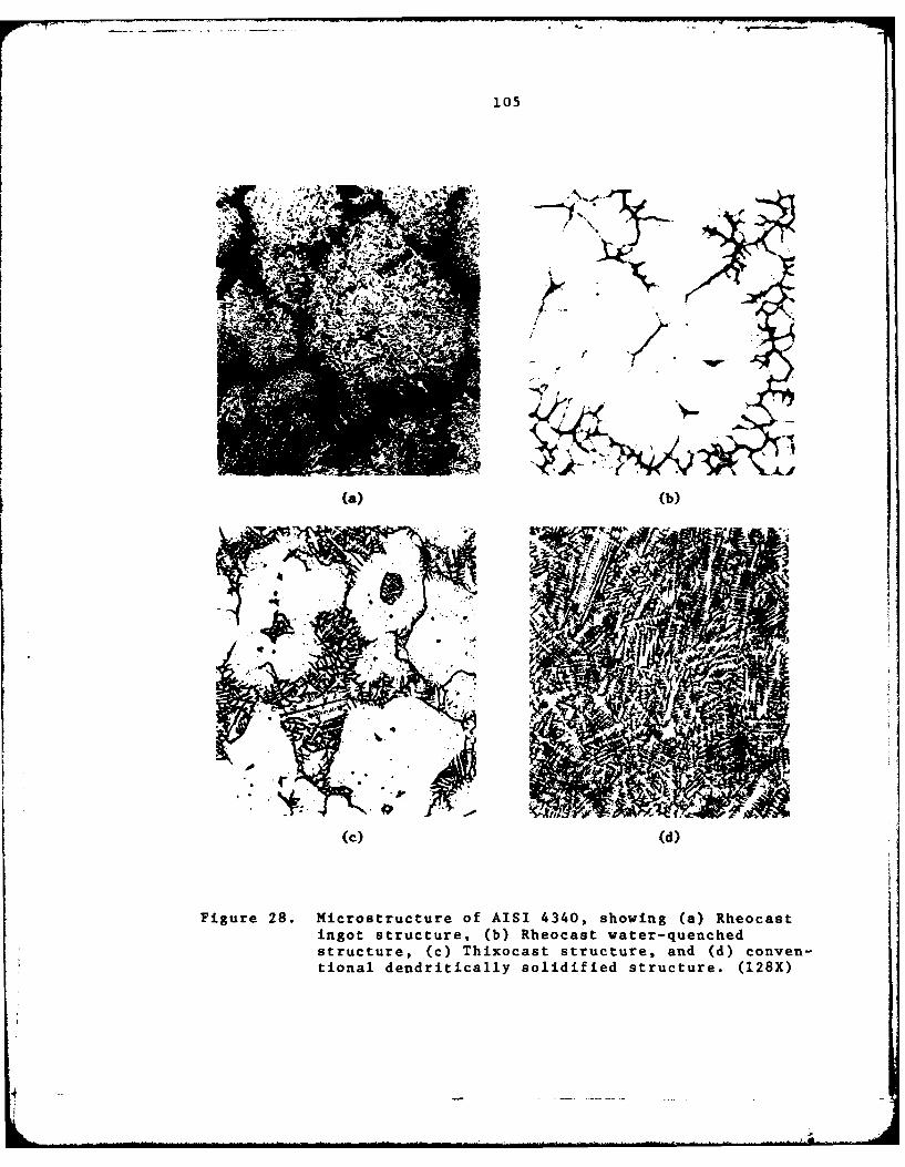
105
(a) (b)
(c) (d)
Figure 28. Microstructure of AISI 4340, showing (a) Rheocastingot structure, (b) Rheocast water-quenchedstructure, (c) Thixocast structure, and (d) conven-tional dendritically solidified structure. (128X)
14
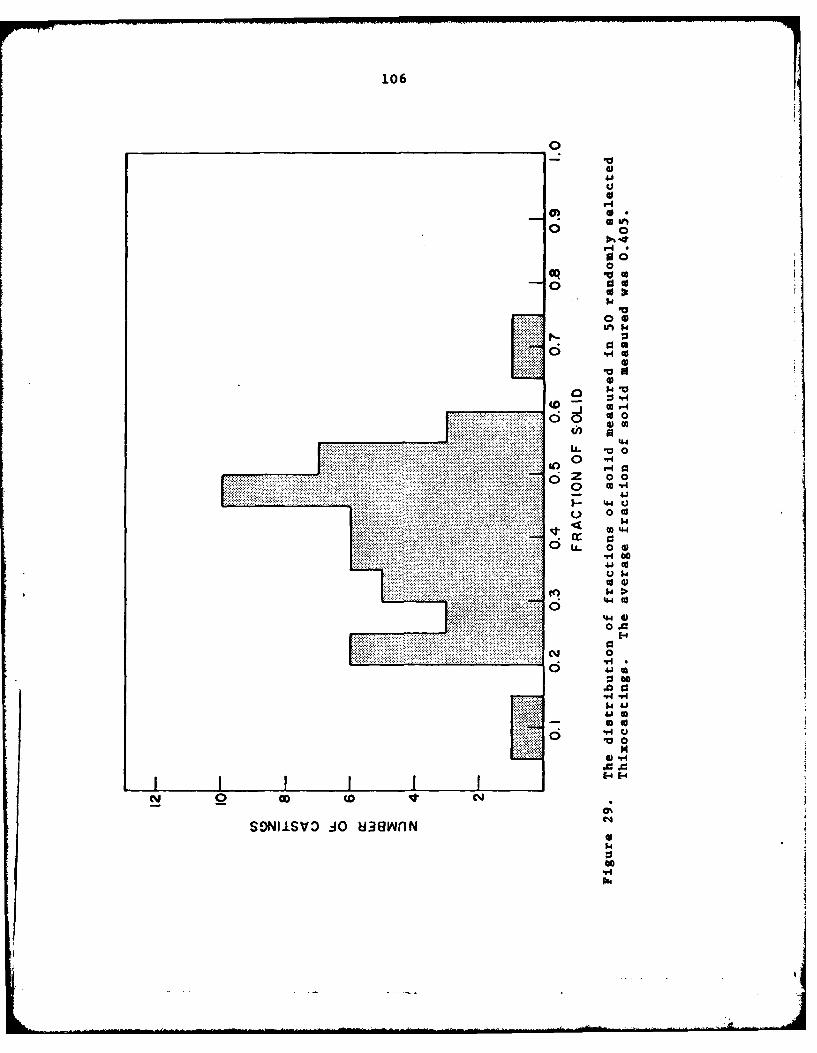
106
"4
0
0 91
o o 0
4~
0 0
0 C
o o4i - 0 41
( c) 0)
05.0
1-4
V 0
.00
4
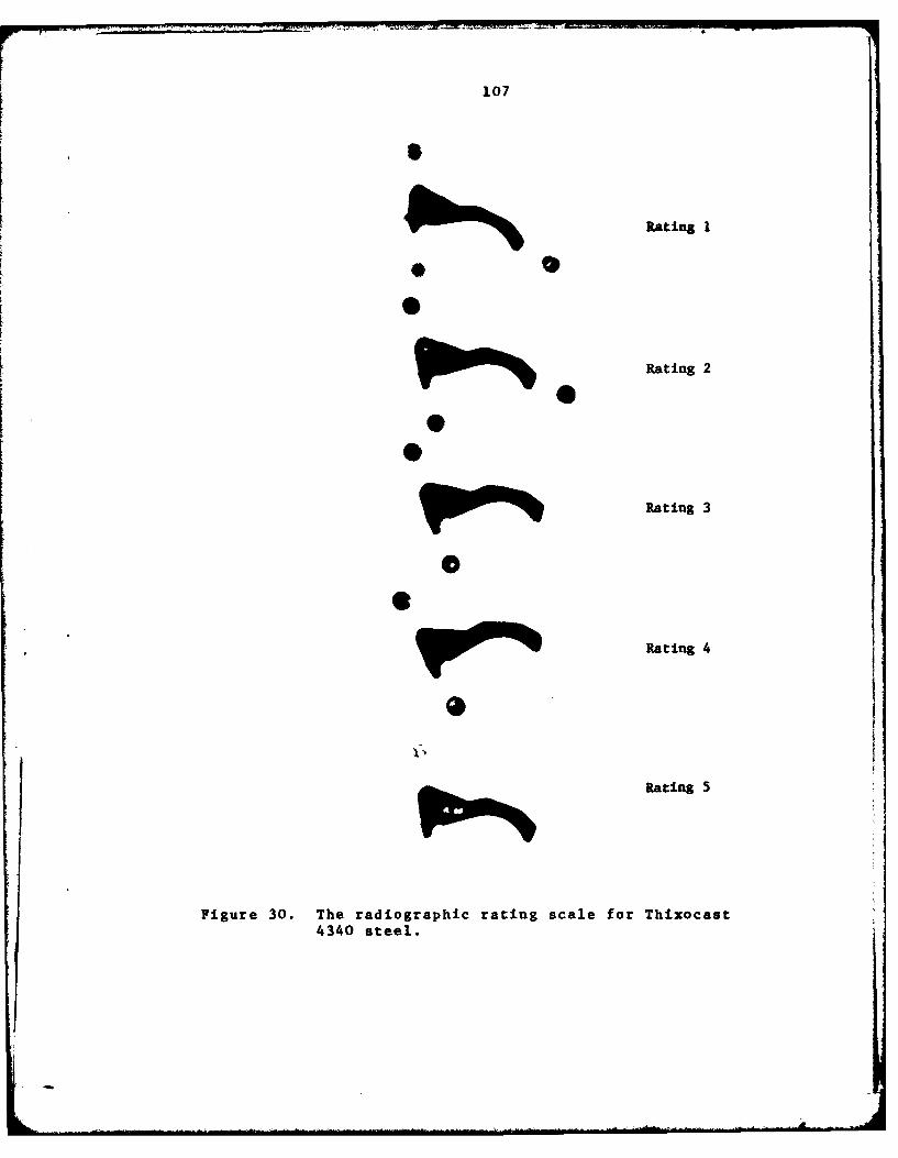
107
S
Rating I
0
Rating 20
0
R
Rating 3
0
~Rating 4
Rating 5
Figure 30. The radiographic rating scale for Thixocast4340 steel.
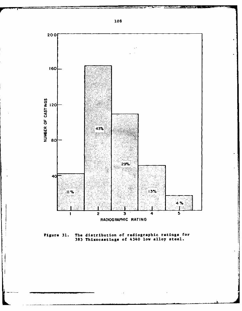
108
200
160-
Z120-
U.
43%
40
4 %
WRADIOGRAPHIC RATING
Figure 31. The distribution of radiographic ratings for383 Thizocastings of 4340 low alloy steel.j
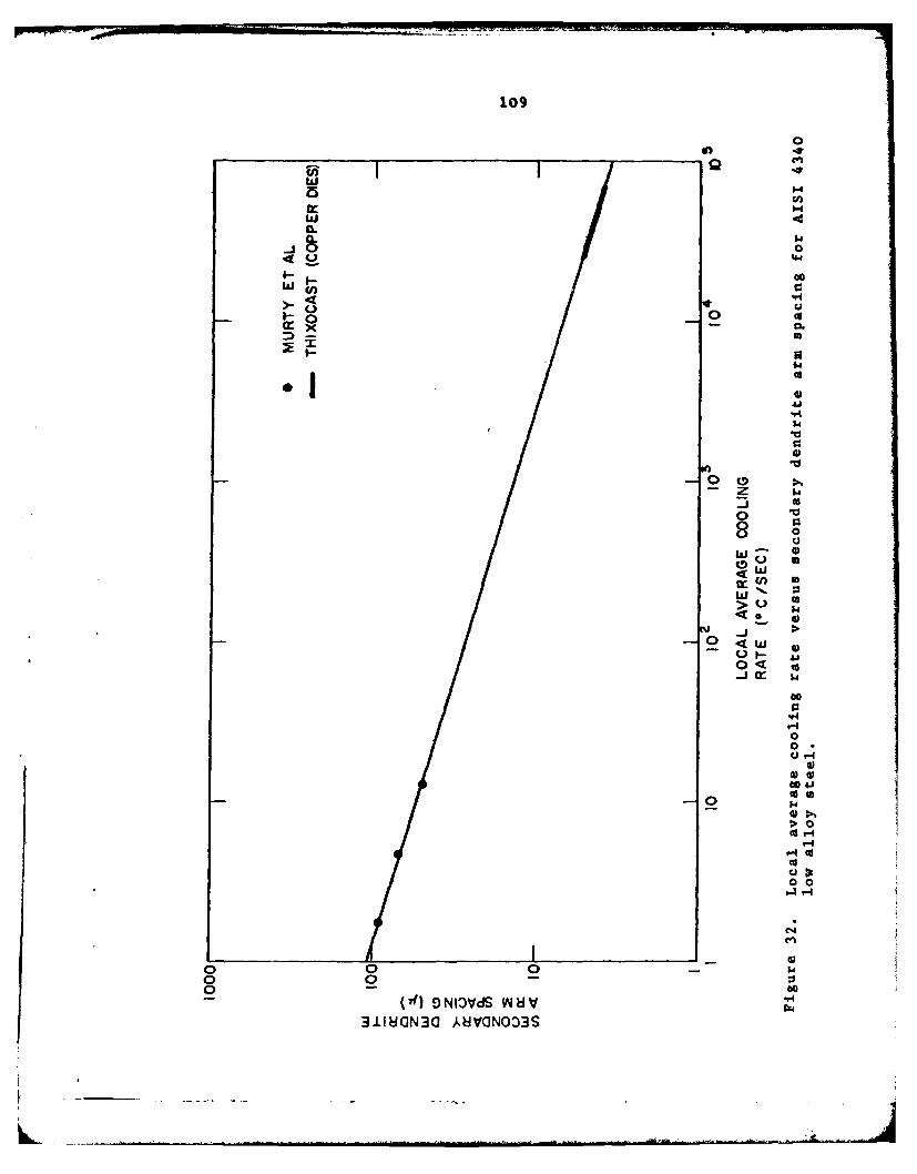
109
0
'41
000In C3
100XI
-0000 %
- 0
0
UJ
U3
14
60
00
>> 04. $4
044 4'cor
0 0
0 0 14
600A
SNIO~S WH 4311MN30 HVIG003
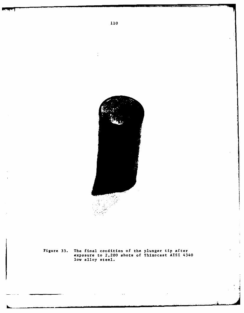
110
Figure 33. The final condition of the plunger tip afterexposure to 2,200 shots of Thixocast AISI 4340low alloy steel.
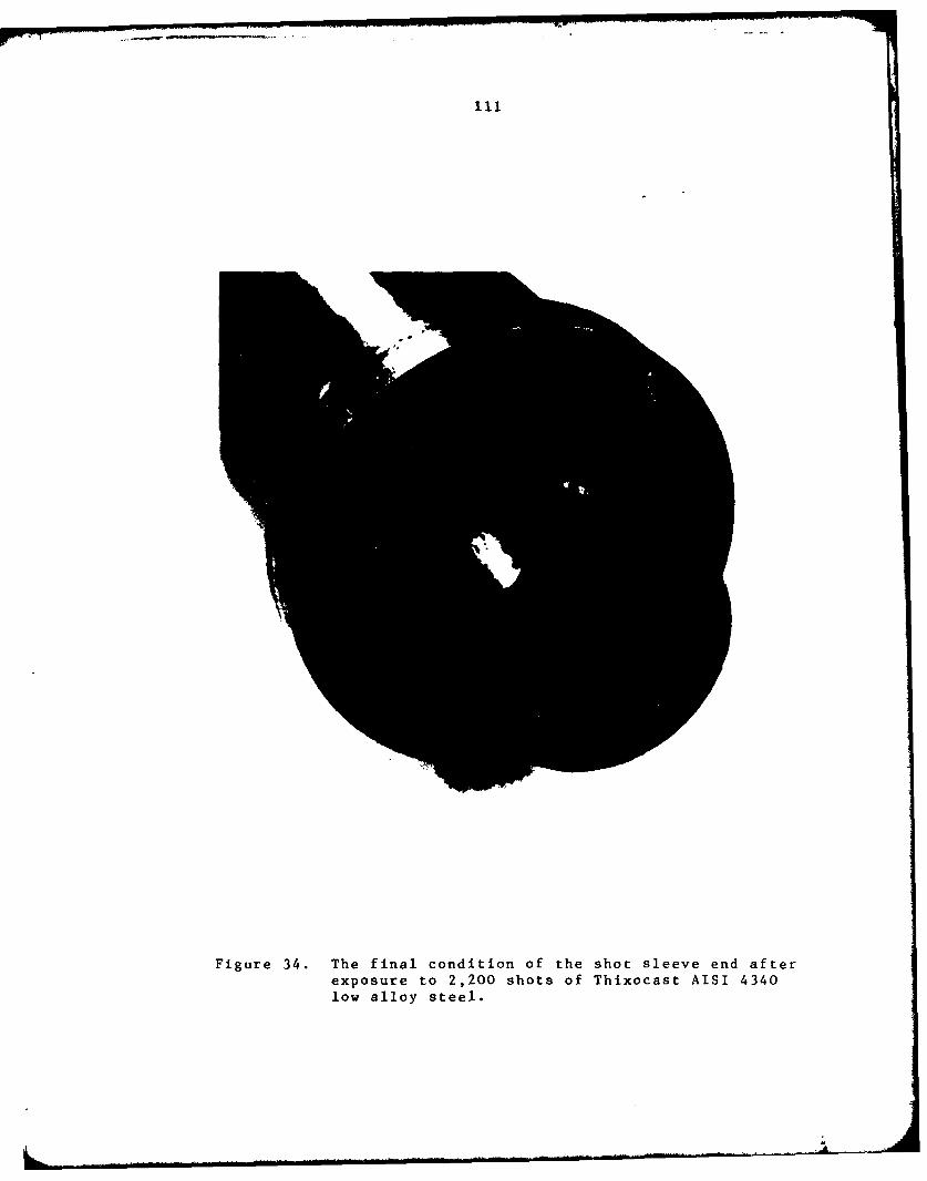
Figure 34. The final condition of the shot sleeve end afterexposure to 2,200 shots of Thixocast AISI 4340low alloy steel.
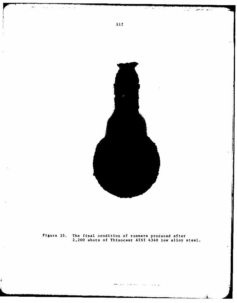
112
Figure 35. The final condition of runners produced after2,200 shots of Thixocast AISI 4340 low alloy steel.

113
12 SHOTS 499 SHOTS 994 SHOTS
41.
1482 SHOTS 1900 SHOTS 2191 SHOTS
THIXOCASTINGS OF THE M-85 PAWL, CARTRIDGE STOP4340 LOW ALLOY STEEL/ ELBRODUR RS DIES
Figure 36. Sequence of AISI 4340 low alloy steel Thixocastingsproduced at various intervals in the 2,200 shot dielife study for Elbrodur RS copper alloy dies.
. . . . . . . . . . ..4I I . . . ... . . . . . . . . .. . . .. . ."
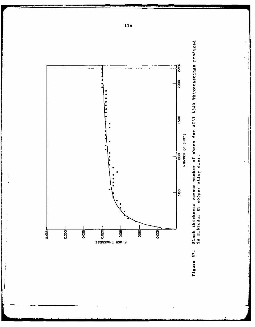
114
*
0
8
0.
44
t0 000
o
00a
(n 0
0 $
0 14n 0>1 0
.0 0
05 0 C5 0
A i
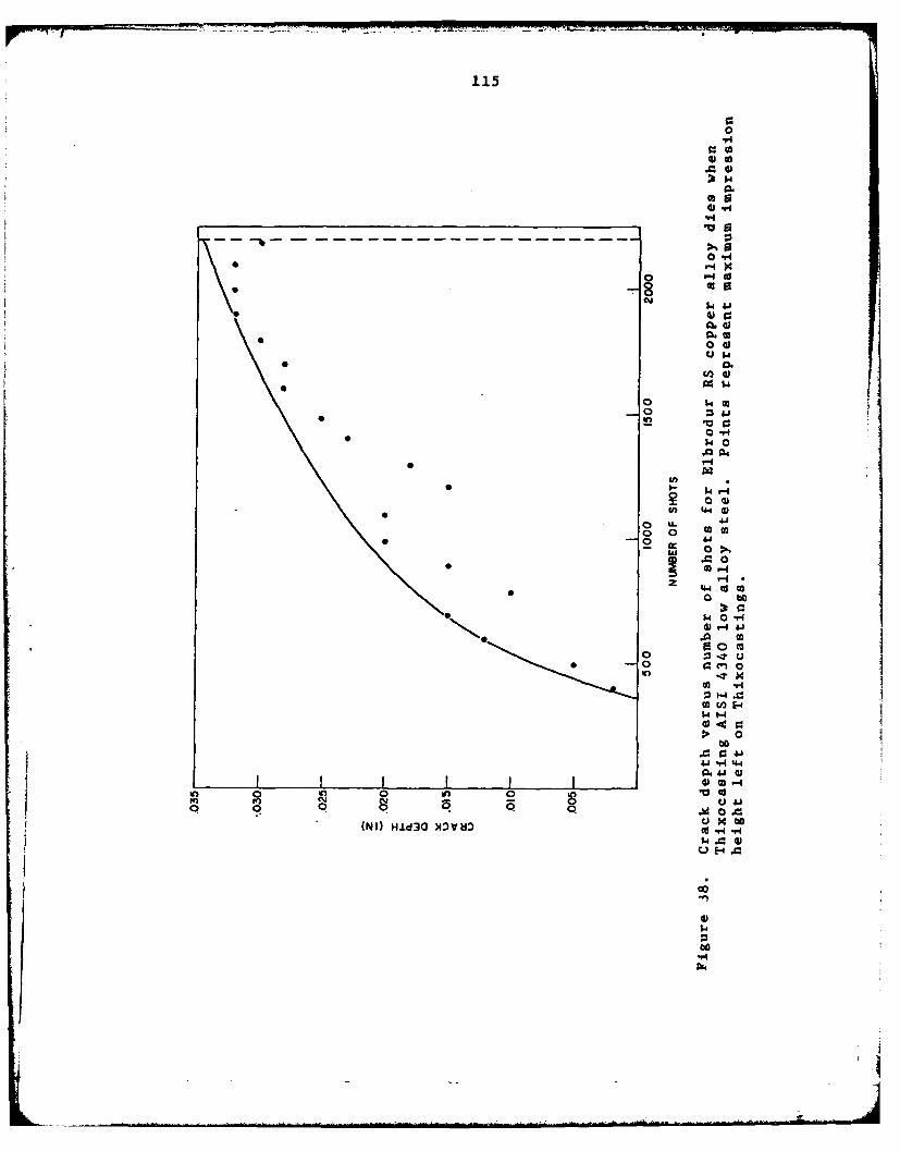
115
0*14
0 "
0.
1
0o '4
• N O
00
0 0
M 1-4
In
z 0o0
0 InI I.4®j
o 0 V0
C -40 H-> 0
404 4
W 04
4.1... ..-0 04
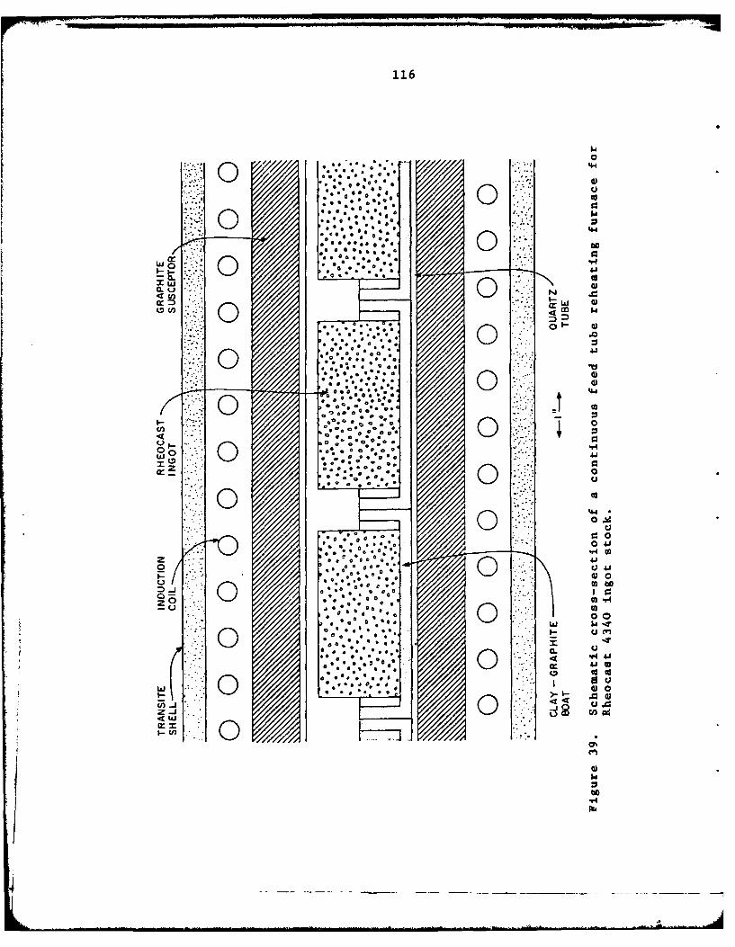
116
0 cc
(9;3w 0
I-I-
7:00
0 0
w00
0o CLJ
a oo
o* . 0o.)
4W ..

117
kn 000
0.o o m 0 8H0m -. - 0
00
w
ILI
- I.-
10) LLL 0
0. 0)I- UI
ww
0- 0+0
z w.
00
ZI :6t C, ~
O N0
0410 1
0 0 0 I 000 0 0 0 0 0 00
CD 0 0 0 w 0N~L to040 N to
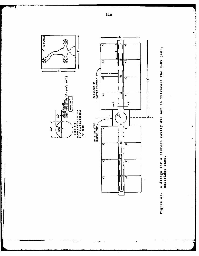
118
01004V
If 0.
ID *I
ble
* 00C N
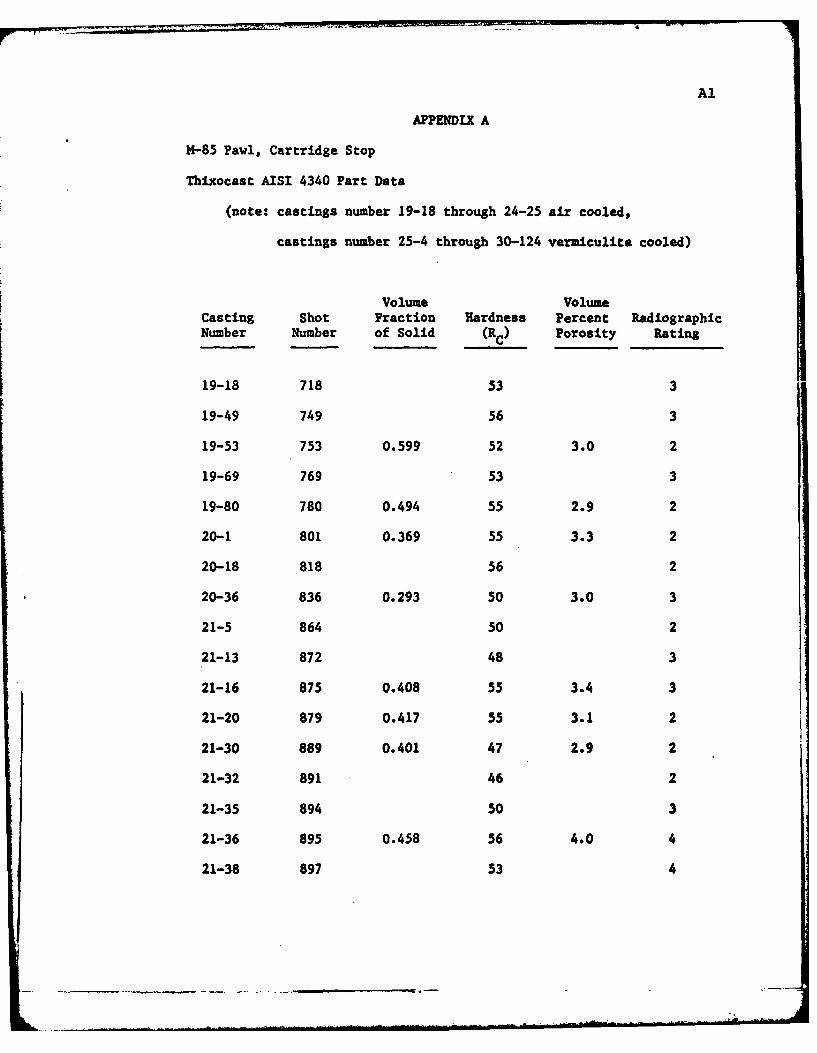
Al
APPENDTX A
*-85 Pawl, Cartridge Stop
Thixocast AISI 4340 Part Data
(note: castings number 19-18 through 24-25 air cooled,
castings number 25-4 through 30-124 vermiculite cooled)
Volume VolumeCasting Shot Fraction Hardness Percent RadiographicNumber Number of Solid (RC) Porosity Rating
19-18 718 53 3
19-49 749 56 3
19-53 753 0.599 52 3.0 2
19-69 769 53 3
19-80 780 0.494 55 2.9 2
20-1 801 0.369 55 3.3 2
20-18 818 56 2
20-36 836 0.293 50 3.0 3
21-5 864 50 2
21-13 872 48 3
21-16 875 0.408 55 3.4 3
21-20 879 0.417 55 3.1 2
21-30 889 0.401 47 2.9 2
21-32 891 46 2
21-35 894 50 3
21-36 895 0.458 56 4.0 4
21-38 897 53 4
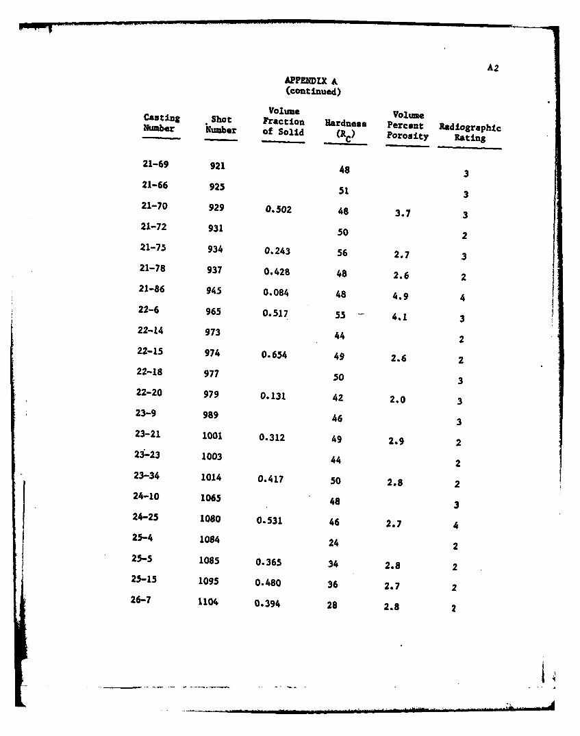
A2
APPENDIX &(continued)
Volume VolumeCasting Shot Fraction Hardness Percent RadiographicNumber Number of Solid (Rc) Porosity Rating
21-69 921 48 321-66 925 51 321-70 929 0.502 48 3.7 321-72 931 50 2
21-75 934 0.243 56 2.7 321-78 937 0.428 48 2.6 221-86 945 0.084 48 4.9 422-6 965 0.517 55 4.1 322-14 973 44 222-15 974 0.654 49 2.6 222-18 977 50 322-20 979 0.131 42 2.0 323-9 989 46 323-21 1001 0.312 49 2.9 223-23 1003 44 223-34 1014 0.417 50 2.8 224-10 1065 48 324-25 1080 0.531 46 2.7 425-4 1084 24 225-5 1085 0.365 34 2.8 225-15 1095 0.480 36 2.7 226-7 1104 0.394 28 2.8 2
A1
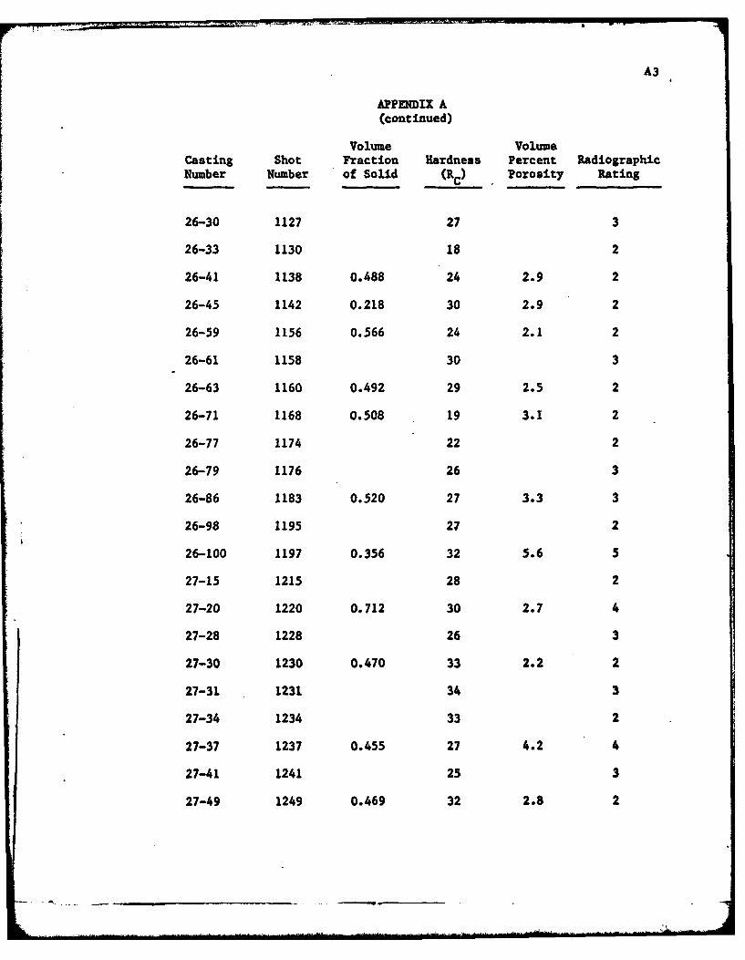
A3
APPENDIX A(continued)
Volume VolumeCasting Shot Fraction Hardness Percent RadiographicNumber Number of Solid (RC) Porosity Rating
26-30 1127 27 3
26-33 1130 18 2
26-41 1138 0.488 24 2.9 2
26-45 1142 0.218 30 2.9 2
26-59 1156 0.566 24 2.1 2
26-61 1158 30 3
26-63 1160 0.492 29 2.5 2
26-71 1168 0.508 19 3.1 2
26-77 1174 22 2
26-79 1176 26 3
26-86 1183 0.520 27 3.3 3
26-98 1195 27 2
26-100 1197 0.356 32 5.6 5
27-15 1215 28 2
27-20 1220 0.712 30 2.7 4
27-28 1228 26 3
27-30 1230 0.470 33 2.2 2
27-31 1231 34 3
27-34 1234 33 2
27-37 1237 0.455 27 4.2 4
27-41 1241 25 3
27-49 1249 0.469 32 2.8 2
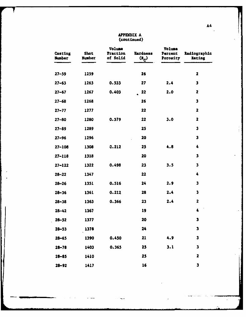
A4
APPENDIX A(continued)
Volume VolumeCasting Shot Fraction Hardness Percent RadiographicNumber Number of Solid (RC) Porosity Rating
27-59 1259 26 2
27-63 1263 0.533 27 2.4 3
27-67 1267 0.403 22 2.0 2
27-68 1268 26 3
27-77 1277 22 2
27-80 1280 0.579 22 3.0 2
27-89 1289 25 3
27-96 1296 20 3
27-108 1308 0.212 25 4.8 4
27-118 1318 20 3
27-122 1322 0.498 23 3.5 3
28-22 1347 22 4
28-26 1351 0.516 24 2.9 3
28-36 1361 0.212 28 2.4 3
28-38 1363 0.366 23 2.4 2
28-42 1367 19 4
28-52 1377 20 3
28-53 1378 24 3
28-65 1390 0.450 21 4.9 3
28-78 1403 0.365 25 3.1 3
28-85 1410 25 2
28-92 1417 16 3
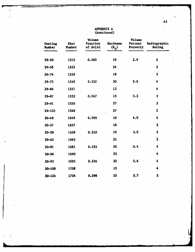
A5
APPENDIX A(continued)
Volume VolumeCasting shot Fraction Hardness Percent RadiographicNumber Number of Solid (Cc) Porosity Rating
29-50 1515 0.305 19 3.9 4
29-58 1523 24 3
26-74 1539 18 3
29-75 1540 0.332 30 5.6 4
29-86 1551 13 4
29-87 1552 0.247 15 3.2 3
29-91 1556 27 3
29-103 1568 27 2
30-49 1649 0.299 19 4.0 4
30-57 1657 i8 3
30-58 1658 0.310 19 3.0 3
30-63 1663 21 3
30-81 1681 0.333 20 5.4 4
30-90 1690 23 4
30-93 1693 0.236 32 5.6 4
30-108 1708 15 4
30-124 1724 0.298 25 2.7 3
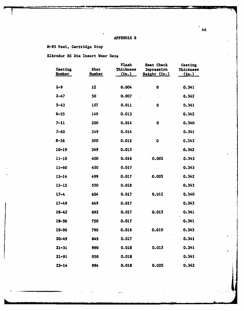
A6
APPENDIX B
14-85 Pawl, Cartridge Stop
Kibrodur RS Die Insert Wear Data
Flash Heat Check CastingCasting Shot Thickness Impression Thickness
Number Number (in. Height (in.) (in.
2-9 12 0.004 0 0.341
2-47 50 0.007 0.342
5-43 107 0.011 0 0.341
6-35 149 0.013 0.342
7-11 200 0.014 0 0.340
7-60 249 0.014 0.341
8-36 300 0.015 0 0.343
10-19 349 0.015 0.342
11-10 400 0.016 0.002 0.343
11-60 450 0.017 0.343
13-14 499 0.017 0.005 0.342
15-15 550 0.018 0.343
17-4 604 0.017 0.012 0.340
17-49 649 0.017 0.343
18-42 692 0.017 0.015 0.341
19-50 750 0.017 0.341
19-90 790 0.016 0.010 0.343
20-49 849 0.017 0.341
21-31 890 0.018 0.015 0.341
21-91 950 0.018 0.341
23-14 994 0.018 0.020 0.342

A7
APPENDIX B(continued)
Flash Heat Check CastingCasting Shot Thickness Impression ThicknessNumber Number (in.) Height (in.) (in.)
23-71 1051 0.018 0.341
26-3 1100 0.019 0.020 0.342
26-53 1150 0.019 0.342
27-5 1205 0.018 0.015 0.343
27-50 1250 0.019 0.341
27-101 1301 0.019 0.018 0.342
28-25 1350 0.019 0.341
28-75 1400 0.018 0.023 0.342
28-124 1449 0.018 0.342
29-17 1482 0.019 0.025 0.342
29-83 1548 0.019 0.341
30-5 1605 0.019 0.028 0.343
30-50 1650 0.019 0.343
30-100 1700 0.019 0.028 0.341
31-3 1753 0.019 0.343
31-48 1798 0.019 0.030 0.341
31-101 1851 0.019 0.343
31-150 1900 0.019 0.032 0.341
32-50 1950 0.020 0.341
32-97 1997 0.020 0.032 0.343
32-149 2049 0.020 0.341
33-46 2096 0.020 0.032 0.342
61i
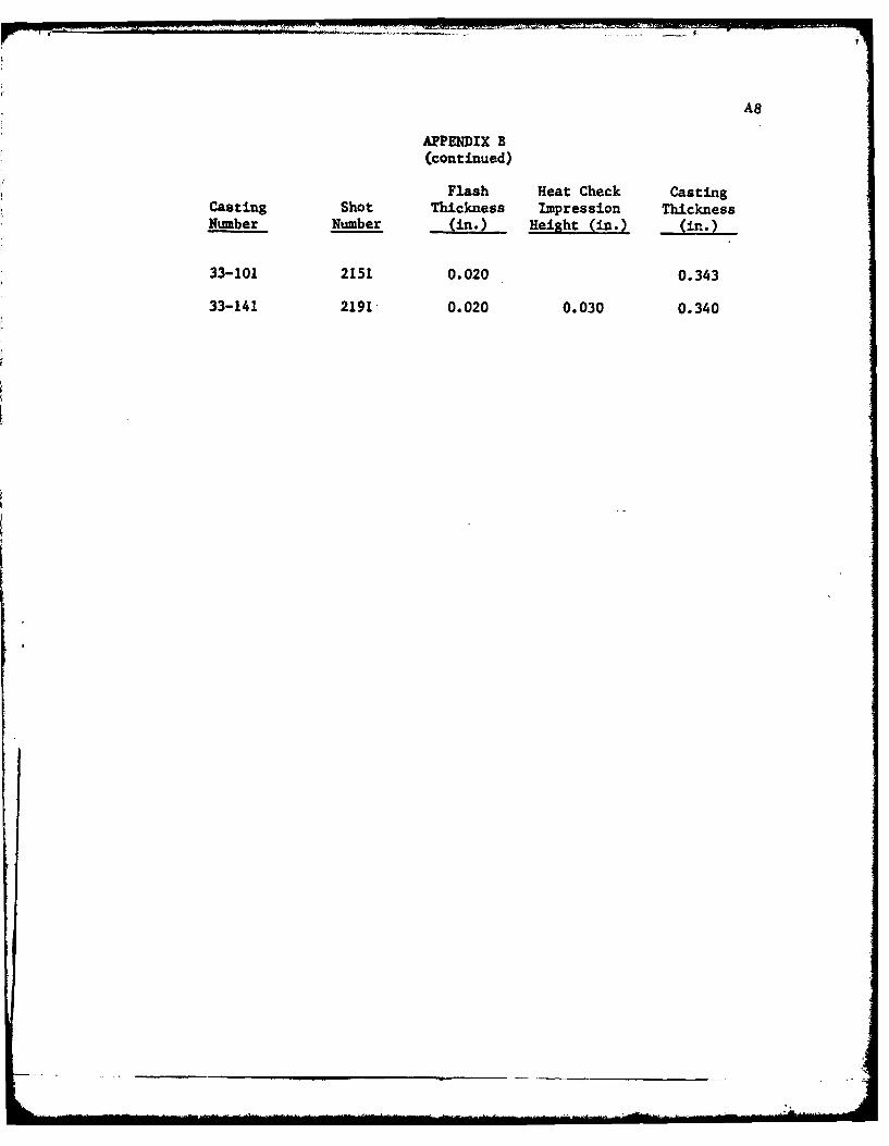
A8
APPENDIX B(continued)
Flash Heat Check CastingCasting Shot Thickness Impression ThicknessNumber Number (in.) Height (in.) (in.)
33-101 2151 0.020 0.343
33-141 2191- 0.020 0.030 0.340

ARPA
a -
DISTRIBUTION LIST
No. ofCopies To
I Office of the Director, Defense Research and Engineering, The Pentagon,Washington, D. C. 20301
12 Commander, Defense Documentation Center, Cameron Station, Building 5,5010 Duke Street, Alexandria, Virginia 22314
1 Metals and Ceramics Information Center, Battelle Columbus Laboratories,505 King Avenue, Columbus, Ohio 43201
Chief of Research and Development, Department of the Army,Washington, D. C. 20310
2 ATTN: Physical and Engineering Sciences Division
C6mmander, Army Research Office, P. 0. Box 12211, ResearchTriangle Park, North Carolina 27709
1" ATTN: Information Processing Office
Commander, U. S. Army Materiel Development and Readiness Command,5001 Eisenhower Avenue, Alexandria, Virginia 22333
1 ATTN: DRCDE-TC
Commander, U. S. Army Electronics Command, Fort Monmouth, " ew Jersey 07703 I1 ATTN: DRSEL-GG-DDI DRSEL-GG-DM
Commander, U. S. Army Missile Command, Redstone Arsenal, Alabama 358091 ATTN: Technical Library1 DRSMI-RSM, Mr. E. J. Wheelahan
Commander, U. S. Army Armament Command, Rock Island, Illinois 612012 ATTN: Technical Library1 DRSAR-SC, Dr. C. M. Hudson1 DRSAR-PPW-PB, Mr. Francis X. Walter
Commander, U. S. Army Tank-Automotive Research and Development Command,Warren, Michigan 48090
2 ATTN: DRDTA, Research Library Branch
Commander, White Sands Missile Range, New Mexico 88002I ATTN: STEWS-WS -VT
Commander, Aberdeen Proving Ground, Maryland 210051 ATTN: STEAP-TL, Bldg. 305
Corm.ndc-r, Franl-ford Arsenal, Philadelphia, Penns)'lvania 191371 ATTN: Library, H1300, BI. 51-21 5ARFA-L300, Mr. J. Corrie
I

ARPA
No. of--
Copies To
Comrander, Picatinny Arsenal, Dover, New Jersey 07801
1 ATTN: "SARPA-RT-S
Co.nmander, Redstone Scientific Information Center, U. S. Army MissileComnand, Redstone Arsenal, Alabama 35809
4 ATTN: DRSMI-RBLD, Document Section
Commander, Watervliet Arsenal, Watervliet, New York 12189I ATMN: SARWV'-RDT, Technical Information Services Office
Commander, U. S. Army Foreign Science and Technology Center,220 7th Street, N. E., Charlottesville, Virginia 22901
I ATTN: DRXST-SD2
Director, Eustis Directorate, U. S. Army Air Mobility Research andDevelopment Laboratory, Fort Eustis, Virginia 23604
1 ATTN: Mr. J. Robinson, SAVDL-EU-SS
Librarian, U. S. Army Aviation School Library, Fort Rucker, Alabama 363601 ATN': Building 5907
Naval Research Laboratory, Washington, D. C. 203751 ATTN: Dr. J. H. Krafft - Code S430
Chief of Naval Research, Arlington, Virginia 222171 ATTN: Code 471
Air Force Materials Laboratory, ,'right-Patterson Air Force Base, Ohio 454332 ATTN: AFML/MX E/E. Morrissey1 AFML/LC1 AFML/LLP/D. M. Forney, Jr.I AFML/MBC/Mr. Stanley Schulnan
National Aeronautics and Space Administration, Washington, D. C. 205461 ATTN: Mr. B. G. AchharnmerI Mr. G. C. Deutsch - Code RR-l
National Aeronautics and Space Administration, Marshall Space FlightCenter, Huntsville, Alabama 35812
I ATTN: R-PMVE-M, R. J. Schwinghamer1 S&E-ME--.St, Mr. W. A. Wilson, Building 4720
Wyman-Gordon Company, Worcester, Massachusetts 01601I ATN: Technical Library
Defense Advanced Research Projects Agency, 1400 Wilson Boulevard,Arlington, Virginia 22209
5 ATT;: Dr. E. C. van Peuth
ARPA
N-
No. ofCopies To
National Science Foundation, 1800 G Street, Washington, D. C. 205501 ATTN: Dr. Robert Re)nik
General Electric Company, Corporate Research and Development,Schenectady, New York 12301
5 AYN: Mr. F. X. Gigliotti, Jr.
Hitchiner Manufacturing Co., Inc., Elm Street, Milford, New Hampshire 030555 ATTN: Mr. G. D. Chandler,
Abex Corporation, Research Center, Mahwah, New Jersey 074305 ATTN: H. R. Larson
Massachusetts Institute of Technology, Dept. of Metallurgy and MaterialsScience, Cambridge, Massachusetts 02139
5 ATTN: Dr. Merton C. Fleming
TRW Equipment, TRW Inc., 23555 Euclid Avenue, Cleveland, Ohio 441171 ATTN: Elizabeth Barrett, T/M 5417
Depcsits & Composites inc., 1821 Michael Faraday Drive,Reston, Virginia 22090
I ATTN: Richard E. Engdahl, President
1 Dr. Maurice Sinnott, University of Michigan, Assoc. Dir. of Engineering,Ann Arbor, Michigan 48104
I Fred E. Ziter, Adirondack Steel Casting Co., Shaker Road,Watervliet, New York 12189
1 Dr. Raymond J. Bratton, Westinghouse Electric Corporation ResearchLaboratory, Pittsburgh, Pennsylvania 15235
1 W. M. Spurgeon, Director, Mfg., Quality Control' Home Systems,Program Management Center, Bendix Research Laboratories, Bendix Center,Southfield, Michigan 48075
I S. T. Wlodek, Director of Stellite R&D, Stellite Division, Cabot Corporation,1020 West Park Avenue, Kokomo, Indiana 46901
1 Mr. William A. Butler, Contract Administrator, Microwave Associates, Inc.,Burlington, Massachusetts 01803
1 Mr. John A. Ulrich, Sr. Vice-President, Chamberlain ,ManufacturinR Corp.,Waterloo, Iowa 5070S
I A. V. Ill.vn, Technical Director, Babcock & Wilcox, Old Savannah Road,Augusta, Georgia 30903
ARPA
io. ofCopies To
1 Mr. W. J. Welsch (Code 224), Naval Materials Industry Resources Office,N.A.E.C., Building "0537, Philadelphia, Pennsylvania 19112
1 Mr. R. E. Cross, Federal Die Casting Co., 2222 Elston Avenue,Chicago, Illinois 60614
1 Captain Ebenezer F. Porter, 2618 S. Lynn Street, Arlington, Virginia 22202
1 Mr. Charles E. Bates, Head, Metallurgy Section, Southern Research Institute,2000 Ninth Avenue, South, Birmingham, Alaba.na 35205
1 Mr. R. F. Kirby, Chief, Materials Engineering Dept., Dept. 93-39M,Airesearch Manufacturing Company of Arizona, 402 South 36th Street,P. 0. Box 5217, Phoenix, Arizona S5010
1 Dr. Mervin T. Rowley, American Foundry Men's Society, Golf & Wolf Roads,Dei Plaines, Illinois 60016
I William R. Freeman, Jr., Howmet Corporation, Vice President and TechnicalDirector, Tcchnical Center, Gas Turbine Components Group, 699 Benston Road,Wh-teha]l, Michigan 49461
1 Dole A. Marek, General Motors Corporation, Detroit Diesel Allison,4700 W 10th Street, Indianapolis, Indiana 46206
General Dynanics, Convair Aerospace Division, P. 0. Box 748,Ft. Worth, Texas 76101
1 ATTN: Mfg. Engineering Technical Library
I Dr. Robert Mehrabian, Dept. of Metallurgy & Mining Engineering,University of Illinois, Urbana, Illinois 61801
I Robert McNally, Research Library, Special Metals Corporation,Middle Settlement Road New Hartford, New York 13413
Watertown, Massachusetts 02172
2 ATTN : DRXIR-PLI DRXMR-PRI DRXMR-API DRXIR-CTI DRX.IR-X1 DRXM.IR-ER
Vs t.-.- -
r a... - rII I I
II t Z I T t - - .g u -i i " . . o.P oi. .... ... ...
.1
1... iL , -<, -+ i ' *+ o. . . 1 • . .1=.
no ~ ~ ~ ~ _ I,44404 .2
* -. - o . ++ . , .o+ 4.o o.,!o0.. -o.. .
i--+s 'o. mm~ . 1-., : - 004
a' -c.-"5 1 - t 2.-. . o.00 1. .. . .|
-..u. .....b . ..c..... 01.. .=.. ,+. . . . . .. . - . + ~ . . 0+...4 + ; <,+. . . .- . 00. 0.. .0.4 ; .4 0 - , 0 .4. ... . .. 0-I
Il I
.4- "1c . * eN~ .o .o . . -c.
II 0
-+. .. . . . ,=8 . .. I . - . .0 u ... 0... 0. +4.-c 0*..4I . . 4 . -0... .0 u+..4.. .ff 4+ Af.'f440J l . 4440 .fl
°....4 004 A40u,
-I 0- 04. .1.0 .fl =~ 0 0 .. . . . .404 , . .+, € . , 0.-,, 000 • Ic 0-® ., "+, -.. 00 0 . .4+l0 04 fl 4*0, + - 001o4,. .Qfl,, .0 -.4* Io
4*0.. 0 . ... . .. .. . u .. .. 0.. 0000 ..,- .4 . . .. 4.-c .0 0 0O' 404* .. 4. u fl-.A .. g1..0,4*40, .... . . .. . 0 .. . .. . . . 0...*-c... . ,'
Ou4* u *
- o . . .4.... .. ... 000. .... . c00-. 4 - .1 .'04 .cl 0
Mo Z. m , , J ) i i
0.4.-400.. . 4fl flfl=.0.A . .40,..,l t 0 , ouA.4.4 -c 4..40.41004 . 0 -.. ,0 -Ik.uu.t ,J4* .',4* 0. . .. 00. cO .44.ccl.I .44 0* .4, = .2 . 00 01' . 4 .40+
0 ~llm"+ c2,044fie2040fiA.4 + m~0 0eh "4 .o.0 4-4e. m~ *04'1.0 00.4.4.044 0k,0e
3, 00.0 + 01 0.4 00+.400 a ,- ..... oooo.......... e~i .. ... 000I 0uc0 ol
. it 1I
0 Z - 1
L. R. QL.1 . -.. . . . . ..0.;0.0..f4f I
II
.40-O 40 0 .0 4* .4.4 .40 04 0. 40,0P 2:313 5...4 t .. a 0. K Z00 - - . .4
10 ~ ~ ~ ~ ~ o 10 B 0 4 4 l : c 4u f . ~ : :
01.~~~~~~~~~ 8~l 04.00-4 440 . 4-~~~~ ~~~~ * '2: .0-000.
0- - - - 0 . 00 4 0~ 4* * 4O O0tEO 4
.2 94. - tf 4 f 4 u 1 - - - I 44 4 0 4 . . . A 0 0 * .
.41. . -4 '0 flf 0 0, l u 4-. I 0. 0 .0 -c - 4 40 * fl .4 44..


![HIGH SPEED STEEL PRODUCED THROUGH CONVENTIONAL CASTING … · conventional ingot casting and Osprey process are indicated [3]. pressure and temperature are raised simultaneously [6]](https://img.dokumen.tips/doc/110x75/5f0257097e708231d403c93e/high-speed-steel-produced-through-conventional-casting-conventional-ingot-casting.jpg)