Embed Size (px)
Citation preview

This document downloaded from vulcanhammer.net vulcanhammer.info
Chet Aero Marine
Don’t forget to visit our companion site http://www.vulcanhammer.org
Use subject to the terms and conditions of the respective websites.

. W~14i
INSTRUCTION REPORT GL-92-3 . . .". ,Jlii.~ '~ ,; iJJL
DESCRIPTION AND APPLICATION OF DUAL MASS DYNAMIC CONE PENETROMETER
by
Steve L. Webster, Richard H. Grau, Thomas P. Williams
Geotechnical Laboratory
DEPARTMENT OF THE ARMY Waterways Experiment Station, Corps of Engineers
3909 Halls Ferry Road, Vicksburg, Mississippi 39180-6199
May 1992
Final Report
Approved For Public Release; Distribution Is Unlimited
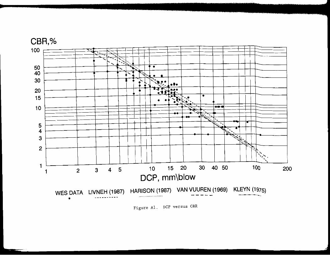
Prepared tor DEPARTMENT OF THE ARMY US Army Corps of Engineers
Washington, DC 20314-1000
Under Project AT40, Work Unit RC-003

REPORT DOCUMENTATION PAGE Form Approved
OMB No. 0704-0188 Public reparting burd~n for this coltection of information 1s estimated to average 1 ho.ur per.respon\e. including the time for revi~wing_ instructions •. searching exrstmg data sources, gath~mg and maintaining the data needed, and completmg and rev•ew1n9 the collection of 1nformat1on. S~nd col'."ments r:r;ard1ng thrs ~urden t!'stlmate or any other aspect of this collection of information. including suggestions for reducing this burde-n. to washtn9ton Headquarters Serv1ce-s. Otrectorate or Information Op!rat1ons and RePons, 1215 Jettenon Davis Highway, Sutte 1204. Arlington. VA 22202-4302. and to the Office of Management and Budget, Paperwork Reduction Project (0704-0188), Washington. DC 20503.
1. AGENCY USE ONLY (Leave blank) 12. REPORT DATE , 3. REPORT TYPE AND DATES COVERED May 1992 Final report
4. TITLE AND SUBTITLE 5. FUNDING NUMBERS Description and Application of Dual Mass Project AT40 Dynamic Cone Penetrometer Work Unit RC-003
6. AUTHOR(S)
Steve L. Webster, Richard H. Grau, Thomas P. Williams
7. PERFORMING ORGANIZATION NAME(S) ANO AODRESS(ES) B. PERFORMING ORGANIZATION REPORT NUMBER
USAE Waterways Experiment Station Instruction Report Geo technical Laboratory, 3909 Halls Ferry Road GL-92-3 Vicksburg, MS 39180-6199
9. SPONSORING/MONITORING AGENCY NAME(S) AND ADDRESS(ES) 10. SPONSORING I MONITORING AGENCY REPORT NUMBER us Army Corps of Engineers
Washington, DC 20314-1000
11. SUPPLEMENTARY NOTES Available from National Technical Information Service, 5285 Port Royal Road, Springfield, VA 22161
12a. DISTRIBUTION I AVAILABILITY STATEMENT 12b. DISTRIBUTION CODE
Approved for public release; distribution is unlimited
13. ABSTRACT (Maximum 200 words)
This report describes the dynamic cone penetrometer (DCP), its use, and the application of data obtained by its use. Procedures are presented for using the DCP to measure soil strength and correlating DCP index with CBR strength values required for operation of aircraft and military vehicles on unsurfaced soils. Procedures are also presented for using the roads and airfields for military operations conditiorts.
14. SUBJECT TERMS
Aggregate airfields Penetrometers Aggregate roads Unsurfaced soils
17. SECURITY CLASSIFICATION 18. SECURITY CLASSIFICATION 19. OF REPORT OF THIS PAGE
UNCLASSIFIED UNCLASSIFIED NSN 7540-01-280-5500
DCP to evaluate aggregate surf aced based on the existing soil strength
15. NUMBER OF PAGES
50 16. PRICE CODE
SECURITY CLASSIFICATION 20. LIMITATION OF ABSTRACT OF ABSTRACT
UNCLASSIFIED
Standard Form 298 (Rev 2-89) Prescnbed by ANSI Std Z39-18 298-102

PREFACE
This report was prepared as a part of the work authorized by Headquar
ters, US Army Corps of Engineers, under Project AT40, Work Unit RC-003, "Soil
Strength Determinations for Non-Paved Operating Surfaces."
The study that served as a basis for this report was conducted at the
US Army Engineer Waterways Experiment Station (WES) from October 1989 through
September 1990 by the Pavements Systems Division (PSD), Geotechnical Labora
tory (GL). Personnel of the PSD involved in this study were Messrs. S. L.
Webster, R. H. Grau, and T. P. Williams. This report was prepared by Messrs.
Webster, Grau, and Williams.
This work was conducted under the general supervision of Dr. W. F.
Marcuson III, Director, GL, and under the direct supervision of Mr. H. H.
Ulery, Jr., former Chief, and Dr. G. M. Hammitt II, Chief, PSD, and Dr. A. J.
Bush III, Chief, Criteria Development and Applications Branch, PSD.
At the time of publication of this report, Director of WES was
Dr. Robert W. Whalin. Commander and Deputy Director was COL Leonard G.
Hassell, EN.
1

CONTENTS
Page PREFACE.................................................................. 1 CONVERSION FACTORS, NON-SI TO SI (METRIC)
UNITS OF MEASUREMENT. . . . . . . . . . . . . . . . . . . . . . . . . . . . . . . . . . . . . . . . . . . . . . . . . . . 3 PART I: INTRODUCTION ................................................. . 4
Background. . . . . . . . . . . . . . . . . . . . . . . . . . . . . . . . . . . . . . . . . . . . . . . . . . . . . . . . . 4 Purpose and Scope .................... : . . . . . . . . . . . . . . . . . . . . . . . . . . . . . 5
PART II: DESCRIPTION, USE, AND MAINTENANCE OF DCP ..................... . 6 Description of Dual Mass DCP....................................... 6 Use................................................................ 13 DCP Maintenance. . . . . . . . . . . . . . . . . . . . . . . . . . . . . . . . . . . . . . . . . . . . . . . . . . . . 15
PART III: SOIL STRENGTH EVALUATIONS WITH DCP............................ 16 Number of Measurements. . . . . . . . . . . . . . . . . . . . . . . . . . . . . . . . . . . . . . . . . . . . . 16 Reading Depths in Soil. . . . . . . . . . . . . . . . . . . . . . . . . . . . . . . . . . . . . . . . . . . . . 16 Correlation of DCP Index with CBR.................................. 16 Data Tabulation.,.................................................. 17 Data Analysis...................................................... 17
PART IV: APPLICATION OF DCP DATA. . . . . . . . . . . . . . . . . . . . . . . . . . . . . . . . . . . . . . . 23 Evaluation of Unsurfaced Soils and Aggregate
Surfaced Roads and Airfields..................................... 23 Special Considerations...... . . . . . . . . . . . . . . . . . . . . . . . . . . . . . . . . . . . . . . . 24
REFERENCES . . . . . . . . . . . . . . . . . . . . . . . . . . . . . . . . . . . . . . . . . . . . . . . . . . . . . . . . . . . . . . . 2 6 APPENDIX A: WES FIELD DATA FOR CBR VERSUS DCP INDEX. . . . . . . . . . . . . . . . . . . . . Al APPENDIX B: DESIGN OF AGGREGATE SURFACED ROADS AND AIRFIELDS............ Bl
2

CONVERSION FACTORS, NON-SI TO SI (METRIC) UNITS OF MEASUREMENT
i Non-SI units of measurement used in this report can be converted to SI
I (metric) units as follows:
I I j
Multi:Qly
degrees (angle)
inches
pounds (mass)
square inches
By To Obtain 0.01745329 radians 2.54 centimetres 0.4535924 kilograms 6.4516 square centimetres
3

DESCRIPTION AND APPLICATION OF DUAL MASS
DYNAMIC CONE PENETROMETER
PART I: INTRODUCTION
Background
1. From an engineering viewpoint, one of the most important properties
which a soil possesses is shearing resistance or shear strength. A soil's
shearing resistance under given conditions is related to its ability to with
stand load. The shearing resistance is especially important in its relation
to the supporting strength or bearing capacity of a soil used as a base or
subgrade beneath a road, runway, or other structure. For most military pave
ment applications, the California Bearing Ratio (CBR) value of a soil is used
as a measure of shear strength. The CBR is determined by a standardized pene
tration shear test and is used with empirical curves for designing and evalu
ating unsurfaced, aggregate surfaced, and flexible pavements for military
roads and airfields. The CBR test is usually performed on laboratory
compacted test specimens when used in pavement design. When used in pavement
evaluations, destructive test pits are usually dug to determine pavement layer
thicknesses, and field in-place CBR tests are conducted on the base coarse,
subbase, and subgrade materials. The in-place CBR tests are time-consuming to
run and generally not practical for use in the theater of operations.
2. For unsurfaced roads and airfields, the airfield cone penetrometer
is used to determine an index of soil strengths (Fenwick 1965) for various
military load applications. The airfield penetrometer consists of a 30-deg*
cone with a 0.2-sq-in. base area. The force required to penetrate to various
depths in the soil is measured by a spring, and the airfield index is read
directly from the penetrometer. The airfield cone penetrometer has a range of
0 to 15 (CBR value of 0 to approximately 18). The airfield cone penetrometer
is compact, sturdy, and simple enough to be used by military personnel inexpe
rienced in soil strength determination. A major drawback to the airfield cone
* A table of factors for converting non-SI units of measurement to SI (metric) units is presented on page 3.
4
I !
I I

penetrometer is that it will not penetrate many crusts or thin base course
layers that may lie over soft layers. Relying only on the surface airfield
index test results under some conditions could result in the loss of vehicles
or aircraft.
3. The dual mass dynamic cone penetrometer (DCP) described in this
report will overcome some of the shortfalls associated with the CBR and air
field cone penetrometer. The DCP was originally designed and used for deter
mining the strength profile of flexible pavement structures. It will
penetrate soil layers having CBR strengths in excess of 100 and also measure
soil strengths less than 1 CBR. The DCP is a powerful, relative compact,
sturdy device that can be used by military personnel inexperienced in soil
strength determination. The DCP described in this report is a modified ver
sion based on the DCP developed in South Africa and reported by Kleyn (1975)
and Van Vuuren (1969).
Purpose and Scope
4. The purpose of this report is to describe the DCP, its use, and the
application of data obtained by its use. Procedures are presented for using
the DCP to measure soil strength and correlating DCP index with CBR strength
values required for operation of aircraft and military vehicles on unsurfaced
soils. Procedures are also presented for using the DCP to evaluate aggregate
surfaced roads and airfields for military operations based on the existing
soil strength conditions.
5

PART II: DESCRIPTION, USE, AND MAINTENANCE OF DCP
Description of Dual Mass DCP
Dual mass DCP device
5. The dual mass DCP as referred to in this report consists of a
5/8-in.-diam steel rod with a steel cone attached to one end which is driven
into the pavement or subgrade by means of a sliding dual mass hammer (Fig-
ure 1). The angle of the cone is 60 deg and the diameter of the base of the i
cone is 0.790 in. The cone is hardened to increase service life. The diame-
ter of the cone is 0.16 in. larger than that of the rod to ensure that the
resistance to penetration is exerted on the cone. Figure 2 shows an assembled
DCP with vertical scale for measuring the cone penetration depth. The DCP is
driven into the soil by dropping either a 17.6 lb or 10.1 lb sliding hammer
from a height of 22.6 in. The 17.6-lb hammer is converted to 10.1 lb by
removing the hexagonal set screw and removing the outer steel sleeve as shown
in Figure 3. This procedure can be accomplished during a test since the outer
steel sleeve is designed to slide over the DCP handle. The cone penetration
caused by one blow of the 17.6-lb hammer is essentially twice that caused by
one blow of the 10.1-lb hammer. The 10.1-lb hammer is more suitable for use
and yields better test results in weaker soils having a CBR values of 10 or
less. The 17.6-lb hammer penetrates high strength soils quicker and may be
preferred when these type soils are encountered. However, the 10.1-lb hammer
can be used on soils up to CBR 80. The depth of cone penetration is measured
at selected penetration or hammer drop intervals and the soil shear strength
is reported in terms of DCP index. The DCP index is based on the average
penetration depth resulting from one blow of the 17.6-lb hammer. The average
penetration per hammer blow of the 10.1-lb hammer must be multiplied by 2 in
order to obtain the DCP index value. The DCP is designed to penetrate soils
to depths of 36 in. Individual DCP index values are reported for each test
depth resulting in a soil-strength-with-depth profile for each test location.
Dual mass DCP kit
6. Figure 4 shows a dual mass DCP kit designed for Army engineer use.
The kit includes the following items:
~· Case assembly.
Q. Top rod threaded and welded to the handle.
6

. s:::
·r-f
..... . °' M
• N N
-a> -..a 0 ... 0 > -
i.--- Handle
Hommer (17. 6 lb) (10.1 lb)
-Anvil
5/8 in. diam steel
~--Cone
THE CONE
Cone Angle 60 deg
~0.79 in.
Figure 1. Dual mass DCP
7
Rod

l
00
Figure 2. Assembled DCP with vertical scale
1

---------------------._ ____ __
Figure 3. Dual mass hammer showing the removable steel sleeve, set screw, 10.l-lb hammer and 17.6-lb hammer configuration

Figure 4. Dual mass DCP test kit

£. Bottom rod threaded and welded to the anvil.
g. Dual mass hammer.
~· Vertical scale in centimeters and inches.
f. Go-Nogo gage.
g. Six hardened 60-deg fixed cones.
h. Three hardened cone adapters and 200 disposable cones.
i· Two pair channel lock pliers.
1· One can 3-in-l oil.
k. Loctite thread locking compound.
1. Hexagonal wrench set (5/64 to 1/4 in.).
Acquisition
7. The DCP test kit as shown in Figure 4 currently is not a Government
stock item and is not available on the commercial market. Test kits and com
ponent parts are currently manufactured at the Waterways Experiment Station
(WES) and are available to other Government agencies for cost reimbursement.
A US patent on the DCP test kit has been applied for. Until a patent license
with a commercial manufacturer can be obtained, the test kit will be available
from WES or can be made by the user himself. A complete set of plans can be
obtained by contacting Mr. Steve Webster (phone 601-624-2282) at WES.
Disposable cone
8. The disposable cone is for use in soils where the standard cone is
difficult to remove. The disposable cone mounts on an adapter is shown in
Figure 5. At the conclusion of the test, the disposable cone easily slides
off the cone adapter allowing the operator to easily remove the DCP device
from the soil. The disposable cone remains in the soil. Use of the dispos
able cone approximately doubles the number of tests per day that can be run by
two operators.
Go-Nogo gage
9. The Go-Nogo gage is used to ensure that the cone base diameter is
within proper tolerance. Each new cone should be checked before use and at
selected usage intervals to ensure that the cone base diameter is within a
proper tolerance of between 0.780 and 0.800 in. The cone must be replaced if
its base diameter fits into both ends or neither end of the Go-Nogo gage. The
cone is within proper tolerance when it fits into only one end of the gage.
11

l
1111111111111111111111111111111111111111111111111111111111111 0 1 2 3 4 5 8cm
Figure 5. Disposable cone and adapter
p ..LL.
rt w. ( 0.
..... Cl>

lC). 't'n.e l)C.'? t.est. c.au.ses '-'lea-r t.Q t.'n.e 1\\eta\ -pa-rts t'nat 1\\aRe u-p t'n.e
device. Parts of the DCP device will eventually suffer fatigue failure and
will have to be repaired or replaced. In order to ensure maximum service
life, the DCP should be inspected before it is used to ensure that all of the
joints are tight. Thread locking compound should be used on loose joints.
Also, the cone base diameter should be checked to ensure that it is within
tolerance. If the cone point becomes bent or too blunt to penetrate around
aggregate, it must be replaced.
11. Two people are required to operate the DCP. One person holds the
device by its handle in a vertical position and taps the device using the
hammer until the base of the cone is flush with the surface of the soil. The
second person then checks the device for a zero reading by holding the verti
cal scale between the soil surface and bottom of the hammer. The bottom of
the 4-in.-diam portion of the hammer should read zero millimetres on the ver
tical scale. In weak soils, the weight of the DCP device will sink the cone
past its zero reading. In this case a zero blow penetration reading is
recorded at the actual measured pretest depth in millimetres. The hammer is
then raised to the bottom of the handle and dropped. Care should be exercised
when raising the hammer to ensure that the hammer is touching the bottom of
the handle but not lifting the cone before it is allowed to drop. The hammer
must be allowed to fall freely with its downward movement not influenced by
any hand movement. The operator should also be careful not to exert any down
ward force on the handle after dropping the hammer. Both the operator and the
recorder should keep track of the number of hammer drops (blows) between mea
surements. The recorder is responsible for recording the number of hammer
blows between measurements and measuring and recording the penetration after
each set of hammer blows. The penetration measurements are recorded to the
nearest 5 mm. As an example of how to read the penetration depth, Figure 6
shows a penetration depth of 150 mm.
12. The cone must penetrate a minimum of 25 mm between recorded mea
surements. Data taken at less than 25 mm penetration increments are unneces
sary and sometimes result in inaccurate strength determinations. The number
of hammer blows between measurement recordings will generally be 20, 10, 5, 3,
2, or 1 depending on the soil strength and thus cone penetration rate. Both
13

Figure 6. Example of penetration measurement showing a penetration of 150 mm
14

the operator and recorder should be alert to sudden increases in the cone
penetration rates during the test. Any noticeable increase in the penetration
rate indicates a weaker soil layer. The operator should stop and allow the
recorder to record the blow count and penetration depth whenever a weaker soil
layer is encountered.
13. After the cone has been driven to the desired test depth (maximum
39 in.), it is extracted from the soil by driving the hammer against the top
handle. Caution must be exercised during this operation in order not to dam
age the DCP device. The hammer must be raised in a vertical direction (rather
than in an arcing motion) or the rod may be bent or broken where it connects
to the anvil. In soils where great difficulty is encountered in extracting
the DCP device, the disposable cones should be used. Use of the disposable
cones will save wear and tear on both the device and operator. In some soils
with large aggregate the DCP may try to penetrate the soil at a slant rather
than from a vertical direction. The operator should not apply force to the
handle of the DCP in an attempt to force it to penetrate the soil vertically.
Lateral force on the handle in an attempt to make the DCP penetrate the soil
vertically will cause the upper handle rod to fatigue and break at the point
where it screws into the anvil. Instead, the test should be stopped when the
handle deviates laterally 6 in. or more from the vertical position and a new
test attempted at another location.
DCP Maintenance
14. The DCP should be kept clean and all soil removed from the penetra
tion rod and cone before each test. A light application of spray lubricant or
oil should be applied to the hammer slide rod before each days use. All
joints should be constantly monitored and kept tight. Loose joints will lead
to equipment failure. Any problem joints should be treated with a joint lock
ing compound. The lower penetration rod should be kept clean and lubricated
with oil when clay soils are tested.
15

PART III: SOIL STRENGTH EVALUATIONS WITH DCP
Number of Measurements
15. The number of measurements to be made, the location of the measure
ments, depth of measurements required, and frequency of recording data with
depth vary with type of road or airfield pavement operation and with time
available for conducting the tests. For this reason, hard and fast rules for
the number of tests required in evaluating roads and airfields are not practi
cable. Soil conditions are extremely variable. The strength range and uni
formity of the soils or existing pavement materials will generally control the
number of measurements necessary. In all cases, it is advisable to test those
spots that appear to be weakest first, since the weakest condition controls
the pavement evaluation. Penetrations in areas that appear to be firm and
uniform may be few and widely spaced. In areas of doubtful strength, the
penetration tests should be more closely spaced. No less than three penetra
tion tests should be made in each area having similar type soil conditions.
Reading Depths in Soil
16. Soil strength usually increases with depth, but in some cases a
thin, hard crust will overlay a soft layer or the soil will contain thin lay
ers of hard and soft material. For this reason and the fact that many air
craft and some military vehicles will effect the soil to depths of 36 in. or
more, it is recommended that each penetration be made to a depth of 36 in.
unless prevented by a very hard condition at a lesser depth. Soil test depths
may be reduced when required traffic operations are known and the thickness
requirements indicate that a reduced thickness above the subgrade controls the
evaluation.
Correlation of DCP Index with CBR
17. Correlation of DCP index with CBR is necessary since the CBR is the
soil strength value used for designing and evaluating unsurfaced, aggregate
surfaced and flexible pavements for military roads and airfields. A data base
of field CBR versus DCP index values was collected by WES technicians from
16
m
r
~
E

many sites and different soil types (Table Al). In addition, correlation test
results by Harison (1987), Kleyn (1975), Livneh and Ishai (1987), and Van
Vuuren (1969) were compared with the data base test values (Figure Al). Gen
eral agreement was found between the various sources of information. The
equation Log CBR 2.46 - l.12(Log DCP) was selected as the best correlation.
In this equation DCP is the penetration ratio in millimetres per blow for the
17.6-lb hammer. Figure 7 shows a plot of the correlation of CBR versus DCP
index. Figure 8 shows a tabulated correlation of DCP index with CBR.
Data Tabulation
18. A suggested format for DCP data collection is shown in Figure 9.
The data can be tabulated in spreadsheet format with the only data input val
ues required being that of the number of hammer blows, hammer weight, and cone
penetration recorded to the nearest 5 mm after each set of hammer blows.
Figure 10 shows a filled-in example of a DCP data sheet
Data Analysis
19. The user should group test data for locations having similar type
soil conditions. For each location group, an individual should make a com
bined data plot showing CBR, interpreted from Figure 7, versus depth in inches
as shown in Figure 11. From this data an average data plot of CBR versus
depth in inches should be developed. The average data plots for each location
having similar type soil conditions are used in the following pavement
evaluations.
17

100 " ~
"-...
""' 50 40
30
~
""' """ ........ '!'-.
.........
20
cf.. 15
a: 10 C.Q
........
~ CBR= 292
DCP 1.12
'~ " 0 ' t-' ' 00 ............
5 4
3
"........ '.........
'""' " " 2 .......
.........
1 ~ 1 2 3 4 5 10 15 20 30 40 50 100 200
DCP INDEX, mm/blow
Figure 7. Correlation plot of CBR versus DCP index

DCP Index CBR DCP Index CBR mm/blow _%_ mm/blow _%_
<3 100 51 3.6 3 80 52 3.5 4 60 53-54 3.4 5 50 55 3.3 6 40 56-57 3.2 7 35 58 3.1 8 30 59-60 3.0 9 25 61-62 2.9
10-11 20 63-64 2.8 12 18 65-66 2.7 13 16 67-68 2.6 14 15 69-71 2.5 15 14 72- 74 2.4 16 13 75- 77 2.3 17 12 78-80 2.2
18-19 11 81-83 2.1 20-21 10 84-87 2.0 22-23 9 88-91 1. 9 24-26 8 92-96 1. 8 27-29 7 97-101 1. 7 30-34 6 102-107 1. 6 35-38 5 108-114 1. 5
39 4.8 115-121 1.4 40 4.7 122-130 1. 3 41 4. 6 131-140 1. 2 42 4.4 141-152 1.1 43 4.3 153-166 1.0 44 4.2 166-183 0.9 45 4.1 184-205 0.8 46 4.0 206-233 0.7 47 3.9 234-271 0.6 48 3.8 272-324 0.5
49-50 3.7 >324 <0.5
Figure 8. Tabulated correlation of CBR versus DCP index
19

DCP DATA SHEET
Date Project
Location Soil Type(s)
No. of Accumulative Penetration Penetration Hammer Blows Penetration per Blow Set per Blow Blow
mm mm mm Factor (1) (2) (3) (4) (5)
0 - - -
(1) No. of hammer blows between test readings (2) Accumulative cone penetration after each set of hammer blows
(Minimum penetration between test readings should be 25 mm) (3) Difference in accumulative penetration (2) at start and end of hammer blow set (4) (3) divided by (1) (5) Enter 1 for 17.6 lb hammer; 2 for 10.1 lb hammer (6) (4) x (5) (7) From CSR versus DCP correlation (8) Previous entry in (2) divided by 25.4 rounded off to .1 in.
Figure 9. Example of DCP data sheet
20
DCP CBR Depth Index % in.
(6) (7) (8)
- - 0

DCP DATA SHEET
Project FOREST SERVICE RD Date 24 SEPT 90
Location STA 30+50, 4 FT RT OF C/l Soil Type(s) GW/CL
No. of Accumulative Penetration Penetration Hammer
Blows Penetration per Blow Set per Blow Blow mm mm mm Factor
(1) (2) (3) (4) (5)
0 0 - -- -5 25 25 5.0 1
5 55 30 6.0 1
15 125 70 4.7 1
10 175 50 5.0 1
5 205 30 6.0 1
5 230 25 5.0 1
10 280 50 5.0 1
5 310 30 6.0 1
5 340 30 6.0 1
5 375 35 7.0 1
5 435 60 12.0 1
2 495 60 30.0 1
2 530 35 17.5 1
3 555 25 8.3 1
6 605 50 12.5 1
3 640 35 11.7 1
3 680 40 13.3 1
3 705 25 8.3 1
3 745 40 13.3 1
3 775 30 10.0 1
3 810 35 11.7 1
3 840 30 10.0 1
3 865 25 8.3 1
4 890 25 6.3 1
4 920 30 7.5 1
(1) No. of hammer blows between test readings (2) Accumulative cone penetration after each set of hammer blows
(Minimum penetration between test readings should be 25 mm) (3) Difference in accumulative penetration (2) at start and end of hammer blow set
(4) (3) divided by (1) (5) Enter 1 for 17. 6 lb hammer; 2 for 10. 1 lb hammer (6) (4) x (5) (7) From CBR versus DCP correlation (8) Previous entry in (2) divided by 25.4 rounded off to .1 in.
DCP Index
(6)
-5.0 6.0
4.7 5.0 6.0 5.0 5.0 6.0 6.0 7.0
12.0 30.0 17.5
8.3 12.5 11.7 13.3
8.3 13.3
10.0 11.7 10.0
8.3 6.3 7.5
Figure 10. Example of completed DCP data sheet
21
CBR Depth % in.
(7) (8)
-- 0 50 1.0 40 2.2 50 4.9 50 6.9 40 8.1 50 9.1 50 11.0 40 12.2 40 13.4 35 14.8 18 17.1
6 19.5 12 20.9 30 21.9 18 23.8 18 25.2
I
I 16 26.8 30 27.8 16 29.3 20 30.5 18 31.9 20 33.1 30 34.1 40 35.0 35 36.2

. z -
I r-Q_ w 0
----- ~- - -
1 2 3 5 0
f--
f--
'--
5 ~
I-
I-
I-
10 ~
~
~
I-
15 I-
I-
I- .. i> ~ I"
20 ~
~
~
~
~
25 ~
~
I-
30 ~
~
I-
~
35 ~
~
I-
I-
40 I-
CBR 10 20 30 50
rJ ~ ;'\.
rs ,....
- ~~ Fii:~ I',.._ ~
1 ~ --~ ....::::::: ~__j LJ
< .......-~ i':>
...... ~ r--.. r--
Figure 11. Example of DCP data plot for three tests in similar type soils
22
100
·c"~,.,_,.-__ "iM-......., _________________________ _

PART IV: APPLICATION OF DCP DATA
Evaluation of Unsurfaced Soils and Aggregate Surfaced Roads and Airfields
20. Army Technical Manual TM 5-822-12 "Design of Aggregate Surfaced
Roads and Airfields" (Appendix B) can be used for evaluating the potential of
military operations on unsurfaced soils and aggregate surfaced roads and air
fields based on the existing soil conditions. The evaluation procedure is the
reverse of the design procedure. CBR and thickness evaluation data from the
DCP tests are used to enter the appropriate set of design curves in Figures 1
through 4 of TM 5-822-12 to determine the allowable design index for roads or
allowable gross weight and aircraft pass configuration for airfields. The
design index for roads is then used to determine the allowable road class and
number of vehicle passes per day for various traffic categories. In using
Figures 2 through 4 of TM 5-822-12, a "Class I" airfield is for rotary- and
fixed-wing aircraft with maximum gross weight of 30,000 lb or less, a
"Class II" airfield is for rotary-wing aircraft with maximum gross weights
greater than 30,000 lb, and a "Class III" airfield is for fixed-wing aircraft
with maximum gross weights greater than 30,000 lb.
21. For unsurfaced soils in which the soil strength increases with
depth, the average strength of the top layer is first used in order to make
sure that compaction to a higher strength or the addition of a surfacing
aggregate layer is not required. If the top layer of soil is adequate to
support the desired design index or aircraft passes, then the strength of
weaker soil layers beneath the top layer is used in order to check for ade
quate thickness requirements of the surfacing layers of soil.
22. For aggregate surfaced roads and airfields, both the subgrade soil
strength and aggregate layer strength should be used to ensure that the aggre
gate thickness and strength requirements are adequate for a given design index
or aircraft pass level.
23

Special Considerations
Weather
23. Because soil conditions are immediately and significantly affected
by weather, an evaluation is valid only for the period immediately after mea
surements are made for unsurfaced pavements. However, it usually may be
assumed that the evaluation will remain constant as long as no rain occurs.
Gravel surfaced pavements will be affected to a much lesser extent by rain.
Clay soils
24. DCP tests in highly plastic clays are generally accurate for depths
to approximately 12 in. At deeper depths, clay sticking to the lower rod may
indicate higher CBR values than the actual values. Oiling the penetration rod
will help in preventing the clay from sticking to the penetration rod, how
ever, it will not significantly improve the test results. A 2-in.-diam (or
larger) auger can be used to open the test hole up after each 12 in. DCP test
penetration. This will eliminate clay-lower rod friction problems and allow
the test to accurately measure the clay soil strength for an additional 12 in.
Sands
25. Many sands occur in a loose state. Such sands when relatively dry
will show no DCP index values for the top few inches and then may show
increasing DCP index values with depth. The confining action of aircraft
tires will increase the strength of the sand. Generally, any dry sand or
gravel will be adequate for aircraft in the C-130 class, regardless of the DCP
index values. All sands and gravels in a "quick" condition (water percolating
through them) must be avoided. Evaluation of moist sands should be based on
the DCP tests as described earlier.
Soil remolding
26. Soil remolding is the changing or working of a soil by traffic.
The effects of traffic remolding may have a beneficial, neutral, or detrimen
tal effect, resulting in a change of soil strength. Additional DCP tests
should be run after some traffic has been applied to determine any changes
that may have occurred in soil strengths.
Cone penetration refusal
27. If the cone does not penetrate 25 mm after 10 blows with the
17.6-lb hammer (20 blows with the 10.1-lb hammer), the test should be stopped.
If this firm material is a stabilized soil or high strength aggregate base
24

layer, it should be cored or auger drilled to allow access of the DCP cone to
underling layers. The DCP test can then proceed through the access hole after
the depth of the material layer has been recorded. The material layer is
assigned a CBR value of 100 plus. However, if a core or auger drill is not
available, the 17.6-lb DCP hammer can usually be used to drive the lower rod
and cone through the firm material. If the cone penetration was stopped by a
large rock or other object, the DCP should be extracted and another attempt
made within a few feet of the initial test. The DCP is generally not suitable
for soils having significant amounts of aggregate greater than a 2-in.-sieve
size.
25

REFERENCES
Fenwick, W. B. 1965 (Oct). "Description and Application of Airfield Cone Penetrometer," Instruction Report No. 7, US Army Engineer Waterways Experiment Station, Vicksburg, MS.
Harrison, J. A. 1987 (Dec). "Correlation Between California Bearing Ratio and Dynamic Cone Penetrometer Strength Measurements of Soils," Proceedings of Instn. Civil Engineers, Part 2, pp. 833-844. Headquarters, Department of the Army. 1990 (Sep). "Design of Aggregate Surfaced Roads and Airfields," Technical Manual TM 5-822-12, Washington, DC. Kleyn, E. G. 1975 (Jul). "The Use of the Dynamic Cone Penetrometer," Transvaal Roads Department, South Africa.
Livneh, M. and Ishai, I. 1987 (Jul). "Pavement Material Evaluation by a Dynamic Cone Penetrometer," Proceedings of Sixth International Conference, Structural Design of Asphalt Pavements, Vol. I, pp. 665-676, University of Michigan, Ann Arbor, MI.
Van Vuuren, D. J. 1969 (Sep). "Rapid Determination of CBR with the Portable Dynamic Cone Penetrometer," The Rhodesian Engineer, Vol. 7, No. 5, pp. 852-854.
26

APPENDIX A: WES FIELD DATA FOR CBR VERSUS DCP INDEX

Table Al
CBR Versus DCP
CBR DCP Index _%_ mm/blow Soil Type
62 3 SW 88 3 SM-SC
100 3 SM-SC 38 3 40 4 SC 46 5 SW 38 5 SW 52 5 SW 34 6 SW 29 6 SP-SM 27 6 33 7 SW 53 7 SP-SM 27 7 CL 16 7 SP-SM 30 7 44 7 SW 38 7 18 8 CL 22 8 CL 39 8 SW 25 8 SC 22 9 CL 20 9 SW 21 10 SW 32 10 SW 21 10 SW 47 10 SW
8 10 CL 15 10 CL 10 11 CL 20 11 CL 32 11 SW 19 11 46 11 SC 19 12 CL 24 12 SW 16 12 CL 12 12 CL 16 12 GC 25 12 CL 32 13 SW
(Continued)
(Sheet 1 of 3)

Table Al (Continued)
CBR DCP Index _%_ mm/blow Soil Type
19 13 CL 25 13 CL 17 13 SW 16 13 CL 31 13 CL 16 14 CL 17 14 CL 12 14 CL 25 14 SW 15 15 CL 12 15 10 15 CL 10 15 CL 17 15 CL 15 15 CL 21 15 CL 16 16 CL 18 16 CL 22 16 SW 16 16 CL 18 16 CL 14 16 CL 23 17 SW 11 17 SP-SM 14 17 CL 18 17 CL 16 17 SW 22 17 CL 15 17 CL
7 17 CL 22 18 SW 13 18 CL 18 18 CL 12 18 CL
7 18 CL 10 18 CL
4 19 12 19
4 19 CL 6 20 9 20 SP-SM 6 22 CL
11 22 CL 13 23 CL
6 23 CL
(Continued)
(Sheet 2 of 3)

Table Al (Concluded)
CBR DCP Index _%_ mm/blow Soil Type
7 24 CL 10 24 CL
8 24 CL 3 26 CL
8 26 CL
6 29 CL
7 30 CL
8 30 CL
7 30 CL
14 32 CL 3 35 CL
11 40 CH 7 40 CH
7 41 CH 9 42 CH 9 44 CH 9 45 CH 9 48 CH 4 48 CH
9 49 CH 4 51 CH 3 53 CH 5 62 CH
3.8 65 CH 5 65 CH
4.9 67 CH 4 69 CH
4.8 83 CH 3 111 CH
(Sheet 3 of 3)
CBR,% 100
50 40 30
20 15
10
1 1 2
I_....... "•.._"•. '.... ... · ....... · ..
...... ~~'. I •
••
0
3 4 5
• ·~ =···~-·~· . . .-•... ----·~~--~' .... . . ' ...... ~·· "· . . ~ ..... -.~ ...
...... ' .. ~ ....
•
'·.· .... . ~
~ ·~· .. ""-
1 0 15 20 30 40 50
DCP, mm\blow 100
WES .DATA Ll~~~~-~~~~7) HA~~~?~ .. ~~~87) VAN v_u~~~N-(1969} KL_~~.~-~-~'.,5)
Figure Al. DCP versus CBR
200

APPENDIX B: DESIGN OF AGGREGATE SURFACED ROADS AND AIRFIELDS

TM 5-822-12
TECHNICAL MANUAL
No. 5-822-12
HEADQUARTERS DEPARTMENT OF THE ARMY
Washington, DC, 28 September 1990
DESIGN OF AGGREGATE SURFACED ROADS AND AIRFIELDS
Approved for public release; distribution is unlimited
PURPOSE ....................................................................................... . SCOPE .......................................................................................... . REFERENCES .................................................................................. . DESIGN OF AGGREGATE SURFACED ROADS ................................................... . DESIGN OF AGGREGATE SURFACED AIRFIELDS ............................................... . DESIGN CBR FOR SELECT MATERIALS AND SUBBASES ........................................ . FROST AREA CONSIDERATIONS ................................................................ . SURFACE COURSE REQUIREMENTS ........................................................... . COMPACTION REQUIREMENTS ................................................................. . DRAINAGE REQUIREMENTS ................................................................... . MAINTENANCE REQUIREMENTS .............................................................. . DUST CONTROL ................................................................................. . DESIGN EXAMPLES NO. 1 ....................................................................... . DESIGN EXAMPLE NO. 2 ........................................................................ . DESIGN EXAMPLE NO. 3 .........................................•............................... APPENDIX A: REFERENCES .............•.......................................................
LIST OF TABLES
Paragraph 1 2 3 4 5 6 7 8 9
10 11 12 13 14 15
Page 3 3 3 3 5 5 6 9 9 9
11 11 12 14 14
A-1
Tabk Page 1. Criteria for selecting aggregate surface road class. . . . . .. . . . . . . . . . .. . . . . . . .. . . . . . . . . .. . . . . .. . .. . . . . . . . . . . . . . . . . 5 2. Design index for pneumatic-tired vehicles. . . . . . . . .. . . .. . . . . . . . . .. . . . . . . . .. . . . . . . . . .. . . . . . . . . . . .. . . . . . . . . . . . . . 5 3. Design index for tracked vehicles and forklift trucks. . . .. .. . . . . . .. .. . . . . . . .. . .. . . . . . . . . . . . . . . .. . .. . . . . . . . . . . . . . 5 4. Maximum permissible values for subbases and select materials. . . .. . . . . . . . . . . . . . . . . . . . .. . . . . . . . . . . . . . . . . . . . . . . . 9 5. Frost design soil classification. . . .. . . . . . . . . . . . . . . . . . . . . . . . . . . . .. . . .. . . . . . . . . . . . . . . . . . . . . . . . . . . . . . . . . . . . . . . . . 10 6. Frost-area soil support indexes of subgrade soils. . . . . .. . . . . . . . . . .. . . .. . . . .. . . . . . . . . . . . .. . . . . .. . . . . . . . . . . . . . . . . 10 7. Gradation for aggregate surface courses. . . . . . . . . . . . . . . . . . . . .. . . . . . . . . . . . . . . . . . . . . . . . . . . . . . . . . . . . . . . . . . . . . . . . 11 8. Compaction requirements for roads, cohesive soils. . . . .. . . . . . . . . .. . . . . . . .. . .. . . . . . . . . . . . . . . . . . . . . . . . . . . . . . . . . . 11 9. Compaction requirements for roads, cohesionless soils. . . . . . . . . . . . . . . . . . . . . . . . . . . . . . . . . . . . . . . . . . . . . . . . . . . . . . . . . 12
10. Compaction requirements for airfields. . . . . . . . . . . . . . . . . . . . . . . . . . . . . . . . . . . . . . . . . . . . . . . . . . . . . . . . . . . . . . . . . . . . . . . 12
B3
TM 5-822-12
DESIGN OF AGGREGATE SURFACED ROADS AND AIRFIELDS
1. Purpose This manual presents the procedures for design of
aggregate surfaced roads and airfields.
2. Scope This manual presents criteria for determining the
thickness, material, and compaction requirements for all
classes of aggregate surfaced roads and for Class I, II,
and III airfields at US Army installations. Road classes
are defined in TM 5-822-2, and airfield classes are
defined in TM 5-803-4. Class IV Army airfields would
normally be paved. Use of the term roads includes roads,
streets, open storage areas, and parking areas. Use of
the term airfields includes heliports, runways,
taxiways, and parking aprons. Design requirements are
presented for frost and nonfrost areas.
3. References Publications cited in this manual are listed in
appendix A.
4. Design of aggregate surfaced roads
a. Procedures. The thickness design of aggregate
surfaced roads is similar to the design of flexible
pavement roads as contained in TM 5-822-5. This
procedure involves assigning a class to the road being
designed based upon the number of vehicles per day. A
design category is then assigned to the traffic from
which a design index is determined. This design index is
used with figure 1 to select the thickness (minimum of 4
inches) of aggregate required above a soil with a given
strength expressed in terms of California Bearing Ratio
(CBR) for nonfrost areas or in terms of a frost area soil
support index (FASS!) in frost areas. b. Classes of roads. The classes of aggregate
surfaced roads vary from A to G. Selection of the proper
class depends upon the traffic intensity and is
determined from table 1.
c. Design index. The design of gravel roads will be
based on a design index, which is an index representing
all traffic expected to use the road during its life. The
design index is based on typical magnitudes and
compositions of traffic reduced to equivalents in terms of
repetitions of an 18,000-pound single-axle, dual-wheel
load. For designs involving rubber-tired vehicles, traffic
is classified in three groups as follows: Group 1. Passenger cars and panel and pickup
trucks.
B4
Group 2. Two-axle trucks. Group 3. Three-, four-, and five-axle trucks.
Traffic composition will then be grouped in the following
categories: Category I. Traffic composed primarily of
passenger cars, panel and pickup trucks (Group 1
vehicles), and containing not more than 1 percent two
axle trucks (Group 2 vehicles). Cate gory II. Traffic composed primarily of
passenger cars, panel and pickup trucks (Group 1
vehicles), and containing as much as 10 percent two-axle
trucks (Group 2 vehicles). No trucks having three or
more axles (Group 3 vehicles) are permitted in this
category. Category III. Traffic containing as much as 15
percent trucks, but with not more than 1 percent of the
total traffic composed of trucks having three or more
axles (Group 3 vehicles). Category IV. Traffic containing as much as 25
percent trucks, but with not more than 10 percent of the
total traffic composed of trucks having three or more
axles (Group 3 vehicles). Category IVA. Traffic containing more than 25
percent trucks or more than 10 percent trucks having
three or more axles (Group 3 vehicles).
d. Tracked vehicles and forklift trucks. Tracked
vehicles having gross weights not exceeding 15,000
pounds and forklift trucks having gross weights not
exceeding 6,000 pounds may be treated as two-axle
trucks (Group 2 vehicles) in determining the design
index. Tracked vehicles having gross weights exceeding
15,000 pounds but not 40,000 pounds and forklift trucks
having gross weights exceeding 6, 000 pounds but not
10,000 pounds may be treated as Group 3 vehicles in
determining the design. index. Traffic composed of
tracked vehicles exceeding 40,000-pound gross weight
and forklift trucks exceeding 10,000-pound gross weight
has been divided into the following three categories:
Maximum Vehicle Gross W ei.ght, pounds
Tracked Forklift
Category Vehicles Trucks
v 60,000 15,000
VI 90,000 20,000
VII 120,000 35,000
e. Design index. The design index to be used in
designing a gravel road for the usual pneumatic-tired
vehicles will be selected from table 2.
3

TM 5-822-12
40 .... _ _,,,,_
---~- :-·=~=.:-::;::;;r.-=~~~:'~. :..:::f~
. --=-1=====~~==~=~::~~~~- ~::::~:~ :=.: -- .... --······--·-···· .. ----········-··· -· ··+-··· ----~ ---· ·-------· ...... -- - -·-··· - .... , ..
: . -·:::c;;::::- :'\,,,-~~~~-"'--- - •"-·
:"":. -·-. . ~:X- -~- - 1-::'.t-: - . - -- --- .. ·- .. ·········•········· -- . - t· - . ·········-········ -- -- .. ·--..... ---~i.- - - - -·- - . -·-·
---------···· ·····----········ ----- .. .. - ............... . ----- --------····-
5 -~
4
3
2
2 3 4 5 6 B 9 10 15 20 30 40 50
fHICKNESS. IN.
DESIGN CURVES FOR GRAVEL SURFACED ROADS
Figure 1. Thickness design curves for aggregate suifaced roads.
f. Roads for tracked ~ehicles. Roads sustammg traffic of tracked vehicles weighing less than 40,000 pounds, and forklift trucks weighing less than 10,000 pounds, will be designed in accordance with the pertinent class and category from table 2. Roads sustaining traffic of tracked vehicles, heavier than 40,000 pounds, and forklift trucks heavier than 10,-000 pounds, will be designed in accordance with the traftic intensity and category from table 3.
4
BS
g. Design life. The life assumed for design is 25 years. For a design life less than 5 years, the design indexes in tables 2 and 3 may be reduced by one. Design indexes below three should not be reduced.
h. Entrances, exits, and segments. Regardless of the design class selected for hardstands, special consideration should be given to the design of approach roads. exit roads. and other heavily trafficked areas. Failure or poor performance in these channelized traffic areas

Table 1. Criteriaf<n" selecting aggregate surface road class.
Road Class
A B c D E F G
Number of Vehicles
per day
10,000 8,400-10,000 6,300-8,400 2,100-6,300
210-2,100 70-210 under70
Table 2. Design index f<n" pneumatic-tired vehicles.
Design Index
Category Category Category Category
Class I ll Ill IV
A 3 4 5 6
B 3 4 5 6
c 3 4 4 6
D 2 3 4 5
E 1 2 3 4
F 2 3
G 2
Table 8. Design index for tracked vehicles arnl,f<n"klift trucks.
Number of Vehicles per Day
Traffic (or Week as indicated)
Category 500 200 100 40 10 4 lPerWeek -------
v 8 7 6 6 5 5 5 VI 9 8 8 7 6 6 5
vu - - 10 10 9 8 7 6
often has greater impact than localized failure on the hardstand itself. Since these areas will almost certainly be subjected to more frequent and heavier loads than the hardstand, the design index used for the primary road should be used for entrances and exits to the hardstand. In the case of large hardstands having multiple use and multiple entrances and exits, consideration should be given to partitioning and using different classes of design. The immediate benefits that would accrue include economy through elimination of overdesign in some areas and better organization of vehicles and equipment.
i. Thickness criteria (nonfrost areas). Thickness requirements for aggregate surfaced roads are determined from figure 1 for a given soil strength and design index. The minimum thickness requirement will be 4 inches. Figure 1 will be entered with the CBR of the subgrade to determine the thickness of aggregate required for the appropriate design index. The thickness determined from the figure may be constructed of compacted granular fill for the total depth over the natural subgrade or in a layered system of granular fill (including subbases) and compacted subgrade for the same total depth. The layered section should be checked to
B6
TM 5-822-12
ensure that an adequate thickness of material it-> Uded to protect the underlying layer based on the CBR of the underlying layer. The granular fill may consist of base and subbase material provided the top 6 inches meet the gradation requirements in paragraph 8.
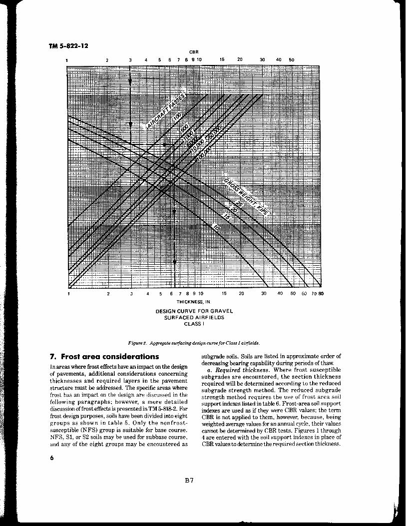
5. Design of aggregate surfaced airfields
The thickness design of aggregate surfaced airfields is similar to the design of flexible pavement airfields as contained in TM 5-825-2. This procedure involves assigning a class to the airfield based upon the aircraft controlling the design. Having selected the class of airfield, the design is accomplished using figures 2 through4.
a. Classes of airfields. There are four classes of Army airfields. These are Classes I-IV, although only Classes 1-111 are considered candidates for aggregate surfacing. Each class of airfield is designed for a standard loading condition and pass level as defined in TM 5-803-4. Where necessary, airfields may be designed for loads and pass levels other than the standard, and the criteria herein provide thicknesses for varying pass and load levels.
b. Traffic areas. Army airfields are divided into traffic areas for design purposes. Type B traffic areas consist of taxiways, the first 1,000 feet of runway ends, and aprons. Type C traffic areas are the interior portions of the runway (between the 1,000 foot runway ends).
c. Thickness criteria (nonfrost areas). Thickness requirements for aggregate surfaced airfields are determined from figures 2 through 4 for types B and C traffic areas. Thicknesses for type B areas are determined directly from the curves, and type C traffic areas are designed using 75 percent of the load used to design type B traffic areas. The minimum thickness requirement for all cases will be 4 inches. The figure for the appropriate airfield class will be entered with the subgrade CBR to determine the thickness required for a given load and pass level. The thickness determined from the figure may be constructed of compacted granular fill for the total depth over the natural subgrade or in a layered system of granular fill and compacted subgrade for the same total depth. The layered section should be checked to ensure that an adequate thickness of material is used to protect the underlying layer based upon the CBR of the underlying layer. The granular fill may consist of base and subbase material provided the top 6 inches meet the gradation requirements of paragraph 8.
6. Design CBR for select materials and subbases
Design CBR values and materials requirements for select materials and subbases are to be selected in accordance with TM 5-825-2 except as modified in table 4.
5
TM 5-822-12 CBR
2 3 4 5 6 7 B 9 10 15 20 30 40 50
2 3 4 5 6 7 B 9 10 15 20 30 40 so 60 70 80
THICKNESS, IN.
DESIGN CURVE FOR GRAVEL SURFACED AIRFIELDS
CLASS I
Figure 2. Aggregate su1facing design curoefor Class I ai!fields.
7. Frost area considerations In areas where frost effects have an impact on the design of pavements, additional considerations concerning thicknesses and required layers in the pavement structure must be addressed. The specific areas where frost has an impact on the design are discussed in the following paragraphs; however, a more detailed discussion of frost effects is presented in TM 5-818-2. For frost design purposes, soils have been divided into eight groups as shown in table 5. Only the nonfrostsusceptible (NFS) group is suitable for base course. NFS, Sl, or S2 soils may be used for subbase course, and any of the eight groups may be encountered as
6
B7
subgrade soils. Soils are listed in approximate order of decreasing bearing capability during periods of thaw.
a. Required thickness. Where frost susceptible subgrades are encountered, the section thickness required will be determined according to the reduced subgrade strength method. The reduced subgrade strength method requires the use of frost area soil support indexes listed in table 6. Frost-area soil support indexes are used as if they were CBR values; the term CBR is not applied to them, however, because, being weighted average values for an annual cycle, their values cannot be determined by CBR tests. Figures 1 through 4 are entered with the soil support indexes in place of CBR values to determine the required section thickness.

TM 5-822-12 CBR
2 3 4 5 6 7 B 9 10 15 20 30 40 50
2 3 4 5 6 7 8 9 10
THICKNESS. IN.
15 20 30 40 50 60 70 80
DESIGN CURVE FOR GRAVEL SURFACED AIRFIELDS
CLASS II
Figure S. Aggregate surfacing design curve for Class I I airfields.
b. Required layers in pavement section. When frost is a consideration, it is recommended that the pavement section consist of a series of layers that will ensure the stability of the system, particularly during thaw periods. The layered system in the aggregate fill may consist of a wearing surface of fine crushed stone, a coarse-graded base course, and/or a well-graded subbase of sand or gravelly sand. To ensure the stability of the wearing surface, the width of the base course and subbase should exceed the final desired surface width by a minimum of 1 foot on each side.
c. Wearing surface. The wearing surface contains fines to provide stability in the aggregate surface. The presence of fines helps the layer's compaction
BS
characteristics and helps to provide a relatively smooth riding surface.
d. Base course. The coarse-graded base course is important in providing drainage of the granular fill. It is also important that this material be nonfrostsusceptible so that it retains its strength during spring thaw periods.
e. Subbase. The well-graded sand subbase is used for additional bearing capacity over the frost-susceptible subgrade and as a filter layer between the coarse-graded base course and the subgrade to prevent the migration of the subgrade into the voids in the coarser material during periods of reduced subgrade strength. The material must therefore meet standard filter criteria.
7

TM 5-822-12
CBR
2 3 4 5 6 7 8 9 10 15 20 30 40 50
--- I
-· --- ,_
I . w -" ;w ~
I '·- ·~ I
._ -~
• II
I I
• I --,1.. - -
"' - : ..... ,:----
~ .~ ~·11 -~~~ ...._
- --~"t----t-·:
- ----j-____::~
2 3 4 5 6 7 8910 15 20 30 40 50
THICKNESS, IN.
DESIGN CURVES FOR GRAVEL SURFACED AIRFIELDS
CLASS 111
Figure 4. Aggregate surfacing design curve for Class I II airfields.
The sand subbase must be either nonfrost-susceptible or oflow frost susceptibility (SI or 82). The filter layer may or may not be necessary depending upon the type of subgrade material. If the subgrade consists principally of gravel or sand, the filter layer may not be necessary and may be replaced by additional base course if the gradation of the base course is such that it meets filter criteria. However, for finer grained soils, the filter layer will be necessary. If a geotextile is used, the sand subbase/filter layer may be omitted as the fabric will be placed directly on the subgrade and will act as a filter.
8
B9
f Compaction. The subgrade should be compacted to provide uniformity of conditions and a firm working platform for placement and compaction of subbase. Compaction of subgrade will not change its frost-area soil support index, however, because frost action will cause the subgrade to revert to a weaker state. Hence, in frost areas, the compacted subgrade will not be considered part of the layered system of the road or airfield which should be comprised of only the wearing, base, and subbase courses.
g. Thickrwss of base caurse and filter layer. Relative thicknesses of the base course and filter layer are

Material
Sub base Sub base Sub base Select
material
Tabw 4. Maximum permissibw values for subbases and select materials.
Maximum Permissible Value
Gradation Requirements
Percent Passing
Maximum No. No. Design Size 10 200 Liquid Plasticity CBR inch Sieve Sieve Limit* Index• --------
50 2 50 15 25 5 40 2 80 15 25 5 30 2 100 15 25 5
20 3 35 12
*Detenninations of these values will be made in accordance with ASTMD4318.
variable, and should be based on the required cover and economic considerations.
h. AUernaf-e design. The reduced subgrade strength design procedure provides the thickness of soil required above a frost-susceptible subgrade to minimize frost heave. To provide a more economical design, a frost susceptible select material or subbase may be used as a part of the total thickness above the frost-susceptible subgrade. However, the thickness above the select material or subbase must be determined by using the FASS! of the select or subbase material. Where frosts uscepti ble soils are used as select materials or subbases, they must meet the requirements of current specifications except that the restriction on the allowable percent finer than 0.02 mm is waived.
8. Surface course requirements The requirements for the various materials to be used in the construction of aggregate surfaced roads and airfields are dependent upon whether or not frost is a consideration in the design.
a. Nonfrost areas. The material used for gravelsurfaced roads and airfields should be sufficiently cohesive to resist abrasive action. It should have a liquid limit no greater than 35 and a plasticity index of 4 to 9. It should also be graded for maximum density and minimum volume of voids in order to enhance optimum moisture retention while resisting excessive water intrusion. The gradation, therefore, should consist of the optimum combination of coarse and fine aggregates that will ensure minimum void ratios and maximum density. Such a material will then exhibit cohesive strength as well as intergranular shear strength. Recommended gradations are as shown in table 7. If the fine fraction of the material does not meet plasticity characteristics, modification by addition of chemicals might be required. Chloride products can, in some cases, enhance moisture retention, and lime can be used to reduce excessive plasticity.
BlO
TM 5-822-12
b. Frost are.as. As previously stated, where frost is a consideration in the design of roads and airfields, a layered system should be used. The percentage of fines should be restricted in all the layers to facilitate drainage and reduce the loss of stability and strength during thaw periods. Gradation numbers 3 and 4 shown in table 7 should be used with caution since they may be unstable in a freeze-thaw environment.
9. Compadion requirements Compaction requirements for the subgrade and granular layers are expressed as a percent of maximum CE 55 density as determined by using MIL-STD-621 Test Method 100. For the granular layers, the material will be compacted to 100 percent of the maximum CE 55 density. Select materials and subgrades in fills shall have densities equal to or greater than the values shown in tables 8 and 9 for roads and table 10 for airfields except that fills will be placed at no less than 95 percent compaction for cohesionless soils (PI~ 5; LL~ 25) or 90 percent compaction for cohesive soils (Pl > 5; LL > 25). Subgrades in cuts shall have densities equal to or greater than the values shown in tables 8 through 10. Subgrades occurring in cut sections will be either compacted from the surface to meet the densities shown in tables 8 through 10, removed and replaced before applying the requirements for fills, or covered with sufficient material so that the uncompacted subgrade will be at a depth where the in-place densities are satisfactory. The depths shown in tables 8 through 10 are measured from the surface of the aggregate road or airfield and not the surface of the subgrade.
10. Drainage requirements Adequate surface drainage should be provided in order to minimize moisture damage. Expeditious removal of surface water reduces the potential for absorption and ensures more consistent strength and reduced maintenance. Drainage, however, must be provided in a manner to preclude damage to the aggregate surfaced road or airfield through erosion of fines or erosion of the entire surface layer. Also, care must be taken to ensure that the change in the overall drainage regime as a result of construction can be accommodated by the surrounding topography without damage to the environment or to the newly constructed road or airfield.
a. The surface geometry of a road or airfield should be designed so that drainage is provided at all points. Depending upon the surrounding terrain, surface drainage of the roadway can be achieved by a continual cross slope or by a series of two or more interconnecting cross slopes. The entire area should consist of one or more cross slopes having a gradient that meet the requirements of TM 5-820-1andTM5-820-4. Judgement will be required to arrange the cross slopes in a manner to remove water from the road or airfield at the nearest
9

TM 5-822-12
10
Table 5. Frost design soil classification.
Percentage Finer Than Typical Soil Types
Frost 0.02 mm Under Unified Soil
Group Kind of Soil by Weight Classification System
\\t~'k \a) \;itO.~~h ()-\.. ') G~, GP
Crushed stone Crushed rock
(b) Sands 0-3 SW, SP
PFS** (a) Gravels 1.5-3 GW, GP Crushed stone Crushed rock
(b) Sands 3-10 SW, SP
Sl Gravelly soils 3-6 GW, GP, GW-GM, GP-GM
S2 Sandy soils 3-6 SW, SP, SW-SM, SP-SM
Fl Gravelly soils 6 to 10 GM, GW-GM, GP-GM
F2 (a) Gravelly soils 10 to 20 GM, GW-GM, GP-GM (b) Sands 6 to 15 SM, SW-SM, SP-SM
F3 (a) Gravelly soils Over 20 GM, GC (b) Sands, except Over 15 SM, SC
very fine silty sands
(c) Clays, PI > 12 CL, CH
F4 (a) All silts ML, MH
(b) Very fine silty Over 15 SM sands
(c) Clays, PI < 12 CL, CL-ML (d) Varved clays CL and ML
and other fine- CL, ML, and SM
grained banded CL, CH, and ML sediments CL, CH, ML and SM
*Nonfrost-susceptible. **Possibly frost-susceptible, but requires laboratory test to
determine frost design soil classification.
Table 6. Frost-area soil support indexes ofsubgrade soils.
Frost Group of Subgrade Soils
Fl and Sl F2 and S2 F3and F4
Frost Area Soil Support Index
9.0 6.5 3.5
Bll
possible points while taking advantage of the natural surface geometry to the greatest extent possible.
b. Adequate drainage must be provided outside the road or airfield area to accommodate maximum possible drainage flow from the road or airfield. Ditches and culverts will be provided for this purpose. Culverts should be used sparingly and only in areas where adequate cover of granular fill is provided over the culvert. Additionally, adjacent areas and their drainage

TM 5-822-12
Table 7. Gradation for O{Jgregate surface courses. ~I "' ,.._ N ,.._ N N
Sieve Designation No. 1 No. 2 No.3 No.4 --- ------
25.0mm 1 in. 100 100 100 100
9.5mm 3/8in. 50-85 60-100 °'I
l/"\ 0 l/"\ 0 l/"\ 4.7mm No.4 35--65 50-85 55-100 70--100 ...... ...... N N
>< 2.00mm No. 10 25--50 40--70 40--100 55-100 cu
0.425mm No.40 15-30 24-45 20--50 30--70 "O i::
0.075mm No. 200 8-15 8-15 8-15 8-15 ......
Note: The percent by weight finer than 0.02 mm shall not exceed i::
<X) I l/"\ °' (""\ <X) N ...... N
3 percent. ..... (I)
cu A
provisions should be evaluated to determine if rerouting "O
is needed to prevent water from other areas flowing cu ..... 1
-<t <X) N "' 0 4J ...... N
across the road or airfield. <IS ()
c. Drainage is a critical factor in aggregate surface ..... ~ "O
road or airfield design, construction, and maintenance. ·~ i:: ...... Therefore, drainage should be considered prior to "' "'I
-<t ,.._ l/"\ <X)
.::: "" ...... ......
construction, and when necessary, serve as a basis for ., 0 "' .... ~
site selection. c " ,-, .; (I) ..., cu
11. Maintenance requirements <::l !2 .s::: l/"\I -<t ,.._ 0 (""\ "' ... () ......
The two primary causes of deterioration of aggregate ~ i:: .....
surfaced roads requiring frequent maintenance are the !:! i:: "' environment and traffic. Rain or water flow will wash 1' .....
~
fines from the aggregate surface and reduce cohesion, ·;;; i::
-<t I (""\ '° °' N -<t
"'" while traffic action causes displacement of surface "' 0 ...... ... ..... "' materials. Maintenance should be performed at least ~
4J ()
" <IS every 6 months and more frequently if required. The "' "'- a frequency of maintenance will be high for the first few "' c 0
years of use but will decrease over time to a constant c..i u <"\I (""\ l/"\ <X) 0 (""\
value. The majority of the maintenance will consist of aO .... "' 0 -0
periodic grading to remove the ruts and potholes that "' .s::: !'..
will inevitably be created by the environment and traffic ....
and to replace fines. Occasionally during the lifetime of cu A NI (""\ l/"\ ,.._
°' the road or airfield, the surface layer may have to be scarified, additional aggregate added to increase the thickness back to that originally required, and the wearing surface recompacted to the specified density.
...... 1 N -<t '° ,.._
°' 12. Dust control
a. Objective. The primary objective of a dust palliative is to prevent soil particles from becoming
~ airborne as a result of wind or traffic. Where dust 4J
palliatives are considered for traffic areas, they must i:: cu 0 l/"\ 0 l/"\ 0
withstand the abrasion of the wheels or tracks. An () 0 °' °' CXl CXl
"" ......
important factor limiting the applicability of the dust cu 11.
palliative in traffic areas is the extent of surface rutting or abrasion that will occur under traffic. Some palliatives will tolerate deformations better than others, but normally ruts in excess of 112 inch will result in the virtual destruction of any thin layer or shallow-depth penetration dust palliative treatment. The abrasive action of tank tracks may be too severe for use of some singled out as being the most universally acceptable for
dust palliatives in a traffic area. all problem situations that may be encountered.
b. A wide selection of materials for dust control is However, several materials have been recommended for
available to the engineer. No one choice, however, can be use and are discussed in TM 5-830-3.
11
Bl2

..
ttl I-' w
I I I ~ ~ ~ $'; ~ ·~3~g
Ul'O.,., IJq ~ ~ e:.. ~ (""t'- (""t'- C/l
~~~ c <'tl"'oo-0... cc~ '"' O" 'O "' ., ~ "':l 0...
~ "' c.:> <'tl ~ ~ :-' II o... II 01 .,
0 0 00 '"' . t"" :>;""
~ 3 "' "' '"'" ., <'tl
5· ::i. IJq e:.. (/l §. c ., '"'" ~ ::r (",) '"Cl <'tl .......
Percent Compaction
100
95
90
85
Airfield Tlpe
Class I
Class II
Class III
1
4
7
10
13
Traffic Area
B
c
B
c
B
c
Table 9. Compaction requirements for roads, colwsionless soils.
Depth of Compaction (in inches) for Indicated Design Index 2 3 4 5 6 7 8 9
5
8
12
16
100
4
3
5
4
9
7
5
10
14
18
6
11
16
21
7
12
18
23
7
14
20
26
Table JO. Compaction requirements for airfields.
8
15
22
29
9
17
24
31
Depth Below Pavement Surface, in. Cohesive Soils, percent Cohesionless
95 90 85 80 105 !QQ
6 8 10 12 2 6
5 7 9 10 1 5
8 12 15 19 2 8
7 10 13 16 2 7
15 21 27 34 4 15
12 17 22 29 3 12
Soils, 95
10
8
14
12
25
21
10
19
28
35
percent 90
13
11
21
17
37
31
10
11
21
30
38
85
16
14
26
23
48
41
; UI I e I .. ..,

-Coarse graded crushed rock base course = 80. -Clean sand subbase = 15.
Anti.cipat,ed traffic. ---40 passes per day of 60-ton tracked vehicles.
Calculati.ons: a. From paragraph 4.d, select the traffic category for
a 120,000-pounds tracked vehicle as Category VIL b. The design index is then determined from table 3 to
be 10 for 40 passes per day and Category VII traffic. c. The required thickness of the tank trail is deter
mined from figure 1. The following sections would be adequate if the natural subgrade has the required in-place density.
17 inches crushed rock
Natural subgrade CBR = 5
7 inches crushed rock
10 inches sand sub base CBR = 15
Natural subgrade CBR = 5
d. Where the subgrade is compacted to a CBR of 8, the following sections would be satisfactory:
12 inches crushed rock
5 inches compacted subgrade CBR = 8
Natural subgrade CBR = 5
7 inches crushed rock
5 inches sand subbase CBR = 15
5 inches compacted subgrade CBR =8
Natural subgrade CBR = 5
e. In areas where frost is not a factor in the design of roads, the sections shown above are adequate, and the most economical should be used. The granular material should conform to the material requirements for nonfrost areas previously discussed. If available, subbase materials other than the clean sand may be used for adjusting the sections.
f. Determine the surface geometry of the tank trail in a severely cold area where subgrade freezing is predicted.
g. In areas where frost is a consideration, the tank trail should consist of the following layers:
-A wearing surface of fine-graded crushed rock. -A base course of coarse-graded crushed rock. -A subbase of well-graded sand, frost group soils
Fl and F2, or geotextile. As previously stated, the function of the last layer as a filter layer is not always required, depending upon the subgrade material. In this case the subgrade is a CL; therefore, it is required. According to table 6, the frostarea soil support index for an F3 subgrade soil is 3.5. With the exception of the wearing surface layer which will vary between 4 and 6 inches, the other layers are \·aried based on economic factors. However. the required
B14
TM 5-822-12
thickness of cover over the various layers must be satisfied. Also, the minimum thickness of each layer should be4 inches.
h. Possible alternatives for the tank trail section based on frost considerations might be:
(1) Using sand subbase. From figure 1 using a frost-area soil support index of3.5 and a design index of 10, the total thickness required above the subgrade equals 21.0 inches. Also from figure 1, the minimum required cover over the NFS, Sl, or 82 sand subbase ( CBR = 15) is 7.0 inches. Using a minimum layer thickness of 4 inches in the wearing surface and the course graded base course, the actual cover required will be 8 inches. Therefore, the section might be:
4 inches fine-graded stone
4 inches coarse-graded crushed stone
13 inches well-graded sand subbase <CBR = 15)
Subgrade
(2) An alternative section might be to construct the wearing course and subbase to a minimum thickness of 4 inches.
4 inches fin&'graded stone
13 inches coarse-graded crushed stone
4 inches well-graded sand subbase
Subgrade
(3) Using Fl and F2 soils. As previously stated. frost group soils Fl and F2 may be used in the lower part of the granular material over F3 and F4 subgrade soils. The thickness of F2 base material should not exceed the difference between the thickness required over F3 and the thickness required over an F2 subgrade. The minimum required cover over Fl soils is 11 inches, over F2 soils is 14 inches, and over F3 soils is 21 inches. Using a minimum layer thickness of 4 inches, the following section may be used:
4 inches fine-graded stone
7 inches coarse-graded crushed stone
4 inches frost group soil F 1
6 inches frost group soil F2
Subgrade - F3
For economy, based on material availability, these sections may be altered as long as a higher-quality material is used above a lesser-quality material. For example. crushed stone could be substituted for the Fl soil.
13

TM 5-822-12
( 4) Using geotextiles. Either of the designs shown above could be used by deducting 6 inches of well-graded sand subbase and replacing it with a geotextile. The total thickness above the geotextile must be a minimum of 15 inches. Alternative designs using a geotextile might be:
4 inches fine-graded stone
11 inches coarse-graded crushed stone
--------- geotextile Subgrade
or:
7 inches fine-graded stone
8 inches well-graded sand
--------- geotextile Subgrade
Notes: -All layer depths should be rounded up to the next
full inch for construction purposes. -The granular layers should be compacted to 100 per
cent CE 55 maximum density. -The subgrade should be compacted to the density
required by table 8. -The material should meet the gradation require
ments shown herein. -The frost group soils Fl and F2 used as base and
subbase materials should meet the requirements in the appropriate guide specifications.
-As previously stated, after all possible design sections are determined, the final section used for the tank trail should be determined on the basis of an economic analysis.
14. Design Example No. 2. Assume the following conditions:
CBR values. -Natural subgrade = 4 (SM - silty sand
material, frost group F2). -Compacted subgrade = 8. -Fine-graded crushed rock wearing surface = 80. -Course-graded crushed rock base course = 80. -Clean sand subbase = 15.
Projected traffic. -2,500 operations per day of Category IV traffic.
C alculatWris: a. Determine the required thickness. From table 1
determine the road to be a Class D road. From table 3, select a design index = 5. From the design curves (figure 1) the required thickness above the natural subgrade with a CBR of 4 is 11.5 inches (round to next full inch of 12); the required cover over the compacted subgrade (CBR = 8) is 7 inches. Therefore, the hardstand might have the following cross sections:
14
B15
12.0 inches crushed 4 inches crushed 7 inches crushed rock rock rock
8.0 inches sand Compacted subbase subgrade CBR = 8
Subgrade CBR = 4 Subgrade CBR = 4
b. Determine the cross section in a severely cold area where subgrade freezing is predicted.
(1) Only the wearing surface and base course layers will apply in this section. The sand subbase is not required because the subgrade is not cohesive. The filter fabric will not be used because the subgrade soil is an F2 material and the use of this fabric is restricted to F3 and F4 subgrade soils.
(2) In this case the natural subgrade CBR of 4 is less than the frost-area soil support index and will govern the design. The total thickness required above a subgrade CBR = 4is12.0 inches.
(3) Therefore, the cross section for this condition will be:
4 inches fine-graded stone
8. 0 inches coarse-graded crushed stone
Subgrade CBR = 4
c. Based on economic considerations, alternative sections may be developed using frost group soils Sl, S2, and Fl with lower portion of the base material. An example using Fl soils is as follows:
7. 0 inches fine-graded stone
5 inches frost group soil Fl
Subgrade CBR = 4
1 S. Design Example No. 3. Assume the following conditions:
Design is for Army Class Ill airfield. Traffic protection = 10,000 passes ofC-130 aircraft. Design gross weighl = 135 kips. CBRvalues.
-Subgrade = 6 -Crushed stone = 80
Enter figure 4 with the subgrade CBR of 6, the 135 kip gross weight and 10,000 passes, and read the thickness required above the 6 CBR of 13.5 inches which when rounded to the next full inch will be 14.0 inches. The section therefore would be:
14.0 inches of crushed stone
Subgrade CBR = 6

TM 5-822-12
APPENDIX A
REFERENCES
Government Publications De'f)<Lrtment of Defense
MIL-STD-621A, Notices 1, 2
Test Method for Pavement Subgrade, Subbase, and Base-Course Materials
Departments of the Army, Navy, and Air Force TM 5-803-4 Planning of Army
TM5-818-2 Aviation Facilities
Pavement Design of Seasonal Frost Areas
TM 5-820-1/ AFM 88- Surface Drainage 5, Chap. 1
TM 5-820-4/ AFM 88-5, Chap. 4
TM 5-822-2/ AFM 88-7, Chap. 5
Facilities for Airfields and Heliports
Drainage for Areas Other Than Airfields
General Provisions and Geometric Design for Roads, Streets, Walks, and Open Storage Areas
B16
TM 5-822-5/ AFM 88-7, Chap. 3
TM 5-825-2/ AFM 86-6, Chap. 2/ NAVFAC DM 21.3
TM5-830-3
Flexible Pavements for Roads, Streets, Walks and Open Storage Areas
Flexible Pavement Design for Airfields
Dust Control for Roads, Airfields, and Adjacent Areas
Nongovernment Publications American Soci.ety for Testing and Materials (ASTM): 1916 Race Street, Philadelphia, PA 19103
D 4318-83 Test Method for Liquid Limit, Plastic Limit, and Plasticity Index of Soils
A-1

TM 5-822-12
The proponent agency of this publication is the Office of the Chief of Engineers, United States Army. Users are invited to send comments and suggested improvements on DA Form 2028 (Recommended Changes to Publications and Blank Forms) to HQUSACE (CEMP-ET), WASH, D.C. 20314-1000.
By Order of the Secretary of the Army:
Official: THOMAS F. SIKORA
Brigadier General, United States Army The Adjutant General
CARLE. VUONO General, United States Army
C hi.ef of Staff
Distribution: To be distributed in accordance with DA Form 12-34E, Block 4111, requirements for TM 5-822-12.
Bl7

a: 0 ... u < ... z !! ... ... ;;: w a: Q
< 0 .J
i.•o
l.lO
1.20
1.10
1.00
0.90
0.10
0.70
0.<40
0.30
0.20
0.10
COVl:RAGES
LOAD REPITITION FACTOR VERSUS COVERAGES

Waterways Experiment Station Cataloglng-in-Publlcation Data
Webster, Steve L. Description and application of dual mass dynamic cone penetrometer I
by Steve L. Webster, Richard H. Grau, Thomas P. Williams; prepared for Department of the Army, U.S. Army Corps of Engineers.
50 p. : ill. ; 28 cm. -- (Instruction report ; GL-92-3) Includes bibliographic references. 1. Penetrometer -- Testing. 2. Soil penetration test. 3. Pavements -
Foundations -- Testing. 4. Runways (Aeronautics) -- Testing. I. Title. II. Grau, Richard H. Ill. Williams Thomas P. IV. United States. Army. Corps of Engineers. V. U.S. Army Engineer Waterways Experiment Station. VI. Series: Instruction report (U.S. Army Engineer Waterways Experiment Station) ; GL-92-3 TA? W34i no.GL-92-3


![This article was downloaded by:[Price, Sarah L.]](https://img.dokumen.tips/doc/110x75/61d6c468f4773d6f070bbfd9/this-article-was-downloaded-byprice-sarah-l.jpg)