Embed Size (px)
Citation preview

This document downloaded from vulcanhammer.net vulcanhammer.info
Chet Aero Marine
Don’t forget to visit our companion site http://www.vulcanhammer.org
Use subject to the terms and conditions of the respective websites.

ENCE 4610ENCE 4610Foundation Analysis and DesignFoundation Analysis and Design
Lecture 2Shallow Foundations:
OverviewBasic Bearing Capacity Equations

Types of Shallow Types of Shallow FoundationsFoundations
Shallow foundations are usually placed within a depth D beneath the ground surface less than the minimum width B of the foundationShallow foundations consist of:
Spread and continuous footingsSquare, Rectangular or Circular FootingsContinuous footingsRing FoundationsStrap Footings
Wall footingsMats or Rafts

FootingsA finite spread footing is a shallow foundation that transmits loads and has an aspect ratio of 1 < L/B < 10A continuous spread footing is an “infinite”footing where L/B > 10 and the effects of L are ignored

Dimension and Rubble Dimension and Rubble Stone FootingsStone Footings
Before 1800, most all footings were unreinforced masonry, as shown
Dimension stone footingsRubble stone footings
Satisfactory for lighter structures, they were too heavy for the larger structures of the 19th century
Steel Grillage FootingsSteel Grillage Footings
Used first with the Montauk Block Building in Chicago (1882). First foundation type specifically designed for flexure.
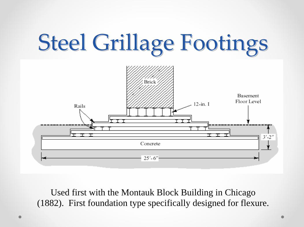
Typical Concrete Typical Concrete FootingFooting

Methods of Construction of Methods of Construction of
Concrete FootingsConcrete Footings
Formed footing
Once form is made, before concrete is poured either anchor bolts or dowels are placed to enable connection of the foundation with the building.

Mat FoundationsMat FoundationsA mat is continuous in two directions capable of supporting multiple columns, wall or floor loads. It has dimensions from 20 to 80 ft or more for houses and hundreds of feet for large structures such as multi-story hospitals and some warehousesRibbed mats, consisting of stiffening beams placed below a flat slab are useful in unstable soils such as expansive, collapsible or soft materials where differential movements can be significant (exceeding 0.5 inch).

Conditions for Mat Conditions for Mat FoundationsFoundations
Structural loads require large area to spread the loadSoil is erratic and prone to differential settlementsStructural loads are erraticUnevenly distributed lateral loadsUplift loads are larger than spread footings can accommodate; weight of the mat is a factor hereMat foundations are easier to waterproof
Example: Chase Tower, Houston, TX
Mat foundation is 3 metres thick and bottomed at 19.2 m below street level

Distribution of Bearing Distribution of Bearing PressurePressure
Spread footings are nearly rigid; effects of foundation/soil flexibility usually ignoredMat foundations are more flexible; flexibility an important factor
Distribution of bearing pressure depends on
Eccentricity, if any, of applied loadMagnitude of the applied moment, if anyStructural rigidity of the foundationStress-strain properties of the soilRoughness of the bottom of the foundation

Bearing Pressure DistributionBearing Pressure DistributionConcentric LoadsConcentric Loads
Flexible foundation on clay
Flexible Foundation on Sand
Rigid foundation on clay
Rigid Foundation on Sand
Simplified Distribution

Types of Bearing Capacity
• Traditionally, bearing capacity has been classified as follows:– General Shear– Local Shear– Punching Shear– Which one takes place depends
upon consistency or density of soil, which decreases from general to local to punching
• For our purposes, we will only consider general shear; other modes are better predicted using settlement analysis

Plasticity: Lower and Upper Bound Solutions
• Review of Concept– Lower Bound: The true failure
load is larger than the load corresponding to an equilibrium system. The system has failed in at least one place.
– Upper Bound: The true failure load is smaller than the load corresponding to a mechanism, if that load is determined using the virtual work principle. The system has failed “in general.”
• The idea is that the true solution is somewhere between the two
• We saw this when we went through unsupported cuts in purely cohesive soils
• In principle, only applicable to purely cohesive soils without friction, due to volume expansion considerations
• We will begin by considering strip (infinite or continuous) foundations only) in cohesive soils

Lower Bound SolutionBy direct application and Mohr's Circle
By theory of elasticity
The more realistic lower bound
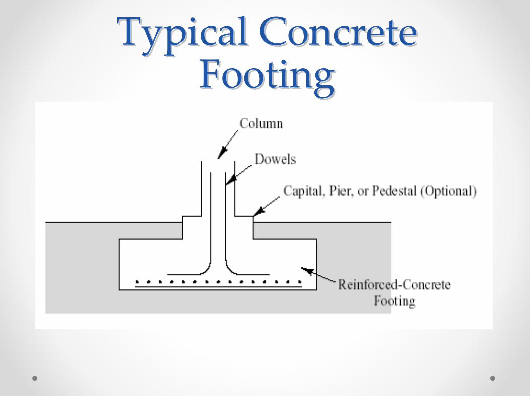
Upper Bound Limit Equilibrium MethodUpper Bound Limit Equilibrium Method
(Circular Failure Surface, Cohesive Soil)(Circular Failure Surface, Cohesive Soil)0
22 0 =BBbσBπcBbBBbq=M ultp ×−×−×∑
Assume: No soil strength due to internal friction (cohesive soil,) shear strength above foundation base neglectedWe add the effect of the weight of the soil (effective stress) acting on the top of the right side of the circle against rotation.
0cult
c
0ult
σ+cN=qπ=N
σ+πc=q6.282
2≈

More Realistic Upper Bound Case
So the solution is bounded by

Application of Circular Failure Surface (Upper Bound Condition)
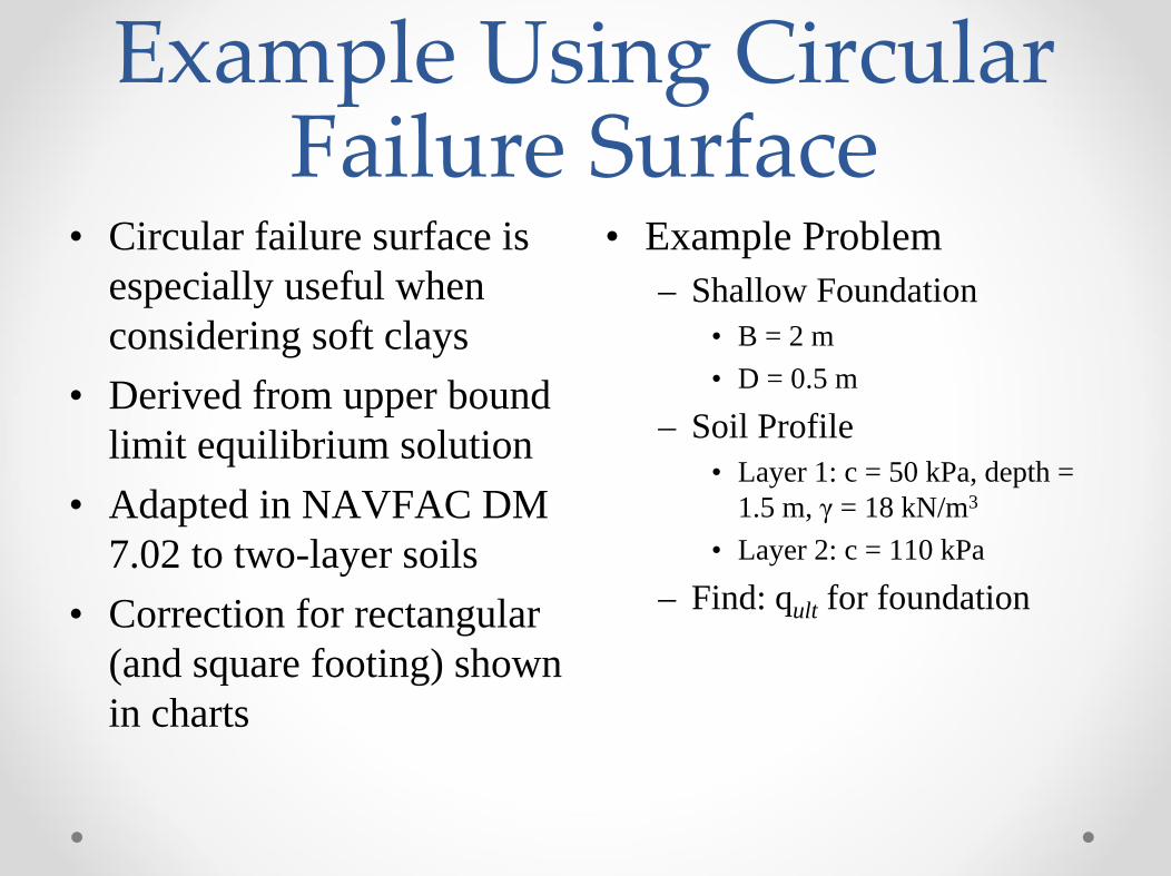
Example Using Circular Failure Surface
• Circular failure surface is especially useful when considering soft clays
• Derived from upper bound limit equilibrium solution
• Adapted in NAVFAC DM 7.02 to two-layer soils
• Correction for rectangular (and square footing) shown in charts
• Example Problem– Shallow Foundation
• B = 2 m• D = 0.5 m
– Soil Profile• Layer 1: c = 50 kPa, depth =
1.5 m, γ = 18 kN/m3
• Layer 2: c = 110 kPa
– Find: qult for foundation
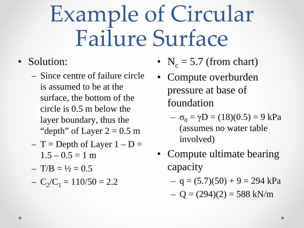
Example of Circular Failure Surface
• Solution:– Since centre of failure circle
is assumed to be at the surface, the bottom of the circle is 0.5 m below the layer boundary, thus the “depth” of Layer 2 = 0.5 m
– T = Depth of Layer 1 – D = 1.5 – 0.5 = 1 m
– T/B = ½ = 0.5– C2/C1 = 110/50 = 2.2
• Nc = 5.7 (from chart)• Compute overburden
pressure at base of foundation– σ0 = γD = (18)(0.5) = 9 kPa
(assumes no water table involved)
• Compute ultimate bearing capacity– q = (5.7)(50) + 9 = 294 kPa– Q = (294)(2) = 588 kN/m

Development of PrandtlBearing Capacity Theory
Application of limit equilibrium methods first done by Prandtl on the punching of thick masses of metal (materials with no internal frictional effects)Prandtl's methods first adapted by Terzaghi to bearing capacity failure of shallow foundations (specifically, he added the effects of frictional materials)Vesić and others (Meyerhof, Brinch Hansen, etc.) improved on Terzaghi'soriginal theory and added other factors for a more complete analysis
Note the three zones, the foundation fails along the lower boundary of these zones
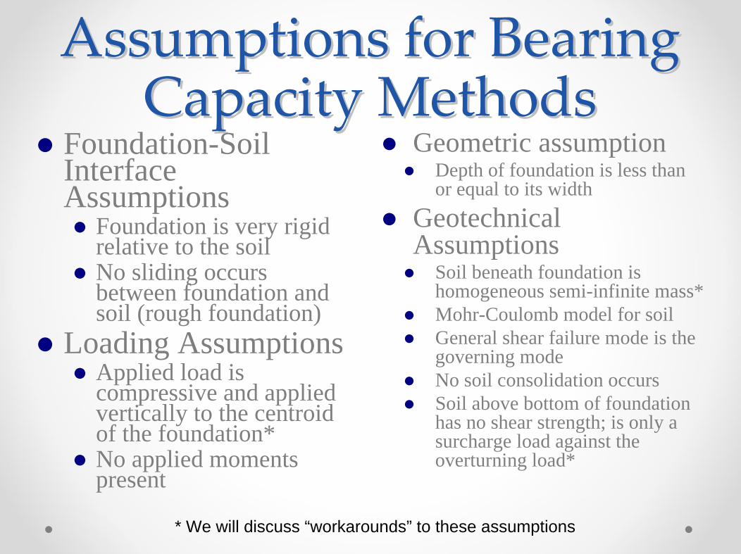
Assumptions for Bearing Assumptions for Bearing Capacity MethodsCapacity Methods
Geometric assumptionDepth of foundation is less than or equal to its width
Geotechnical Assumptions
Soil beneath foundation is homogeneous semi-infinite mass*Mohr-Coulomb model for soilGeneral shear failure mode is the governing mode No soil consolidation occursSoil above bottom of foundation has no shear strength; is only a surcharge load against the overturning load*
Foundation-Soil Interface Assumptions
Foundation is very rigid relative to the soilNo sliding occurs between foundation and soil (rough foundation)
Loading AssumptionsApplied load is compressive and applied vertically to the centroidof the foundation*No applied moments present
* We will discuss “workarounds” to these assumptions
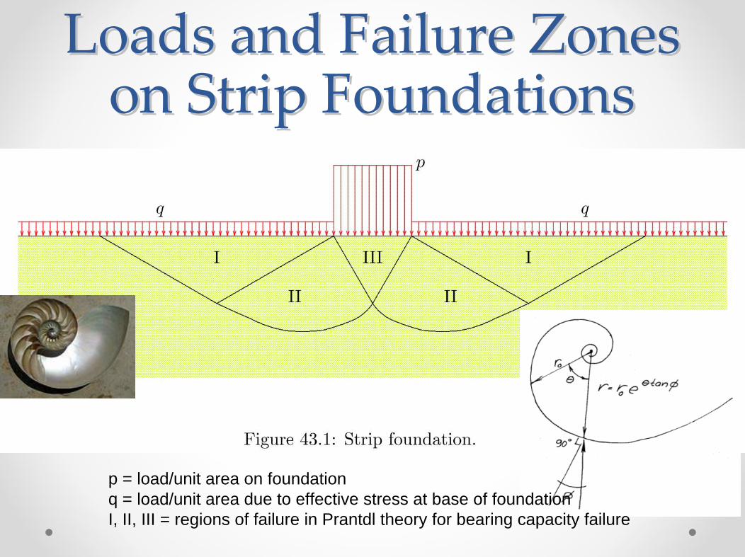
Loads and Failure Zones Loads and Failure Zones on Strip Foundationson Strip Foundations
p = load/unit area on foundationq = load/unit area due to effective stress at base of foundationI, II, III = regions of failure in Prantdl theory for bearing capacity failure

Basic Equation of Bearing Capacity
Basic bearing capacity equation:
p = unit pressure on foundationq = effective stress at base of foundationsγ = (average) soil unit weight under foundationB = basic width of foundationsStrictly speaking, applicable to continuous foundations only
Bearing Capacity Factors
Several variations on the basic theory existValues of Nc, Nqmostly the same:
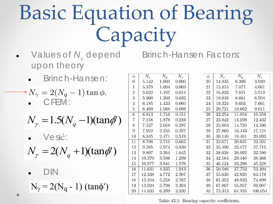
Basic Equation of Bearing Capacity
Values of Nγ depend upon theory
Brinch-Hansen:
CFEM:
Vesić:
DIN
Brinch-Hansen Factors:

Bearing Capacity Example
Load is concentric GivenContinuous foundation as shownGroundwater table is “very deep”Ignore effects of floor loading
FindUnit bearing capacity and load P

Bearing Capacity Example
Bearing capacity factors as shownDetermine effective stress at base of foundation
q = (2)(121) = 242 psfDetermine average unit weight of soil in failure zone
γ‘ = 121 pcfDetermine basic size of foundation
B = 3.25’

Bearing Capacity Example
Substitute and Solve as shown:
Compute ultimate capacityPult = p * APult = (12.924)(3.25)(1)Pult = 42 kips/ft
Keep in mind that the design load supported by the foundation includes the weight of the footing, which is part of the dead load

Questions?


![Module 4 : Design of Shallow Foundations Lecture 18 ... · Lecture 18 : Structural designs of column and footing [ Section18.3 : Design of Strap Footing ] Objectives In this section](https://img.dokumen.tips/doc/110x75/5e8a8d4d85e38b02b4098db3/module-4-design-of-shallow-foundations-lecture-18-lecture-18-structural.jpg)