Embed Size (px)
Citation preview
Bureau of StafTdaras
' 2 1 7967
BUILDING SCIENCE SERIES
Thermal-Shock
Resistance
for Built-Up
Membranes
^ B DEPARTMENT OF COMMERCE^ /I/ National Bureau of Standards
Announcing — The Building Science Series
The "Building Science Series" disseminates technical information developed at the
Bureau on building materials, components, systems, and whole structures. The series
presents research results, test methods, and performance criteria related to the structural
and environmental functions and the durability and safety characteristics of building
elements and systems.
These publications, similar in style and content to the NBS Building Materials and
Structure Reports (1938-59), are directed toward the manufacturing, design, and con-
struction segments of the building industry, standards organizations, officials responsible
for building codes, and scientists and engineers concerned with the properties of building
materials.
The material for this series originates principally in the Building Research Division
of the NBS Institute for Applied Technology. Published or in preparation are:
BSSl. Building Research at the National Bureau of Standards. (In prepara-
tion.)
BSS2. Interrelations Between Cement and Concrete Properties: Part 1, Ma-terials and Techniques, Water Requirements and Trace Elements.
35 cents
BSS3. Doors as Barriers to Fire and Smoke. 15 cents
BSS4. Weather Resistance of Porcelain Enamels: Effect of Exposure Site andOther Variables After Seven Years. 20 cents
BSS5. Interrelations Between Cement and Concrete Properties: Part 2, Sulfate
Expansion, Heat of Hydration, and Autoclave Expansion. 35 cents
BSS6. Some Properties of the Calcium Aluminoferrite Hydrates. 20 cents
BSS7. Organic Coatings. Properties, Selection, and Use. (In press.)
BSS8. Interrelations Between Cement and Concrete Properties: Part 3. (In
preparation.)
BSS9. Thermal-Shock Resistance for Built-Up Membranes. 20 cents
Send orders with remittance to: Superintendent of Documents, U.S. GovernmentPrinting Office, Washington, D.C. 20402. Remittances from foreign countries
should include an additional one-fourth of the purchase price for postage.
[See mailing list announcement on last page.]
UNITED STATES DEPARTMENT OF COMMERCEAlexander B. Trowbridge, Secretary
(J 5 , NATIONAL BUREAU OF STANDARDS • A. V. Astin, Director
Thermal-Shock Resistance for
Built-Up Membranes
William C. Cullen and Thomas H. Boone
Building Research Division
Institute for Applied Technology
National Bureau of Standards
Washington, D.C. 20234
Building Science Series 9
Issued August 21, 1967
For sale" by the Superintendent of Documents, U.S. Government Printing Office
Washington, D.C. 20402 - Price 15 cents
li^TiOm EURcAU OF Sl^^SI^
SEP 1 2 1970
Ho.
9
LIBRARY OF CONGRESS CATALOG CARD NUMBER: 67-60063

Contents
Page
Section 1. Progress in the development of a thermal-shock resistance
factor for bituminous built-up roofing membranesW. C. CuUen and T. H. Boone 1
Section 2. Thermal-shock resistance for bituminous built-up roofing
membranes—its relation to service hfe
W. C. CuUen and T. H. Boone 7
iii
Section 1
Progress in the Development of a Thermal-Shock Resistance Factorfor Bituminous Built-up Roofing Membranes ^
William C. CuUen and Thomas H. Boone
The resistance of bituminous built-up roofing membranes to thermally induced forces
is considered in terms of their strength properties such as breaking load in tension, modulusof elongation and apparent linear thermal expansion coefficient. The development of aThermal-Shock Resistance Factor is described and values are given for three bituminousbuilt-up membranes at temperatures of -30 °F (-34.4 °C), 0 °F (- 17.8 °C), 30 °r (- 1.1 °C)and 73 °F (22.8 °C). The apparent relation between the values obtained in the laboratoryand the observed performance of roofing membranes in service is considered. The utilization
of the Thermal-Shock Resistance Factor in the reduction of potential failures of bituminousbuilt-up roofing membranes in service from thermally induced forces is also discussed.
Key Words: Development, roofing membrane, strength properties, thermally inducedforces, thermal-shock resistance factor.
Contents
Page
1. Introduction 1
2. Thermally and mechanically induced forces 23. Materials and specimen preparation 34. Load-strain properties in tension 35. Apparent linear thermal expansion coefficients 56. Thermal-shock resistance factor 5
7. Relation between splitting failures and the thermal-shock resistance factors 5
7.1. Climate 57.2. Thermal characteristics of substrate 57.3. Orientation of reinforcing felt 57.4. Composition of built-up membrane 5
8. Conclusions 69. References 6
1. Introduction
In 1964 the amount of built-up roofing com-ponents produced was sufficient to cover over 1.7
billion square feet of roof area at an installed costin excess of 450 million dollars. A large number of
roofing systems constructed from these compo-nents should perform adequately for 20 or moreyears. However, the small percentage which aredestined to fail prematurely will present seriousand costly problems to manufacturers who pro-duce the components of the system, the architectswho design the systems, the contractors who applythem, and the building owners and occupants whoexpect good service from them.
In the design and construction of a roofingsystem, the architect and roofing contractor havelittle choice. They must rely either on their pastexperience with the performance of a specific sys-
1 Also published as part of ASTM STP 409, American Society for Testingand Materials (1966).
tern under known exposure conditions or on the
material and application specifications recom-mended by manufacturers. In order to permit
greater flexibility, there is a need for design cri-
teria by which the architect-engineer and mate-rials manufacturer can select suitable materials
to assure a properly designed roofing system which
will perform adequately under specific exposure
conditions.
The performance of a roofing system cannot be
predicted or evaluated entirely on the basis of the
properties of the individual components. An under-
standing of the interdependence and interaction
between and among components is of paramountimportance and must be considered by the de-
signer. This is apparent from the discussion, byvarious authors, of problems such as blistering,
wrinkle cracking, and membrane shrinkage fail-
1
uxes [1, 2, 3, 4, 5, 6, 7],^ frequently associated withbituminous buUt-up roofing systems. Nevertheless,
this does not mean that the properties of the in-
dividual components can be ignored. Indeed, it is
most important that in order to comprehend the
performance of the total system the function of
each individual component must also be under-stood.
The object of this research was to obtain labo-
ratory data on some engineering properties of
conventional bituminous built-up membranes andto attempt to relate these data to the performancedesired of roofing systems operating under service
conditions. A second objective was to develop aprocediire for utilizing these data in such a mannerthat would be useful as a guide to the manufac-turer, the architect-engineer, and the roofing con-tractor in the manufactm-e, selection, and appli-
cation of components of a roofing system.
2 Figures in brackets indicate literature references at the end of this paper.
2. Thermally and Mechanically Induced Forces
The authors' experience over many years withbituminous built-up roof performance in service
has indicated th? t many failures can be attributedto factors other than mechanically and thermallyinduced forces with which this paper deals.
Therefore, this paper should not be construed to
imply that these other factors, such as moisturemovement, wrinkle cracking, blistering, etc., arenot important considerations in many bituminousbuilt-up roof failures.
Any rupture in the waterproofing element of
the roofing system generally leads to a failiu-e of
the total roofing system from both a heat transfer
and weatherproofing viewpoint. Recent experiencehas shown that splitting of built-up roofing mem-branes is a frequent cause of failure [7].
Cullen [6] suggested that the rather suddentemperature changes which occur in roofing mem-branes are a key element in splitting failures.
Thermal shock stresses therefore can be expectedto be greater in roofing materials than in othercomponents of a building construction. In this
connection he proposed the development of athermal-shock factor which should prove useful
for predicting the ability of a roofing membraneto tolerate, without rupture, the movements pro-
duced by the rather sudden temperature changes.The thermal-shock resistance factor which wasproposed depends upon some laboratory deter-
mined properties of the built-up membrane as
given in eq (1).
TSF= _S_
Ma (1)
where
:
TSF = Thermal-Shock Resistance FactorS = Breaking load, lb/in (see footnote 3)M = Modulus of Elongation (initial tangent)
,
lb/in (see footnote 3).
a = Apparent Linear Thermal ExpansionCoefficient, per °F.
If a restrained object is heated or cooled,thermal stresses are induced that are proportionalto the coefficient of linear thermal expansion, the
2 The breaking loads and moduli of elongations are expressed in pounds perinch width of membrane since a previous study (8] has shown that the overallthickness of the membrane is negligible. The elongation moduli are theslopes of the initial tangent to the load-strain curves.
modulus of elasticity and the temperature change.This relation has been expressed by eq (2) [9].
where
:
(2)
ft = Stress due to temperature change, psi
E = Modulus of elasticity, psi
e = Coefficient of linear expansion, per ° F= Change in temperature ° F.
If we rewrite eq (2) as follows
:
(3)
it becomes apparent that the proposed Thermal-Shock Resistant Factor takes on a physicalsignificance. Numerically it is equivalent to the
i
the temperature drop required to produce astress equal to the ultimate. This assumesconstant properties and perfect elasticity which of
course is not the case here.
The higher the value for the Thermal-ShockResistance Factor for a roofing membrane the
more resistant it should be to splitting failures.
Therefore, the more resistant built-up membraneswill have a high breaking load, a low modulus of
elongation, and a low coefficient of apparent linear
thermal expansion.
At this time the proposed test shoiild be!
recognized as an empirical one which may or may
'
not correlate with the performance of a specific
;
built-up roofing membrane in service. Therefore'
a high value for the factor does not necessarilj ii
infer that in aU cases the membrane wiU exhibitJ
better performance characteristics than one dis-
playing a lower value.
Initially, it was believed that roofing splits
resulted solely from shrinkage of the membrane _due to forces induced by sudden temperaturechanges. However, recent studies by Jones [8] andCullen [10] on engineering properties of bituminous,built-up membranes have indicated that mechan-'ically induced forces must also be considered.
Mechanical stresses are sometimes induced in
the roofing membrane by cracks which occur in the
substrate or by differential movements betweenunits of the substrate. Koike [11] discusses this!
problem. He derived eqs (4) and (5) below thati
2
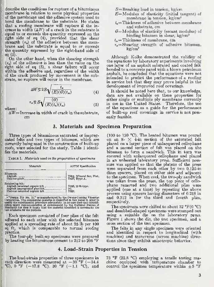
describe the conditions for rupture of a bituminousmembrane in relation to some physical properties
of the membrane and the adhesive system used to
bond the membrane to the substrate. He states
that a roofing membrane will rupture if the in-
crease in width (AW) of a crack in the substrate is
equal to or exceeds the quantity expressed on theright side of eq (4), provided that the shearstrength (tq) of the adhesive between the mem-brane and the substrate is equal to or exceedsthe quantity expressed by the right-hand side of
eq (5).
On the other hand, when the shearing strength(tq) of the adhesive is less than the value on theright side of eq (5), a shear failure will occurwithin the adhesive and, regardless of the widthof the crack produced by movement in the sub-strate, no ruptiu"e will occiu" in the membrane.
/-
ta
(4)
(G)
(EKtaKU (5)
where
:
AW= Increase in width of crack in the substrate,
cm
)S=Breaking load in tension, kg/cmModulus of elasticity (initial tangent) of
membrane in tension, kg/cm^
fa= Thickness of adhesive between membraneand substrate, cm
(?= Modulus of elasticity (secant modulus) of
binding bitumen in shear, kg/cm^
fm= Thickness of membrane, cmra= Shearing strength of adhesive bitumen,
kg/cm^
Although Koike demonstrated the validity of
the equations by laboratory experiments involvingone layer of an asphalt saturated and coated felt
bonded to a concrete panel with a blown petroleumasphalt, he concluded that the equations were notintended to predict the performance of a roofing
in service but that they may prove helpful in the
development of improved roof coverings.
It should be noted here that, to our knowledge,data are not available on these properties for
either single or multiple ply membrane currently
in use in the United States. Therefore, the useof the equations as a guide for the performanceof built-up roof coverings in service is not pres-
ently feasible.
3. Materials and Specimen Preparation
fe!Three types of bituminous saturated or impreg-
,1nated felts and two types of bitumen, which are
ji currently being used in the construction of buUt-up
jj!
roofs, were selected for the study. Table 1 identi-' fies the materials.
Table 1. Materials used in the preparation of specimens
Materials
Bitumens:AsphaltCoal-tar-pitch.
Beinforcing felt:
Asphalt saturated organic felt .
Asphalt impregnated glass felt.
Coal-tar saturated organic felt_.
ASTM Specification
D312, Mineral Sur. Flat.D450, Type A.
D226, 15 lb type.(»).
D227.
» "Perma Ply No. 11," as manufactured by the Owens-Corning Fiberglas'j| Corporation. The commercial material is identified in this paper in order to
specify the experimental procedure adequately. In no case does such identifi-
cation imply recommendation or endorsement by the National Bureau of
Standards nor does it imply that the material identified is necessarily thebest available for the purpose.
Each specimen consisted of four plies of the felt
adhered to each other with the selected bitumen
[j
applied at a spreading rate of about 25 lb per 100sq ft, which is comparable to normal roofing
J
practice.
yThe four-ply built-up specimens were prepared
Iby heating the bituminous cement to 212 to 266 °F
(100 to 130 °C). The heated bitumen was pouredon an 8- X 4-in section of the saturated felt
placed on a larger piece of imlacquered cellophaneand a second section of felt was placed on the
bitumen to form a sandwich. This in turn wascovered with imlacquered cellophane and placedin an unheated laboratory press. Sufficient pres-
sure was applied so that the platens of the press
were separated from each other by two 0.125-in
diam spacers, placed on either side and adjacentto the specimen. When cool, the two-ply sandwichwas taken from the press, the top piece of cello-
phane removed and two additional plies wereapplied (one at a time) by repeating the aboveprocess using spacers having diameters of 0.218 in
and 0.312 in for the third and fourth plies,
respectively.
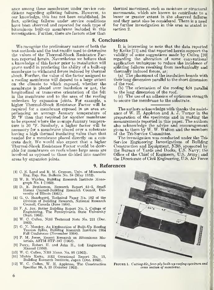
The specimens were chilled to about 32 °F(0 °C)and dumbbell-shaped specimens were stamped outusing a suitable die on the laboratory press.
Figure 1 shows the die, the test specimen, and across section of the test specimen.
The felts in any single specimen were orientedand identified in respect to longitudinal (withmachine) and transverse (across machine) direc-
tions since they exhibit anisotropic behavior.
4. Load- Strain Properties in Tension
The load-strain properties of three specimens in
each direction were measured at —30 °F (— 34.4°C), 0 °F (-17.8 °C). 30 °F (-1.1 °C), and
73 °F (22.8 °C) employing a tensile testing ma-chine equipped with temperature chamber to
control the specimen temperature mthin ±5 °F
J
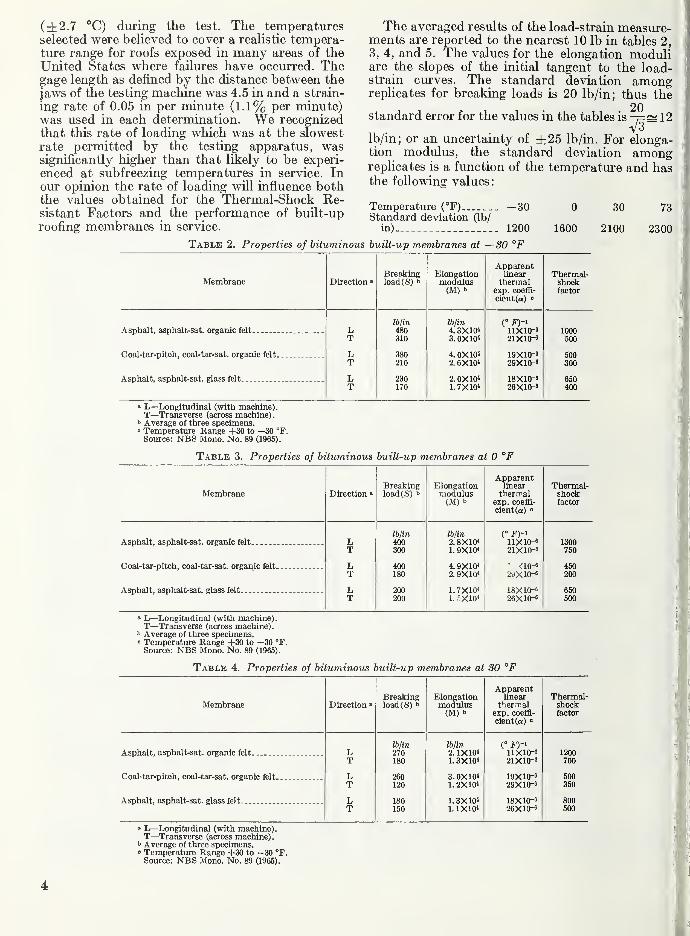
(±2.7 °C) during the test. The temperaturesselected were believed to cover a realistic tempera-ture range for roofs exposed in many areas of theUnited States where failures have occurred. Thegage length as defined by the distance between the
jaws of the testing machine was 4.5 in and a strain-
ing rate of 0.05 in per minute (1.1% per minute)was used in each determination. We recognizedthat this rate of loading which was at the slowestrate permitted by the testing apparatus, wassignificantly higher than that likely to be experi-
enced at subfreezing temperatures in service. Inour opinion the rate of loading will influence boththe values obtained for the Thermal-Shock Re-sistant Factors and the performance of built-up
roofing membranes in service.
Table 2. Properties of bituminous built-up membranes at —SO °F
The averaged results of the load-strain measure-ments are reported to the nearest 10 lb in tables 2,
3, 4, and 5. The values for the elongation moduliare the slopes of the initial tangent to the load-strain curves. The standard deviation amongreplicates for breaking loads is 20 lb/in; thus the
20standard error for the values in the tables is -7=^ 12
V3lb/in; or an uncertainty of ±25 lb/in. For elonga-tion modulus, the standard deviation amongreplicates is a function of the temperature and hasthe following values:
Temperature (°F) —30 0 30 73Standard deviation (lb/
in) 1200 1600 2100 2300
ApparentBreaking Elongation linear Thermal-
Membrane Direction • loadCS) b modulus thermal shock(M) b exp. coeffi- factor
cient (a) "
lb/in lb/in (° F)-^Asphalt, asphalt-sat. organic felt L 480 4.3X10< nxio-6 1000
T 310 3. OXW 21X10-' 500
Coal-tar-pitch, coal-tar-sat. organic felt L 380 4. 0X10* 19X10-8 500T 210 2. 6X10< 29X10-' 300
Asphalt, asphalt-sat. glass felt L 230 2. 0X104 18X10-' 650T 170 1. 7X10⁴ 26X10-' 400
' L—Longitudinal (with machine).T—Transverse (across machine).
' Average of three specimens.• Temperature Range +30 to —30 °F.Source: NBS Mono. No. 89 (1965).
Table 3. Properties of bituminous built-up membranes at 0 °F
Membrane Direction »Breakingload(S) b
Elongationmodulus(M) b
Apparentlinearthermal
exp. coeffi-
cient (a) 0
Thermal-shockfactor
Ibjin lb/in
Asphalt, asphalt-sat. organic felt L 400 2.8X10⁴ 11X10-' 1300T 300 1. 9X10⁴ 21X10-' 750
Coal-tar-pitch, coal-tar-sat. organic felt L 400 4.9X10⁴ ' <io-« 450T 180 2. 9X10⁴ 2aX10-' 200
Asphalt, asphalt-sat. glass felt L 200 1.7X10⁴ 18X10-' 650T 200 1. r-X10» 26X10-' 500
" L—Longitudinal (with machine).T—Transverse (across machine),
b Average of three specimens.0 Temperature Range +30 to —30 °r.Source: NBS Mono. No. 89 (1965).
Table 4. Properties of bituminous built-up membranes at SO °F
ApparentBreaking Elongation linear Thermal-
Membrane Direction » load(S) b modulus thenral shock(M) b exp. coeffi- factor
cient (a) 0
lb/in lb/in C f)-Asphalt, asphalt-sat. organic felt L 270 2.1X10⁴ 11X10-9 1200
T 180 1.3X10⁴ 21X10-' 700
Coal-tar-pitch, coal-tar-sat. organic felt L 260 3. 0X104 19X10-' 500T 120 1. 2X10⁴ 29X10-' 350
Asphalt, asphalt-sat. glass felt L 180 1.3X10⁴ 18X10-' 800T 150 1.1X10⁴ 26X10-' 500
» L—Longitudinal (with machine).T—Transverse (across machine),
b Average of three specimens.<= Temperature Range +30 to —30 °F.Source: NBS Mono. No. 89 (1965).
4
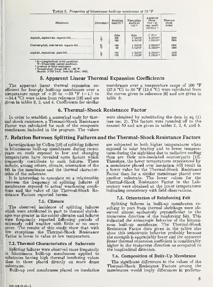
Table 5. Properties of bituminous built-up membranes at 73 °F
ATpttiHron ft DirectionBreaking Elongation
moQuliis(M) t>
Apparentlinear
t Vi Of )' ct I
6Xp. C06fl^~
cient(a) °
Thermal-
fsctor
Iblin Iblin (° F)'iAsphalt, asphalt-sat. organic felt L 190 1. 9X10< 3.2X10-' 3000
T 130 9 4X10^ 5 3X10"' 2600
Coal-tar-pitch, coal-tar-sat. organic felt L 160 1.3X10'' 2. 0X10-' 6150T 90 5. 2X10³ 3.2X10⁻³ 5400
Asphalt, asphalt-sat. glass felt. , L 180 1.4X10* 2.6X10-3 5150T 170 1.2X10« 2. 5X10⁻³ 5650
» L—Longitudinal (with machine)
.
T—Transverse (across machine).•> Average of three specimens." Temperature Range 100 to -60 °F.Source: NBS Tech. Note 231 (De;. 1963).
5. Apparent Linear Thermal Expansion Coefficients
The apparent linear thermal expansion co-
efficient for four-ply built-up membranes over atemperature range of -f-SO to —30 °F (—1.1 to
— 34.4 °C) were taken from reference [10] and are
given in tables 2, 3, and 4. Coefficients for similar
membranes over a temperature range of 100 °F(37.8 °C) to 60 °F (15.6 °C) were calculated fromthe curves given in reference [6] and are given in
table 5.
6. Thermal- Shock Resistance Factor
In order to establish a numerical scale for ther-
mal shock resistance, a Thermal-Shock ResistanceFactor was calculated for each of the compositemembranes included in the program. The values
7. Relation Between Splitting Failures and the Thermal-Shock Resistance Factors
were obtained by substituting the data in eq (1)
(see sec. 2). The factors were rounded off to the
nearest 50 and are given in tables 2, 3, 4, and 5.
Investigations by Cullen [10] of splitting failures
in bituminous built-up membranes during recent
years on roofs exposed to low and changingtemperatures have revealed some factors whichfrequently contribute to such failures. Theseinclude, among others, climate, orientation of the
felt in the membrane and the thermal character-
istics of the substrate.
It is interesting to speculate on a relationship
between the frequency of splitting failures of
membranes exposed to actual weathering condi-
tions and the value of the Thermal-Shock Re-sistance Factors reported herein.
7.1. Climate
The observed incidence of splitting failures
which were attributed in part to thermal shrink-ages was greater in the colder climates and failures
were frequently reported following periods of
extremely cold weather with little or no snowcover. The results of this study show that withfew exceptions the Thermal-Shock ResistanceFactor is lower in value at low temperature.
7.2. Thermal Characteristics of Substrate
Splitting failiu"es were observed more frequentlyin bituminous built-up membranes applied to
substrates having high thermal insulating valuesthan in those placed directly on more densesubstrates.
Built-up roof membranes placed on insulation
are subjected to both higher temperatures whenexposed to solar heating and to lower tempera-tures during the nighttime due to radiative cooling
than are their non-insulated counterparts [12].
Therefore, the lower temperatures experienced bya membrane placed over insulation will result in
a lower value for the Thermal-Shock ResistanceFactor than for a similar membrane placed over
another substrate. The lower values for the
Thermal-Shock Resistance Factor in the Lab-oratory were obtained at the lower temperaturesindicating consistency with field observations.
7.3. Orientation of Reinforcing Felt
Splitting failures in built-up membranes re-
sulting in part from thermal shrinkage were ob-
served almost exclusively perpendicular to the
transverse direction of the reinforcing felt. Thisindicated the anisotropic behavior of the bitumi-nous built-up membrane. The Thermal-ShockResistance Factor data given in the tables also
show this anisotropic behavior probably becausethe strength is appreciably lower and the apparentlinear thermal expansion coefficient is considerably
higher in the transverse direction as compared to
the longitudinal direction.
7.4. Composition of Built-Up MembraneThe significant differences in the values of the
Thermal-Shock Resistance Factors among the
membranes would imply differences in perform-
^ 259-508 0-67-2
ance among these membranes under service con-
ditions regarding splitting failures. However, to
our knowledge, this has not been established. Infact, splitting failures under service conditions
have been observed and reported for each type of
bituminous built-up membrane included in this
investigation. Further, there are factors other than
thermal movement, such as moisture or structuralmovements, which are known to contribute to alesser or greater extent in the observed failures
and they must also be considered. There is a needfor further investigation in this area as stated in
section 2.
8. Conclusions
We recognize the preliminary nature of both the
test methods and the test resiilts used to determinethe values of the Thermal-Shock Resistance Fac-tors reported herein. Nevertheless we believe that
a knowledge of this factor prior to installation wUlprove useful in predicting the ability of a built-up
membrane to withstand forces induced by thermalshock. Further, the value of the factor assigned to
a roofing memljrane will depend to a large extent
on the climate to which exposed, whether the
membrane is placed over insulation or not, the
longitudinal or transverse orientation of the felt
in the membrane and to the area of the roofing
unbroken by expansion joints. For example, ahigher Thermal-Shock Resistance Factor will berequired for a membrane exposed in an area ex-
periencing an average January temperature of
20 °F than that required for another membraneto be exposed where the average January tempera-ture is 30 °F. Similarly, a higher factor will benecessary for a membrane placed over a substrate
having a high thermal insulating value than that
needed for a membrane placed directly on a con-
crete deck. We would also expect that a higher
Thermal-Shock Resistance Factor would be desir-
able for membranes on roofs where large areas are
involved as opposed to those divided into smaller
areas by expansion joints.
It is interesting to note that the data reportedby Koike [11] and that reported herein support thevalidity of some suggestions made by Cullen [10]
regarding the alteration of some conventionalapplication techniques to reduce the incidence of
splitting failures resulting from mechanically andthermally induced forces, as:
(a) The placement of the insulation boards withtheir long dimension parallel to the short dimensionof the roof.
(b) The orientation of the roofing felt parallel
to the long dimension of the roof.
(c) The use of an adhesive of optimum strengthto secure the membrane to the substrate.
The authors acknowledge with thanks the assist-
ance of W. H. Appleton and A. J. Turner in thepreparation of the specimens and in making themeasurements reported in this paper. The authorsalso acknowledge the advice and encouragementgiven to them by W. W. Walton and the membersof the Tri-Service Committee.The investigation was conducted under the Tri-
Service Engineering Investigations of BuildingConstruction and Equipment, NBS, sponsored bythe Bureau of Yards and Docks, U.S. Navy; the
Office of the Chief of Engineers, U.S. Army; andthe Directorate of Civil Engineering, U.S. Air Force
9. References
[1] C. E. Lund and R. M. Granum, Univ. of MinnesotaEng. Exp. Stn. Bulletin No. 34 (May 1952).
[2] W. B. Warden, Building Research Institute Mono-graph No. 1 (I960).
[3] D. E. Brotherson, Research Report 61-2, SmallHomes Council-Building Research Council, Uni-versity of Illinois (1961).
[4] G. O. Handegord, Technical Paper No. 182 of theDivision of Building Research, National ResearchCouncil, Canada (June 1964).
[5] F. A. Joy, Better Building Report No. 5, College of
Engineering, The Pennsylvania State University(Sept. 1963).
[6] W. C. Cullen, NBS Technical Note No. 231 (Dec.1963).
[7] G. N. Moseley, An Explanation of Built-Up RoofingTension Splits, Building Research Institute 1964Fall Conference (November 1964).
[8] P. M. Jones, Recent Research on Bituminous Ma-terials, ASTM STP-347 (1963).
[9] Perry, Robert H. and John H., (ed) EngineeringManual (1959).
[10] W. C. Cullen, NBS Mono. No. 89 (1965).
[11] Michio Koike, BRI Occasional Report No. 15,Building Research Institute, Japan (Dec. 1963).
[12] W. C. Cullen, W. H. Appleton, The ConstructionSpecifier 16, 5, 35 (October 1963).
Figure 1 . Cutting die, four-ply built-up roofing specimen andcross section of membrane.
6
Section 2
Thermal-Shock Resistance for Bituminous Built-up RoofingMembranes—Its Relation to Service Life
William C. GuUen and Thomas H. Boone
The assignment of a service life to a bituminous built-up roofing system is frequentlydifficult because of the many variables involved. A knowledge of these variables, and of
their effect on the performance of the total building system, will greatly assist in the selec-
tion of a roofing assembly and the assignment of a service life to such an assembly.Some of the factors such as breaking load in tension, modulus of elongation, and appar-
ent linear thermal expansion coefficient of roofing membranes of different composition aregiven for both laboratory-prepared and field-obtained samples. Membranes of 2, 3, and4-plies of felt are included. The relations of some engineering properties of a roofing membraneto performance in service as expressed by a Thermal-Shock Resistance Factor are also given.
Ways and means to reduce potential failures of bituminous built-up roofing membranesresiilting from thermally induced forces are discussed.
Key Words: Bituminous-built-up roofing, roofing membrane, service life, thermal-shock resistance factor, tension splitting.
Contents
Page' 1. Introduction 7
ij 2. Experimental detail 82.1. Materials and specimen preparation 8
i( a. Laboratory 8ji b. Field 8
2.2. Load-strain properties in tension 9I 2.3. Linear thermal expansion 9
j3. Results 9
i 4. Discussion of results 94.1. Effect of number of plies of reinforcing felt on
the strength characteristics of a built-upmembrane 9
!4.2. Relation between values of thermal-shock
Iresistance factors and performance in field
i service 11' 5. Comments 12i 6. References 13
1. Introduction
Any ruptiire of the waterproofing element of a
I roofing assembly generally leads to failure of the
Itotal assembly, from both a weatherproofing and
jj
a heat transfer viewpoint. Moseley [1] ' has indi-
Icated that tension splits which occur in the built-
I
up membrane are frequent causes of failure. Cullen[2] suggested that the thermal movement which
ioccurs in a bituminous built-up roofing membrane
,
due to rapid temperature changes is often a con-
j
tributing factor in tension splits. He proposed the
Iutilization of a Thermal-Shock Resistance Factor
1to predict the ability of a built-up membrane to
Itolerate, without rupture, the forces, induced by
IIsuch temperature changes [3].
i 1 Figures in brackets indicate the literature references at the end of thist paper.
A roofing membrane will rupture when the
thermal contraction equals or exceeds the ultimate
elongation of the membrane. Since the force-exten-
sion curve is approximately linear below 30 °F
(—1.1 °C), the ratio of tensile strength (S) to
modulus of elongation (M) may be used to estimate
the ultimate elongation. Thermal contraction is
proportional to the coefficient of linear thermal
expansion (a). Hence the merit of a membranemay be expressed by a Thermal-Shock Resistance
Factor (TSRF) given by the following eq (1)
^^^^'^Wc (1)
7
where
T<S'i?Fi= Thermal-Shock Resistance Factor<S'=Breaking load, lb/in (see footnote 2)
M= Modulus of elongation (initial tan-
gent), lb/in (footnote 2)
Q:=Linear thermal expansion, per °F.
From this equation, it is seen that the higherthe breaking load, the lower the coefficient of linear
thermal expansion, and the lower the modulus of
elongation, the more resistant to rupture is themembrane under thermal changes.
Cullen and Boone reported values for TSRF of
three convential membranes at temperatures of
-30 °F (-34.4 °C), 0 °F (-17.8 °C), 30 °F(-1.1 °C), and 73 °F (22.8 °C) in section 1 of
this publication.
This paper presents values for Thermal-ShockResistance Factors at 0 °F (—17.8 °C) for four
built-up membranes constructed in the laboratory,
consisting of 2, 3, and 4 plies of felt, respectively.
In addition values for samples of bituminousbuilt-up roofs with up to 25 years exposure in
service are also given. In some cases the roof
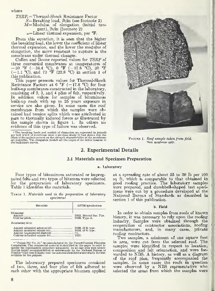
membranes from which the samples were ob-tained had tension splits which were attributed in
part to thermally induced forces as Ulustrated bythe sample shown in figiu'e 1. In others noevidence of this type of faUiu'e was observed.
2 The breaking loads and moduli of elongation are expressed in poimdsper inch width of membrane since a previous study [4] had shown that theeffect of the asphalt-cement on the strength characterisitcs of the membraneare negligible. The elongation moduli are the slopes of the initial tangent tothe load-strain curves.
>
FiGURK 1. Roof sample taken from field.
Note membrane split.
2. Experimental Details
2.1 Materials and Specimen Preparation
a. Laboratory
Four types of bituminous saturated or impreg-nated felts and two types of bitumen were selected
for the preparation of laboratory specimens.Table 1 identifies the materials.
Table 1. Materials used in the preparation of laboratory
specimens
Materials ASTM specification
Bitumens:Asphalt _.. . D312, Mineral Sur. Flat.
D450, Type A.
D250, 15 lb type.D226, 15 lb type.
w.D227.
Coal-tar-pitch ___
Reinforcing felts:
Asphalt saturated asbestos felt.-.
Asphalt saturated organic felt
Asphalt impregnated glass felt...
Coal-tar saturated organic felt ...
a "Penna Ply No. 11," as manufactured by the Owens-Commg FiberglasCorporation. The commercial material is identified in this paper in order tospecify the experimental procedure adequately. In no case does such identi-fication imply recommendation or endorsement by the National Bureau ofStandards nor does it imply that the material identified is necessarily the bestavailable for the purpose.
The laboratory prepared specimens consistedof two, three, and four plies of felt adhered to
each other with the appropriate bitumen applied
at a spreading rate of about 25 to 30 lb per 100sq ft, which is comparable to that obtained in
good roofing practice. The laboratory samples.
were prepared, and dumbbell-shaped test speci-
mens were cut by a procedure developed at the
National Bureau of Standards as described in
section 1 of this publication.
b. Field
In order to obtain samples from roofs of knownhistory, it was necessary to rely upon the roofing '
industry. Samples were obtained through the i
cooperation of contractor associations, roofing 'I
manufacturers, and, in many cases, private ?
roofing contractors. i
Two samples, a minimum of one square foot I
in area, were cut from the selected roof. The t
samples were identified in respect to location,'
composition and felt orientation, and were for- (
warded to NBS. A history, as weU as a diagram '
of the roof plan, frequently accompanied the )
samples. In some cases the roofs in question i
were observed by a NBS representative who\
selected the areas from which the samples were
8
to be removed. In the cases where tension splits
were apparent, samples were taken at or nearthe failure.
Information on the field samples relative to
the location, age, composition, and number of
plies is given in table 3.
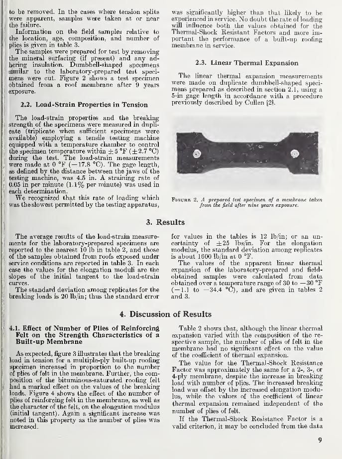
The samples were prepared for test by removingthe mineral surfacing (if present) and any ad-hering insulation. Dumbbell-shaped specimenssimilar to the laboratory-prepared test speci-
mens were cut. Figure 2 shows a test specimenobtained from a roof membrane after 9 yearsexposm-e.
2.2. Load-Strain Properties in Tension
was significantly higher than that likely to beexperienced in service. No doubt the rate of loadingwill influence both the values obtained for theThermal-Shock Resistant Factors and more im-portant the performance of a built-up roofingmembrane in service.
2.3. Linear Thermal Expansion
The linear thermal expansion measurementswere made on duplicate dumbbell-shaped speci-mens prepared as described in section 2.1, using a5-in gage length in accordance with a procedurepreviously described by CuUen [21.
The load-strain properties and the breakingstrength of the specimens were measured in dupli-
! cate (triplicate when sufficient specimens wereavailable) employing a tensUe testing machineequipped with a temperature chamber to control
the specimen temperature within ±5 °F (±2.7 °C)during the test. The load-strain measurements
I
were made at 0 °F (-17.8 °C). The gage length,
as defined by the distance between the jaws of thetesting machine, was 4.5 in. A straining rate of
0.05 in per minute (1.1% per minute) was used in
each determination.We recognized that this rate of loading which
Iwas the slowest permitted by the testing apparatus.
Figure 2. A prepared test specimen of a membrane takenfrom the field after nine years exposure.
3. Results
The average results of the load-strain measure-ments for the laboratory-prepared specimens are
reported to the nearest 10 lb in table 2, and those
of the samples obtained from roofs exposed underservice conditions are reported in table 3. In eachcase the values for the elongation moduli are the
slopes of the initial tangent to the load-strain
curves.
The standard deviation among replicates for the
breaking loads is 20 lb/in; thus the standard error
for values in the tables is 12 lb/in; or an un-certainty of ±25 lbs/in. For the elongationmodulus, the standard deviation among replicates
is about 1600 lb/in at 0 °F.
The values of the apparent linear thermalexpansion of the laboratory-prepared and field-
obtained samples were calculated from dataobtained over a temperature range of 30 to —30 °F(—1.1 to —34.4 °C), and are given in tables 2
and 3.
4. Discussion of Results
4.L Effect of Number of Plies of ReinforcingFelt on the Strength Characteristics of aBuilt-up Membrane
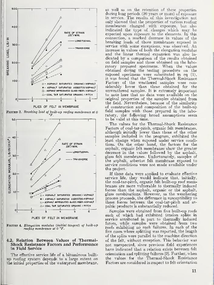
As expected, figure 3 illustrates that the breakingload in tension for a multiple-ply built-up roofing
specimen increased in proportion to the numberof plies of felt in the membrane. Further, the com-position of the bituminous-satiu-ated roofing felt
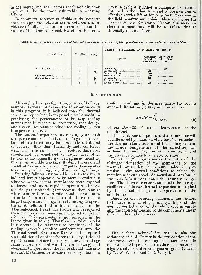
had a marked effect on the values of the breakingloads. Figure 4 shows the effect of the number of
plies of reinforcing felt in the membrane, as well as
the character of the felt, on the elongation modulus(initial tangent). Again a significant increase wasnoted in this property as the number of plies wasincreased.
Table 2 shows that, although the linear thermalexpansion varied with the composition of the re-
spective sample, the number of plies of felt in the
membrane had no significant effect on the valueof the coefficient of thermal expansion.
The value for the Thermal-Shock ResistanceFactor was approximately the same for a 2-, 3-, or
4-ply membrane, despite the increase in breakingload with number of plies. The increased breakingload was offset by the increased elongation modu-lus, while the values of the coefficient of linear
thermal expansion remained independent of the
number of plies of felt.
If the Thermal-Shock Resistance Factor is a
valid criterion, it may be concluded from the data
9
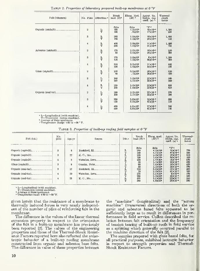
Table 2. Properties of laboratory prepared built-up membranes at 0 °F
Felt (bitumen) No. Plies Direction "Break
load (S)bElong. Mod.
(M) bAppar. lin.
therm, expcoeff. (a) "
Thermal-Shockfactor
lb/in Ibjin
Organic (asphalt) 2 L 180 1. SXIO* 10X10-' 1, 350T 130 .9X10< 17X10-6 '850
3 L 280 1.9X10^ 10X10"' 1 600T 180 1.2X10^ 24X10-6 '650
4 L 400 2.8X10" 11X10-6 1, 300T 300 1.9X10< 21X10-6 '750
Asbestos (asphalt) 2 L 170 2.0X10* 10X10-6 850T 80 0. 9X10« 26X10-6 300
3 L 270 2.8X10' 8X10⁻⁶ 1, 200T 120 1.3X10* 30X10-6 '300
4 L 310 3.3X10'' 11X10-6 850T 130 1. 6X10« 32X10-6 260
Glass (asphalt) 2 L 110 0. 9X10* 20X10-6 620T 80 . 7X101 20X10-6 600
3 L 160 1. 3X10* 22X10-6 540T 140 1.1X10* 35X10-6 360
4 L 210 1. 6X10* 20X10-6 660T 180 1.3X10* 22X10-6 610
Organic (coal tar) 2 L 200 2. 5X10* 22X10-6 370T 100 1. 7X10* 33X10-6 190
3 L 330 3.9X10* 25X10-6 3301 150 42X10"^ 110
4 L 450 4.8X10* 27X10-6 350T 220 3.9X10* 42X10-6 140
" L—Longitudinal (with machine).T—Transverse (across machine)
.
Average of thiree specimens.« Temperature Range 4-30 to —30 ° F.
Table 3. Properties of built-up roofing field samples at 0 °F
Dir.'Break
load (S) bElong. mod.
(M) bAppar. lin.
therm, exp.coefE. (a) 0
Thermal-shockfactor
Iblin Ibjin
L 240 4. 5X10* 16X10-6 750T 140 4. 7X10* 41X10-6 500L 220 2.3X10* 15X10-6 620T 130 1.6X10* 30X10-6 260L 230 1.4X10* 25X10-6 650T 80 1.1X10* 23X10-6 350L 90 1.8X10* 20X10-6 450T 80 1. 2X10* 19X10-6 350L 210 3.8X10* 20X10-6 300T 70 2. 0X10* 31X10-6 100
L 270 5. 1X10* 9X10-8 550T 200 2.5X10* 16X10-6 500L 490 5. 1X10* 13X10-6 560T 260 4. 9X10* 23X10-6 230
Felt (bit.)
No.plies Age yr Source
Organic (asphalt)
Organic (asphalt)
Organic (asphalt)
Glass (asphalt)..
Organic (coal-tar)
Organic (coal-tar)
Organic (coal-tar)
22
12
20
25
Rockford, ni...
K. C, Mo
Waterloo, Iowa.
Omaha, Nebr.
.
Rockford, HI...
Waterloo, Iowa
K. C, Mo
» L—Longitudinal (with machine).T—Transverse (across machine)
.
b Average of three specimens.« Temperature range 4-30 to —30 °F.
given herein that the resistance of a membrane to
thermally induced forces is very nearly independ-ent of the number of plies of reinforcing felt in themembrane.The difference in the values of the linear thermal
expansion property in respect to the orientation
of the felt in a buUt-up membrane has previouslybeen reported [2]. The values of the engineeringproperties and those of the Thermal-Shock Resist-
ance Factors reported here also reflected the aniso-
tropic behavior of a built-up roofing membraneconstructed from organic and asbestos base felts.
The difference in value of these properties between
the "machine" (longitudinal) and the "across
machine" (transverse) directions of both the or-
ganic and asbestos based felts appeared to besufficiently large as to result in differences in per-
formance in field service. CuUen described the re-
lation between felt orientation and the frequencyof tension tearing of built-up roofs in field service
as a splitting which generally occurred parallel to
the machine direction of the felt [2].
The samples prepared with glass based felts, for
all practical purposes, exhibited isotropic behaviorin respect to strength properties and Thermal-Shock Resistance Factors.
10
-ASPHALT IMPREGNATED GLASS FIBER / ASPHALT
A- COAL TAR SATURATED ORGANIC / PITCH
PLIES OF FELT IN MEMBRANE
Figure 3. Breaking load of built-up roofing membranes at 0°F.
• - ASPHALT SATURATED ASBESTOS /ASPHALT
O - ASPHALT IMPREGNATED GLASS FIBER /ASPHALT
A- COAL TAR SATURATED ORGANIC / PITCH
PLIES OF FELT IN MEMBRANE
Figure 4. Elongation modulus {initial tangent) oj built-up
roofing membranes at 0 °F.
4.2. Relation Between Values of Thermal-Shock Resistance Factors and Performancein Field Service
The effective service life of a bituminous built-
up roofing system depends to a large extent onthe initial properties of the waterproof membrane,
as well as on the retention of these propertiesdiiring long periods (20 years or more) of exposurein service. The results of this investigation notonly showed that the properties of various roofingmembranes changed with exposure, but also
indicated the type of changes which may beexpected upon exposure to the elements. In this
connection, a marked decrease in values of thebreaking loads of those membranes exposed in
service with some exceptions, was observed. Anincrease in values of both the elongation modulusand the linear thermal expansion was also in-
dicated by a comparison of the results obtainedon field samples and those obtained on the labo-ratory prepared specimens. When the valuesobtained during the testing procedure on theexposed specimens were substituted in eq (1),
it was found that the Thermal-Shock ResistanceFactors of the weathered samples were con-siderably lower than those obtained for theunweathered samples. It is extremely importantto note here that no data were available on theoriginal properties of the samples obtained fromthe field. Nevertheless, because of the similarity
of construction and composition of the built-upfield samples vnth those prepared in the labo-ratory, the foUomng broad assumptions seemto be valid at this time.
The values for the Thermal-Shock ResistanceFactors of coal-tar-pitch, organic felt membranes,although initially lower than those of the othersamples included in the program, exhibited theleast change when exposed under service condi-tions. On the other hand, the factors for theasphalt, organic felt membranes show the greater
decrease in the values followed by the asphalt,
glass felt membranes. Unfortunately, samples of
the asphalt, asbestos felt membrane exposed to
service conditions were not made available underthe project.
If these data were applied to evaluate effective
service life, they would indicate that, initially,
the coal-tar-pitch, organic felt buUt-up roof mem-branes are more vulnerable to thermally inducedforces than the asphalt, organic or the asphalt,
glass combinations. However, as the weatheringprocess proceeds, the difference in susceptibility to
these forces between the coal-tar-pitch and as-
paltic products is substantially reduced.
Samples were obtained from five built-up roofs
each of which had exhibited tension splits in
service attributed in part to thermally inducedforces, while samples were obtained from tworoofs exhibiting no such failures. In each of the
five cases where splitting was reported, the length
of the splits were parallel to the machine direction
of the felt, without exception. This behavior was
not unexpected, since previous field experiences
have indicated that a relation exists between felt
orientation and splitting faUiu-es [2]. Further, whenthe values for the Thermal-Shock Resistance
Factors are considered in respect to felt orientation
11
in the membrane, the "across machine" direction
appears to be the most vulnerable to splitting
failure.
In summary, the results of this study indicates
that an apparent relation exists between the in-
cidence of splitting failure in a membrane and thevalues of the Thermal-Shock Resistance Factor as
given in table 4. Further, a comparison of resultsobtained in the laboratory and of observations ofeffective service life of buUt-up roofing systems inthe field, confirm our opinion that the higher theThermal-Shock Resistance Factor, the more re-
sistant a membrane will be to failure due tothermally induced forces.
Table 4. Relation between values of thermal shock-resistance and splitting failures observed under service conditions
Felt (bitumen) No. plies Age yr.
Thermal shock-resistance factor (transverse direction)
SourceMembraneexhibiting
tension splits
No evidenceof tension
splits
Organic (asphalt)
.
Glass (asphalt)Organic (coal-tar) _
6
22
12
2025
Rockford, niKansas City, Mo.Waterloo, Iowa. .
.
Omaha, NebrRockford, ElWaterloo, Iowa.__Kansas City, Mo.
260350350100
500
230500
5. Comments
Although all the pertinent properties of built-up
membranes were not demonstrated experimentallyin this program, it is believed that the thermalshock concept which is proposed may be useful in
predicting the performance of buUt-up roofing
membranes in respect to properties, roof design,
and the environment in which the roofing systemis expected to serve.
The authors' experience over many years withthe performance of built-up roofings in service
had indicated that many failures can be attributed
to factors other than thermally induced forces
with which this paper deals. Therefore, this papershould not be construed to imply that otherfactors as mechanically induced stresses, moisturemigration, wrinkle cracking, flashing failures, andchemical degradation are not important considera-tions in many bituminous built-up roofing failures.
Splitting failures attributed in part to thermallyinduced forces appeared to be more prevalent in
climates where roofing membranes were exposedto larger and more rapid temperature changesespecially at subfreezing temperature than in areaswhere temperatures were mUder and more uniform.In order for a membrane to resist forces due to
large temperature changes at subfreezing tempera-tures, it follows that a higher value for theThermal-Shock Resistance Factor will be requiredthan for the same membrane exposed to milderclimates. This parameter is not reflected in thefactor given in eq (1). Therefore, in order to takeinto account the temperature conditions of theroofing system's ambient environment into theThermal-Shock Resistance Factor, it is proposedthat addition of another factor to the right side of
eq (1) be made. Since thermally induced shrinkagefailures are associated with low (subfreezing) andchanging temperatures, the factor should take intoaccount the temperatures experienced by a built-up
roofing membrane in the area where the roof is
exposed. Equation (1) may now be written:
TSRFo_S ]_~Ma Atm (2)
where: A^m=32 °F minus (temperature of themembrane).The membrane temperature at any one time will
be influenced by a number of factors. These includethe thermal characteristics of the roofing system,the inside temperature of the structure, theambient temperature, the wind conditions, andthe presence of moisture, water or snow.Equation (2) approximates the ratio of the
ultimate elongation of the membrane to thethermal contraction that occurs under the par-ticular environmental conditions to which themembrane is subjected. As mentioned previously,
the ratio S/M approximates the ultimate elonga-tion. The thermal contraction equals the averagecoefficient of linear thermal expansion multipliedby the actual change in temperature of themembrane.Based on the foregoing comments the authors
feel there is a need for investigations of theengineering behavior of the whole roof assemblyand the interrelationship of its components underdifferent thermal exposures.
The authors acknowledge with thanks the
assistance of A. J. Turner in the preparation of the
specimens and in making the measurementsreported in this paper. The authors also acknowl-edge the advice and encouragement given to themby W. W. Walton and J. R. Wright.
12
The authors appreciate the assistance of EdwinCarlson, Jim Lenzner, Tom Manson, Paul Morris,
and Milton Olsen of the Midwest Roofing Con-
tractors Association, Inc., in making available
exposed roof cutouts and first-hand knowledge of
their performance.
6. References
[1] G. N. Moseley, built-up roofing tension splits, TheJournal of the Building Research Institute 1, No.6, 31 (Nov.-Dec. 1964).
[2] W. C. CuUen, Effects of thermal shrinkage on built-uproofing, NBS Mono. No. 89 (1965).
[3] W. C. Cullen, Solar heating, radiative cooling andthermal movement—Their effects on built-up roof-
ing, NBS tech. Note 231 (Dec. 1963).
[4] P. M. Jones, Recent research on bituminous materials,ASTM STP-347 Am. Soc. Testing Mats. (1963).
13U.S. GOVERNMENT PRINTING OFFICE : 1967—O-259-508
ANNOUNCEMENT OF NEW PUBLICATIONS INBUILDING SCIENCE SERIES
Superintendent of Documents,
Government Printing Office,
Washington, D.C. 20402
Dear Sir
:
Please add my name to the announcement list of new publications to be
issued in the series: National Bureau of Standards Building Science Series.
Name
Company
Address
City State Zip Code
(Notification key N-339)
RELATED PUBLICATIONS
NBS Monograph 28—Causes of Variation in Chemical Analyses
and Physical Tests of Portland Cement—25 cents*
NBS Monograph 43—Chemistry of Cement Proceedings of the
Fourth International Symposium—Washington 1960. Presented
in two volumes. Volume I—$6.50. Volume II—$6.25. The two
volumes at $12.75 a set. (Originally issued September 1962, and
reprinted February 1964.)
NBS Building Science Series 2—Interrelations between Cement and
Concrete Properties. Part 1—35 cents. Section 1, Materials and
Techniques. Section 2, Water Requirements of Portland Cement.
Section 3, Occurrence of Minor and Trace Elements in Portland
Cement.
*Order publications from Superintendent of Documents, Government Printing
Office, Washington, D.C. 20402. (For foreign mailing, add one-fourth of the
price of the publication.)
THE NATIONAL BUREAU OF STANDARDS
The National Bureau of Standards^ provides measurement and technical information services
essential to the efficiency and effectiveness of the work of the Nation's scientists and engineers. TheBureau serves also as a focal point in the Federal Government for assuring maximum application of
the physical and engineering sciences to the advancement of technology in industry and commerce. Toaccomplish this mission, the Bureau is organized into three institutes covering broad program areas of
research and services:
THE INSTITUTE FOR BASIC STANDARDS . . . provides the central basis within the United
States for a complete and consistent system of physical measurements, coordinates that system with the
measurement systems of other nations, and furnishes essential services leading to accurate and uniformphysical measurements throughout the Nation's scientific community, industry, and commerce. This
Institute comprises a series of divisions, each serving a classical subject matter area:
—Applied Mathematics—Electricity—Metrology—Mechanics—Heat—Atomic Physics—Physical
Chemistry—Radiation Physics—Laboratory Astrophysics-—Radio Standards Laboratory,- which
includes Radio Standards Physics and Radio Standards Engineering—Office of Standard Refer-
ence Data.
THE INSTITUTE FOR MATERIALS RESEARCH . . . conducts materials research and provides
associated materials services including mainly reference materials and data on the properties of ma-terials. Beyond its direct interest to the Nation's scientists and engineers, this Institute yields services
which are essential to the advancement of technology in industry and commerce. This Institute is or-
ganized primarily by technical fields:
—Analytical Chemistry—Metallurgy—Reactor Radiations—Polymers—Inorganic Materials—Cry-
ogenics-—Office of Standard Reference Materials.
THE INSTITUTE FOR APPLIED TECHNOLOGY . . . provides technical services to promote the
use of available technology and to facilitate technological innovation in industry and government. Theprincipal elements of this Institute are:
—Building Research—Electronic Instrumentation—Technical Analysis—Center for Computer Sci-
ences and Technology—Textile and Apparel Technology Center—Office of Weights and Measures
—Office of Engineering Standards Services—-Office of Invention and Innovation—Office of Vehicle
Systems Research—Clearinghouse for Federal Scientific and Technical Information^—Materials
Evaluation Laboratory—NBS/GSA Testing Laboratory.
1 Headquarters and Laboratories at Gaithersburg, Maryland, unless otherwise noted; mailing address Washington, D. C,20234.
2 Located at Boulder, Colorado, 80302.
3 Located at 5285 Port Royal Road, Springfield, Virginia 22151.
U.S. DEPARTMENT OF COMMERCEWASHINGTON, D.C. 20230
POSTAGE AND FEES PAID
U.S. DEPARTMENT OF COMMERCE
OFFICIAL BUSINESS