Embed Size (px)
Citation preview

7/27/2019 Thermal Power plant Unit-2-58.docx
http://slidepdf.com/reader/full/thermal-power-plant-unit-2-58docx 1/65
UNIT 2 STEAM POWER PLANT
Structure
2.1 Introduction
Objectives
2.2 Basic Consideration in the Analysis of Power Cycles
2.3 Steam Generator
2.4 Super Heater
2.5 Feed Water Heater
2.6 Furnaces
2.7 Energy Performance Assessment of Boilers
2.8 Steam Turbines
2.9 Condenser
2.10 Cooling Tower
2.11 Steam Power Station Control
2.12 Summary
2.13 Key Words
2.14 Answers to SAQs
2.1 INTRODUCTION ______________________________
Two important area of application of thermodynamics are power generation and
refrigeration.
Both power generation and refrigeration are usually accomplished by a system that
operates on a thermodynamics cycle.
Thermodynamics cycles can be divided into two generation categories :
(a) Power Cycles
(b) Refrigeration Cycles
The devices or systems used to produce a net power output are often called engines and the
thermodynamics cycles they operate on are called power cycle.
The devices or systems use to produce refrigeration are called refrigerator, air conditioners
or heat pumps and the cycles they operates on are called refrigeration cycles.
Thermodynamic cycles can be categorized as :
(a) Power cycles or Refrigeration cycles.
(b) Gas Cycles or Vapor Cycles : In gas cycles, the working fluid remains in the
gaseous phase throughout the entire cycle, where as in vapor cycles the
working fluid exists in the vapor phase during one part of the cycle and in theliquid phase during another part.
(c) Closed Cycles or Open Cycles : In closed cycles, the working fluid is
returned to the initial state at the end of the cycle and is re-circulated. In open
cycle, the working fluid is renewed at the end of each cycle instead of being
re-circulated.

7/27/2019 Thermal Power plant Unit-2-58.docx
http://slidepdf.com/reader/full/thermal-power-plant-unit-2-58docx 2/65
22
Power Plant Engineering Objectives
After studying this unit, you should be able to
• know steam generator, steam turbine, and
• describe cooling towers and condensers.
2.2 BASIC CONSIDERATION IN THE ANALYSIS OF
POWER CYCLES
Actual Cycle
The cycles encountered in actual devices are difficult to analyze because of the
presence of complicating effects, such as friction and the absence of sufficient time
for establishment of the equilibrium conditions during the cycle.
Ideal Cycle
When the actual cycle is stripped of all the internal irreversibilities and
complexities, we end up with a cycle that resembles the actual cycle closely but ismade up totally of internally reversible processes. Such a cycle is called an Ideal
cycle.
Heat Engines
Heat engines are designed for the purpose of converting other form of
energy to work and their performance is expressed as thermal efficiency.
W "net
nth =
Qin
The Idealization and Simplification
(a) The cycle does not involve any friction.
(b) All expansion and compression process take place in a quasi-
equilibrium manner.
(c) The pipe connecting the various component of a system are well
insulated and heat transfer and pressure drop through them are
negligible.
Carnot Cycle
The Carnot cycle is composed of 4 totally reversible processes :
(a) Isothermal heat addition at high temperature (TH).
(b) Isentropic expansion from high temperature to low temperature.
(c) Isothermal heat rejection at low temperature (TL).
(d) Isentropic compression from low temperature to high temperature.
Thermal efficiency of Carnot cycle = nth carnot =
1 _
The Carnot Vapor Cycle
(a) A steady-flow Carnot cycle executed with the saturation dome of a
pure substance is shown in Figures 2.1(a) and (b). The fluid is heated
reversibly and isothermally in a boiler (process 1-2), expanded isentropically
in a turbine (process 2-3), condensed reversibly and isothermally in a
condenser (process 3-4) and compressed isentropically by a compressor to
the initial state (process 4-1).
T±T H

7/27/2019 Thermal Power plant Unit-2-58.docx
http://slidepdf.com/reader/full/thermal-power-plant-unit-2-58docx 3/65
(b) The Carnot cycle is not a suitable model for vapor power cycle because itSteam P
owe
r Plant
cannot be approximated in practice.
s
(b)
Figure 2.1 : Carnot Cycle
Rankine Cycle : The Ideal Cycle for Vapor Power Cycle
(a) The impracticalities associated with Carnot cycle can be eliminated by
superheating the steam in the boiler and condensing it completely in the
condenser. This cycle that results is the Rankine cycle, which is the ideal
cycle for vapor power plants. The construct of power plant and T-s diagram is shown in Figures 2.2(a) and
(b).(b)
Figure 2.2 : Rankine
Cycle 23
(a)

7/27/2019 Thermal Power plant Unit-2-58.docx
http://slidepdf.com/reader/full/thermal-power-plant-unit-2-58docx 4/65
Power Plant Engineering (b) The ideal Rankine cycle dose not involve any internal irreversibilities
(c) The Rankine cycle consists of the following four processes :
1- 2 : Isentropic compression in pump (compressors)
2- 3 : Constant pressure heat addition in boiler
3- 4 : Isentropic expansion in turbine
4- 1 : Constant pressure heat rejection in a condenser
Process 1-2
Water enters the pump at state 1 as saturated liquid and is compressed
isentropically to the operating pressure of the boiler. The water temperature
increases somewhat during this isentropic compression process due to slight
decrease in the specific volume of the water. The vertical distance between state
1 and 2 on the T-s diagram is greatly exaggerated for clarity.
Process 2-3
Water enters the boiler as a compressed liquid at state 2 and leaves as a
superheated vapor at state 3. The boiler is basically a large heat exchanger where the heat originating from combustion gases, is transferred to the water
essentially at constant pressure. The boiler together with the section where the
steam is superheated (the superheater), is often called the steam generator.
Process 3-4
The superheated vapor at state 3 enters the turbine, where it expands
isentropically and produces work by rotating the shaft connected to an electric
generator. The pressure and the temperature of the steam drops during this
process to the values at state 4, where steam enters the condenser
Process 4-1
At this state, the steam is usually a saturated liquid-vapor mixture with a
high quality. Steam is condensed at constant pressure in the condenser
which is basically a large heat exchanger, by rejecting heat to a cooling
medium from a lake, or a river. Steam leaves the condenser as saturated
liquid and enters the pump, completing the cycle.Energy Analysis of the Ideal Rankine Cycle
All four components associated with the Rankine cycle (the pump, boiler, turbine and
condenser) are steady-flow devices, and thus all four processes that make up the
Rankine cycle can be analyzed as steady-flow process.
The steady flow equation per unit mass of steam reduces to
(£n " qout
)+
(win -
wout
)=
he
- hi (kJ/k
g)
Pump (q = 0) :
w pump, in =
(h2
- h1
)=
V(P2
- p)
where h1 =
hf @ p1 and V = 1 = 1 @ p Boiler (w =
0) :
qin =h3
- h2
Turbine (q = 0) :
wturbine, out =
(h — h4
)
7/27/2019 Thermal Power plant Unit-2-58.docx
http://slidepdf.com/reader/full/thermal-power-plant-unit-2-58docx 5/65
Condenser (w = 0) Steam Power Plant
25
9out = h4 - h1
The thermal efficiency of the Rankine cycle is determine from
Wnet _ y _ qout
where wnet
qin
qout
Wturbine, out
W pump, in
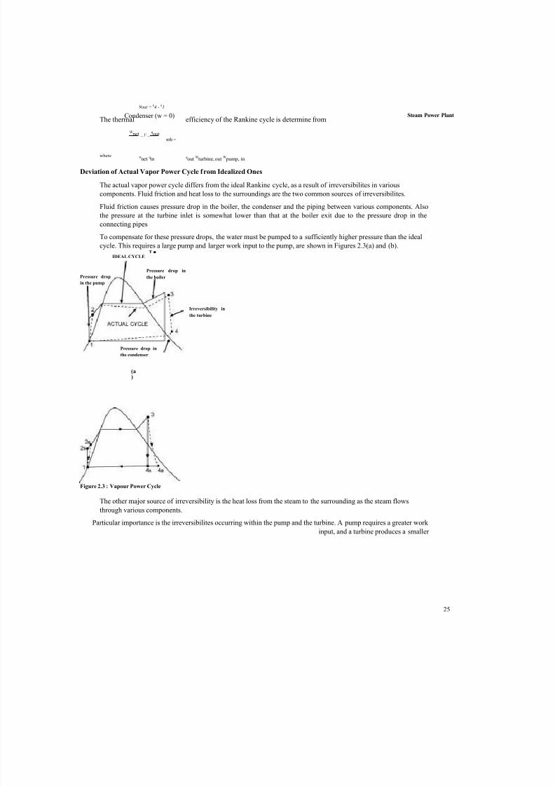
Deviation of Actual Vapor Power Cycle from Idealized Ones
The actual vapor power cycle differs from the ideal Rankine cycle, as a result of irreversibilites in various
components. Fluid friction and heat loss to the surroundings are the two common sources of irreversibilites.
Fluid friction causes pressure drop in the boiler, the condenser and the piping between various components. Also
the pressure at the turbine inlet is somewhat lower than that at the boiler exit due to the pressure drop in the
connecting pipes
To compensate for these pressure drops, the water must be pumped to a sufficiently higher pressure than the ideal
cycle. This requires a large pump and larger work input to the pump, are shown in Figures 2.3(a) and (b).T ■
The other major source of irreversibility is the heat loss from the steam to the surrounding as the steam flows
through various components.
Particular importance is the irreversibilites occurring within the pump and the turbine. A pump requires a greater work
input, and a turbine produces a smaller
IDEAL CYCLE
Pressure drop
in the pump
Pressure drop in
the boiler
Irreversibility in
the turbine
Pressure drop in
the condenser
(a)
Figure 2.3 : Vapour Power Cycle
nth =
7/27/2019 Thermal Power plant Unit-2-58.docx
http://slidepdf.com/reader/full/thermal-power-plant-unit-2-58docx 6/65
Power Plant Engineering
s
work output as a result of irreversibilties. Under the ideal condition the flow through these devices is isentropic.
The deviation of actual pumps and turbine from the isentropic ones can be accurately accounted by isentropic
efficiencies, define as :
How can We Increase the Efficiency of the Rankine cycle?
Than Rankine cycle efficiency can be increased by increasing average temperature at which heat is transferred to
the working fluid in the boiler or decreasing the average temperature at which heat is rejected from the working
fluid in the condenser. That is, the average fluid temperature should be as high as possible during heat addition and
as low as possible during heat rejection.
The three ways by which efficiency of the Rankine cycle can be increased are :
(a) Lowering the condenser pressure (Lowers Tlow, av ).
(b) Superheating the steam to high temperatures (Increases Thigh, av ).
(c) Increasing the boiler pressure (Increases Thigh, av ).
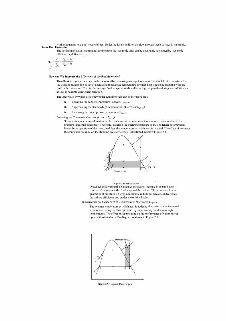
Lowering the Condenser Pressure (Lowers T [ow av )
Steam exists as a saturated mixture in the condenser at the saturation temperature corresponding to the
pressure inside the condenser. Therefore, lowering the operating pressure of the condenser automatically
lower the temperature of the steam, and thus the temperature at which heat is rejected. The effect of lowering
the condenser pressure on the Rankine cycle efficiency is illustrated in below Figure 2.4.T
Drawback of lowering the condenser pressure is increase in the moisture
content of the steam at the final stages of the turbine. The presence of large
quantities of moisture is highly undesirable in turbines because it decreases
the turbine efficiency and erodes the turbine blades.
Superheating the Steam to High Temperatures (Increases T high av )
The average temperature at which heat is added to the steam can be increased
without increasing the boiler pressure by superheating the steam to high
temperatures. The effect of superheating on the performance of vapor power
cycle is illustrated on a T-s diagram as shown in Figure 2.5.
„W a h3 - h4 a
nT ~ --------- —
-----------------ws h3 - h4 s
Increase in wnet
P'4 < P4
Figure 2.4 : Rankine Cycle
7/27/2019 Thermal Power plant Unit-2-58.docx
http://slidepdf.com/reader/full/thermal-power-plant-unit-2-58docx 7/65
27
Superheating the steam to higher temperatures has very desirable effect : ItSteam Power Plant
decreases the moisture content of the steam at the turbine exit as can be seen in T-s diagram as shown in
Figure 2.6.The temperature to which steam can be superheated is limited by metallurgical consideration.
Increasing the Boiler Pressure (Increases T high , av )
The average temperature during the heat addition process is to increase the
operating pressure of the boiler, which automatically raises the temperature at
which boiling take place. This, in turn, raises the average temperature at
which heat is added to the steam and thus raises the thermal efficiency of the
cycle.
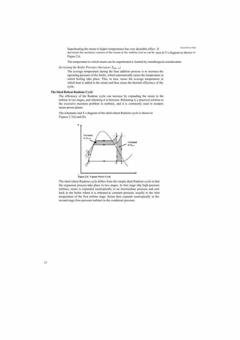
The Ideal Reheat Rankine Cycle
The efficiency of the Rankine cycle can increase by expanding the steam in the
turbine in two stages, and reheating it in between. Reheating is a practical solution to
the excessive moisture problem in turbines, and it is commonly used in modern
steam power plants.
The schematic and T-s diagram of the ideal reheat Rankine cycle is shown in
Figures 2.7(a) and (b).
The ideal reheat Rankine cycle differs from the simple ideal Rankine cycle in that
the expansion process take place in two stages. In first stage (the high-pressure
turbine), steam is expanded isentropically to an intermediate pressure and sent
back to the boiler where it is reheated at constant pressure, usually to the inlet
temperature of the first turbine stage. Steam then expands isentropically in the
second stage (low-pressure turbine) to the condenser pressure.
s Figure 2.6 : Vapour Power Cycle

7/27/2019 Thermal Power plant Unit-2-58.docx
http://slidepdf.com/reader/full/thermal-power-plant-unit-2-58docx 8/65
Power Plant Engineering
(b)
Figure 2.7 : Ideal Reheat Rankine Cycle Thus the total heat input and the total work output for a reheat cycle become :
qin
=^primary
+ qreheat
= (h3
— h2
) + (h5
— h4
)
wturbine, out
_ wturbine, I ̂
wturbine, II
_ (h3
— h4
)^
(h5
— h6
)
The Ideal Regenerative Rankine Cycle
As shown in Figure 2.8, T-s diagram for the Rankine cycle shows that heat transferred to the working fluid during
process 2-2' at a relatively low temperature. This lowers the average heat-addition temperature and thus the cycleefficiency.
To remedy this shortcoming, the temperature of the liquid leaving the pump (called feedwater) before it enters the
boiler need to be increased.
28
Condenser IPump
"
(a)
Reheating
High-pressure I turbine 3
I4
Low pressure
Low-
temperature
heat addition
Steam exiting
boiler
Figure 2.8 : Ideal Regenerative Rankine Cycle
s
7/27/2019 Thermal Power plant Unit-2-58.docx
http://slidepdf.com/reader/full/thermal-power-plant-unit-2-58docx 9/65
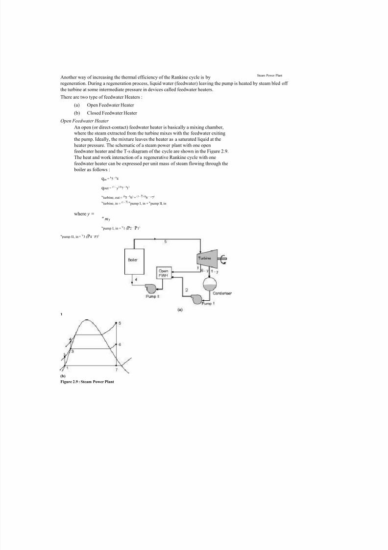
Another way of increasing the thermal efficiency of the Rankine cycle is bySteam Power Plant
regeneration. During a regeneration process, liquid water (feedwater) leaving the pump is heated by steam bled off
the turbine at some intermediate pressure in devices called feedwater heaters.
There are two type of feedwater Heaters :
(a) Open Feedwater Heater
(b) Closed Feedwater Heater
Open Feedwater Heater
An open (or direct-contact) feedwater heater is basically a mixing chamber,
where the steam extracted from the turbine mixes with the feedwater exiting
the pump. Ideally, the mixture leaves the heater as a saturated liquid at the
heater pressure. The schematic of a steam power plant with one open
feedwater heater and the T-s diagram of the cycle are shown in the Figure 2.9.
The heat and work interaction of a regenerative Rankine cycle with one
feedwater heater can be expressed per unit mass of steam flowing through the
boiler as follows :
qin =h5
- h4
qout = (1 - y) (h7 - h1)
wturbine, out =
(h5
- h6
)+
(1 - y) (h6
-^7
)
wturbine, in =
(1 - y) w pump I, in +
w pump II, in
where y = " m5
w pump I, in = V1 (P2 - P1)
w pump II, in =
V3 (P4
-P3
)
T
(b)
Figure 2.9 : Steam Power Plant

7/27/2019 Thermal Power plant Unit-2-58.docx
http://slidepdf.com/reader/full/thermal-power-plant-unit-2-58docx 10/65
Power Plant Engineering
30
The thermal efficiency of the Rankine cycle increases as a result of regeneration. This is
because regeneration raises the average temperature at which heat is transferred to the steam
in the boiler by raising the temperature of the water before it enters the boiler.
Closed Feedwater Heaters
Another type of feedwater heater used is steam power plants is the closed feedwater heater in which
heat is transferred from the extracted steam to the feedwater without any mixing taking place. The
two streams now can be at different pressure, since they do not mix. The schematic of a steam power
plant with one closed feedwater heater and the T-s diagram of the cycle are shown in Figure 2.10.
2.3 STEAM GENERATOR
Steam is an important medium of producing mechanical energy. Steam has the advantage that, it can be raised from
water which is available in abundance it does not react much with the materials of the equipment of power plant and
is stable at the temperature required in the plant. Steam is used to drive steam engines, steam turbines etc. Steam
power station is most suitable where coal is available in abundance.
Thermal electrical power generation is one of the major methods. Out of total power developed in India about 60%
is thermal. For a thermal power plant the range of pressure may vary from 10 kg/cm2 to super critical pressures andthe range of temperature may be from 250°C to 650°C.
T
(a)

7/27/2019 Thermal Power plant Unit-2-58.docx
http://slidepdf.com/reader/full/thermal-power-plant-unit-2-58docx 11/65
2.3.1 Essentials of Steam Power Plant Equipment
A steam power plant must have following equipment :
(a) A furnace to burn the fuel.
(b) Steam generator or boiler containing water. Heat generated in the furnace is
utilized to convert water into steam.
(c) Main power unit such as an engine or turbine to use the heat energy of steam
and perform work.
(d) Piping system to convey steam and water.
In addition to the above equipment the plant requires various auxiliaries and accessories depending upon the availability
of water, fuel and the service for which the plant is intended.
The flow sheet of a thermal power plant consists of the following four main circuits :
(a) Feed water and steam flow circuit.
(b) Coal and ash circuit.
(c) Air and gas circuit.
(d) Cooling water circuit.
A steam power plant using steam as working substance works basically on Rankine cycle.
Steam is generated in a boiler, expanded in the prime mover and condensed in the condenser and fed into the boiler
again.
Figure 2.11 shows a schematic arrangement of equipment of a steam power station. Coal received in coal storage yard of
power station is transferred in the furnace by coal handling unit. Heat produced due to burning of coal is utilized in
converting water contained in boiler drum into steam at suitable pressure and temperature. The steam generated is
passed through the superheater. Superheated steam then flows through the turbine. After doing work in the turbine the
pressure of steam is reduced. Steam leaving the turbine passes through the condenser which is maintained the low
pressure of steam at the exhaust of turbine. Steam pressure in the condenser depends upon flow rate and temperature of
cooling water and on effectiveness of air removal equipment. Water circulating through the condenser may be taken
from the various sources such as river,
lake or sea. If sufficient quantity of water is not available the hot water coming out of the condenser may be cooled incooling towers and circulated again through the condenser.
Bled steam taken from the turbine at suitable extraction points is sent to low pressure
and high pressure water heaters. 31
The different types of systems and components used in steam power plant are as
follows :
(a) High pressure boiler
(b) Prime mover
(c) Condensers and cooling towers
(d) Coal handling system
(e) Ash and dust handling system
(f) Draught system
(g) Feed water purification plant
(h) Pumping system
(i) Air preheater, economizer, super heater, feed heaters
Steam Power Plant

7/27/2019 Thermal Power plant Unit-2-58.docx
http://slidepdf.com/reader/full/thermal-power-plant-unit-2-58docx 12/65
Power Plant Engineering
32
3-phase supply
fO-High pressure
. (T) heater CondensateB°iler f eed''' extraction pumppump
Figure 2.11 : Steam Power Plant
Air taken from the atmosphere is first passed through the air pre-heater, where it is heated
by flue gases. The hot air then passes through the furnace. The flue gases after passing over
boiler and superheater tubes, flow through the dust collector and then through economiser,
air pre-heater and finally they are exhausted to the atmosphere through the chimney.
Steam condensing system consists of the following :
(a) Condenser
(b) Cooling water
(c) Cooling tower (d) Hot well
(e) Condenser cooling water pump
(f) Condensate air extraction pump
(g) Air extraction pump
(h) Boiler feed pump
(i) Make up water pump.
2.3.2 Classification
Boiler is an apparatus to produce steam. Thermal energy released by combustion of fuel is
transferred to water, which vaporizes and gets converted into steam at the desired
temperature and pressure.
The steam produced is used for :
(a) Producing mechanical work by expanding it in steam engine or steam
turbine.
(b) Heating the residential and industrial buildings.
(c) Performing certain processes in the sugar mills, chemical and textile
Turbine sxEsflxEEE generator
Low
presser
heaterCirculationwater pump
Cooling tower
River or canal ►

7/27/2019 Thermal Power plant Unit-2-58.docx
http://slidepdf.com/reader/full/thermal-power-plant-unit-2-58docx 13/65
industries.
Boiler is a closed vessel in which water is converted into steam by the application of heat.Usually boilers are coal or oil fired.

7/27/2019 Thermal Power plant Unit-2-58.docx
http://slidepdf.com/reader/full/thermal-power-plant-unit-2-58docx 14/65

7/27/2019 Thermal Power plant Unit-2-58.docx
http://slidepdf.com/reader/full/thermal-power-plant-unit-2-58docx 15/65
A boiler should fulfill the following requirements Steam Power Plant
(a) Safety : The boiler should be safe under operating conditions.
(b) Accessibility : The various parts of the boiler should be accessible for repair and maintenance.
(c) Capacity : The boiler should be capable of supplying steam according to the
requirements.
(d) Efficiency : To permit efficient operation, the boiler should be able to absorb
a maximum amount of heat produced due to burning of fuel in the furnace.
(e) It should be simple in construction and its maintenance cost should be low.
(f) Its initial cost should be low.
(g) The boiler should have no joints exposed to flames.
(h) The boiler should be capable of quick starting and loading.
2.3.3 Types of Boilers
The boilers can be classified according to the following criteria.
According to flow of water and hot gases :
(a) Water tube
(b) Fire tube.
In water tube boilers, water circulates through the tubes and hot products of combustion
flow over these tubes. In fire tube boiler the hot products of combustion pass through the
tubes, which are surrounded, by water. Fire tube boilers have low initial cost, and are more
compacts. But they are more likely to explosion, water volume is large and due to poor
circulation they cannot meet quickly the change in steam demand. For the same output the
outer shell of fire tube boilers is much larger than the shell of water-tube boiler. Water
tube boilers require less weight of metal for a given size, are less liable to explosion,
produce higher pressure, are accessible and can respond quickly to change in steam
demand. Tubes and drums of water-tube boilers are smaller than that of fire-tube boilers
and due to smaller size of drum higher pressure can be used easily. Water-tube boilers
require lesser floor space. The efficiency of water-tube boilers is more.
Water tube boilers are classified as follows :
Horizontal Straight Tube Boilers
(a) Longitudinal drum
(b) Cross-drum.
Bent Tube Boilers
(a) Two drum
(b) Three drum
(c) Low head three drum
(d) Four drum.
Cyclone Fired Boilers
Various advantages of water tube boilers are as follows :
(a) High pressure can be obtained.
(b) Heating surface is large. Therefore steam can be generated easily.
(c) Large heating surface can be obtained by use of large number of tubes.
(d) Because of high movement of water in the tubes the rate of heat transfer
becomes large resulting into a greater efficiency.

7/27/2019 Thermal Power plant Unit-2-58.docx
http://slidepdf.com/reader/full/thermal-power-plant-unit-2-58docx 16/65
Power Plant Engineering Fire tube boilers are classified as follows :
External Furnace
(a) Horizontal return tubular
(b) Short fire box
(c) Compact.
Internal Furnace
Horizontal Tubular
(a) Short firebox
(b) Locomotive
(c) Compact
(d) Scotch.
Vertical Tubular
(a) Straight vertical shell, vertical tube
(b) Cochran (vertical shell) horizontal tube.
Various advantages of fire tube boilers are as follows :
(a) Low cost
(b) Fluctuations of steam demand can be met easily
(c) It is compact in size.
According to position of furnace :
(a) Internally fired
(b) Externally fired
In internally fired boilers the grate combustion chamber are enclosed within the
boiler shell whereas in case of extremely fired boilers and furnace and grate are
separated from the boiler shell.
According to the position of principle axis :
(a) Vertical
(b) Horizontal
(c) Inclined.
According to application :
(a) Stationary
(b) Mobile, (Marine, Locomotive).
According to the circulating water :
(a) Natural circulation
(b) Forced circulation.
According to steam pressure :
(a) Low pressure
(b) Medium pressure
(c) Higher pressure.
2.3.4 Major Components and Their Functions
Economizer
The economizer is a feed water heater, deriving heat from the flue gases. The
justifiable cost of the economizer depends on the total gain in efficiency. In turn this
depends on the flue gas temperature leaving the boiler and the feed water inlet
temperature. A typical return bend type economizer is shown in the Figure 2.11.
7/27/2019 Thermal Power plant Unit-2-58.docx
http://slidepdf.com/reader/full/thermal-power-plant-unit-2-58docx 17/65
Air Pre-heater Steam Power Plant The flue gases coming out of the economizer is used to preheat the air before
supplying it to the combustion chamber. An increase in air temperature of 20 degrees
can be achieved by this method. The pre heated air is used for combustion and also todry the crushed coal before pulverizing.
Soot Blowers
The fuel used in thermal power plants causes soot and this is deposited on the boiler
tubes, economizer tubes, air pre heaters, etc. This drastically reduces the amount of
heat transfer of the heat exchangers. Soot blowers control the formation of soot and
reduce its corrosive effects. The types of soot blowers are fixed type,
which may be further classified into lane type and mass type depending upon the type
of spray and nozzle used. The other type of soot blower is the retractable soot blower.
The advantages are that they are placed far away from the high temperature zone, they
concentrate the cleaning through a single large nozzle rather than many small nozzles
and there is no concern of nozzle arrangement with respect to the boiler tubes.Condenser
The use of a condenser in a power plant is to improve the efficiency of the power plant
by decreasing the exhaust pressure of the steam below atmosphere. Another advantage
of the condenser is that the steam condensed may be recovered to provide a source of
good pure feed water to the boiler and reduce the water softening capacity to a
considerable extent. A condenser is one of the essential components of a power plant.
Cooling Tower
The importance of the cooling tower is felt when the cooling water from the condenser
has to be cooled. The cooling water after condensing the steam becomes hot and it has
to be cooled as it belongs to a closed system. The Cooling towers do the job of
decreasing the temperature of the cooling water after condensing the steam in the
condenser.
The type of cooling tower used in the Columbia Power Plant was an Inline Induced
Draft Cross Flow Tower. This tower provides a horizontal air flow as the water falls
down the tower in the form of small droplets. The fan centered at the top of units
draws air through two cells that are paired to a suction chamber partitioned beneath the
fan. The outstanding feature of this tower is lower air static pressure loss as there is
less resistance to air flow. The evaporation and effective cooling of air is greater when
the air outside is warmer and dryer than when it is cold and already saturated.
SuperheaterThe superheater consists of a superheater header and superheater elements. Steam
from the main steam pipe arrives at the saturated steam chamber of the superheater
header and is fed into the superheater elements. Superheated steam arrives back at the
superheated steam chamber of the superheater header and is fed into the steam pipe to
the cylinders. Superheated steam is more expansive.Reheater
The reheater functions similar to the superheater in that it serves to elevate the steam
temperature. Primary steam is supplied to the high pressure turbine. After passing
through the high pressure turbine, the steam is returned to the steam generator for
reheating (in a reheater) after which it is sent to the low pressure turbine. A second
reheat cycle may also be provided.
SAQ 1
(a) Describe the various types of power cycles.
(b) What is steam generator? Describe the components of steam power plant.
(c) What is a boiler? Discuss about different types of boilers, its componentsand functions. «

7/27/2019 Thermal Power plant Unit-2-58.docx
http://slidepdf.com/reader/full/thermal-power-plant-unit-2-58docx 18/65
36
Power Plant En
gin
eerin
g2.4 SUPER HEATER
One of the most important accessories of a boiler is a super heater. It effects
improvement and economy in the following ways :
• The super heater increases the capacity of the plant.
• Eliminates corrosion of the steam turbine.
• Reduces steam consumption of the steam turbine.
Types of Super Heater
• Plate Super heaters.
• Pendant Super heaters.
• Radiant Super heaters.
• Final Super heaters.
2.4.1 Steam Temperature ControlThe nominal control of reheat steam temperature is by tilting the burners. The super
heater steam temperature is controlled by spraying water.
Other control methods that are according to the need and design are :
(a) Excess Air Control
(b) Flue Gas Recirculation
(c) Gas by-pass Control
(d) Control of Combination Superheaters
(e) Adjustable Burner Control Excess Air Control
The steam outlet temperature of a convection superheater may be increased at partial
load by increasing the excess air supply. The reduced gas temperature decreases the
furnace heat absorption for the same steam production. The increased gas mass flowwith its increased total heat content serves to increase the degree of superheat.
Radiant superheater
Convection
superheater
Economizer
Combustion
zone
Tempering air
(alternate)
Figure 2.12 : Superheat control by increased excess air

7/27/2019 Thermal Power plant Unit-2-58.docx
http://slidepdf.com/reader/full/thermal-power-plant-unit-2-58docx 19/65
37
Flue Gas Recirculation
The recirculation of some percentage of the combustion gases serves to control steam
temperature in the same manner as does an increase in excess air. By introducing thehot gases below the combustion zone, relatively high efficiency may be maintained.
Gas By-pass Control
The boiler convection banks can be arranged in such a manner that portion of the
gases can be by-passed around the superheater elements. The superheater is oversized
so that it will produce the required degree of superheat at partial load
Figure 2.13 : Superheat Control by Flue GasRecirculation
Steam Power Plant

7/27/2019 Thermal Power plant Unit-2-58.docx
http://slidepdf.com/reader/full/thermal-power-plant-unit-2-58docx 20/65
Power Plant En
gineer
ing Control of Combination Superheaters
The control of combination radiant-convection superheaters is relatively simple
because of their compensating characteristics. An increase in excess air reduces the
radiant heat transfer but increases the convection heat transfer. The reduction inexcess air has the opposite effect. Thus the combination superheaters can be
operated over the entire control range without additional equipment.
Adjustable Burner Control
With a multiple burner furnace it is possible to distribute the burners over a
considerable burner wall height. This control is obtained by selective firing.
2.5 FEED WATER HEATER
Low pressure feed water heaters are used in the condensate system between thecondensate pump discharge and boiler feed pumps, and utilize low pressure turbine
extraction or auxiliary turbine exhaust steam for heating the condensate.
High pressure feed water heaters are used in the feed water system between the boiler feed
pump discharge and the boiler, and utilize high pressure turbine extraction steam for
heating the feed water. The condensate or feed water temperature increase for each feed
water heater will be in the range of 28 to 56 degrees C with the actual value determined by
turbine manufacturer's stage location of steam extraction nozzles. Depending on turbine
size, some turbines offer alternate number of extraction nozzles with usually a choice of
using the highest pressure extraction nozzle. The selection, in this case, of the total number
of feed water heaters to use should be based on economic evaluation.
Low Pressure Heater(s)
Use one or more low pressure feed water heaters to raise the temperature of condensate
from condensate pump discharge temperature to the de-aerator inlet temperature. The
heater drains are cascaded from the higher pressure heater to the next lower pressure
heater with the lowest pressure heater draining to the condenser.
High Pressure Heater(s)
Use one or more high pressure feed water heaters to raise the temperature of feed
water from de-aerator outlet temperature to the required boiler economizer inlet
Tiltable furnace may be adjusted to shift the position of the combustion zone. Convection

7/27/2019 Thermal Power plant Unit-2-58.docx
http://slidepdf.com/reader/full/thermal-power-plant-unit-2-58docx 21/65
Steam Power Plant
39
Low
pressure ---------- Generator
1Boiler
<2>
Feed
water
heater
(e>
temperature. The heater drains are cascaded from heater to heater, back to the de-
aerator in a fashion similar to the heater drain system for the low pressure heaters.
2.5.1 Advantages
(a) Fuel economy.
(b) Longer life of the boiler.
(c) Increase in steaming capacity.
A feedwater heater is a power plant component used to pre-heat water delivered to a steam
generating boiler. Preheating the feedwater reduces the irreversibilities involved in steam
generation and therefore improves the thermodynamic efficiency of the system. This reduces
plant operating costs and also helps to avoid thermal shock to the boiler metal when the
feedwater is introduced back into the steam cycle.
In a steam power plant (usually modeled as a modified Rankine cycle), feedwater heaters
allow the feedwater to be brought up to the saturation temperature very gradually. This
minimizes the inevitable irreversibilities associated with heat transfer to the working fluid
(water).
2.5.2 Cycle Discussion and Explanation
It should be noted that the energy used to heat the feedwater is usually derived from
steam extracted between the stages of the steam turbine. Therefore, the steam that would
be used to perform expansion work in the turbine is not utilized for that purpose. The
percentage of the total cycle steam mass flow used for the feedwater heater must be
carefully optimized for maximum power plant thermal efficiency since increasing this
causes a decrease in turbine power output.
FP1 = Feed pump 1 FP2 = Feed
pump 2 HPT = High pressure
turbine LPT = Low Pressure
turbine
Figure 2.16 : Rankine Cycle with Two Steam Turbines and a Single Open Feedwater Heater
r
u
t
ep
Entropy
High
turbine pressure
turbine
aFeed pump 1
Feed pump 2

7/27/2019 Thermal Power plant Unit-2-58.docx
http://slidepdf.com/reader/full/thermal-power-plant-unit-2-58docx 22/65
40
Power Plant Engineering Feedwater heaters can also be open and closed heat exchangers. An open feedwater
heater is merely a direct-contact heat exchanger in which extracted steam is allowed to mix
with the feedwater. This kind of heater will normally require a feed pump at both the feedinlet and outlet since the pressure in the heater is between the boiler pressure and the
condenser pressure. A deaerator is a special case of the open feedwater heater which is
specifically designed to remove non-condensable gases from the feedwater.
Closed feedwater heaters are typically shell and tube heat exchangers where the feedwater
passes throughout the tubes and is heated by turbine extraction steam. These do not require
separate pumps before and after the heater to boost the feedwater to the pressure of the
extracted steam as with an open heater. However, the extracted steam must then be throttled
to the condenser pressure.
Many power plants incorporate a number of feedwater heaters and may use both open and
closed components.
Feedwater heaters are used in both fossil- and nuclear-fueled power plants. Smaller versions
have also been installed on steam locomotives, portable engines and stationary engines. An
economiser serves a similar purpose to a feedwater heater, but is technically different.
Instead of using actual cycle steam for heating, it uses the lowest-temperature flue gas fromthe furnace to heat the water before it enters the boiler proper. This allows for the heat
transfer between the furnace and the feedwater occurring across a smaller average
temperature gradient. System efficiency is therefore further increased when viewed with
respect to actual energy content of the fuel.
2.5.3 Air Preheaters
An air preheater or air heater is a general term to describe any device designed to heat air
before another process (for example, combustion in a boiler) with the primary objective of
increasing the thermal efficiency of the process. They may be used alone or to replace a
recuperative heat system or to replace a steam coil.
In particular, this article describes the combustion air preheaters used in large boilers found
in thermal power stations producing electric power from e.g. fossil fuels, biomasses or waste
The purpose of the air preheater is to recover the heat from the boiler flue gas which
increases the thermal efficiency of the boiler by reducing the useful heat lost in the flue gas.As a consequence, the flue gases are also sent to the flue gas stack (or chimney) at a lower
temperature, allowing simplified design of the ducting and the flue gas stack. It also allows
control over the temperature of gases leaving the stack (to meet emissions regulations, for
example).
Figure 2.17 : Coal-fired Power Plant Steam Generator Highlighting the Air Pre-eater Location
(Radiant Section Tubing is Not Shown)
7/27/2019 Thermal Power plant Unit-2-58.docx
http://slidepdf.com/reader/full/thermal-power-plant-unit-2-58docx 23/65
Types Steam Power Plant There are two types of air preheaters for use in steam generators in thermal power stations : One is a tubular type
built into the boiler flue gas ducting, and the other is a regenerative air preheater. These may be arranged so the
gas flows horizontally or vertically across the axis of rotation.Tubular Type
Construction Features
Tubular preheaters consist of straight tube bundles which pass through the outlet ducting of the boiler and
open at each end outside of the ducting.
Inside the ducting, the hot furnace gases pass around the preheater tubes,
transferring heat from the exhaust gas to the air inside the preheater.
Ambient air is forced by a fan through ducting at one end of the preheater tubes and at other end the
heated air from inside of the tubes emerges into another set of ducting, which carries it to the boiler
furnace for combustion.Problems
The tubular preheater ductings for cold and hot air require more space and structural supports than a rotating
preheater design. Further, due to dust-laden abrasive flue gases, the tubes outside the ducting wear out faster on
the side facing the gas current. Many advances have been made to eliminate this problem such as the use of
ceramic and hardened steel.
Many new circulating fluidized bed (CFB) and bubbling fluidized bed (BFB)steam generators are currently incorporating tubular air heaters offering an advantage with regards to the moving
parts of a rotary type.Dew Point Corrosion
Dew point corrosion occurs for a variety of reasons. The type of fuel used, its sulfur content and moisture
content are contributing factors. However, by far the most significant cause of dew point corrosion is the metal
temperature of the tubes. If the metal temperature within the tubes drops below the acid saturation temperature,
usually at between 88°C and 110°C, but sometimes at temperatures as high as 127°C, then the risk of dew point
corrosion damage becomes considerable.Regenerative Air Pre-heaters
There are two types of regenerative air pre-heaters: the rotating-plate regenerative air preheaters and the
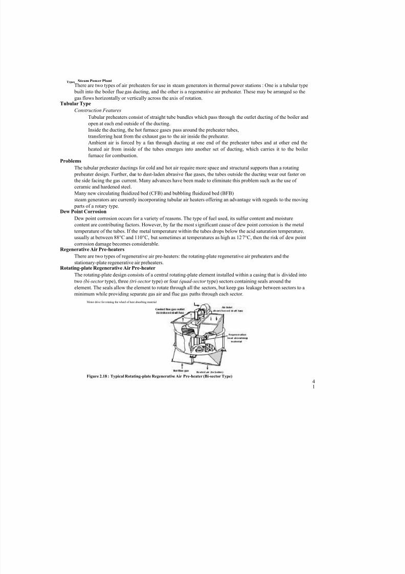
stationary-plate regenerative air preheaters.Rotating-plate Regenerative Air Pre-heater
The rotating-plate design consists of a central rotating-plate element installed within a casing that is divided into
two (bi-sector type), three (tri-sector type) or four (quad-sector type) sectors containing seals around the
element. The seals allow the element to rotate through all the sectors, but keep gas leakage between sectors to a
minimum while providing separate gas air and flue gas paths through each sector.
41
Motor drive for rotating the wheel of heat absorbing material
Figure 2.18 : Typical Rotating-plate Regenerative Air Pre-heater (Bi-sector Type)
7/27/2019 Thermal Power plant Unit-2-58.docx
http://slidepdf.com/reader/full/thermal-power-plant-unit-2-58docx 24/65
42
Power Plant Engineering Tri-sector types are the most common in modern power generation facilities. In
the tri-sector design, the largest sector is connected to the boiler hot gas outlet. The
hot exhaust gas flows over the central element, transferring some of its heat to the
element, and is then ducted away for further treatment in dust collectors and other equipment before being expelled from the flue gas stack. The second,
smaller sector, is fed with ambient air by a fan, which passes over the heated element
as it rotates into the sector, and is heated before being carried to the boiler furnace for
combustion. The third sector is the smallest one and it heats air which is routed into
the pulverizers and used to carry the coal-air mixture to coal boiler burners. Thus, the
total air heated in the air preheater provides: heating air to remove the moisture from
the pulverised coal dust, carrier air for transporting the pulverised coal to the boiler
burners and the primary air for combustion.
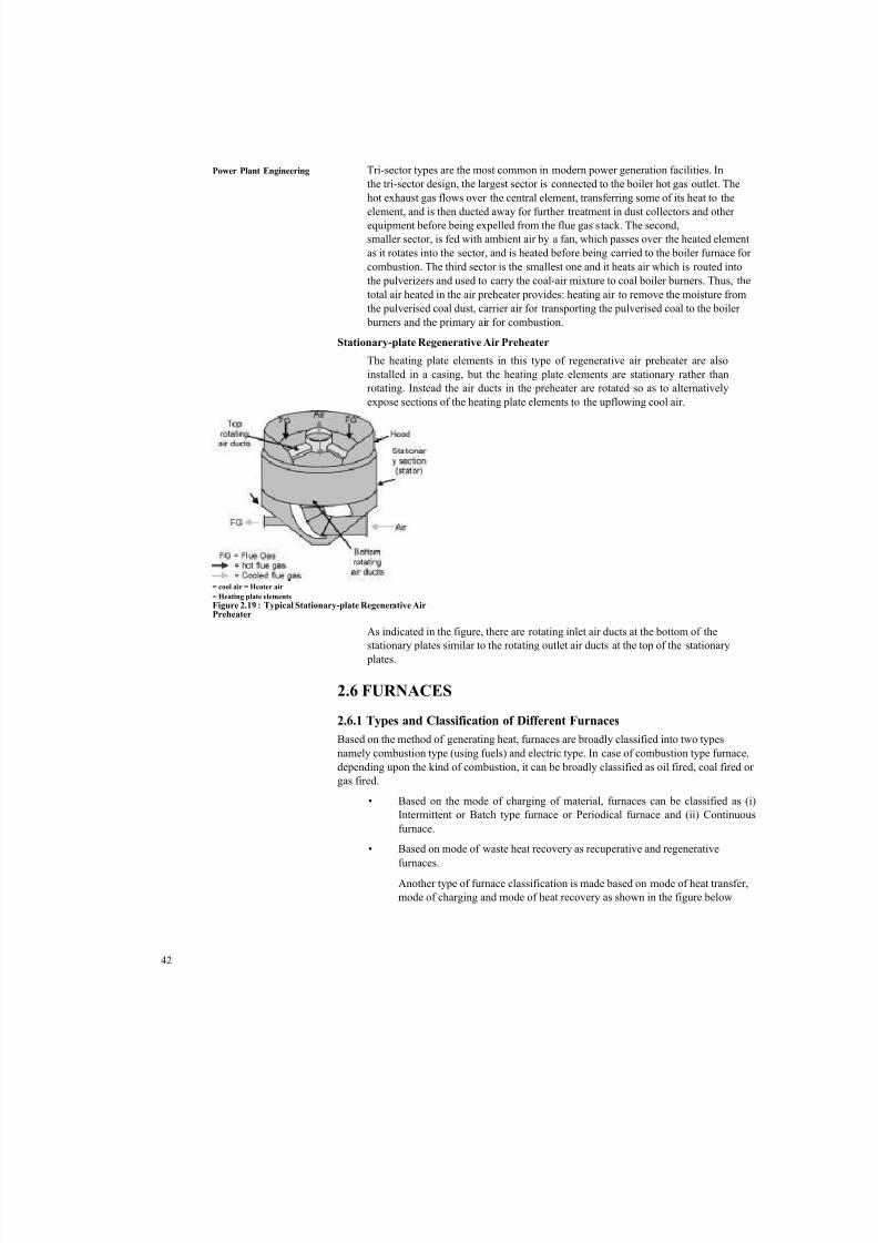
Stationary-plate Regenerative Air Preheater
The heating plate elements in this type of regenerative air preheater are also
installed in a casing, but the heating plate elements are stationary rather than
rotating. Instead the air ducts in the preheater are rotated so as to alternatively
expose sections of the heating plate elements to the upflowing cool air.
As indicated in the figure, there are rotating inlet air ducts at the bottom of thestationary plates similar to the rotating outlet air ducts at the top of the stationary
plates.
2.6 FURNACES
2.6.1 Types and Classification of Different Furnaces
Based on the method of generating heat, furnaces are broadly classified into two types
namely combustion type (using fuels) and electric type. In case of combustion type furnace,
depending upon the kind of combustion, it can be broadly classified as oil fired, coal fired or
gas fired.
• Based on the mode of charging of material, furnaces can be classified as (i)
Intermittent or Batch type furnace or Periodical furnace and (ii) Continuous
furnace.
• Based on mode of waste heat recovery as recuperative and regenerative
furnaces.
Another type of furnace classification is made based on mode of heat transfer,
mode of charging and mode of heat recovery as shown in the figure below
= cool air = Heater air
= Heating plate elements
Figure 2.19 : Typical Stationary-plate Regenerative AirPreheater

7/27/2019 Thermal Power plant Unit-2-58.docx
http://slidepdf.com/reader/full/thermal-power-plant-unit-2-58docx 25/65
2.6.2 Characteristics of an Efficient Furnace
Furnace should be designed so that in a given time, as much of material as possible can be heated to a uniform
temperature as possible with the least possible fuel and labour. To achieve this, the following parameters can be
considered.
• Determination of the quantity of heat to be imparted to the material or charge.
• Liberation of sufficient heat within the furnace to heat the stock and overcome all heat losses.
• Transfer of available part of that heat from the furnace gases to the surface of the heating stock.
• Equalization of the temperature within the stock.
• Reduction of heat losses from the furnace to the minimum possible extent.
2.6.3 Pulverised Coal Systems
Pulverised coal firing is done by two systems :
(a) Unit System or Direct System.
(b) Bin or Central System.
Unit System
In this system the raw coal from the coal bunker drops on to the feeder
Figure 2.20 : Furnace Classification
Hot Air
Figure 2.21 : Unit or Direct System
7/27/2019 Thermal Power plant Unit-2-58.docx
http://slidepdf.com/reader/full/thermal-power-plant-unit-2-58docx 26/65
Power Plant Engineering Hot air is passed through coal in the feeder to dry the coal. The coal is then transferred to the pulverising mill
where it is pulverised. Primary air is supplied to the mill, by the fan. The mixture of pulverised coal and
primary air then flows to burner where secondary air is added. The unit system is so called from the fact that
each burner or a burner group and pulveriser constitutes a unit.
Advantages
(a) The system is simple and cheaper than the central system.
(b) There is direct control of combustion from the pulverising mill.
(c) Coal transportation system is simple.
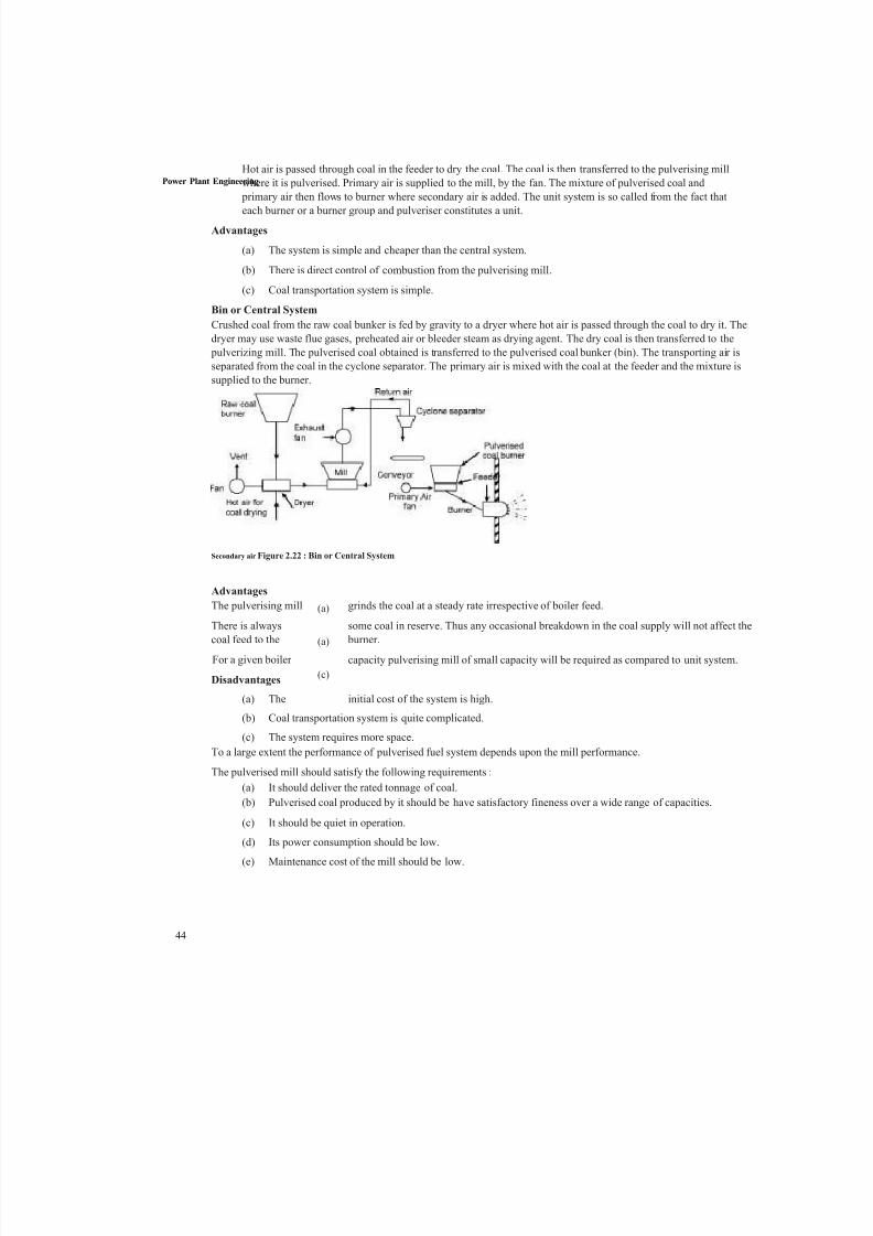
Bin or Central System
Crushed coal from the raw coal bunker is fed by gravity to a dryer where hot air is passed through the coal to dry it. The
dryer may use waste flue gases, preheated air or bleeder steam as drying agent. The dry coal is then transferred to the
pulverizing mill. The pulverised coal obtained is transferred to the pulverised coal bunker (bin). The transporting air is
separated from the coal in the cyclone separator. The primary air is mixed with the coal at the feeder and the mixture is
supplied to the burner.
Advantages
The pulverising mill grinds the coal at a steady rate irrespective of boiler feed.
There is always some coal in reserve. Thus any occasional breakdown in the coal supply will not affect thecoal feed to the burner.
For a given boiler capacity pulverising mill of small capacity will be required as compared to unit system.
Disadvantages
(a) The initial cost of the system is high.
(b) Coal transportation system is quite complicated.
(c) The system requires more space.
To a large extent the performance of pulverised fuel system depends upon the mill performance.
The pulverised mill should satisfy the following requirements :
(a) It should deliver the rated tonnage of coal.
(b) Pulverised coal produced by it should be have satisfactory fineness over a wide range of capacities.
(c) It should be quiet in operation.
(d) Its power consumption should be low.
(e) Maintenance cost of the mill should be low.
Secondary air Figure 2.22 : Bin or Central System
(a)
(a)
(c)
44

7/27/2019 Thermal Power plant Unit-2-58.docx
http://slidepdf.com/reader/full/thermal-power-plant-unit-2-58docx 27/65
Steam Power Plant
45
Figure 2.23 : Equipment for Central and Unit System
2.6.4 Draft System
Most boilers now depend on mechanical draft equipment rather than natural draft. This is because natural draft is subject
to outside air conditions and temperature of flue gases leaving the furnace, as well as the chimney height. All these
factors make proper draft hard to attain and therefore make mechanical draft equipment much more economical.
There are three types of mechanical draft :
Induced Draft
This is obtained one of three ways, the first being the "stack effect" of a heated chimney, in which the flue gasis less dense than the ambient air surrounding the boiler. The denser column of ambient air forces combustion
air into and through the boiler. The second method is through use of a steam jet. The steam jet oriented in the
direction of flue gas flow induces flue gasses into the stack and allows for a greater flue gas velocity increasing
the overall draft in the furnace. This method was common on steam driven locomotives which could not have
tall chimneys. The third method is by simply using an induced draft fan (ID fan) which removes flue gases
from the furnace and forces the exhaust gas up the stack. Almost all induced draft furnaces operate with a
slightly negative pressure.
Forced Draft
Draft is obtained by forcing air into the furnace by means of a fan (FD fan) and ductwork. Air is often passed
through an air heater; which, as the name suggests, heats the air going into the furnace in order to increase the
overall efficiency of the boiler. Dampers are used to control the quantity of air admitted to the furnace. Forced
draft furnaces usually have a positive pressure.
Balanced Draft
Balanced draft is obtained through use of both induced and forced draft. This is more common with larger boilerswhere the flue gases have to travel a long
Figure 2.23 shows the equipments for unit and central system of pulverised coal handling plant.

7/27/2019 Thermal Power plant Unit-2-58.docx
http://slidepdf.com/reader/full/thermal-power-plant-unit-2-58docx 28/65
Power Plant Engineering
46
distance through many boiler passes. The induced draft fan works in conjunction with the forced draft fan allowing the
furnace pressure to be maintained slightly below atmospheric.
2.6.5 High Pressure BoilersIn all modern power plants, high pressure boilers (> 100 bar) are universally used as they
offer the following advantages. In order to obtain efficient operation and high capacity,
forced circulation of water through boiler tubes is found helpful. Some special types of
boilers operating at super critical pressures and using forced circulations are described in
this chapter.
(a) The efficiency and the capacity of the plant can be increased as reduced
quantity of steam is required for the same power generation if high pressure
steam is used.
(b) The forced circulation of water through boiler tubes provides freedom in the
arrangement of furnace and water walls, in addition to the reduction in the heat
exchange area.
(c) The tendency of scale formation is reduced due to high velocity of water.
(d) The danger of overheating is reduced as all the parts are uniformly heated.
(e) The differential expansion is reduced due to uniform temperature and this
reduces the possibility of gas and air leakages.
(f) Some special types of high pressure supercritical boilers are described in this
chapter.
2.6.6 LA MONT Boiler
A forced circulation boiler was first introduced in 1925 by La Mont. The arrangement of
water circulation and different components are shown in the figure. The feed water from hot
well is supplied to a storage and separating drum (boiler) through the economizer. Most of
the sensible heat is supplied to the feed water passing through the economizer. A pump
circulates the water at a rate 8 to 10 times the mass of steam evaporated. This water is
circulated through the evaporator tubes and the part of the vapour is separated in the
separator drum. The large quantity of water circulated (10 times that of evaporation)
prevents the tubes from being overheated.Chimney t
The centrifugal pump delivers the water to the headers at a pressure of 2.5 bar above the
drum pressure. The distribution headers distribute the water through the nozzle into the
evaporator. The steam separated in the boiler is further passed through the super-heater.
Fan
Air preheater
Ci rculating'Pump Distributing
header
Economise
Heater
Main steam
Evaporator
(convective)
Preheated
Evaporato
r (radiant)
Figure 2.24 : LA MONT Boiler

7/27/2019 Thermal Power plant Unit-2-58.docx
http://slidepdf.com/reader/full/thermal-power-plant-unit-2-58docx 29/65
47
Secure a uniform flow of feed water through each of the parallel boiler circuits a chokeSteam P
°wer Plant
is fitted entrance to each circuit. These boilers have been built to generate 45 to 50 tonnes of superheated steam at a
pressure of 120 bars and temperature of 500°C.
Recently forced circulation has been introduced in large capacity power
2.6.7 Benson Boiler
The main difficulty experienced in the La Mont boiler is the formation and attachment of
bubbles on the inner surfaces of the heating tubes. The attached bubbles reduce the heat
flow and steam generation as it offers higher thermal resistance compared to water film :
(a) If the boiler pressure was raised to critical pressure (225 atm), the steam and
water would have the same density and therefore the danger of bubble
formation can be completely avoided.
(b) Natural circulation boilers require expansion joints but these are not required
for Benson as the pipes are welded. The erection of Benson boiler is easier
and quicker as all the parts are welded at site and workshop job of tube
expansion is altogether avoided.
(c) The transport of Benson boiler parts is easy as no drums are required and
majority of the parts are carried to the site without pre-assembly.
(d) The Benson boiler can be erected in a comparatively smaller floor area. The
space problem does not control the size of Benson boiler used.
(e) The furnace walls of the boiler can be more efficiently protected by using
small diameter and close pitched tubes.
(f) The superheater in the Benson boiler is an integral part of forced circulation
system, therefore no special starting arrangement for superheater is required.
(g) The Benson boiler can be started very quickly because of welded joints.
(h) The Benson boiler can be operated most economically by varying the
temperature and pres- sure at partial loads and overloads. The desired
temperature can also be maintained constant at any pressure.
(i) Sudden fall of demand creates circulation problems due to bubble formation
in the natural circulation boiler which never occurs in Benson boiler. This
feature of insensitiveness to load fluctuations makes it more suitable for grid
power station as it has better adaptive capacity to meet sudden loadfluctuations.
(j) The blow-down losses of Benson boiler are hardly 4% of natural circulation
boilers of same capacity.
(k) Explosion hazards are not at all severe as it consists of only tubes of small
diameter and has very little storage capacity compared to drum type boiler.
During starting, the water is passed through the economiser, evaporator, superheater and back to the feed line via starting
valve.
During starting, first circulating pumps are started and then the burners are started to avoid the overheating of evaporator
and superheater tubes.
2.6.8 Loeffler Boiler
The major difficulty experienced in Benson boiler is the deposition of salt and sediment on
the inner surfaces of the water tubes. The deposition reduced the heat transfer and
ultimately the generating capacity. This further increased the danger of overheating the
tubes due to salt deposition as it has high thermal resistance. The difficulty was solved inLoffler boiler by preventing the flow of water into the boiler tubes. Most of the steam is
generated outside from the feed water using part of the superheated steam coming-out from
the boiler.

7/27/2019 Thermal Power plant Unit-2-58.docx
http://slidepdf.com/reader/full/thermal-power-plant-unit-2-58docx 30/65
Power Plant Eng
ineering The pressure feed pump draws the water through the economizer and delivers it into the
evaporator drum. About 65% of the steam coming out of super heater is passed through the
evaporator drum in order to evaporate the feed water coming from economizer.
The steam circulating pump draws the saturated steam from the evaporator drum and is passed
through the radiant superheater and then convective superheater. About 35% of the steam
coming out from the superheater is supplied to the H.P. steam turbine. The steam coming out
from H.P. turbine is passed through reheater before supplying to L.P. turbine. The amount of
steam generated in the evaporator drum is equal to the steam tapped (65%) from the
superheater. The nozzles which distribute the superheated steam through the water into the
evaporator drum are of special design to avoid priming and noise.
This boiler can carry higher salt concentration than any other type and is more compact than
indirectly heated boilers having natural circulation. These qualities fit it for land or sea
transport power generation. Loffler boilers with generating capacity of 94.5 tones/hr and
operating at 140 bar have already been commissioned.
2.6.9 SCHMIDT-HARTMANN Boiler
The operation of the boiler is similar to an electric transformer. Two pressures are used to
affect an interchange of energy. In the primary circuit, the steam at 100 bar is produced fromdistilled water. This steam is passed through a submerged heating coil which is located in an
evaporator drum. The high pressure steam in this coil possesses sufficient thermal potential and
steam at 60 bars with a heat transfer rate of 2.5 kW/m2-°C is generated in the evaporator drum.
The steam produced in the evporator drums from impure water is further passed through the
superheater and then supplied to the prime-mover. The high pressure condensate formed in the
sub- merged heating coil is circulated through a low pressure feed heater on its way to raise the
feed water temperature to its saturation temperature. Therefore, only latent heat is supplied in
the evaporator drum. Natural circulation is used in the primary circuit and this is sufficient to
effect the desired rate of heat transfer and to overcome the thermo-siphon head of about 2 m to
10 m. In normal circumstances, the replenishment of distilled water in the primary circuit is not
required as every care is taken in design and construction to prevent leakage. But as a
safeguard against leakage, a pressure gauge and safety valve are fitted in the circuit.
2.6.10 VELOX-Boiler
When the gas velocity exceeds the sound-velocity, the heat is transferred from the gas at amuch higher rate than rates achieved with sub-sonic flow. The advantages of this theory are
taken to obtain the large heat transfer from a smaller surface area in this boiler. Air is
compressed to 2.5 bars with the help of a compressor run by gas turbine before supplying to
the combustion chamber to get the supersonic velocity of the gases passing through the
combustion chamber and gas tubes and high heat release rates. The burned gases in the
combustion chamber are passed through the annulus of the tubes. The heat is transferred from
gases to water while passing through the annulus to generate the steam. The mixture of water
and steam thus formed then passes into a separator which is so designed that the mixture enters
with a spiral flow. The centrifugal force thus produced causes the heavier water particles to be
thrown outward on the walls. This effect separates the steam from water. The separated steam
is further passed to superheater and then supplied to the prime-mover. The water removed from
steam in the separator is again passed into the water tubes with the help of a pump.
The gases coming out from the annulus at the top are further passed over the superheater where
its heat is used-for superheating the steam. The gases coming out of superheater are used to run
a gas turbine as they carry sufficient kinetic energy. The power output of the gas turbine isused to run the air-compressor. The exhaust gases coming out from the gas turbine are passed
through the economiser to utilize the remaining heat of the gases. The extra power required to
run the compressor is supplied with the help of electric

7/27/2019 Thermal Power plant Unit-2-58.docx
http://slidepdf.com/reader/full/thermal-power-plant-unit-2-58docx 31/65
motor. Feed water of 10 to 20 times the weight of steam generated is circulated through the tubes with the help of
water circulating pump. This prevents the overheating of metal walls.
2.7 ENERGY PERFORMANCE ASSESSMENT OF BOILERS
Performance of the boiler, like efficiency and evaporation ratio reduces with time, due to poor combustion, heat transfer
fouling and poor operation and maintenance.
Deterioration of fuel quality and water quality also leads to poor performance of boiler. Efficiency testing helps us to
find out how far the boiler efficiency drifts away from the best efficiency. Any observed abnormal deviations could
therefore be investigated to pinpoint the problem area for necessary corrective action. Hence it is necessary to find out
the current level of efficiency for performance evaluation, which is a pre requisite for energy conservation action in
industry.
Purpose of the Performance Test
• To find out the efficiency of the boiler
• To find out the Evaporation ratio
The purpose of the performance test is to determine actual performance and efficiency of the boiler and
compare it with design values or norms. It is an indicator for tracking day-to-day and season-to-seasonvariations in boiler efficiency and energy efficiency improvements
Performance Terms and Definitions
(a) Boiler Efficiency, ^ =Heat output
x 100Heat input
_ Heat in steam output (kCals) ^ Ari Heat in fuel input (kCals)
^ . Quantity of steam generation(b) Evaporation Ratio = ------------------------------------------
Quantity of fuel consumption
Scope
The procedure describes routine test for both oil fired and solid fuel fired boilers using coal, agro residues etc.
Only those observations and measurements need to be made which can be readily applied and is necessary to
attain the purpose of the test.
2.7.1 Reference Standards
British standards, BS845 : 1987
The British Standard BS845: 1987 describes the methods and conditions under which a boiler should be tested to
determine its efficiency. For the testing to be done, the boiler should be operated under steady load conditions
(generally full load) for a period of one hour after which readings would be taken during the next hour of steady
operation to enable the efficiency to be calculated.
The efficiency of a boiler is quoted as the % of useful heat available, expressed as a percentage of the total energy
potentially available by burning the fuel. This is expressed on the basis of gross calorific value (GCV).
This deals with the complete heat balance and it has two parts :
(a) Part one deals with standard boilers, where the indirect method is specified.
Steam Power Plant
7/27/2019 Thermal Power plant Unit-2-58.docx
http://slidepdf.com/reader/full/thermal-power-plant-unit-2-58docx 32/65
Power Plant Engineering (b) Part two deals with complex plant where there are many channels of heat flow. In this case, both the
direct and indirect methods are applicable, in whole or in part.
ASME Standard : PTC-4-1 Power Test Code for Steam Generating Units
This consists of
(c) Part One : Direct method (also called as Input -output method).
(d) Part Two : Indirect method (also called as Heat loss method)
IS 8753 : Indian Standard for Boiler Efficiency Testing
Most standards for computation of boiler efficiency, including IS 8753 and BS845 are designed for spot
measurement of boiler efficiency. Invariably, all these standards do not include blow down as a loss in the
efficiency determination process.
Basically Boiler efficiency can be tested by the following methods :
The Direct Method
Where the energy gain of the working fluid (water and steam) is compared with the energy content of the
boiler fuel.
The Indirect Method
Where the efficiency is the difference between the losses and the energy input.
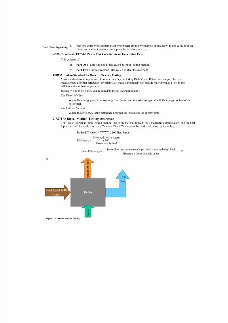
2.7.2 The Direct Method Testing Description
This is also known as 'input-output method' due to the fact that it needs only the useful output (steam) and the heat
input (i.e. fuel) for evaluating the efficiency. This efficiency can be evaluated using the formula :
Boiler Efficiency =Heat output
x 100 Heat input
. Heat addition to steamEfficiency = x 100
Gross heat in fuel
Boiler Efficiency = x 100 Steam flow rate x (steam enthalpy - feed water enthalpy) Fuel
firing rate x Gross calorific value
Figure 2.25 : Direct Method Testing
50
7/27/2019 Thermal Power plant Unit-2-58.docx
http://slidepdf.com/reader/full/thermal-power-plant-unit-2-58docx 33/65
Measurements Required for Direct Method Testing Steam Power Plant
Heat Input
Both heat input and heat output must be measured. The measurement of heat input requires knowledge of
the calorific value of the fuel and its flow rate in terms of mass or volume, according to the nature of thefuel.
For Gaseous Fuel
A gas meter of the approved type can be used and the measured volume should be corrected for
temperature and pressure. A sample of gas can be collected for calorific value determination, but it is
usually acceptable to use the calorific value declared by the gas suppliers.
For Liquid Fuel
The meter, which is usually installed on the combustion appliance, should be regarded as a rough
indicator only and, for test purposes, a meter calibrated for the particular oil is to be used and over a
realistic range of temperature should be installed. Even better is the use of an accurately calibrated
day tank.
For Solid Fuel
The accurate measurement of the flow of coal or other solid fuel is very difficult. The measurement
must be based on mass, which means that bulky apparatus must be set up on the boiler-house floor.Samples must be taken and bagged throughout the test, the bags sealed and sent to a laboratory for
analysis and calorific value determination. In some more recent boiler houses, the problem has been
alleviated by mounting the hoppers over the boilers on calibrated load cells, but these are yet
uncommon.
Heat Output
There are several methods, which can be used for measuring heat output. With steam boilers, an installed
steam meter can be used to measure flow rate, but this must be corrected for temperature and pressure. In
earlier years, this approach was not favoured due to the change in accuracy of orifice or venturi meters with
flow rate. It is now more viable with modern flow meters of the variable-orifice or vortex-shedding types.
The alternative with small boilers is to measure feed water, and this can be done by previously calibrating
the feed tank and noting down the levels of water during the beginning and end of the trial. Care should be
taken not to pump water during this period. Heat addition for conversion of feed water at inlet temperature
to steam, is considered for heat output.
In case of boilers with intermittent blowdown, blowdown should be avoided during the trial period. In caseof boilers with continuous blowdown, the heat loss due to blowdown should be calculated and added to the
heat in steam.
Merits and Demerits of Direct Method
Merits
(a) Plant people can evaluate quickly the efficiency of boilers.
(b) Requires few parameters for computation.
(c) Needs few instruments for monitoring.

7/27/2019 Thermal Power plant Unit-2-58.docx
http://slidepdf.com/reader/full/thermal-power-plant-unit-2-58docx 34/65
Power Plant Engineering (a) Does not give clues to the operator as to why efficiency of system is lower.
(b) Does not calculate various losses accountable for various efficiency levels.
(c) Evaporation ratio and efficiency may mislead, if the steam is highly wet due to water carryover
2.7.3 The Indirect Method Testing Description
The efficiency can be measured easily by measuring all the losses occurring in the boilers using the principles to
be described. The disadvantages of the direct method can be overcome by this method, which calculates the
various heat losses associated with boiler. The efficiency can be arrived at, by subtracting the heat loss fractions
from 100. An important advantage of this method is that the errors in measurement do not make significant change
in efficiency.
Thus if boiler efficiency is 90%, an error of 1% in direct method will result in significant change in efficiency, i.e.
90 ± 0.9 = 89.1 to 90.9. In indirect method, 1% error in measurement of losses will result in
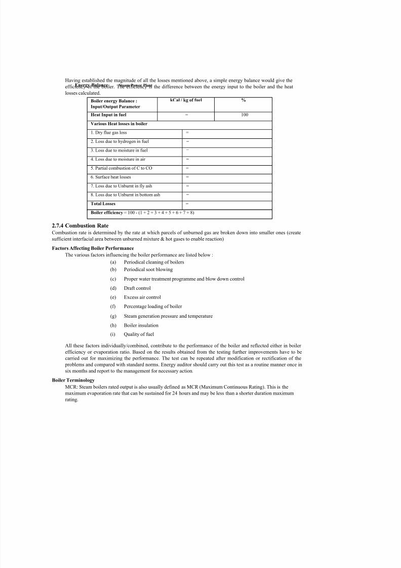
Efficiency = 100 - (10 ± 0.1) = 90 ± 0.1 = 89.9 to 90.1 The various heat losses occurring in the boiler are
Efficiency = 100 - (1 + 2 + 3 + 4 + 5 + 6 + 7 + 8) (by indirect method)Slfpain Ontnnt
The following losses are applicable to liquid, gas and solid fired boiler :
L1 - Loss due to dry flue gas (sensible heat)
L2 - Loss due to hydrogen in fuel (H2)
L3 - Loss due to moisture in fuel (H2O)
L4 - Loss due to moisture in air (H2O)
L5 - Loss due to carbon monoxide (CO)
L6 - Loss due to surface radiation, convection and other unaccounted*.
*Losses which are insignificant and are difficult to measure.
The following losses are applicable to solid fuel fired boiler in addition to above : L7 - Unburnt losses in fly ash (Carbon)
L8 - Unburnt losses in bottom ash (Carbon)
Boiler Efficiency by indirect method = 100 - (L1 + L2 + L3 + L4 + L5 + L6 + L7 + L8)
Figure 2.26 : Indirect Method Testing
7/27/2019 Thermal Power plant Unit-2-58.docx
http://slidepdf.com/reader/full/thermal-power-plant-unit-2-58docx 35/65

7/27/2019 Thermal Power plant Unit-2-58.docx
http://slidepdf.com/reader/full/thermal-power-plant-unit-2-58docx 36/65
Power Plant Engineering Boiler Rating
54
Conventionally, boilers are specified by their capacity to hold water and the steam generation rate. Often, the
capacity to generate steam is specified in terms of equivalent evaporation (kg of steam/hour at 100oC).
The equivalent of the evaporation of 1 kg of water at 100o
C to steam at 100o
C. Efficiency
In the boiler industry there are four common definitions of efficiency :
Combustion Efficiency
Combustion efficiency is the effectiveness of the burner only and relates to its ability to completely burn the
fuel. The boiler has little bearing on combustion efficiency. A well-designed burner will operate with as little
as 15 to 20% excess air, while converting all combustibles in the fuel to useful energy.
Thermal Efficiency
Thermal efficiency is the effectiveness of the heat transfer in a boiler. It does not take into account boiler
radiation and convection losses.
Boiler Efficiency
The term boiler efficiency is often substituted for combustion or thermal efficiency. True boiler efficiency is
the measure of fuel to steam efficiency.
Fuel to Steam EfficiencyFuel to steam efficiency is calculated using either of the two methods as prescribed by the ASME
(American Society for Mechanical Engineers) power test code, PTC 4.1. The first method is input output
method. The second method is heat loss method.
2.8 STEAM TURBINES
A steam turbine is a mechanical device that extracts thermal energy from pressurized steam, and converts it into rotary
motion. It has almost completely replaced the reciprocating piston steam engine primarily because of its greater thermal
efficiency and higher power-to-weight ratio. Because the turbine generates rotary motion, it is particularly suited to be
used to drive an electrical generator - about 80% of all electricity generation in the world is by use of steam turbines. The
steam turbine is a form of heat engine that derives much of its improvement in thermodynamic efficiency through the use
of multiple stages in the expansion of the steam, which results in a closer approach to the ideal reversible process.
Types
Steam turbines are made in a variety of sizes ranging from small 0.75 kW units (rare) used as mechanical drives for pumps, compressors and other shaft driven equipment, to 1,500,000 kW turbines used to generate electricity. There
are several classifications for modern steam turbines.
2.8.1 Steam Turbine Classification
Steam Turbines have been classified by :
(a) Details of stage design as (i) impulse
(ii) reaction

7/27/2019 Thermal Power plant Unit-2-58.docx
http://slidepdf.com/reader/full/thermal-power-plant-unit-2-58docx 37/65
(b) Steam supply and exhaust conditions asSteam P
°wer Plant
(i) Condensing
(ii) Back Pressure (Non Condensing)
(iii) Mixed Pressure
(iv) Reheat
(v) Extraction type (Auto or Controlled)
Condensing turbines are most commonly found in electrical power plants.
These turbines exhaust steam in a partially condensed state, typically of a
quality near 90%, at a pressure well below atmospheric to a condenser.
Non-condensing or backpressure turbines are most widely used for process
steam applications. The exhaust pressure is controlled by a regulating valve
to suit the needs of the process steam pressure. These are commonly found at
refineries, district heating units, pulp and paper plants, and desalination
facilities where large amounts of low pressure process steam are available.
Reheat turbines are also used almost exclusively in electrical power plants.In a reheat turbine, steam flow exits from a high pressure section of the
turbine and is returned to the boiler where additional superheat is added.
The steam then goes back into an intermediate pressure section of the turbine
and continues its expansion.
Extracting type turbines are common in all applications. In an extracting type
turbine, steam is released from various stages of the turbine, and used for
industrial process needs or sent to boiler feedwater heaters to improve overall
cycle efficiency. Extraction flows may be controlled with a valve, or left
uncontrolled.
Induction turbines introduce low pressure steam at an intermediate stage to
produce additional power.
(c) Casing or shaft arrangement as
(i) Single Casing
(ii) Tandem compound
(iii) Cross Compound
Single casing units are the most basic style where a single casing and shaft
are coupled to a generator. Tandem compound are used where two or more
casings are directly coupled together to drive a single generator. A cross
compound turbine arrangement features two or more shafts not in line driving
two or more generators that often operate at different speeds. A cross
compound turbine is typically used for many large applications.
55Figure 2.27 : Impulse Main Propulsion Turbine

7/27/2019 Thermal Power plant Unit-2-58.docx
http://slidepdf.com/reader/full/thermal-power-plant-unit-2-58docx 38/65
Power Plant Engineering (d) Number of Exhaust Stages in Parallel
56
(e) Direction of steam flow
(f) Steam supply - Superheated or saturated.
2.8.2 Principle of Operation and Design
An ideal steam turbine is considered to be an isentropic process, or constant entropy process, in which the entropy
of the steam entering the turbine is equal to the entropy of the steam leaving the turbine. No steam turbine is truly
"isentropic", however, with typical isentropic efficiencies ranging from 20%-90% based on the application of the
turbine. The interior of a turbine comprises several sets of blades, or "buckets" as they are more commonly referred
to. One set of stationary blades is connected to the casing and one set of rotating blades is connected to the shaft.
The sets intermesh with certain minimum clearances, with the size and configuration of sets varying to efficiently
exploit the expansion of steam at each stage.
2.8.3 Turbine Efficiency
To maximize turbine efficiency the steam is expanded, generating work, in a number of stages. These stages are
characterized by how the energy is extracted from them and are known as either impulse or reaction turbines. Most
steam turbines use a mixture of the reaction and impulse designs : each stage behaves as either one or the other, but
the overall turbine uses both. Typically, higher pressure sections are impulse type and lower pressure stages are
reaction type.
2.8.4 Impulse Turbines
An impulse turbine has fixed nozzles that orient the steam flow into high speed jets. These jets contain significant
kinetic energy, which the rotor blades, shaped like buckets, convert into shaft rotation as the steam jet changesdirection. A pressure drop occurs across only the stationary blades, with a net increase in steam velocity across the
stage.
Figure 2.28 : Schematic Diagram Outlining the difference between an
Impulse and a Reaction Turbine
7/27/2019 Thermal Power plant Unit-2-58.docx
http://slidepdf.com/reader/full/thermal-power-plant-unit-2-58docx 39/65
57
As the steam flows through the nozzle its pressure falls from inlet pressure to the exitSteam Power Plant
pressure (atmospheric pressure, or more usually, the condenser vacuum). Due to this
higher ratio of expansion of steam in the nozzle the steam leaves the nozzle with a very
high velocity. The steam leaving the moving blades is a large portion of the maximum
velocity of the steam when leaving the nozzle. The loss of energy due to this higher exit
velocity is commonly called the "carry over velocity" or "leaving loss".
2.8.5 Reaction Turbines
In the reaction turbine, the rotor blades themselves are arranged to form convergent nozzles. This type of turbine makes
use of the reaction force produced as the steam accelerates through the nozzles formed by the rotor. Steam is directed onto
the rotor by the fixed vanes of the stator. It leaves the stator as a jet that fills the entire circumference of the rotor. The
steam then changes direction and increases its speed relative to the speed of the blades. A pressure drop occurs across both
the stator and the rotor, with steam accelerating through the stator and decelerating through the rotor, with no net change in
steam velocity across the stage but with a decrease in both pressure and temperature, reflecting the work performed in the
driving of the rotor.
2.8.6 Steam Turbine Start up
When warming up a steam turbine for use, the main steam stop valves (after the boiler)
have a bypass line to allow superheated steam to slowly bypass the valve and proceed to heat up the lines in the system
along with the steam turbine. Also a turning gear is engaged when there is no steam to the turbine to slowly rotate the
turbine to ensure even heating to prevent uneven expansion. After first rotating the turbine by the turning gear,
allowing time for the rotor to assume a straight plane (no bowing), then the turning gear is disengaged and steam is
admitted to the turbine, first to the astern blades then to the ahead blades slowly rotating the turbine at 10 to 15 RPM to
slowly warm the turbine.
2.8.7 Precautions during Running
Problems with turbines are now rare and maintenance requirements are relatively small.
Any imbalance of the rotor can lead to vibration, which in extreme cases can lead to a blade letting go and punching
straight through the casing. It is, however, essential that the turbine be turned with dry steam. If water gets into the steam
and is blasted onto the blades (moisture carryover) rapid impingement and erosion of the blades can occur,
possibly leading to imbalance and catastrophic failure. Also, water entering the blades will likely result in the destruction
of the thrust bearing for the turbine shaft. To prevent this, along with controls and baffles in the boilers to ensure high
quality steam,
condensate drains are installed in the steam piping leading to the turbine.
2.8.8 Speed Regulation
The control of a turbine with a governor is essential, as turbines need to be run up slowly, to prevent damage while some
applications (such as the generation of alternating current electricity) require precise speed control. Uncontrolled
acceleration of the turbine rotor can lead to an overspeed trip, which causes the nozzle valves that control the flow of
steam to the turbine to close. If this fails then the turbine may continue accelerating until it breaks apart, often
spectacularly. Turbines are expensive to make,
requiring precision manufacture and special quality materials. During normal operation in
synchronization with the electricity net power plants are governed with a five percent speed
droop. This means the full load speed is 100% and the no load speed is 105%.
This is required for the stable operation of the net without hunting and dropouts of power plants. Normally the changes in
speed are minor. Adjustments in power output are made by slowly raising the droop curve by increasing the spring
pressure on a centrifugal governor. Generally this is a basic system requirement for all power plants because the older and
newer plants have to be compatible in response to the instantaneous changes in frequency without depending on outside
communication.

7/27/2019 Thermal Power plant Unit-2-58.docx
http://slidepdf.com/reader/full/thermal-power-plant-unit-2-58docx 40/65
Power Plant Eng
ineering 2.8.9 The Governor
The speed of the machine is controlled by the automatic opening and closing of the admission
valves under the control of a governor, of the spring-weighted type (Figure 2.29) attacheddirectly to the top end of the turbine shaft. The action of the governor depends on the balance
of force exerted by the spring, and the centrifugal effort of the rectangular-shaped weights at
the lower end; the moving weights acting through the knife-edge suspension tend to pull down
the lever against the resistance of the heavy helical spring. The governor is provided with an
auxiliary spring on the outside of the governor dome for varying the speed while
synchronizing. The tension of the auxiliary spring is regulated by a small motor wired to the
switchboard. This spring should be used only to correct slight changes in speed. Any marked
change should be corrected by the use of the large hexagonal nut in the upper plate of the
governor frame. This nut is screwed down to increase the speed, and upward to decrease it.
Elements of Turbines and their Functions
Other than the operating and controlling equipment, similarity exists in both the impulse
and reaction turbines. These include foundations, casings, nozzles, rotors, bearings, and
shaft glands.
Foundations
Turbine foundations are built up from a structural foundation in the hull to provide a
rigid supporting base. All turbines are subjected to varying degrees of temperature-from
that existing during a secured condition to that existing during full-power operation.
Therefore, means are provided to allow for expansion and contraction.
At the forward end of the turbine, there are various ways to give freedom of movement.Elongated bolt holes or grooved sliding seats are used so that the forward end of the
turbine can move fore and aft as either expansion or contraction takes place. The
forward end of the turbine may also be mounted with a flexible I-beam that will flex
either fore or aft.
Figure 2.29 : The Governor
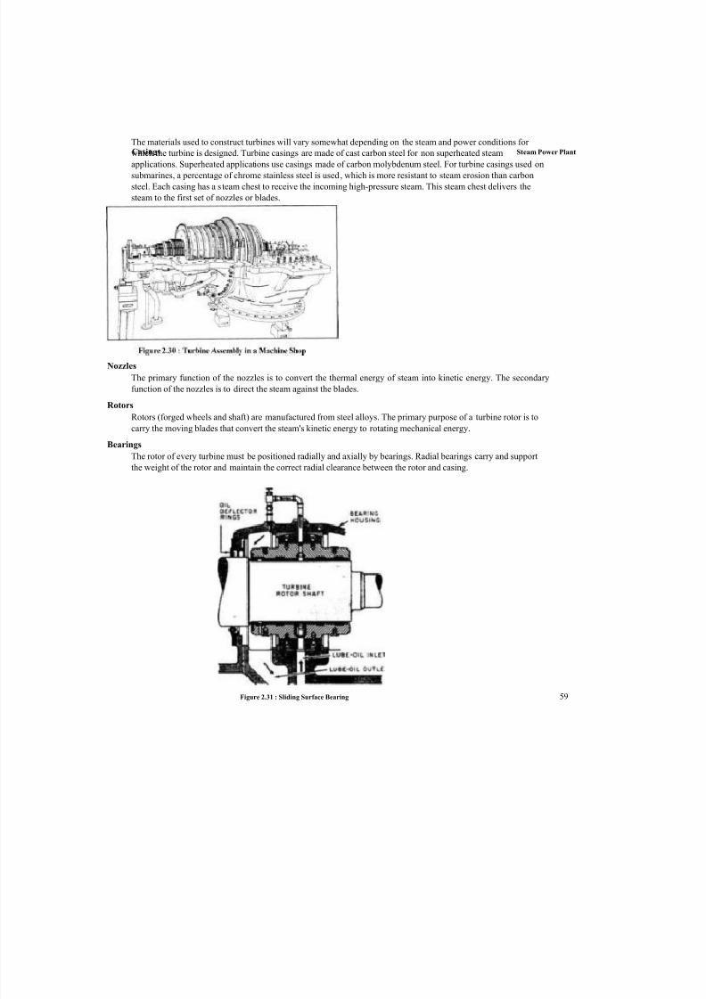
7/27/2019 Thermal Power plant Unit-2-58.docx
http://slidepdf.com/reader/full/thermal-power-plant-unit-2-58docx 41/65
Casings Steam Power Plant The materials used to construct turbines will vary somewhat depending on the steam and power conditions for
which the turbine is designed. Turbine casings are made of cast carbon steel for non superheated steam
applications. Superheated applications use casings made of carbon molybdenum steel. For turbine casings used on
submarines, a percentage of chrome stainless steel is used, which is more resistant to steam erosion than carbon
steel. Each casing has a steam chest to receive the incoming high-pressure steam. This steam chest delivers the
steam to the first set of nozzles or blades.
Nozzles
The primary function of the nozzles is to convert the thermal energy of steam into kinetic energy. The secondary
function of the nozzles is to direct the steam against the blades.
Rotors
Rotors (forged wheels and shaft) are manufactured from steel alloys. The primary purpose of a turbine rotor is to
carry the moving blades that convert the steam's kinetic energy to rotating mechanical energy.
Bearings
The rotor of every turbine must be positioned radially and axially by bearings. Radial bearings carry and support
the weight of the rotor and maintain the correct radial clearance between the rotor and casing.
Figure 2.31 : Sliding Surface Bearing 59

7/27/2019 Thermal Power plant Unit-2-58.docx
http://slidepdf.com/reader/full/thermal-power-plant-unit-2-58docx 42/65
Power Plant Engineering Axial (thrust) bearings limit the fore-and-aft travel of the rotor. Thrust bearings
take care of any axial thrust, which may develop on a turbine rotor and hold the
turbine rotor within definite axial positions.
All main turbines and most auxiliary units have a bearing at each end of the rotor.
Bearings are generally classified as sliding surface (sleeve and thrust) or as rolling
contact (antifriction ball or roller bearings). Figure shows a typical sliding surface
bearing.
Shaft Packing Glands
Shaft packing glands prevent the leaking of steam out of or air into the turbine casing
where the turbine rotor shaft extends through the turbine casing. Labyrinth and carbon
rings are two types of packing. They are used either separately or in combination.
Labyrinth packing consists of rows of metallic strips or fins. The strips fasten to the
gland liner so there is a small space between the strips and the shaft. As the steam
from the turbine casing leaks through the small space between the packing strips and
the shaft, steam pressure gradually reduces.
60
INNER IABTRINTM
RINCS(PACK!NO I
LABYRINTH RINGStPACKING)
O 1 Nt ROIOH S « A f T SCALING
STfAMSUPPLY
Figure 2.32 : Labyrinth Packing Gland
GAR T E R
S P R I N G
C A R BON
R I N G S
G L A NDL E A K O F F Figure 2.33 : Carbon Packing Gland
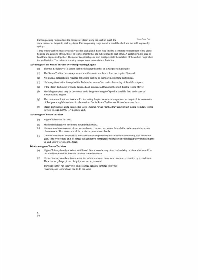
7/27/2019 Thermal Power plant Unit-2-58.docx
http://slidepdf.com/reader/full/thermal-power-plant-unit-2-58docx 43/65
7/27/2019 Thermal Power plant Unit-2-58.docx
http://slidepdf.com/reader/full/thermal-power-plant-unit-2-58docx 44/65
Power Plant En
gin
eerin
g2.8.10 Performance Analysis of Steam Turbines
Need for Performance Analysis
(a) To increase availability and reliability.
(b) To reduce operating cost and maximize production.
(c) To assess the effect of blade washes.
(d) To identify optimum range of throttle loading rates.
(e) To maintain power demand to the plant or grid.
(f) To avoid catastrophic shutdowns.
(g) To reduce maintenance expenditure.
(h) To determine the underlying causes of operating deviations
Parameters to be Monitored in Performance Analysis
Isentropic Efficiency
Used to determine machine performance trends and effects of maintenance
activities.
Power Characteristics
The power generation, actual or implied, together with expected generation at
design or clean conditions.
Efficiency/Power Deviation
Load independent comparison relative to design.
Pressure Ratios
Used together with the efficiency curves to determine optimum stage
performance selection.
Steam Velocities
Used as an indicator of the amount of energy removed from the steam
feedstock, from each stage.Steam Rates
Illustrates changes in performance deviation, relative to isentropic
expansion.
Power Vs Steam
Scatter plot identifies turbine degradation and optimum control regions.
Operating Loss Cost
Tracks current and historical 'lost opportunity' - both instantaneous and
cumulative.
Thermal Efficiency
The overall thermal efficiency of a steam turbine plant can be represented by the
ratio of the net mechanical energy available to the energy within the fuel
supplied.
. Net outflow of shaft work Energy rejectedT hermal Efficiency = -------------------------------------- = 1 --------------------------
Calorific value of fuel Energy sup plied
Mechanical Efficiency
Mechanical Efficiency of a turbine is the ratio of the brake output to the 62
internal input. The Mechanical efficiency is an index of the external losses.

7/27/2019 Thermal Power plant Unit-2-58.docx
http://slidepdf.com/reader/full/thermal-power-plant-unit-2-58docx 45/65
Casings Steam Power Plant
Heat Rate Units and Definitions
The economy or efficiency of a steam power plant cycle is expressed in terms of heat rate, which is
total thermal input to the cycle divided by the electrical output of the units.Actual Steam Rate
The actual steam rate of a turbine can be determined by dividing the actual throttle steam flow rate
by the actual corresponding kilowatts, at the generator terminals, produced by that amount of steam.
The actual steam rate can also be determined by dividing the theoretical steam rate by the engine
efficiency of the turbine generator.
2.9 CONDENSER
2.9.1 Functions of Condensers
The main purposes of the condenser are to condense the exhaust steam from the turbine for reuse in the cycle and to
maximize turbine efficiency by maintaining proper vacuum. As the operating pressure of the condenser is lowered
(vacuum is increased), the enthalpy drop of the expanding steam in the turbine will also increase. This will increase the
amount of available work from the turbine (electrical output). By lowering the condenser operating pressure, the
following will occur :
(a) Increased turbine output
(b) Increased plant efficiency
(c) Reduced steam flow (for a given plant output)
It is therefore very advantageous to operate the condenser at the lowest possible pressure (highest vacuum).
2.9.2 Condenser Types
There are two primary types of condensers that can be used in a power plant :
(a) Direct Contact
(b) Surface
Direct contact condensers condense the turbine exhaust steam by mixing it directly with cooling water. The older type
Barometric and Jet-Type condensers operate on similar principles.
Steam surface condensers are the most commonly used condensers in modern power plants. The exhaust steam from the
turbine flows on the shell side (under vacuum) of the condenser, while the plant's circulating water flows in the tube side.
The source of the circulating water can be either a closed-loop (i.e. cooling tower, spray pond, etc.) or once through (i.e.
from a lake, ocean, or river). The condensed steam from the turbine, called condensate, is collected in the bottom of the
condenser, which is called a hotwell. The condensate is then pumped back to the steam generator to repeat the cycle.
2.9.3 Surface Condenser
The surface condenser is a shell and tube heat exchanger in which cooling water is circulated through the tubes. The
exhaust steam from the low pressure turbine enters the shell where it is cooled and converted to condensate (water) by
flowing over the tubes as shown in the diagram. Such condensers use steam ejectors or rotary motor-driven exhausters
for continuous removal of air and gases from the steam side to maintain vacuum.

7/27/2019 Thermal Power plant Unit-2-58.docx
http://slidepdf.com/reader/full/thermal-power-plant-unit-2-58docx 46/65
Water outlet Steam To ejector vacuum system Power Plant Engineering
64
L li ^ Flanges
ILt —
1
Baffle
__ L_ , Baffle ~ P _ r | j [
Of 1
t Baffle t.
Tubesheet t. Tubesheet
Condensate
t Flan
ged
cover
plate
Water inlet
hr
Exhaust Steam
r _3 Flange
*r: TubeSheet Flanges r — I
- Jr Carbon \ -----------------
Steel ̂1 — |
Flanges ^ Flanges |
□
Tube Flanges.. . Sheet
Vent v.
_L 1
Stainless Steel
Expansion Joints-----------------
Outlet
Water
Box
Inlet Water Box
/*■ n- Zinc Plate
Mounted On TubeSheet
Circulating
Outlet Water Circulating
Inlet Water Springs Springs
x x x xConcrete X
X X X
x x x xConcrete X
X X X
To
Condensate Pump
Figure 2.34 : Diagram of a Typical Water-cooled Surface Condenser
For best efficiency, the temperature in the condenser must be kept as low as practical in
order to achieve the lowest possible pressure in the condensing steam. Since the condenser
temperature can almost always be kept significantly below 100oC where the vapor pressure
of water is much less than atmospheric pressure, the condenser generally works under
vacuum. Thus leaks of non-condensable air into the closed loop must be prevented.The condenser generally uses either circulating cooling water from a cooling tower to
reject waste heat to the atmosphere, or once-through water from a river, lake or ocean.
Hotwell
Condensat
e
Note : Tubes are brass, cupro nickel, titanium or stainless steel. The tubes are expanded or rolled and bell
mouthed at the ends in the tube sheets.
Figure 2.35 : Typical Power Plant Condenser
The diagram depicts a typical water-cooled surface condenser as used in power stations to
condense the exhaust steam from a steam turbine driving an electrical generator as well in
other applications
2.9.4 Condenser Components and their Functions Shell
The shell is the condenser's outermost body and contains the heat exchanger tubes.
The shell is fabricated from carbon steel plates and is stiffened as needed to provide
rigidity for the shell. When required by the selected design, intermediate plates are
installed to serve as baffle plates that provide the desired flow path of the condensing
steam. The plates also provide support that help prevent sagging of long tube lengths.
For most water-cooled surface condensers, the shell is under vacuum during
normal operating conditions.
Drain □ □ Drain

7/27/2019 Thermal Power plant Unit-2-58.docx
http://slidepdf.com/reader/full/thermal-power-plant-unit-2-58docx 47/65
Hotwell Steam Power Plant
65
At the bottom of the shell, where the condensate collects, an outlet is installed. In some
designs, a sump (often referred to as the hotwell) is provided. Condensate is pumped from
the outlet or the hotwell for reuse as boiler feedwater.
Vacuum System
For a steam ejector, the motive fluid is steam.
For water-cooled surface condensers, the shell's internal vacuum is most commonly
supplied by and maintained by an external steam jet ejector system. Such an ejector
system uses steam as the motive fluid to remove any non- condensable gases that
may be present in the surface condenser. The Venturi effect, which is a particular
case of Bernoulli's principle, applies to the operation of steam jet ejectors.
Motor driven mechanical vacuum pumps, such as the liquid ring type, are also
popular for this service.
Motive fluid
Tube Sheets
At each end of the shell, a sheet of sufficient thickness usually made of stainlesssteel is provided, with holes for the tubes to be inserted and rolled. The inlet end of
each tube is also bell mouthed for streamlined entry of water. This is to avoid eddies
at the inlet of each tube giving rise to erosion, and to reduce flow friction. Some
makers also recommend plastic inserts at the entry of tubes to avoid eddies eroding
the inlet end. In smaller units some manufacturers use ferrules to seal the tube ends
instead of rolling. To take care of length wise expansion of tubes some designs have
expansion joint between the shell and the tube sheet allowing the latter to move
longitudinally. In smaller units some sag is given to the tubes to take care of tube
expansion with both end water boxes fixed rigidly to the shell.
Tubes
Generally the tubes are made of stainless steel, copper alloys such as brass or bronze,
cupro nickel, or titanium depending on several selection criteria. The use of copper
bearing alloys such as brass or cupro nickel is rare in new plants, due to
environmental concerns of toxic copper alloys. Also depending on the steam cycle
water treatment for the boiler, it may be desirable to avoid tube materials containing
copper. Titanium condenser tubes are usually the best technical choice; however the
use of titanium condenser tubes has been virtually eliminated by the sharp increases in
the costs for this material. The tube lengths range to about 17 m for modern power
plants, depending on the size of the condenser. The size chosen is based on
transportability from the manufacturers' site and ease of erection at the installation
site.
Motivefluid
nozzle
Converging Diverging outlet
diffuser
Diffuser throat
Inlet gas, liquid, or other
Figure 2.36 : Diagram of a Typical Modern Injector or Ejector
Outlet

7/27/2019 Thermal Power plant Unit-2-58.docx
http://slidepdf.com/reader/full/thermal-power-plant-unit-2-58docx 48/65
Power Plant Engineering Waterboxes
66
The tube sheet at each end with tube ends rolled, for each end of the condenser is
closed by a fabricated box cover known as a waterbox, with flanged connection to thetube sheet or condenser shell. The waterbox is usually provided with man holes on
hinged covers to allow inspection and cleaning.
These waterboxes on inlet side will also have flanged connections for cooling water
inlet butterfly valves, small vent pipe with hand valve for air venting at higher level,
and hand operated drain valve at bottom to drain the waterbox for maintenance.
Similarly on the outlet waterbox the cooling water connection will have large flanges,
butterfly valves, vent connection also at higher level and drain connections at lower
level. Similarly thermometer pockets are located at inlet and outlet pipes for local
measurements of cooling water temperature.
2.9.5 Condensate Pumps
Condensate pumps are those kinds of pumps that are used to collect and transport condensate
back into a steam system for reheating and reuse, or to remove unwanted condensate.
Condensate pumps have a tank in which condensate can accumulate. The tank size varies
depending on the application. The accumulating liquid raises a float switch which energizesthe pump. The pump then runs until the level of liquid in the tank is substantially lowered.
Some pumps contain a two-stage switch. As the liquid rises to the trigger point of the first
stage, the pump starts working. If the liquid continues to rise, the second stage will be
triggered. This stage may switch off the HVAC equipment, which is, preventing the
production of further condensate, trigger an alarm or both.
Types of Condensate Pump
Boiler Feed Pump
This pump closes the boiler, steam and condensate loop by returning the
condensate back into the system for reuse.
Sump Pump
This pump is installed in compartments to remove the unwanted build-up of
water.
In a steam power plant, the condensate pump is normally located adjacent to the main
condenser hotwell often directly below it. This pump sends the water to a make-up tank closer to the steam generator or boiler. If the tank is also designed to remove dissolved oxygen from
the condensate, it is known as a De aerating feed tank (DFT). The output of the DFT supplies
the feed booster pump which, in turn, supplies the feed pump (feedwater pump) which returns
the feedwater to the boiler so the cycle can start over. Two pumps in succession are used to
provide sufficient Net Positive Suction Head to prevent cavitation and the subsequent damage
associated with it.
Circulating Pumps
Condenser circulating pumps are used to pump cooing water through the condenser.
The source of the cooling water can be the sea, lake, river or a cooling tower. Low
speed -horizontal-double suction-volute centrifugal pumps are used for this application.
This pump has a simple but rugged design that allows ready access to interior for
examination and rapid dismantling if repairs are required.
Atmospheric Relief Valves
Atmospheric relief valves provide automatic protection of costly condenser equipment.These valves are as important as trip throttle valves, over speed governors, and other
devices for power plant protection. Atmospheric relief valves are designed and
manufactured with the finest materials and the highest quality workmanship.
7/27/2019 Thermal Power plant Unit-2-58.docx
http://slidepdf.com/reader/full/thermal-power-plant-unit-2-58docx 49/65
67
Atmospheric relief valves open and close automatically. Each valve needs to beSteam P
°wer Plant
installed vertically and properly leveled for smooth operation. Special ring seals
and a water seal is provided for zero leakage in full vacuum conditions. Each
valve opens immediately when pressure increases slightly above atmospheric
pressure. Higher than atmospheric set pressures can be provided with internally
spring loaded discs. During regular maintenance and as many times as possible,
each atmospheric valve should be opened by turning the hand wheel clockwise
then closing the valves by turning counter clockwise. This process ensures non-
binding and self-cleaning valve action.
Requirements of a Good Condensing System
The requirements of ideal surface condenser used for power plants are as follows :
(a) The steam entering the condenser should be evenly distributed over
the whole cooling surface of the condenser vessel with minimum
pressure loss.
(b) The amount of cooling water being circulated in the condenser should
be so regulated that the temperature of cooling water leaving the
condenser is equivalent to saturation temperature of steamcorresponding to steam pressure in the condenser. This will help in
preventing under cooling of condensate.
(c) The deposition of dirt on the outer surface of tubes should be prevented.
Passing the cooling water through the tubes and allowing the steam to
flow over the tubes achieve this.
(d) There should be no air leakage into the condenser because presence of
air destroys the vacuum in the condenser and thus reduces the work
obtained per kg of steam. If there is leakage of air into the condenser air
extraction pump should be used to remove air as rapidly as possible.
2.10 COOLING TOWER
Functions
Cooling Towers have one function :
• Remove heat from the water discharged from the condenser so that the water can
be discharged to the river or recirculated and reused.
2.10.1 What is a Cooling Tower
A cooling tower extracts heat from water by evaporation. In an evaporative cooling
tower, a small portion of the water being cooled is allowed to evaporate into a moving air
stream to provide significant cooling to the rest of that water stream.
Cooling Towers are commonly used to provide lower than ambient water temperatures and
are more cost effective and energy efficient than most other alternatives. The smallest
cooling towers are structured for only a few litres of water per minute while the largest
cooling towers may handle upwards of thousands of litres per minute. The pipes are
obviously much larger to accommodate this much water in the larger towers and can range
up to 12 inches in diameter.
2.10.2 How Cooling Towers Work When water is reused in the process, it is pumped to the top of the cooling tower and will
then flow down through plastic or wood shells, much like a honeycomb found in a bee's
nest. The water will emit heat as it is downward flowing which mixes with the above air
flow, which in turn cools the water. Part of this water will also evaporate, causing it to lose
even more heat.

7/27/2019 Thermal Power plant Unit-2-58.docx
http://slidepdf.com/reader/full/thermal-power-plant-unit-2-58docx 50/65
Power Plant Eng
in
eering 2.10.3 Types of Cooling Towers
One way to distinguish between cooling towers is how the air and water interact, open
cooling towers or closed cooling towers. Open cooling towers, also called direct cooling
towers, allow the water to come into contact with outside air. If cooled water is returned from
the cooling tower to be used again, some water must be added to replace the water that has
been lost. Pollutants are able to enter into the water used in these processes and must be
filtered out. Another method of combating the excess minerals and pollutants is some means
of a dissolved solid control, such as a blow down. With this, a small percentage of the flow is
drained off to aid in the removal of these contaminants. This is fairly effective, but not as
efficient as filtration.
Closed loop (or closed circuit) cooling tower systems, also called indirect cooling tower
systems, do not allow the water to come into contact with any outside substance, therefore
keeping the water more pure due to the lack of foreign particles introduced.
Another classification of cooling towers is made between field assembled towers and factory
assembled towers. Field assembled towers are shipped in pieces and assembled on site by a
highly qualified and certified installation team. Factory assembled towers typically only
require the fan motor to be mounted.
2.10.4 Natural Draft Towers Natural draft towers are typically about 120 m high, depending on the differential pressure
between the cold outside air and the hot humid air on the inside of the tower as the driving
force. No fans are used.
Whether the natural or mechanical draft towers are used depends on climatic and
operating requirement conditions.
The green flow paths show how the warm water leaves the plant proper, is pumped to the
natural draft cooling tower and is distributed. The cooled water, including makeup from the
lake to account for evaporation losses to the atmosphere, is returned to the condenser.
Mechanical Draft
Mechanical draft towers uses fans (one or more) to move large quantities of air through
the tower. They are two different classes :
(a) Forced draft cooling towers
(b) Induced draft cooling towers
The air flow in either class may be cross flow or counter flow with respect to thefalling water. Cross flow indicates that the airflow is horizontal in the filled portion of
the tower while counter flow means the air flow is in the opposite direction of the
falling water.
The counter flow tower occupies less floor space than a cross flow tower but is taller
for a given capacity. The principle advantages of the cross flow tower are the low
pressure drop in relation to its capacity and lower fan power requirement leading to
lower energy costs.
All mechanical towers must be located so that the discharge air diffuses freely without
recirculation through the tower, and so that air intakes are not restricted. Cooling
towers should be located as near as possible to the refrigeration systems they serve, but
should never be located below them so as to allow the condenser water to drain out of
the system through the tower basin when the system is shut down.
Forced Draft
The forced draft tower, has the fan, basin, and piping located within the
tower structure. In this model, the fan is located at the base. There are no louvered exterior walls. Instead, the
structural steel or wood framing is covered with paneling made of aluminum, galvanized steel, or asbestos /to
cement boards.

7/27/2019 Thermal Power plant Unit-2-58.docx
http://slidepdf.com/reader/full/thermal-power-plant-unit-2-58docx 51/65
Steam Power Plant
During operation, the fan forces air at a low velocity horizontally through the
packing and then vertically against the downward flow of the water that occurs
on either side of the fan. The drift eliminators located at the top of the tower
remove water entrained in the air. Vibration and noise are minimal since the
rotating equipment is built on a solid foundation. The fans handle mostly dry
air, greatly reducing erosion and water condensation problems.
Induced Draft
The induced draft tower show in the following picture has one or more fans,
located at the top of the tower, that draw air upwards against the downward
flow of water passing around the wooden decking or packing. Since the airflow
is counter to the water flow, the coolest water at the bottom is in contact with
the driest air while the warmest water at the top is in contact with the moist air,
resulting in increased heat transfer efficiency.
Air
Otflet
Air _ A
Water
„ Waltr
Outlet
Figure 2.38 : Induced Draft
Figure 2.37 : Mechanical Draft
Fan
Water
Aif _
Inlet
Otflet
Air
Air
Met
69

7/27/2019 Thermal Power plant Unit-2-58.docx
http://slidepdf.com/reader/full/thermal-power-plant-unit-2-58docx 52/65
Power Plant Engineering Hybrid Draft They are equipped with mechanical draft fans to augment airflow. Consequently,
they are also referred to as fan-assisted natural draft towers. The intent of their design is to minimize the power required for the air movement, but to do so with the
least possible stack cost impact. Properly designed fans may need to be operated
only during periods of high ambient and peak loads.Air out
2.11 STEAM POWER STATION CONTROL
2.11.1 Basic Components of a Control System
Most control functions are implemented by means of a computer-based system, so we
shall now briefly look at a typical configuration known as DCS.
DCS stands for 'distributed control system'. The term 'distributed' means that several
processors are operating together. This is usually achieved by dedicating tasks to different
machines. It does not necessarily mean that the separate computers are physically located
in different areas of the plant.
Figure 2.40 : The Central System Cabinets
Figure 2.39 : Hybrid Draft
Figure 2.40 shows how a typical system may be arranged. The following notes relate to
individual parts of that system.
AlirmJeve
m printer
Operator workstation 1 Operator workstation 2 Enjineetrg/diagnostics
workstation and primer
Signals to actuators. Signals Iran motor starters
etc. transmitters, Unit switches etc.
70

7/27/2019 Thermal Power plant Unit-2-58.docx
http://slidepdf.com/reader/full/thermal-power-plant-unit-2-58docx 53/65
Located near the centre are the cabinets which house the processors that execute theSteam Power Plant
control functions. These cubicles also contain the attendant interface and input/output
(I/O) cards and the necessary power supply units (PSUs). The latter will usually be
duplicated or triplicated, with automatic changeover from one to another in the event of
the first failing. This automatic changeover is often referred to as 'diode auctioneering'
because silicon diodes are used to feed power from each unit onto a common bus-main.
In the event of the operational power-supply unit failing, its diode prevents a power
reversal while the back-up power unit takes over. At this time it is important that the
system should raise an alarm to warn that a PSU failure has occurred. Otherwise the
DCS will continue to operate with a diminished power-supply reserve and any further
failure could have serious consequences.
The I/O cards consist of analogue and digital input and output channels. Analogue inputs convert the incoming signals to
a form which can be read by the system. The printed-circuit cards for analogue inputs may or may not provide 'galvanic
isolation'.
With a galvanically isolated device the signal circuit is electrically isolated from others,
from the system earth and from the power-supply common rail.
Termination and Marshalling
It is important to understand that the grouping of inputs and outputs on the I/Ocards does not always correspond with the grouping of signals into multipair
cables, which is dictated by the physical arrangement of equipment on the plant.
While it is sensible to avoid mixing different control systems (e.g. feed water
control and combustion control) onto a single card, the signals associated with a
single system will not necessarily all be carried in the same cable. The result is that
a certain degree of cross connection or 'marshalling' is always required.
Operator Workstations
The operator workstations consist of screens on which plant information can be
observed, plus keyboards, trackballs or 'mouse' devices allowing the operator to
send commands to the system. They also comprise printers for operational records,
logging of events (such as start-up of a pump), or alarms. Some systems also
provide plotters
2.11.2 Compressed Air Control Systems
Compressed air system controls match the compressed air supply with system demand (although not always in real-time)
and are one of the most important determinants of overall system energy efficiency. Proper control is essential to efficientsystem operation and high performance. The objective of any control strategy is also to shut off unneeded compressors or
delay bringing on additional compressors until needed. All units which are on should be run at full-load, except for one
unit for trimming.
Individual Compressor Control Strategies
Controls such as start/stop and load/unload respond to reductions in air demand,
increasing compressor discharge pressure by turning the compressor off or unloading
it so that it does not deliver air for periods of time. Modulating inlet and multi-step
controls allow the compressor to operate at part load and deliver a reduced amount of
air during periods of reduced demand.
Start/Stop
Start/stop is the simplest control available and can be applied to either reciprocating or
rotary screw compressors. The motor driving the compressor is turned on or off in
response to the discharge pressure of the machine. Typically, a simple pressure switch
provides the motor start/stop signal.
Load/Unload
Load/unload control, also known as constant speed control, allows the motor to
run continuously, but unloads the compressor when the discharge pressure is
inadequate, but in most cases, an unloaded compressor will consume 15-35% of
full load power while delivering no useful work. 71

7/27/2019 Thermal Power plant Unit-2-58.docx
http://slidepdf.com/reader/full/thermal-power-plant-unit-2-58docx 54/65
Power Plant Engineering Modulating Controls Modulating inlet control allows the output of a compressor to be varied to meet flow requirements. Throttling is
usually accomplished by closing down the inlet valve, thereby restricting inlet air to the compressor. With the
use of inlet guide vanes which direct the air in the same direction as the impeller inlet, centrifugal compressors
yield more efficient results.
Multi-Step Controls
Some compressors are designed to operate in two or more partially loaded conditions. With such a control schemes,
output pressure can be closely controlled without requiring the compressor to start/stop or load/unload.
2.11.3 Controls and Instruments in a Modern Central Station Control Room
General Instrumentation and Control Design
Redundant systems and equipment shall be used in the instrumentation and control systems. Automated control data
processing/display shall be considered in order to enhance operability. The logic system shall contain redundant
central control units: one active and the second one in a hot standby mode.
An automatic shutdown override capability shall be designed into the control system to permit the operator to
bypass controls that normally initiate automatic shutdown. Control systems and instruments may be pneumatic, ac
or dc electrical, electronic digital, combination pneumatic and electronic, or hydraulic. Mechanical-hydraulic and
electro-hydraulic systems shall be used in conjunction with governor speed control systems. Pneumatic controls
shall not be used on power systems.
Supervisory Control and Data Acquisition System
The control system shall consist of a Programmable Logic Controller (PLC) based Supervisory Control and Data
Acquisition (SCADA) system. Input/output (I/O) modules located in Remote Terminal Units (RTUs) shall provide
the interface between the central control unit and other system hardware such as circuit breaker position indication
and control, generator paralleling switchgear, automatic transfer switches, UPS units, etc. Man-machine interface
(MMI) software shall run on a Windows based PC and interface with the central control unit.
Power Loss and Restoration
When the facility is operating solely on commercial power, loss of commercial power shall cause automatic
disconnect of all loads from the utility bus and initiation of the sequence to bring generator sets up to their full
capabilities. Then loads shall be incrementally added to the power plant bus. The sequence and restoration priority
for feeders serving technical loads, as well as consideration of the maximum time to restore the service, shall be
determined by the using an agency.
The central plant operator shall have an option for manually initiating the start sequence, bringing additional
generators on-line, or reconnecting the power plant bus to commercial power and returning the generator sets to the
condition existing prior to the loss of commercial power. Manual startup and shutdown control shall be provided
locally in each generator area for use by an operator-maintainer. Visual and audible alarms shall indicate out-of-
tolerance conditions, and critical information shall be printed out or otherwise recorded.
This requirement includes minor discrepancies which, if left uncorrected or allowed to degrade further, could result
in shutdown of the power-generating unit.
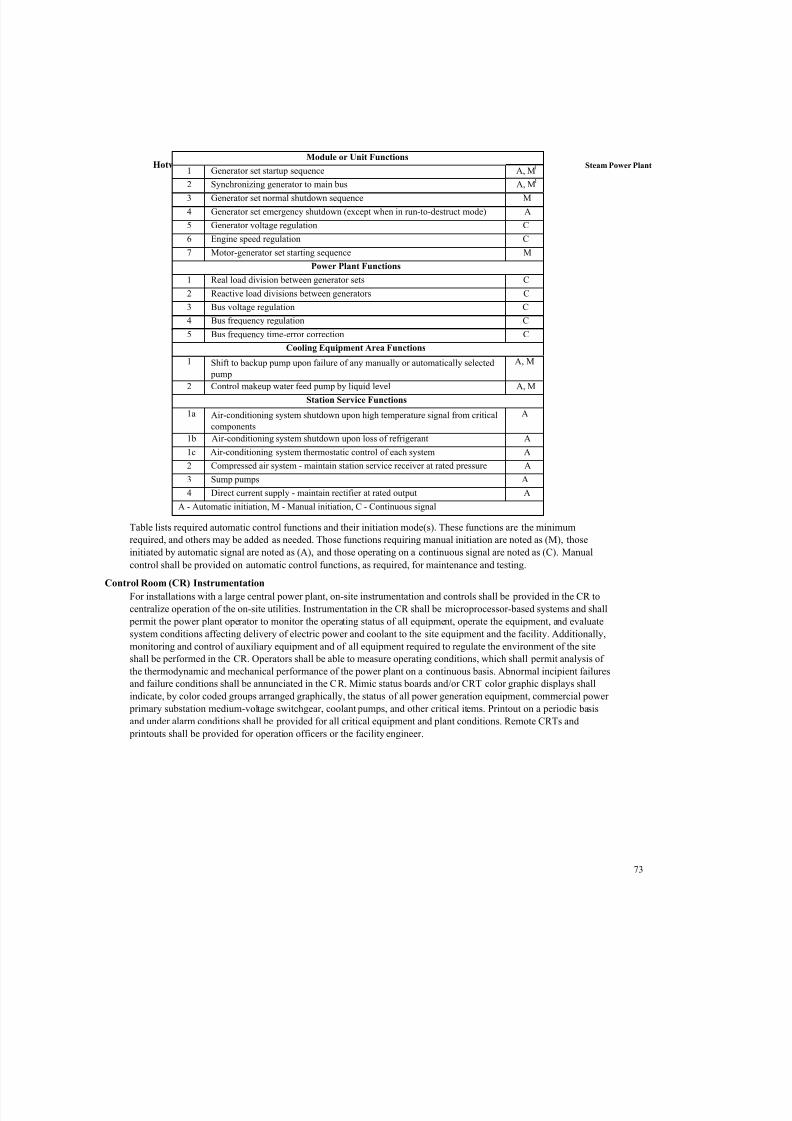
7/27/2019 Thermal Power plant Unit-2-58.docx
http://slidepdf.com/reader/full/thermal-power-plant-unit-2-58docx 55/65
Hotwell Steam Power Plant
73
Table lists required automatic control functions and their initiation mode(s). These functions are the minimum
required, and others may be added as needed. Those functions requiring manual initiation are noted as (M), those
initiated by automatic signal are noted as (A), and those operating on a continuous signal are noted as (C). Manual
control shall be provided on automatic control functions, as required, for maintenance and testing.
Control Room (CR) Instrumentation
For installations with a large central power plant, on-site instrumentation and controls shall be provided in the CR to
centralize operation of the on-site utilities. Instrumentation in the CR shall be microprocessor-based systems and shall
permit the power plant operator to monitor the operating status of all equipment, operate the equipment, and evaluate
system conditions affecting delivery of electric power and coolant to the site equipment and the facility. Additionally,
monitoring and control of auxiliary equipment and of all equipment required to regulate the environment of the site
shall be performed in the CR. Operators shall be able to measure operating conditions, which shall permit analysis of
the thermodynamic and mechanical performance of the power plant on a continuous basis. Abnormal incipient failures
and failure conditions shall be annunciated in the CR. Mimic status boards and/or CRT color graphic displays shall
indicate, by color coded groups arranged graphically, the status of all power generation equipment, commercial power
primary substation medium-voltage switchgear, coolant pumps, and other critical items. Printout on a periodic basis
and under alarm conditions shall be provided for all critical equipment and plant conditions. Remote CRTs and
printouts shall be provided for operation officers or the facility engineer.
Module or Unit Functions
1 Generator set startup sequence A, M1
2 Synchronizing generator to main bus A, M1
3 Generator set normal shutdown sequence M
4 Generator set emergency shutdown (except when in run-to-destruct mode) A
5 Generator voltage regulation C
6 Engine speed regulation C
7 Motor-generator set starting sequence M
Power Plant Functions
1 Real load division between generator sets C
2 Reactive load divisions between generators C
3 Bus voltage regulation C
4 Bus frequency regulation C
5 Bus frequency time-error correction C
Cooling Equipment Area Functions
1 Shift to backup pump upon failure of any manually or automatically selected
pump
A, M
2 Control makeup water feed pump by liquid level A, M
Station Service Functions
1a Air-conditioning system shutdown upon high temperature signal from critical
components
A
1b Air-conditioning system shutdown upon loss of refrigerant A
1c Air-conditioning system thermostatic control of each system A
2 Compressed air system - maintain station service receiver at rated pressure A
3 Sump pumps A
4 Direct current supply - maintain rectifier at rated output A
A - Automatic initiation, M - Manual initiation, C - Continuous signal
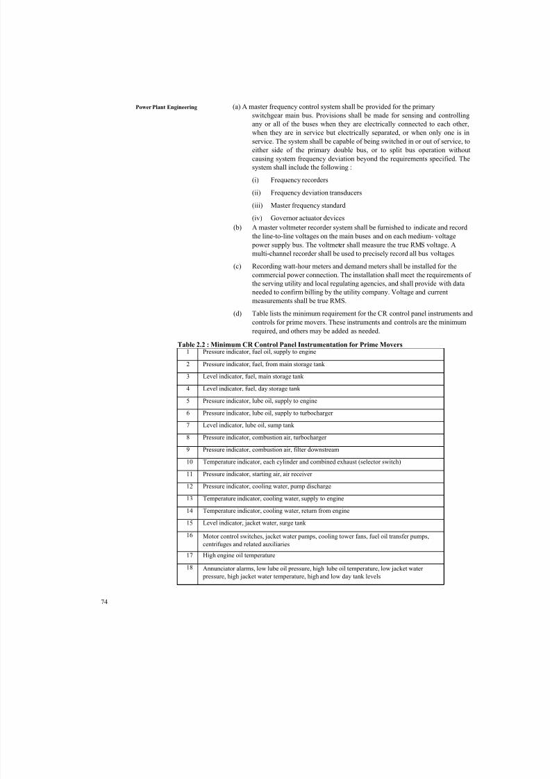
7/27/2019 Thermal Power plant Unit-2-58.docx
http://slidepdf.com/reader/full/thermal-power-plant-unit-2-58docx 56/65
74
Power Plant Engineering (a) A master frequency control system shall be provided for the primary
switchgear main bus. Provisions shall be made for sensing and controlling
any or all of the buses when they are electrically connected to each other,
when they are in service but electrically separated, or when only one is inservice. The system shall be capable of being switched in or out of service, to
either side of the primary double bus, or to split bus operation without
causing system frequency deviation beyond the requirements specified. The
system shall include the following :
(i) Frequency recorders
(ii) Frequency deviation transducers
(iii) Master frequency standard
(iv) Governor actuator devices
(b) A master voltmeter recorder system shall be furnished to indicate and record
the line-to-line voltages on the main buses and on each medium- voltage
power supply bus. The voltmeter shall measure the true RMS voltage. A
multi-channel recorder shall be used to precisely record all bus voltages.
(c) Recording watt-hour meters and demand meters shall be installed for thecommercial power connection. The installation shall meet the requirements of
the serving utility and local regulating agencies, and shall provide with data
needed to confirm billing by the utility company. Voltage and current
measurements shall be true RMS.
(d) Table lists the minimum requirement for the CR control panel instruments and
controls for prime movers. These instruments and controls are the minimum
required, and others may be added as needed.
Table 2.2 : Minimum CR Control Panel Instrumentation for Prime Movers1 Pressure indicator, fuel oil, supply to engine
2 Pressure indicator, fuel, from main storage tank
3 Level indicator, fuel, main storage tank
4 Level indicator, fuel, day storage tank
5 Pressure indicator, lube oil, supply to engine
6 Pressure indicator, lube oil, supply to turbocharger
7 Level indicator, lube oil, sump tank
8 Pressure indicator, combustion air, turbocharger
9 Pressure indicator, combustion air, filter downstream
10 Temperature indicator, each cylinder and combined exhaust (selector switch)
11 Pressure indicator, starting air, air receiver
12 Pressure indicator, cooling water, pump discharge
13 Temperature indicator, cooling water, supply to engine
14 Temperature indicator, cooling water, return from engine
15 Level indicator, jacket water, surge tank
16 Motor control switches, jacket water pumps, cooling tower fans, fuel oil transfer pumps,
centrifuges and related auxiliaries
17 High engine oil temperature
18 Annunciator alarms, low lube oil pressure, high lube oil temperature, low jacket water
pressure, high jacket water temperature, high and low day tank levels
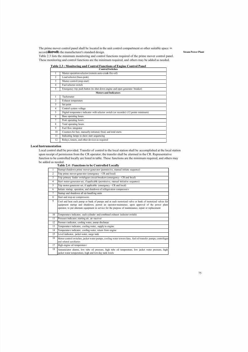
7/27/2019 Thermal Power plant Unit-2-58.docx
http://slidepdf.com/reader/full/thermal-power-plant-unit-2-58docx 57/65
Hotwell Steam Power Plant
75
The prime mover control panel shall be located in the unit control compartment or other suitable space in
accordance with the manufacturer's standard design.
Table 2.3 lists the minimum monitoring and control functions required of the prime mover control panel.
These monitoring and control functions are the minimum required, and others may be added as needed.
Local Instrumentation
Local control shall be provided. Transfer of control to the local station shall be accomplished at the local station
upon receipt of permission from the CR operator; the transfer shall be alarmed in the CR. Representative
function to be controlled locally are listed in table. These functions are the minimum required, and others may
be added as needed.Table 2.4 : Functions to be Controlled Locally
Table 2.3 : Monitoring and Control Functions of Engine Control PanelControl Switches
1 Master operation selector (remote-auto-crank-fire-oil)
2 Load selector (base-peak)
3 Master control (stop-start)
4 Fuel selector switch
5 Emergency trip push button (to shut down engine and open generator breaker)
Motors and Indicators
1 Tachometer
2 Exhaust temperature
3 Set point
4 Control system voltage
5 Digital temperature indicator with selector switch (or recorder) (12 points minimum)
6 Base operating hours
7 Peak operating hours
8 Total operating hours
9 Fuel flow integrator
10 Counters for fast, manually initiated, fired, and total starts
11 Indicating lamps to show start sequencing
12 Relays, timers, and other devices as required
1 Startup/shutdown prime mover-generator (permissive, manual initiate sequence)
2 Trip prime mover-generator (emergency - CR and local)
3 Trip primary feeder switchgear circuit breakers (emergency - CR and local)
4 Start motor-generator set, if applicable (permissive, manual initiative sequence)
5 Trip motor-generator set, if applicable (emergency - CR and local)
6 Initiate startup, operation, and shutdown of refrigeration compressors
7 Startup and shutdown all air-handl ing units
8 Start and stop air compressors
9 Cool and heat each pump or bank of pumps and at each motorized valve or bank of motorized valves for
equipment startup and shutdown; permit an operator-maintainer, upon approval of the power plant
operator, to put alternate equipment in service for the purpose of maintenance, repair or replacement
10 Temperature indicator, each cylinder and combined exhaust (selector switch)
11 Pressure indicator, starting air, air receiver
12 Pressure indicator, cooling water, pump discharge
13 Temperature indicator, cooling water, supply to engine
14 Temperature indicator, cooling water, return from engine
15 Level indicator, jacket water, surge tank
16 Motor control switches, jacket water pumps, cooling water towers fans, fuel oil transfer pumps, centrifugesand related auxiliaries
17 High engine oil temperature
18 Annuniciator alarms, low tube oil pressure, high tube oil temperature, low jacket water pressure, high
jacket water temperature, high and low day tank levels
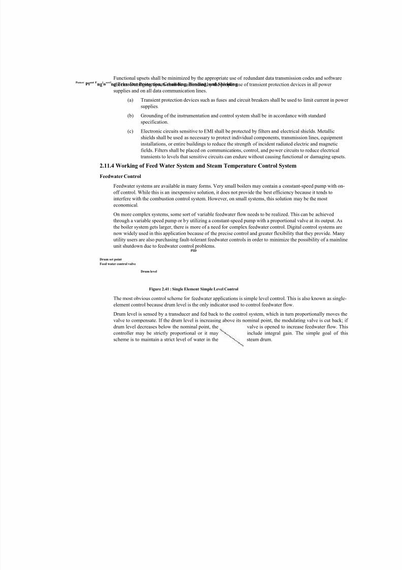
7/27/2019 Thermal Power plant Unit-2-58.docx
http://slidepdf.com/reader/full/thermal-power-plant-unit-2-58docx 58/65
PowerPl
ant Eng
in
eering Transient Protection, Grounding, Bonding, and Shielding
Functional upsets shall be minimized by the appropriate use of redundant data transmission codes and software
checks. Damaging upsets shall be minimized by the proper use of transient protection devices in all power
supplies and on all data communication lines.
(a) Transient protection devices such as fuses and circuit breakers shall be used to limit current in power
supplies.
(b) Grounding of the instrumentation and control system shall be in accordance with standard
specification.
(c) Electronic circuits sensitive to EMI shall be protected by filters and electrical shields. Metallic
shields shall be used as necessary to protect individual components, transmission lines, equipment
installations, or entire buildings to reduce the strength of incident radiated electric and magnetic
fields. Filters shall be placed on communications, control, and power circuits to reduce electrical
transients to levels that sensitive circuits can endure without causing functional or damaging upsets.
2.11.4 Working of Feed Water System and Steam Temperature Control System
Feedwater Control
Feedwater systems are available in many forms. Very small boilers may contain a constant-speed pump with on-
off control. While this is an inexpensive solution, it does not provide the best efficiency because it tends tointerfere with the combustion control system. However, on small systems, this solution may be the most
economical.
On more complex systems, some sort of variable feedwater flow needs to be realized. This can be achieved
through a variable speed pump or by utilizing a constant-speed pump with a proportional valve at its output. As
the boiler system gets larger, there is more of a need for complex feedwater control. Digital control systems are
now widely used in this application because of the precise control and greater flexibility that they provide. Many
utility users are also purchasing fault-tolerant feedwater controls in order to minimize the possibility of a mainline
unit shutdown due to feedwater control problems.PID
Drum set point
Feed water control valve
Drum level
Figure 2.41 : Single Element Simple Level Control
The most obvious control scheme for feedwater applications is simple level control. This is also known as single-
element control because drum level is the only indicator used to control feedwater flow.
Drum level is sensed by a transducer and fed back to the control system, which in turn proportionally moves the
valve to compensate. If the drum level is increasing above its nominal point, the modulating valve is cut back; if
drum level decreases below the nominal point, the valve is opened to increase feedwater flow. This
controller may be strictly proportional or it may include integral gain. The simple goal of this
scheme is to maintain a strict level of water in the steam drum.
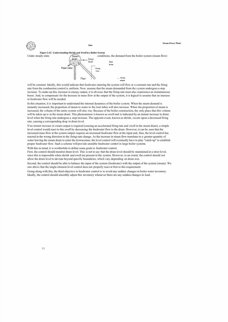
7/27/2019 Thermal Power plant Unit-2-58.docx
http://slidepdf.com/reader/full/thermal-power-plant-unit-2-58docx 59/65
77
Figure 2.42 : Understanding Shrink and Swell in a Boiler System
Under steady-state conditions, the demand from the boiler system (steam flow)
will be constant. Ideally, this would indicate that feedwater entering the system will flow at a constant rate and the firing
rate from the combustion control is uniform. Now, assume that the steam demanded from the system undergoes a step
increase. To make up this increase in energy output, it is obvious that the firing rate must also experience an instantaneous
boost. And, to compensate for the increase in mass flow at the output of the system, it is logical to assume that an increase
in feedwater flow will be needed.
In this situation, it is important to understand the internal dynamics of the boiler system. When the steam demand is
instantly increased, the proportion of steam to water in the riser tubes will also increase. When the proportion of steam is
increased, the volume of the entire system will also rise. Because of the boiler construction, the only place that this volume
will be taken up is in the steam drum. This phenomenon is known as swell and is indicated by an instant increase in drum
level when the firing rate undergoes a step increase. The opposite event, known as shrink, occurs upon a decreased firing
rate, causing a corresponding drop in drum level.
If an instant increase in steam output is required (causing an accelerated firing rate and swell in the steam drum), a simple
level control would react to this swell by decreasing the feedwater flow to the drum. However, it can be seen that the
increased mass flow at the system output requires an increased feedwater flow at the input and, thus, the level control has
reacted in the wrong direction to the firing-rate change. As the increase in steam flow translates to a greater quantity of
water leaving the steam drum to enter the downcomer, the level control will eventually have to play "catch-up" to establish
proper feedwater flow. Such a scheme will provide unstable feedwater control in large boiler systems.
With this in mind, it is worthwhile to define some goals to feedwater control.
First, the control should monitor drum level. This is not to say that the drum level should be maintained at a strict level,
since this is impossible when shrink and swell are present in the system. However, to an extent, the control should not
allow the drum level to deviate beyond specific boundaries, which vary depending on drum size.
Second, the control should be able to balance the input of the system (feedwater) with the output of the system (steam). Wesaw above that the single-element level control does not properly react at first to this requirement.
Going along with this, the third objective to feedwater control is to avoid any sudden changes in boiler water inventory.
Ideally, the control should smoothly adjust this inventory whenever there are any sudden changes in load.
Steam Power Plant Flowt
Firing
Area
Mud
drum
n _ Steam
output
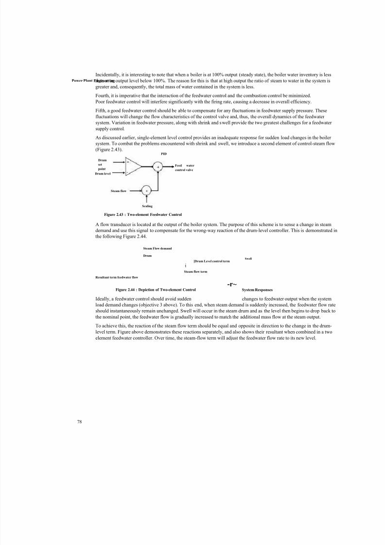
7/27/2019 Thermal Power plant Unit-2-58.docx
http://slidepdf.com/reader/full/thermal-power-plant-unit-2-58docx 60/65
Power Plant Engineering
78
Incidentally, it is interesting to note that when a boiler is at 100% output (steady state), the boiler water inventory is less
than at an output level below 100%. The reason for this is that at high output the ratio of steam to water in the system is
greater and, consequently, the total mass of water contained in the system is less.
Fourth, it is imperative that the interaction of the feedwater control and the combustion control be minimized.
Poor feedwater control will interfere significantly with the firing rate, causing a decrease in overall efficiency.
Fifth, a good feedwater control should be able to compensate for any fluctuations in feedwater supply pressure. These
fluctuations will change the flow characteristics of the control valve and, thus, the overall dynamics of the feedwater
system. Variation in feedwater pressure, along with shrink and swell provide the two greatest challenges for a feedwater
supply control.
As discussed earlier, single-element level control provides an inadequate response for sudden load changes in the boiler
system. To combat the problems encountered with shrink and swell, we introduce a second element of control-steam flow
(Figure 2.43).PID
A flow transducer is located at the output of the boiler system. The purpose of this scheme is to sense a change in steam
demand and use this signal to compensate for the wrong-way reaction of the drum-level controller. This is demonstrated in
the following Figure 2.44.
Steam Flow demand
Drum
[Drum Level control term
iSteam flow term
Resultant term feedwater flow
Figure 2.44 : Depiction of Two-element Control System Responses
Ideally, a feedwater control should avoid sudden changes to feedwater output when the system
load demand changes (objective 3 above). To this end, when steam demand is suddenly increased, the feedwater flow rate
should instantaneously remain unchanged. Swell will occur in the steam drum and as the level then begins to drop back to
the nominal point, the feedwater flow is gradually increased to match the additional mass flow at the steam output.
To achieve this, the reaction of the steam flow term should be equal and opposite in direction to the change in the drum-
level term. Figure above demonstrates these reactions separately, and also shows their resultant when combined in a two
element feedwater controller. Over time, the steam-flow term will adjust the feedwater flow rate to its new level.
Drum
set
point
Drum level
Feed water
control valve
Steam flow
Scaling
Figure 2.43 : Two-element Feedwater Control
Swell
-r~

7/27/2019 Thermal Power plant Unit-2-58.docx
http://slidepdf.com/reader/full/thermal-power-plant-unit-2-58docx 61/65

7/27/2019 Thermal Power plant Unit-2-58.docx
http://slidepdf.com/reader/full/thermal-power-plant-unit-2-58docx 62/65
80
Power Plant Engineering A rule of thumb says that increasing the live steam temperature by 10°C will
increase the efficiency of a 400 MW unit by approximately 0.25 per cent, leading to
large fuel cost savings.
Load-following Capability
Improved steam temperature control improves the boiler stability, which can improve
the load-following capability of the plant significantly. Improving the boiler stability in
general can, of course, lead to improved load-following capability, but it is crucial in
so-called special situations such as load changes, start/stop of coal mills, soot blowing,
fault situations, etc.
Availability
The improved overall stability and the resulting reduced probability of forced plant
outage is an indirect advantage of improving the steam temperature control.
Nevertheless, it is an important advantage, e.g. a forced outage of a coal fired base-load
unit will imply additional fuel costs for restart, lack of power sales, increased wear of
the plant and reduced availability. The costs of a forced outage will be dependent on
plant size, time of occurrence, duration, but will most often be of major economic
significance.
2.11.6 Superheater Control
The superheaters form part of a multivariable system. A simple example of an existing
scheme for steam temperature control is shown in Figure. This is a cascade control based on
fixed PID controllers in which the controlled variable is the outlet temperature. The inner loop
is required to reject temperature disturbances originating upstream. The inner loop is, of
course, much faster that the outer loop. Due to the load dependent dynamic and gain
variations, a strategy based on fixed controllers, like that shown in
Figure 2.46 : Pi-based Control Strategy
Performance can be improved relatively easily by introducing load-dependent gain scheduling
in the inner control loop. In special cases where the superheater operation is close to the wet
steam range, gain scheduling in the outer loop might also be beneficial. Furthermore,
introduction of feed forward disturbance compensation may also improve performance, e.g.
using fuel flow as an indicator of combustion disturbances.
2.11.7 Feedforward Control
The purpose of the feedforward control structure from the load demand to the feedwater and
fuel demand is to feed the correct amount of feedwater and fuel to the boiler. From a static
point of view the required input is known for each parameter to operate the boiler at a certain
load point. This is given through the gain = 1 part of the feedforward
Figure 2.46 can only be well tuned in one operating point.

7/27/2019 Thermal Power plant Unit-2-58.docx
http://slidepdf.com/reader/full/thermal-power-plant-unit-2-58docx 63/65
81
structure. The other part of the feedforward is a filter which ensures that the feedwater Steam P
°wer Plant
and the fuel are fed to the boiler in a dynamically optimal way thus ensuring that no
control fault arise - neither for the temperature nor for the live steam pressure during
load changes. Because of the presence of large time constants in the boiler due to the
large metal masses and delays in the firing system there is a limitation to how hard the
feedback loops can be tuned. This implies that if it is required to operate the plant at
large load gradients or it is desired to stress the plant as little as possible the presence
and correct tuning of the feedforward part is very important.
2.11.8 Feedback Control
The purpose of the feedback control is to reject disturbances which mostly originate from the furnace during normal
operation (mainly due to changes in fuel flow and quality). The feedback control consists of a temperature and a pressure
control loop. The enthalpy at the evaporator outlet is PI controlled in the inner loop. The reason for controlling the
enthalpy at the evaporator outlet instead of the steam temperature is that in this way non-linearities originating from the
steam characteristics are automatically incorporated. The proportional and integral part of the PI controllers must be
scheduled according to the actual load point since the gain and time constant of the boiler are highly dependent on the load
point (because of the change in steam flow).
The live steam pressure is controlled by a single PID-based control loop. For this loop the parameters of the PID controller must also be dependent on the actual load point.
Since the boiler process is fully connected (the feedwater flow and the fuel flow affect both the steam temperature and the
live steam pressure) it is important to introduce a decoupling network between the two feedback loops. Consequently, the
two feedback loops can be tuned independently and with as high a bandwidth as possible since no oscillatory modes will
arise between the two feedback loops.
2.11.9 Advanced Evaporator Control
To estimate the boiler dynamics for the purpose of performing model-based tuning, an open-loop test must be performed
or estimation performed in closed loop. Both tasks might be difficult. Furthermore, for plant equipped with non-
programmable control systems the implementation of the conventional way is quite tedious. To overcome these
difficulties, an alternative concept has been developed. The objective is to improve the load-following capability of
existing power plant units. During fast load changes, the major problem is to keep certain critical variables (e.g. steam
temperature and steam pressure) within predefined limits, as excessive deviations will seriously affect the lifetime of the
components or cause a trip. One way of improving the load-following capability of power plants is to improve the control
of these critical variables.
Figure 2.47 : Scheduled LQG Controller with Feedwater Acton from
Load Demand Signal, as a Complement to an Existing Boiler Control
System
7/27/2019 Thermal Power plant Unit-2-58.docx
http://slidepdf.com/reader/full/thermal-power-plant-unit-2-58docx 64/65
82
Power Plant Engineering SAQ 2
(a) What is a super-heater? What are its types? Describe any one of them.
(b) What is a feed water heater? Explain its advantages.
(c) What is a furnace? What are its types?
(d) Explain advantages and disadvantages of different types of furnaces.
SAQ 3
(a) How do you measure the performance of a boiler? Explain.
(b) Describe the various types of performance measurement of boilers.
(c) What is a steam turbine? How do they classify? Explain the working of any
one steam turbine.
(d) Explain the various components of steam turbine and their functions.
(e) Describe the advantages and disadvantages of steam turbines.
SAQ 4
(a) What is a condenser? What are the various components of condensers?
Explain their functions.
(b) What is a cooling tower? What are the various types of cooling towers?
(c) Describe the working of natural draft cooling tower.
(d) Explain the different control systems of steam power plant.
2.12 SUMMARY
Steam power plants are located at the water and coal available places. Steam is utilized to
run the turbines, in turn gives the power to generator and generator produces the electricity,
the electricity is utilized for lighting, running the industries, for lighting of offices, schools,
etc. Boiler is an important component of the power plants, it produces the steam.
2.13 KEY WORDS
Cooling Tower Condenser
: Cooling towers do the job of
decreasing the temperature
of the cooling water after
condensing the steam in the
condenser.
: It improves the efficiency
of the power plant by
decreasing the exhaust pressure of the steam
below atmosphere.

7/27/2019 Thermal Power plant Unit-2-58.docx
http://slidepdf.com/reader/full/thermal-power-plant-unit-2-58docx 65/65
2.14 ANSWERS TO SAQs ____________________________ Steam Power Plant
Refer the preceding text for all the Answers to SAQs.