Embed Size (px)
Citation preview
Thermal Management SolutionsCreated to perform when the heat is on
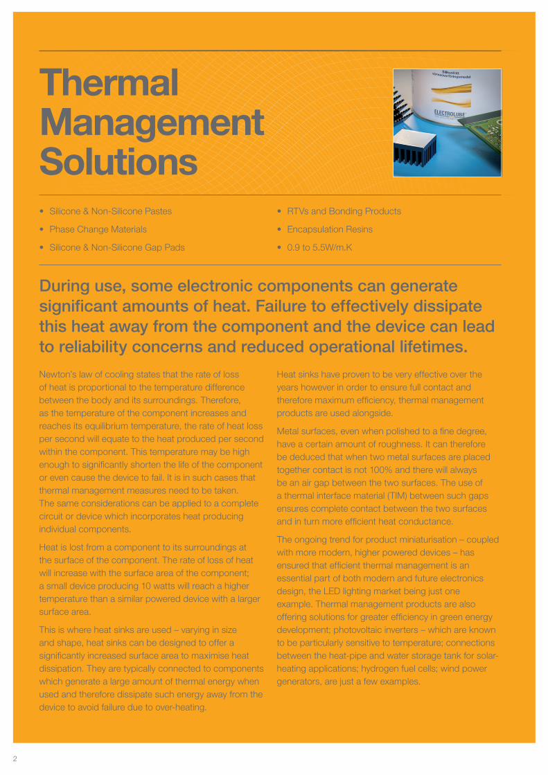
During use, some electronic components can generate significant amounts of heat. Failure to effectively dissipate this heat away from the component and the device can lead to reliability concerns and reduced operational lifetimes.
Newton’s law of cooling states that the rate of loss of heat is proportional to the temperature difference between the body and its surroundings. Therefore, as the temperature of the component increases and reaches its equilibrium temperature, the rate of heat loss per second will equate to the heat produced per second within the component. This temperature may be high enough to significantly shorten the life of the component or even cause the device to fail. It is in such cases that thermal management measures need to be taken. The same considerations can be applied to a complete circuit or device which incorporates heat producing individual components.
Heat is lost from a component to its surroundings at the surface of the component. The rate of loss of heat will increase with the surface area of the component; a small device producing 10 watts will reach a higher temperature than a similar powered device with a larger surface area.
This is where heat sinks are used – varying in size and shape, heat sinks can be designed to offer a significantly increased surface area to maximise heat dissipation. They are typically connected to components which generate a large amount of thermal energy when used and therefore dissipate such energy away from the device to avoid failure due to over-heating.
Heat sinks have proven to be very effective over the years however in order to ensure full contact and therefore maximum efficiency, thermal management products are used alongside.
Metal surfaces, even when polished to a fine degree, have a certain amount of roughness. It can therefore be deduced that when two metal surfaces are placed together contact is not 100% and there will always be an air gap between the two surfaces. The use of a thermal interface material (TIM) between such gaps ensures complete contact between the two surfaces and in turn more efficient heat conductance.
The ongoing trend for product miniaturisation – coupled with more modern, higher powered devices – has ensured that efficient thermal management is an essential part of both modern and future electronics design, the LED lighting market being just one example. Thermal management products are also offering solutions for greater efficiency in green energy development; photovoltaic inverters – which are known to be particularly sensitive to temperature; connections between the heat-pipe and water storage tank for solar-heating applications; hydrogen fuel cells; wind power generators, are just a few examples.
• Silicone & Non-Silicone Pastes
• Phase Change Materials
• Silicone & Non-Silicone Gap Pads
• RTVs and Bonding Products
• Encapsulation Resins
• 0.9 to 5.5W/m.K
Thermal Management Solutions
2
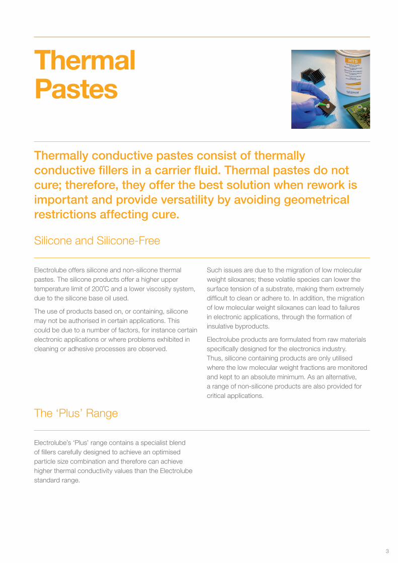
Thermally conductive pastes consist of thermally conductive fillers in a carrier fluid. Thermal pastes do not cure; therefore, they offer the best solution when rework is important and provide versatility by avoiding geometrical restrictions affecting cure.
Thermal Pastes
Electrolube offers silicone and non-silicone thermal pastes. The silicone products offer a higher upper temperature limit of 200˚C and a lower viscosity system, due to the silicone base oil used.
The use of products based on, or containing, silicone may not be authorised in certain applications. This could be due to a number of factors, for instance certain electronic applications or where problems exhibited in cleaning or adhesive processes are observed.
Such issues are due to the migration of low molecular weight siloxanes; these volatile species can lower the surface tension of a substrate, making them extremely difficult to clean or adhere to. In addition, the migration of low molecular weight siloxanes can lead to failures in electronic applications, through the formation of insulative byproducts.
Electrolube products are formulated from raw materials specifically designed for the electronics industry. Thus, silicone containing products are only utilised where the low molecular weight fractions are monitored and kept to an absolute minimum. As an alternative, a range of non-silicone products are also provided for critical applications.
Electrolube’s ‘Plus’ range contains a specialist blend of fillers carefully designed to achieve an optimised particle size combination and therefore can achieve higher thermal conductivity values than the Electrolube standard range.
Silicone and Silicone-Free
The ‘Plus’ Range
3
Electrolube’s ‘Xtra’ range of thermal products are enhanced versions of the non-silicone products HTC and HTCP. These ‘X’ versions are manufactured using one of the company’s proprietary technologies and possess the following benefits with almost no compromise in usability and viscosity: an increase in the comparative thermal conductivity, lower oil bleed and lower evaporation weight loss. HTCPX is mainly used as a gap filler and has been approved by one of the top manufacturers in the automotive industry.
The ‘Xtra’ range of products are also more resistant to humidity and thermal cycling (rapid changes in heating and cooling) than the standard range.
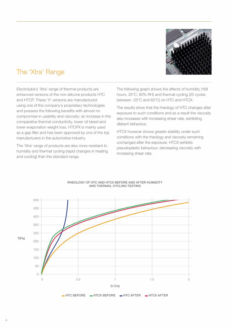
The following graph shows the effects of humidity (168 hours, 25°C, 90% RH) and thermal cycling (25 cycles between -25°C and 65°C) on HTC and HTCX.
The results show that the rheology of HTC changes after exposure to such conditions and as a result the viscosity also increases with increasing shear rate, exhibiting dilatant behaviour.
HTCX however shows greater stability under such conditions with the rheology and viscosity remaining unchanged after the exposure. HTCX exhibits pseudoplastic behaviour; decreasing viscosity with increasing shear rate.
The ‘Xtra’ Range
0 0.5 1 1.5 2
HTC BEFORE HTCX BEFORE HTC AFTER HTCX AFTER
RHEOLOGY OF HTC AND HTCX BEFORE AND AFTER HUMIDITY AND THERMAL CYCLING TESTING
500
450
400
350
250
200
150
100
50
0
D (1/s)
T(Pa)
4
Phase-ChangeMaterials Phase-Change Material
Product Bulk Thermal Conductivity (W/m K)
Thermal Resistance (˚C in2/W)
TPM350 3.50 0.026
TPM550 5.50 0.012
Phase change materials have been designed to combine the very low thermal resistance achieved using a thermal paste, with the stability of a cured or solid material, such as an RTV or gap pad. Their name is derived from their properties during use, changing state from a solid to a liquid and back again depending on the temperature of the application. Each phase change material will have its’ own softening temperature, at which the change of state
occurs. Once this temperature is reached, the ability of the phase change material to become softer allows the product to fully conform to the contours of the substrate, filling in the interface at a minimal bond line thickness. This in turn, results in very low thermal resistance and maximise the efficiency of heat transfer.
Phase change materials can be applied in a number of ways; the most convenient being a screen printing technique. In this application method, a phase change material containing a small amount of solvent is spread across a screen to deposit the desired thickness of material to the substrate. The solvent quickly evaporates leaving a firm paste behind at the interface. As the temperature increases, the material absorbs heat until it reaches its softening point and upon cooling reverts back to a firm paste again. Due to the stability of phase change materials during frequent temperature changes, the materials are resistant to problems such
as pump-out, commonly seen with non-curing thermal management materials.The stability of Electrolube’s phase change product, TPM350, during thermal cycling is shown in the graph below. This test was conducted on a Thermal Test Vehicle (TTV) using a Power Cycle Test, delivering a change in temperature from room temperature to 95˚C. Each cycle includes 12 min power heating and 8min cooling. A total of 1000 cycles were conducted and results showed good stability of the TPM350 throughout the duration of this test.
TPM Thermal Reliability Result By TTV Power Cycle Test
No
rmal
ised
The
rmal
Res
ista
nce
Cycles
5
Thermal Pastes
Application Options
As highlighted previously and with the exception of gap filling products, it is important that thermal interface materials (TIM) are applied in the thinnest layer possible to reduce the effects of thermal resistance. Therefore, the application of thermal pastes can be as important as the product selection stage.
Thermal pastes can be applied via a range of methods, either manual or automated.
i. Manual applications can be carried out using a roller, squeegee or spatula; often a roller is the best method to ensure a thin even film is deposited across the entire surface.
ii. Automated applications involve the use of specialist equipment. This usually consists of an applicator head where the material is fed to the applicator via dispensing equipment. Due to the viscosities of these materials, the dispensing equipment is usually a follower-plate system which connects to the thermal paste container as supplied. Please contact Electrolube where container dimensions are required.
Electrolube RTVs are supplied in ready-to-use cartridges and should be used with the TCR Gun applicator. Please contact Electrolube regarding bulk quantities.
These materials are often used for combined thermal transfer and fixing, therefore a thin layer should be applied and tests conducted to ensure the level of bonding achieved is sufficient for the application.
As these are moisture cure products, ambient humidity must be considered during application. Extreme conditions (very dry or very wet) will inhibit the cure and elevated temperatures will not speed up the process, unless humidity is also increased.
Encapsulation resins are two part systems which can be applied manually or through automated equipment. In all cases, the mixing procedure used should avoid the introduction of air; the introduction of air or moisture can affect the cure process of these materials as well as leave air voids in the cured product, which will significantly reduce the thermal conductivity.
i. Electrolube supply encapsulation resins in resin pack form; a pouch divided by a clip and rail which separates the Part A and B until the time of mixing. These packs are ideal for air-free mixing and are advised for all manual application of encapsulation resins. When supplied in an aluminium outer, this outer material should not be removed until immediately before use.
ii. Automated mixing and dispensing machines are also available either in benchtop or large scale models. Electrolube work with a number of local and international equipment manufacturers, please contact us for further information.
RTVs
Encapsulation Resins
6
Gap Pads
Thermal gap pads are used in place of traditional thermal interface materials (TIMs) such as a thermal paste or RTV. The main benefit of gap pads is that they offer a quick and easy application method, requiring minimal training for the operator and without the mess sometimes associated with a paste, grease or bonding product. In addition, they do not require the use of expensive dispensing machines and can easily be applied via a manual process.
Gap pads are often cut to size to fit the requirements of the specific interface application. They work in a similar manner to other TIMs, filling the small gaps and pockets between the two surfaces. As they cannot be applied in such a thin film as a thermal paste for example, they often provide a much thicker interface; pads thus work best for applications where there is a pressure exerted on the interface, minimising the bond line and ensuring maximum contact with the gap pad. The pressure forces the pad material into the air pockets, more effectively reducing the thermal resistance. The thermal resistance achieved will not match that of a thermal paste however.
Similar to thermal pastes, Electrolube’s gap pads are available in both silicone and non-silicone options, offering a range of performance requirements and meeting the demand for high temperature applications. Despite not meeting the same levels of efficiency on initial application, a gap pad may outperform a thermal paste under certain conditions. As the gap pad is a formed material, it does not move during thermal cycling and therefore does not experience the same pump-out issues that can be seen with some thermal pastes in rapidly changing thermal environments.
Product Bulk Thermal Conductivity (W/m K)
Thermal Resistance (˚C in2/W)
GP300 3.00 0.990
GP500 5.00 0.700
7
Electrolube offer a thermal bonding adhesive called TBS, as well as two RTV (room temperature vulcanising) products: TCOR and TCER.
TBS (Thermal Bonding System) is a two-part, high strength epoxy adhesive designed to bond a heat sink to the component. In addition to the mineral fillers, the adhesive contains small glass beads of controlled diameter: these allow for a set thickness of 200 microns to be achieved, providing optimal performance.
TCOR and TCER are Electrolube’s silicone RTV products. TCOR is an oxime-cure RTV, and TCER is an ethanol-cure version. TCER has the advantage that it is very low in viscosity and higher in thermal conductivity compared to TCOR; however, TCOR exhibits improved bond-strength properties.
For certain types of heat generating circuitry, it may be beneficial to encapsulate the device in a heat-sink enclosure using a thermally conductive potting compound. This method offers both heat dissipation and protection from the surrounding environment, such as high humidity or corrosive conditions.
Electrolube produces a variety of two-part encapsulation solutions utilising epoxy, polyurethane and silicone technologies:
ER2220 provides the highest level of thermal conductivity combined with environmental protection afforded from the encapsulation process. This highly-filled epoxy resin possesses very high thermal conductivity (1.54 W/m.K), resulting in a high viscosity (15,000 mPa s).
ER2183 is a lower viscosity version of ER2220 (5000 mPa s). The reduced filler content required to achieve this viscosity has little effect on the thermal conductivity performance: ER2183 is 67% lower in viscosity, but only exhibits a 28% decrease in thermal conductivity as a result (1.10 W/m.K).
UR5633 is a polyurethane encapsulation resin that offers very good thermal conductivity of 1.24 W/m.K. This is ideal for applications where thermal conductivity and a degree of flexibility are required.
SC2003 is a silicone encapsulation resin, offering a good level of thermal conductivity (0.80 W/m.K) over an exceptionally wide temperature range (-60 to +200°C). The product is thixotropic, making it ideal for applications where the resin should not flow through small gaps.
Adhesives and RTVs
Encapsulation Resins
Adhesives & Encapsulants
8
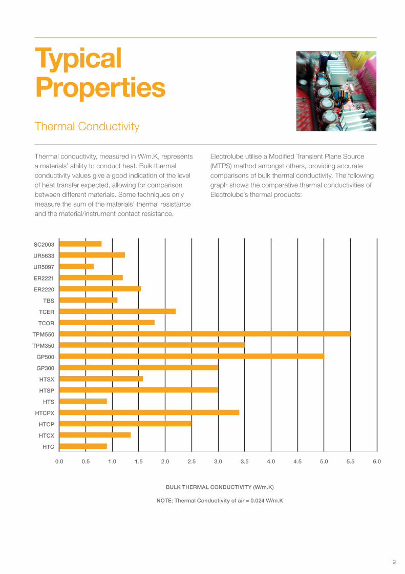
Thermal conductivity, measured in W/m.K, represents a materials’ ability to conduct heat. Bulk thermal conductivity values give a good indication of the level of heat transfer expected, allowing for comparison between different materials. Some techniques only measure the sum of the materials’ thermal resistance and the material/instrument contact resistance.
Electrolube utilise a Modified Transient Plane Source (MTPS) method amongst others, providing accurate comparisons of bulk thermal conductivity. The following graph shows the comparative thermal conductivities of Electrolube’s thermal products:
Thermal Conductivity
BULK THERMAL CONDUCTIVITY (W/m.K)
Typical Properties
NOTE: Thermal Conductivity of air = 0.024 W/m.K
THERMAL CONDUCTIVITY (W/m.K)
0.0 0.5 1.0 1.5 2.0 2.5 3.0 3.5 4.0 4.5 5.0 5.5 6.0
HTC
HTCX
HTCP
HTCPX
HTS
HTSP
HTSX
GP300
GP500
TPM350
TPM550
TCOR
TCER
TBS
ER2220
ER2221
UR5097
UR5633
SC2003
9
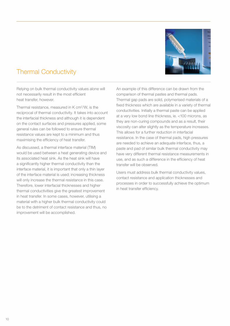
Relying on bulk thermal conductivity values alone will not necessarily result in the most efficient heat transfer, however.
Thermal resistance, measured in K cm2/W, is the reciprocal of thermal conductivity. It takes into account the interfacial thickness and although it is dependent on the contact surfaces and pressures applied, some general rules can be followed to ensure thermal resistance values are kept to a minimum and thus maximising the efficiency of heat transfer.
As discussed, a thermal interface material (TIM) would be used between a heat generating device and its associated heat sink. As the heat sink will have a significantly higher thermal conductivity than the interface material, it is important that only a thin layer of the interface material is used; increasing thickness will only increase the thermal resistance in this case. Therefore, lower interfacial thicknesses and higher thermal conductivities give the greatest improvement in heat transfer. In some cases, however, utilising a material with a higher bulk thermal conductivity could be to the detriment of contact resistance and thus, no improvement will be accomplished.
An example of this difference can be drawn from the comparison of thermal pastes and thermal pads. Thermal gap pads are solid, polymerised materials of a fixed thickness which are available in a variety of thermal conductivities. Initially a thermal paste can be applied at a very low bond line thickness, ie. <100 microns, as they are non-curing compounds and as a result, their viscosity can alter slightly as the temperature increases. This allows for a further reduction in interfacial resistance. In the case of thermal pads, high pressures are needed to achieve an adequate interface, thus, a paste and pad of similar bulk thermal conductivity may have very different thermal resistance measurements in use, and as such a difference in the efficiency of heat transfer will be observed.
Users must address bulk thermal conductivity values, contact resistance and application thicknesses and processes in order to successfully achieve the optimum in heat transfer efficiency.
Thermal Conductivity
10
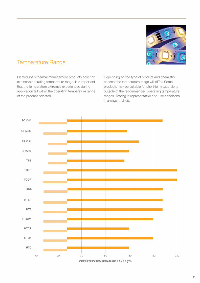
Electrolube’s thermal management products cover an extensive operating temperature range. It is important that the temperature extremes experienced during application fall within the operating temperature range of the product selected.
Depending on the type of product and chemistry chosen, the temperature range will differ. Some products may be suitable for short-term excursions outside of the recommended operating temperature ranges. Testing in representative end-use conditions is always advised.
Temperature Range
OPERATING TEMPERATURE RANGE (°C)
-70 -20 30 80 130 180 230
UR5633
TCER
HTCPX
ER2220
HTSP
HTCX
HTC
SC2003
TBS
HTS
ER2221
TCOR
HTCP
HTSX
11
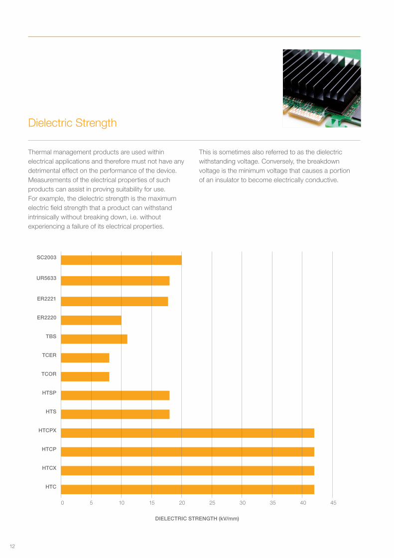
Thermal management products are used within electrical applications and therefore must not have any detrimental effect on the performance of the device. Measurements of the electrical properties of such products can assist in proving suitability for use. For example, the dielectric strength is the maximum electric field strength that a product can withstand intrinsically without breaking down, i.e. without experiencing a failure of its electrical properties.
This is sometimes also referred to as the dielectric withstanding voltage. Conversely, the breakdown voltage is the minimum voltage that causes a portion of an insulator to become electrically conductive.
Dielectric Strength
DIELECTRIC STRENGTH (kV/mm)
0 5 10 15 20 25 30 35 40 45
TCOR
TCER
TBS
ER2220
ER2221
UR5633
SC2003
HTSP
HTS
HTCPX
HTCP
HTCX
HTC
12
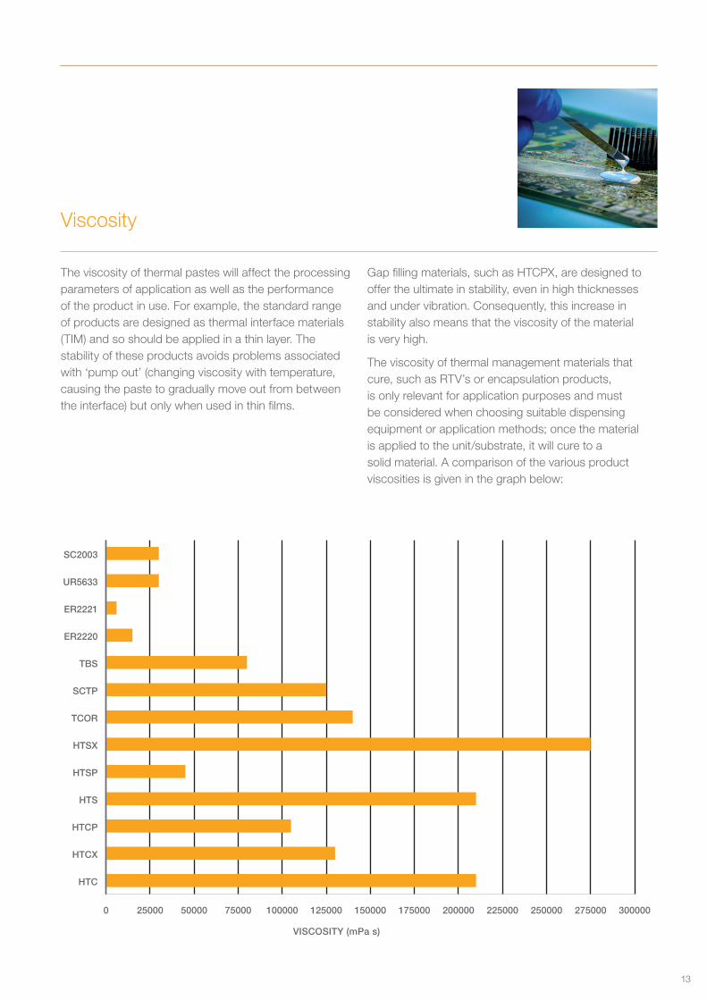
Viscosity
The viscosity of thermal pastes will affect the processing parameters of application as well as the performance of the product in use. For example, the standard range of products are designed as thermal interface materials (TIM) and so should be applied in a thin layer. The stability of these products avoids problems associated with ‘pump out’ (changing viscosity with temperature, causing the paste to gradually move out from between the interface) but only when used in thin films.
Gap filling materials, such as HTCPX, are designed to offer the ultimate in stability, even in high thicknesses and under vibration. Consequently, this increase in stability also means that the viscosity of the material is very high.
The viscosity of thermal management materials that cure, such as RTV’s or encapsulation products, is only relevant for application purposes and must be considered when choosing suitable dispensing equipment or application methods; once the material is applied to the unit/substrate, it will cure to a solid material. A comparison of the various product viscosities is given in the graph below:
VISCOSITY (mPa s)
0 25000 50000 75000 100000 125000 150000 175000 200000 225000 250000 275000 300000
HTC
HTCX
HTCP
HTS
HTSP
HTSX
TCOR
SCTP
TBS
ER2220
ER2221
UR5633
SC2003
13
MaximisingEfficiency
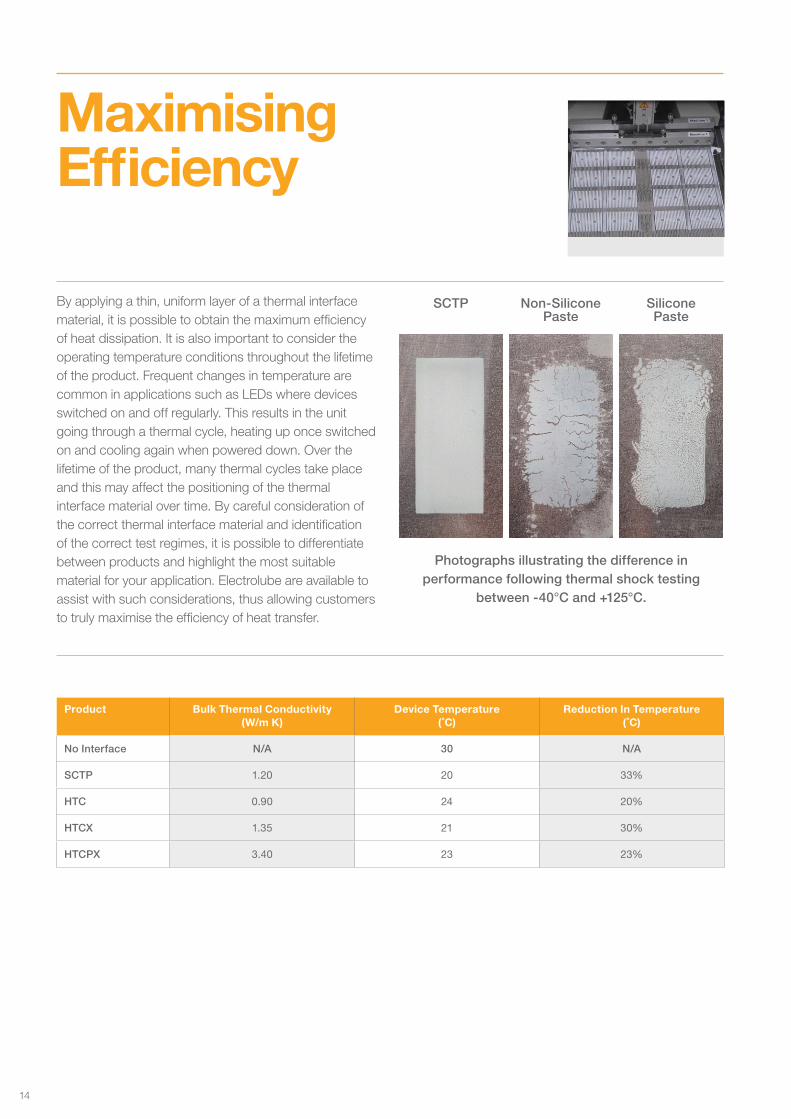
Photographs illustrating the difference in performance following thermal shock testing
between -40°C and +125°C.
By applying a thin, uniform layer of a thermal interface material, it is possible to obtain the maximum efficiency of heat dissipation. It is also important to consider the operating temperature conditions throughout the lifetime of the product. Frequent changes in temperature are common in applications such as LEDs where devices switched on and off regularly. This results in the unit going through a thermal cycle, heating up once switched on and cooling again when powered down. Over the lifetime of the product, many thermal cycles take place and this may affect the positioning of the thermal interface material over time. By careful consideration of the correct thermal interface material and identification of the correct test regimes, it is possible to differentiate between products and highlight the most suitable material for your application. Electrolube are available to assist with such considerations, thus allowing customers to truly maximise the efficiency of heat transfer.
SCTP Non-Silicone Paste
Silicone Paste
Product Bulk Thermal Conductivity (W/m K)
Device Temperature (˚C)
Reduction In Temperature (˚C)
No Interface N/A 30 N/A
SCTP 1.20 20 33%
HTC 0.90 24 20%
HTCX 1.35 21 30%
HTCPX 3.40 23 23%
14
The Product Range
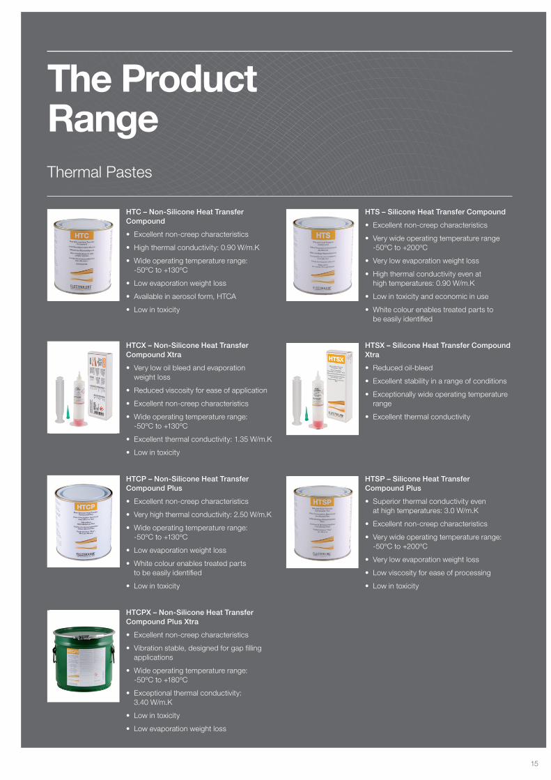
HTC – Non-Silicone Heat Transfer Compound
• Excellent non-creep characteristics
• High thermal conductivity: 0.90 W/m.K
• Wide operating temperature range: -50ºC to +130ºC
• Low evaporation weight loss
• Available in aerosol form, HTCA
• Low in toxicity
HTCX – Non-Silicone Heat Transfer Compound Xtra
• Very low oil bleed and evaporation weight loss
• Reduced viscosity for ease of application
• Excellent non-creep characteristics
• Wide operating temperature range: -50ºC to +130ºC
• Excellent thermal conductivity: 1.35 W/m.K
• Low in toxicity
HTCP – Non-Silicone Heat Transfer Compound Plus
• Excellent non-creep characteristics
• Very high thermal conductivity: 2.50 W/m.K
• Wide operating temperature range: -50ºC to +130ºC
• Low evaporation weight loss
• White colour enables treated parts to be easily identified
• Low in toxicity
HTCPX – Non-Silicone Heat Transfer Compound Plus Xtra
• Excellent non-creep characteristics
• Vibration stable, designed for gap filling applications
• Wide operating temperature range: -50ºC to +180ºC
• Exceptional thermal conductivity: 3.40 W/m.K
• Low in toxicity
• Low evaporation weight loss
HTS – Silicone Heat Transfer Compound
• Excellent non-creep characteristics
• Very wide operating temperature range -50ºC to +200ºC
• Very low evaporation weight loss
• High thermal conductivity even at high temperatures: 0.90 W/m.K
• Low in toxicity and economic in use
• White colour enables treated parts to be easily identified
HTSX – Silicone Heat Transfer Compound Xtra
• Reduced oil-bleed
• Excellent stability in a range of conditions
• Exceptionally wide operating temperature range
• Excellent thermal conductivity
HTSP – Silicone Heat Transfer Compound Plus
• Superior thermal conductivity even at high temperatures: 3.0 W/m.K
• Excellent non-creep characteristics
• Very wide operating temperature range: -50ºC to +200ºC
• Very low evaporation weight loss
• Low viscosity for ease of processing
• Low in toxicity
Thermal Pastes
15
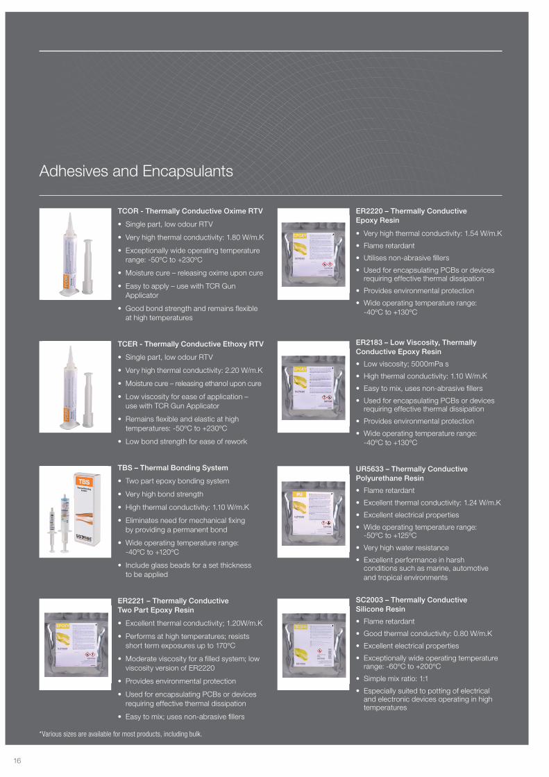
TCOR - Thermally Conductive Oxime RTV
• Single part, low odour RTV
• Very high thermal conductivity: 1.80 W/m.K
• Exceptionally wide operating temperature range: -50ºC to +230ºC
• Moisture cure – releasing oxime upon cure
• Easy to apply – use with TCR Gun Applicator
• Good bond strength and remains flexible at high temperatures
TCER - Thermally Conductive Ethoxy RTV
• Single part, low odour RTV
• Very high thermal conductivity: 2.20 W/m.K
• Moisture cure – releasing ethanol upon cure
• Low viscosity for ease of application – use with TCR Gun Applicator
• Remains flexible and elastic at high temperatures: -50ºC to +230ºC
• Low bond strength for ease of rework
TBS – Thermal Bonding System
• Two part epoxy bonding system
• Very high bond strength
• High thermal conductivity: 1.10 W/m.K
• Eliminates need for mechanical fixing by providing a permanent bond
• Wide operating temperature range: -40ºC to +120ºC
• Include glass beads for a set thickness to be applied
ER2221 – Thermally Conductive Two Part Epoxy Resin
• Excellent thermal conductivity; 1.20W/m.K
• Performs at high temperatures; resists short term exposures up to 170ºC
• Moderate viscosity for a filled system; low viscosity version of ER2220
• Provides environmental protection
• Used for encapsulating PCBs or devices requiring effective thermal dissipation
• Easy to mix; uses non-abrasive fillers
ER2220 – Thermally Conductive Epoxy Resin
• Very high thermal conductivity: 1.54 W/m.K
• Flame retardant
• Utilises non-abrasive fillers
• Used for encapsulating PCBs or devices requiring effective thermal dissipation
• Provides environmental protection
• Wide operating temperature range: -40ºC to +130ºC
ER2183 – Low Viscosity, Thermally Conductive Epoxy Resin
• Low viscosity; 5000mPa s
• High thermal conductivity: 1.10 W/m.K
• Easy to mix, uses non-abrasive fillers
• Used for encapsulating PCBs or devices requiring effective thermal dissipation
• Provides environmental protection
• Wide operating temperature range: -40ºC to +130ºC
UR5633 – Thermally Conductive Polyurethane Resin
• Flame retardant
• Excellent thermal conductivity: 1.24 W/m.K
• Excellent electrical properties
• Wide operating temperature range: -50ºC to +125ºC
• Very high water resistance
• Excellent performance in harsh conditions such as marine, automotive and tropical environments
SC2003 – Thermally Conductive Silicone Resin
• Flame retardant
• Good thermal conductivity: 0.80 W/m.K
• Excellent electrical properties
• Exceptionally wide operating temperature range: -60ºC to +200ºC
• Simple mix ratio: 1:1
• Especially suited to potting of electrical and electronic devices operating in high temperatures
Adhesives and Encapsulants
*Various sizes are available for most products, including bulk.
16
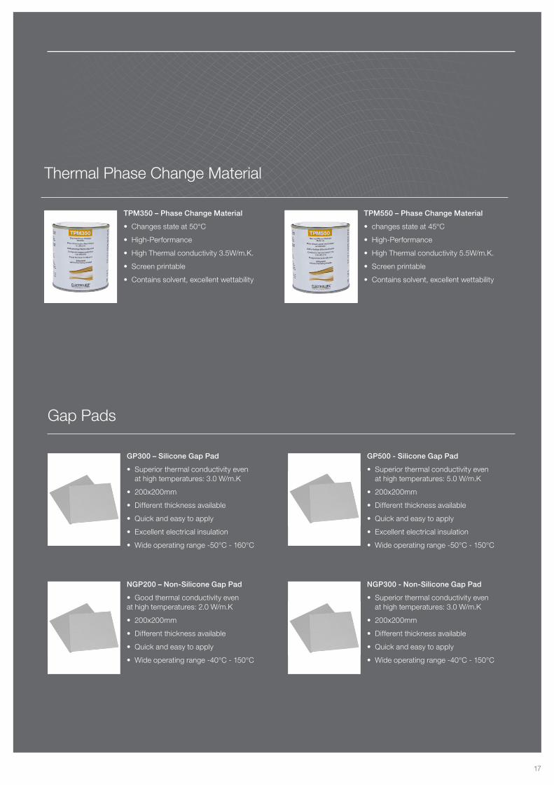
TPM350 – Phase Change Material
• Changes state at 50°C
• High-Performance
• High Thermal conductivity 3.5W/m.K.
• Screen printable
• Contains solvent, excellent wettability
TPM550 – Phase Change Material
• changes state at 45°C
• High-Performance
• High Thermal conductivity 5.5W/m.K.
• Screen printable
• Contains solvent, excellent wettability
GP300 – Silicone Gap Pad
• Superior thermal conductivity even at high temperatures: 3.0 W/m.K
• 200x200mm
• Different thickness available
• Quick and easy to apply
• Excellent electrical insulation
• Wide operating range -50°C - 160°C
GP500 - Silicone Gap Pad
• Superior thermal conductivity even at high temperatures: 5.0 W/m.K
• 200x200mm
• Different thickness available
• Quick and easy to apply
• Excellent electrical insulation
• Wide operating range -50°C - 150°C
Thermal Phase Change Material
Gap Pads
NGP200 – Non-Silicone Gap Pad
• Good thermal conductivity even at high temperatures: 2.0 W/m.K
• 200x200mm
• Different thickness available
• Quick and easy to apply
• Wide operating range -40°C - 150°C
NGP300 - Non-Silicone Gap Pad
• Superior thermal conductivity even at high temperatures: 3.0 W/m.K
• 200x200mm
• Different thickness available
• Quick and easy to apply
• Wide operating range -40°C - 150°C
17
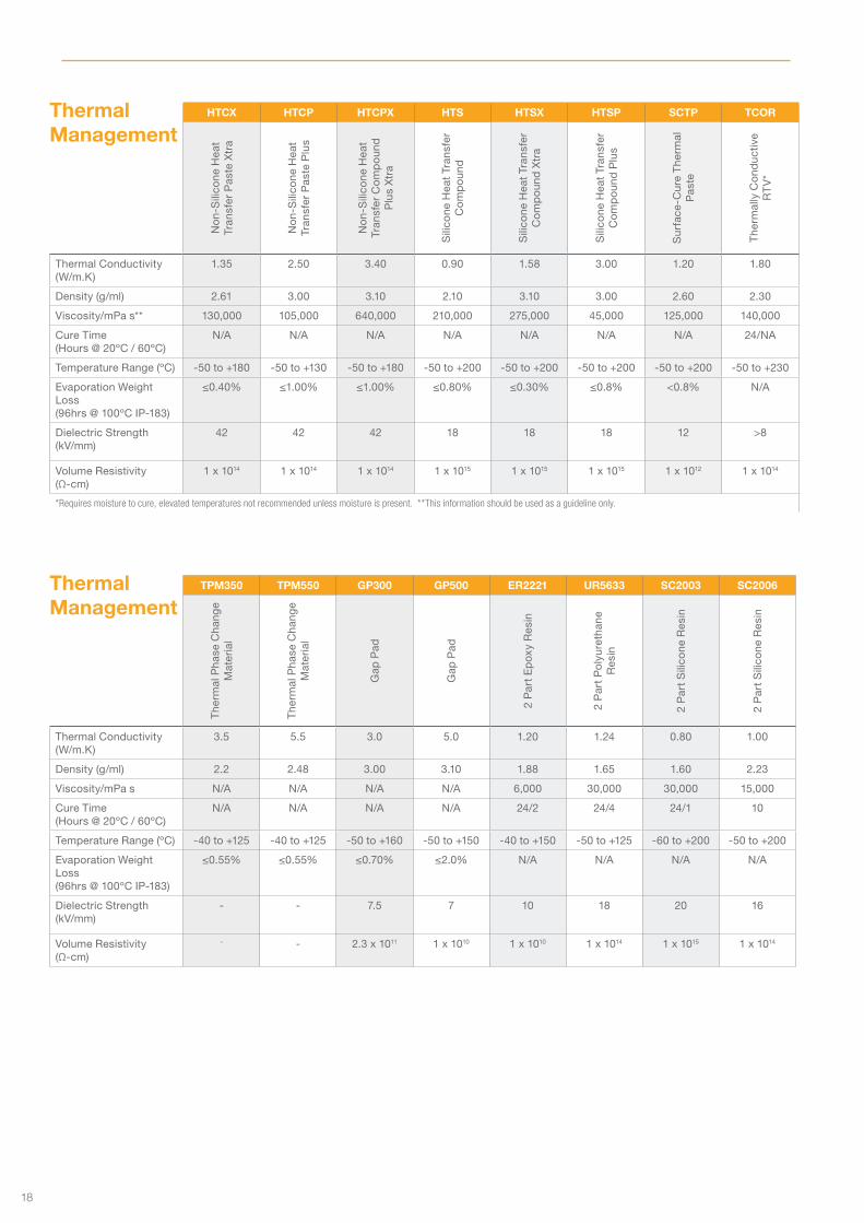
Thermal Management
HTCX HTCP HTCPX HTS HTSX HTSP SCTP TCOR
No
n-S
ilico
ne H
eat
Tran
sfer
Pas
te X
tra
No
n-S
ilico
ne H
eat
Tran
sfer
Pas
te P
lus
No
n-S
ilico
ne H
eat
Tran
sfer
Co
mp
oun
d
Plu
s X
tra
Sili
cone
Hea
t Tr
ansf
er
Co
mp
oun
d
Sili
cone
Hea
t Tr
ansf
er
Co
mp
oun
d X
tra
Sili
cone
Hea
t Tr
ansf
er
Co
mp
oun
d P
lus
Sur
face
-Cur
e T
herm
al
Pas
te
The
rmal
ly C
ond
uctiv
e R
TV
*
Thermal Conductivity (W/m.K)
1.35 2.50 3.40 0.90 1.58 3.00 1.20 1.80
Density (g/ml) 2.61 3.00 3.10 2.10 3.10 3.00 2.60 2.30
Viscosity/mPa s** 130,000 105,000 640,000 210,000 275,000 45,000 125,000 140,000
Cure Time (Hours @ 20ºC / 60ºC)
N/A N/A N/A N/A N/A N/A N/A 24/NA
Temperature Range (ºC) -50 to +180 -50 to +130 -50 to +180 -50 to +200 -50 to +200 -50 to +200 -50 to +200 -50 to +230
Evaporation Weight Loss (96hrs @ 100ºC IP-183)
≤0.40% ≤1.00% ≤1.00% ≤0.80% ≤0.30% ≤0.8% <0.8% N/A
Dielectric Strength (kV/mm)
42 42 42 18 18 18 12 >8
Volume Resistivity (Ω-cm)
1 x 10¹⁴ 1 x 10¹⁴ 1 x 10¹⁴ 1 x 10¹⁵ 1 x 10¹⁵ 1 x 10¹⁵ 1 x 10¹² 1 x 10¹⁴
*Requires moisture to cure, elevated temperatures not recommended unless moisture is present. **This information should be used as a guideline only.
Thermal Management
TPM350 TPM550 GP300 GP500 ER2221 UR5633 SC2003 SC2006
The
rmal
Pha
se C
hang
e M
ater
ial
The
rmal
Pha
se C
hang
e M
ater
ial
Gap
Pad
Gap
Pad
2 P
art
Ep
oxy
Res
in
2 P
art
Po
lyur
etha
ne
Res
in
2 P
art
Sili
cone
Res
in
2 P
art
Sili
cone
Res
in
Thermal Conductivity (W/m.K)
3.5 5.5 3.0 5.0 1.20 1.24 0.80 1.00
Density (g/ml) 2.2 2.48 3.00 3.10 1.88 1.65 1.60 2.23
Viscosity/mPa s N/A N/A N/A N/A 6,000 30,000 30,000 15,000
Cure Time (Hours @ 20ºC / 60ºC)
N/A N/A N/A N/A 24/2 24/4 24/1 10
Temperature Range (ºC) -40 to +125 -40 to +125 -50 to +160 -50 to +150 -40 to +150 -50 to +125 -60 to +200 -50 to +200
Evaporation Weight Loss (96hrs @ 100ºC IP-183)
≤0.55% ≤0.55% ≤0.70% ≤2.0% N/A N/A N/A N/A
Dielectric Strength (kV/mm)
- - 7.5 7 10 18 20 16
Volume Resistivity (Ω-cm)
- - 2.3 x 10¹¹ 1 x 10¹⁰ 1 x 10¹⁰ 1 x 10¹⁴ 1 x 10¹⁵ 1 x 10¹⁴
18
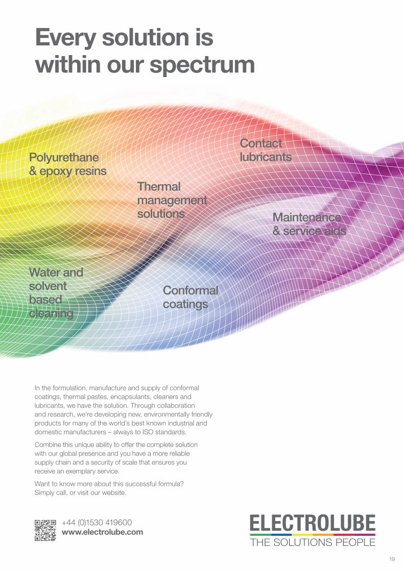
Polyurethane & epoxy resins
Conformal coatings
Contact lubricants
Maintenance & service aids
Water and solvent based cleaning
Thermal management solutions
Every solution is within our spectrum
In the formulation, manufacture and supply of conformal coatings, thermal pastes, encapsulants, cleaners and lubricants, we have the solution. Through collaboration and research, we’re developing new, environmentally friendly products for many of the world’s best known industrial and domestic manufacturers – always to ISO standards.
Combine this unique ability to offer the complete solution with our global presence and you have a more reliable supply chain and a security of scale that ensures you receive an exemplary service.
Want to know more about this successful formula? Simply call, or visit our website.
+44 (0)1530 419600 www.electrolube.com
19
UK Headquarters / Manufacturing
Ashby Park Coalfield Way Ashby de la Zouch Leicestershire LE65 1JR United Kingdom
T +44 (0)1530 419600 F +44 (0)1530 416640 E [email protected]
www.electrolube.com
A division of H K Wentworth Limited Registered office as above Registered in England No. 368850
China Headquarters / Manufacturing
Building No2, Mauhwa Industrial Park, Caida 3rd Street, Caiyuan Industrial Zone, Nancai Township, Shunyi District Beijing, 101300 Peoples Republic of China
T +86 (10) 89475123 F +86 (10) 89475123 E [email protected]
www.electrolube.com
All information is given in good faith but without warranty. Properties are given as a guide only and should not be taken as a specification.
ELCAT_THERMAL_GB/2
India Manufacturing
No: 73, 6th Main, 3rd Phase Peenya Industrial Area Peenya Bangalore 560058 India
T +91 80 2972 3099 E [email protected] www.electrolube.com


![Silicone Solutions for thermal management · 7 Thermally Conductive Dispensable Silicone Pads and Pastes Product Thermal Conductivity [W/mK] Type Viscosity D = 10 1/s [Pa.s] Hardness,](https://img.dokumen.tips/doc/110x75/5ec57351f2cf1c63373094ad/silicone-solutions-for-thermal-management-7-thermally-conductive-dispensable-silicone.jpg)