Embed Size (px)
Citation preview
Copyright 2006-2007 Douglas A. Kerr. May be reproduced and/or distributed but only intact, including this notice. Brief excerpts may be reproduced with credit.
The Packard Ideal Shutter
Douglas A. Kerr, P.E.
Issue 2 January 6, 2007
ABSTRACT
The Packard Ideal shutter is a behind-the-lens shutter widely used in large-format view cameras. It was introduced in the late 1800s and is still made and used today. This article describes the shutter, its features, and how it operates. An appendix describes, with illustrations, the detailed working of the shutter mechanism.
INTRODUCTION
The Packard Ideal shutter (we will often refer to it here as just the Packard shutter) is a behind-the-lens shutter widely used in large-format view cameras in connection with “barrel” lenses (lenses whose mount does not contain a shutter, but typically does include an aperture iris or equivalent). It was introduced in the late 1800s and is still made and used today. In addition to its camera applications, it is also used in photographic enlargers and in scientific and astronomical instruments.
The shutter is contained in a thin square metal case (typically about ¼” in thickness) and is normally mounted on the rear of the lens board. It is pneumatically operated by a rubber bulb connected by rubber tubing to a small pneumatic cylinder on the shutter case.
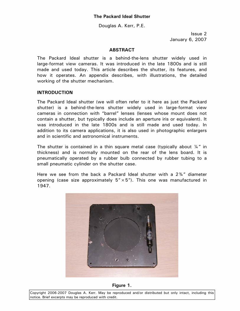
Here we see from the back a Packard Ideal shutter with a 2¾” diameter opening (case size approximately 5”×5”). This one was manufactured in 1947.
Figure 1.

The Packard Ideal Shutter Page 2
The design of the actual shutter mechanism allows the shutter to have a large clear opening in a relatively-small case size. The current manufacturer offers stock models with clear openings from 1½” in diameter (case size 3¼”×3¼”) up to 3½” in diameter (6½”×6½” case), and special order models with clear openings up to 8” in diameter (14”×14” case). The larger units are mostly used for scientific and astronomical applications.
THE SHUTTER
The shutter uses three thin blades (sometimes called “leaves”, or “wings”), most commonly made of a stiff black fiber material (reminiscent of that used in the dark slides of photographic film holders) about 0.020” thick. Starting with the shutter open, when it closes, two leaves, separately pivoted near the bottom of the case, each near the center, swing toward the center of the opening, eventually slightly overlapping. They do not quite cover the top corners of the opening. At the same time, a guillotine blade (think “cigar cutter”) moves straight down to close the remaining area.
If you look closely at figure 1, you can see the portions of the opening closed only by the guillotine blade (the circular segments at the upper right and left); the guillotine blade appears slightly lighter than the two swinging blades. (You can see the complete arrangement of the blades and their motion in figures 2 and 3 in Appendix A.)
It is this use of three, rather than only two, blades that allows the case dimensions to be so modest for any given clear opening size.
The guillotine blade is the one moved by the shutter actuating mechanism, and is thus sometimes called the “master blade”. It is linked to one of the swinging blades with a small rivet, and that blade is linked to the other swinging blade by another rivet. Thus motion of the master blade will open or close all three blades.
The guillotine blade is well suited to its role as master blade since it moves almost purely “in linear translation” (that is, along a straight path and without any substantial rotation). Thus, in the simpler shutter models, the piston of the pneumatic cylinder can be connected to the master blade without requiring an intervening “connecting rod”.
The shutter operation is relatively quiet, and the sound made is not “sharp”.
OPERATING MODES
Background
Traditional camera shutters typically offer one or more of these modes:
• Instantaneous (I)—When the actuator is pressed, the shutter opens, remains open for a certain time (often settable), and then closes. (In

The Packard Ideal Shutter Page 3
simple “box cameras”, this time is usually fixed, typically in the area of 1/25 second.)
• Bulb (B)—When the actuator is pressed, the shutter opens and remains open until the actuator is released. This mode is well suited to exposures in the range of one to several seconds.
• Time (T)—When the actuator is pressed the first time, the shutter opens. Releasing the actuator makes no change. When the actuator is pressed a second time, the shutter closes. This mode is well suited to exposures longer than a few seconds.
The Long Exposure mode
The Packard Ideal shutter in its basic form (as for example, the Packard no. 5 shutter) offers a different mode than any of these three, one that we will call the Long Exposure mode. This mode depends on the fact that in the Packard shutter, air pressure on the pneumatic cylinder opens the shutter and negative pressure (vacuum) is required to close it. If the pneumatic cylinder connection is “left open”, the shutter remains in its current state.
By proper manipulation of the actuating bulb, this can be exploited either as essentially the familiar Bulb mode or as a variant on the Time mode. An essential ingredient in this manipulation is that the tail end of the bulb has an open vent, which can be closed by the thumb as required.
To provide the traditional Bulb mode, the photographer closes the vent hole of the bulb with his thumb, squeezes the bulb, and then keeps the vent closed. The resulting pressure opens the shutter. At the end of the exposure, the photographer (with the bulb vent still closed) releases the bulb. The resulting vacuum closes the shutter.
In actual practice, this manipulation may not provide a sufficient “volume” of vacuum to close the shutter when the bulb is released. Thus a more subtle manipulation may be required.
Here, the photographer closes the bulb vent and squeezes the bulb until resistance is felt (when the cylinder has completed its travel and the shutter has opened). The vent is then quickly uncovered and the bulb squeezed even further (to prepare it to give a greater volume of vacuum when it is released). The vent is then closed and, at the end of the exposure time, the bulb is released. The shutter closes reliably.
An alternative ploy is for the photographer, before beginning the exposure, to slightly compress the bulb with the vent open. Then to begin the exposure, the vent is closed and the bulb squeezed the rest of the way. When the bulb is then fully released (with the vent still closed), the volume of vacuum created is greater than the volume of air expelled under pressure, assuring full retraction of the piston.
The Packard Ideal Shutter Page 4
For longer exposures (where one would, on other shutters, use the Time mode), to open the shutter the photographer closes the bulb vent, squeezes the bulb, opens the vent, and gently releases the bulb. Since the vent is open, no substantial vacuum is created by the release, and thus the shutter remains open. When the desired exposure time has elapsed, the photographer (with the bulb vent still open) squeezes the bulb, closes the vent, and releases the bulb. The resulting vacuum closes the shutter.
The operation of the mechanism in this mode is illustrated and described in detail in Appendix A.
The Instantaneous mode
The Packard no. 6 shutter offers the Long Exposure mode (with its two sub-modes, as described just above) and also an Instantaneous mode.
The change between the two modes is done with a plunger (usually called a “pin”) which projects to the front of the lens board and which can be depressed so as to enter a hole in the shutter case. With the pin pulled out, the operation of the shutter is in the Long Exposure mode. When the pin is pushed into the shutter, it changes the operation of the mechanism so that an instantaneous exposure is given: closing the bulb vent and squeezing the bulb makes the shutter open and then close.
The operation of the mechanism in this mode is illustrated and described in detail in Appendix A.
The duration of the exposure cannot be directly changed, and in fact is somewhat variable, depending on the vigor with which the bulb is squeezed (and to some extent on the size of the shutter). Typical exposure times are in the range 1/15-1/25 second.
When the bulb is released (with the vent still closed), the vacuum that is created resets the mechanism for the next operation. As with the Bulb sub-mode of the Long Exposure mode, the volume of vacuum created by the release of the bulb may be insufficient to complete the reset. Thus, one of the special manipulation ploys described above under the description of the Bulb sub-mode may have to be employed.
With the no. 6 shutter in the Instantaneous mode (control pin depressed), it is still possible, though proper manipulation of the bulb, to effect the Time mode in order to hold the shutter open for focusing.
To do so, the bulb is squeezed gently until resistance is felt. This occurs when the blades are fully open and the trip mechanism that will be responsible for then closing the blades has just contacted the control pin. (It takes a substantial force to actually trip that mechanism.) As a result, the shutter is essentially “stalled” in the open condition.

The Packard Ideal Shutter Page 5
To reclose the shutter after focusing, the bulb is squeezed with the vent open, the vent closed, and the bulb released (just as in the normal exercise of the Time mode).
SHUTTER VARIANTS
Two other models of the Packard Ideal shutter, no longer manufactured, are of interest.
The Packard no. 7 model is essentially like the basic no. 5 except that the blades are made of a deep red transparent plastic. This model is intended for use on photographic enlargers when working with black and white film. With the shutter closed but the enlarger lamp lit, light still passes through the blades, with only the longer red wavelengths present (to which the printing paper is not sensitive, so as to allow the use of a darkroom safelight). Thus the photographer can adjust the magnification and masking on the print paper, and then open the shutter to make the actual exposure with “white light”.
The Packard no. 8 model has two pneumatic cylinders. One always actuates the shutter in the Long Exposure mode, while the other always operates it in the Instantaneous mode. Typically, both cylinders are connected to rubber bulbs, usually of two different colors (often with color-coordinated hoses!) to allow them to be easily distinguished.
One object is that the photographer can use the Long Exposure mode (typically in the Time sub-mode) to open the shutter for focusing on the ground glass. Then the shutter is closed, the film holder inserted, the dark slide drawn, and the other bulb used to make the actual exposure on an Instantaneous basis. This is more convenient than having to change the position of the control pin in the middle of this scenario. (But note that, as discussed above, “Time” opening for focusing can be attained with a no. 6 shutter switched to the Instantaneous mode.)
SPECIAL FEATURES
Packard Ideal shutters can be provided by the manufacturer with an electrical solenoid actuator rather than the pneumatic actuator. Most commonly the basic mechanism is that of the no. 5. The solenoid has a return spring, and the shutter is open when the solenoid is energized and closed otherwise.
Packard Ideal shutters are available with a flash synchronization contact, which closes when the shutter is completely open, essentially providing X-sync. This is suitable for use with electronic flash, or even with flash lamps in the Bulb sub-mode (maybe even in the Instantaneous mode, given the relatively-long shutter open time there).
The Packard Ideal Shutter Page 6
INSTALLATION CONSIDERATIONS
Orientation of the shutter
The normal orientation of the Packard shutter is with the pneumatic cylinder vertical and its pneumatic connection at the bottom (as shown in figure 1). (This places the cylinder on the right side of the shutter as we would see the shutter looking at it from behind the lens board.) This is the most desirable orientation, since then the blade system is bi-stable. That is, the working of gravity on the swinging blades makes the blades, when open, have a small force keeping them open, and, when closed, have a small force keeping them closed.
With the shutter oriented with the pneumatic cylinder horizontal, the stability of the system is neutral, and thus there is no gravitational force keeping the blades in the open or closed position. Of course, friction will do the job in most cases, but there is always the risk that vibration of the camera between shots could slightly open the shutter. Many authorities recommend that, in any event, the shutter should be “sucked closed” before removing the dark slide from the film holder. Of course, usually the shutter would have recently been opened to allow focusing on the ground glass and then closed, thus automatically taking care of that.
With the shutter in inverted orientation (cylinder vertical pneumatic connection at the top), there is actually a gravitational force that will tend to open the blades when they are closed, and close them when they are open. Thus, mounting in that orientation should be avoided.
Basic mounting
The basic installation of the Packard Ideal shutter is directly to the rear of the lens board. The lens is normally supplied with a thin black felt piece glued to its front side. This provides a resilient mounting for the lens while maintaining a light seal.
If the lens has a projection to the rear of the board, a spacer block of adequate thickness to embrace the projection, with a hole of suitable diameter, must be interposed between the board and the shutter. The interior of the hole should be painted flat black to minimize light scatter.
The shutter is mounted with four screws through holes in the corners. Care should be taken not to tighten the screws so much as to distort the case. It is actually advantageous to leave one of the screws a little loose in case the rear of the lens board isn’t perfectly planar. (Some users only apply three screws.)

The Packard Ideal Shutter Page 7
Airway routing
The connection to the pneumatic cylinder must somehow be brought through the plane of the lens board to allow connection of the tubing leading to the rubber bulb. The manufacturer can provide threaded nipples with a short “hose barb” on each end for this purpose. Normally, the nipple passes through the lens board adjacent to the shutter, and is retained by nuts with washers. The inner end of the nipple is connected to the pneumatic cylinder with a short length of tubing.
If the shutter used has a case size nearly that of the lens board, there is no real estate available on the board for this nipple. In such cases, a hole may be drilled through the shutter case itself, and a long nipple run through the case and then the board.
The only area in the shutter that is clear of the entire mechanism and thus suited for this purpose is in the upper left corner (as seen from the rear with the shutter mounted in its normal orientation—the upper right corner as seen in the figures in Appendix A). The hole must usually overlap the hole already provided for a mounting screw at this location.
To locate such a hole, the shutter case cover should be removed (take out all screws visible from the rear) and the outline of the adjacent portion of the master blade, with the shutter fully opened, should be traced on the inside of the case to show the limit of the clear area. The entire blade assembly (with lever, for a no. 6 shutter) should then be removed, intact, before drilling the hole on the case proper. Be sure to note how the three leaves overlap so this situation can be reconstituted at reassembly.
Then the shutter case cover should be put temporarily back in place and a matching hole drilled through the cover, using the hole already drilled in the case proper as a jig.
Both holes should be deburred and all the residue carefully removed from the case and cover before replacing the blade assembly.
The airway nipple serves as one of the mounting screws. As always, care should be taken not to tighten the nuts so much that there is risk of deforming the case. The mounting screw opposite the nipple should perhaps be left a little loose (or even omitted). If the thickness of the spacer block (when used) is sufficient, it is attractive to actually place a thin nut on the nipple just on the back face of the board, and tightened substantially to actually retain the nipple in the board. Then another nut can be placed behind the shutter case, tightened cautiously to aid in the retention of the shutter.

The Packard Ideal Shutter Page 8
The control pin
A Packard Ideal no. 6 shutter should be provided with an Instantaneous mode control pin assembly. This includes a small flange to be mounted to the front face of the lens board with screws.
It can be tricky to locate the proper position for the hole in the lens board through which the control pin assembly must pass. The hole can be larger in diameter than the pin proper. The flange will cover any excess clearance. The pin should be depressed so it fully enters the shutter before screws for the flange are applied.
One approach to locating the hole is to insert a length cut from the tip of a nail of proper diameter into the hole of the shutter that admits the pin (with the point outward). The length should be such that the far end seats in the receiver on the shutter case cover, leaving only a small projection at the pointed end. Be sure to deburr the cut end of the piece and remove any “filings” before inserting it into the shutter.
The shutter can then be put in place and the tip of the nail will mark the proper location of the hole on the rear face of the lens board.
Note that in some cases of a large diameter barrel lens, the diameter of the mounting flange may be so great as to interfere with the placement of the control pin. If the use of the Instantaneous mode is important, a semicircular notch may often be filed into the lens flange to clear the pin and its flange.
Use with multiple lenses
Photographers having a number of barrel lenses may wish to use one Packard Ideal shutter in common for all of them. One approach is to mount these lenses in lens boards smaller than the native board size for the camera. The camera is then fitted with a lens board adapter that receives these smaller boards. The shutter is mounted to the rear of the adapter. Details of this work are beyond the scope of this article
MAINTENANCE
The Packard Ideal shutter does not require any routine maintenance, and it has no adjustments. No lubrication of any part of the mechanism is required, and no lubricant (not even powdered graphite) should be applied anywhere (including to the pneumatic cylinder).
Sometimes rust will form on the inner surface of the shutter case over time (most of the shutters have steel cases). In this event, the case cover should be removed (take out all screws visible from the rear) and the entire blade assembly (with lever, for a no. 6 shutter) should be removed intact. The rust should then be removed from both halves of the case with no. 400 abrasive paper or fine steel wool. Any rust on the shutter blades should be removed
The Packard Ideal Shutter Page 9
by wiping with a slightly damp paper towel. Be very careful to remove all residue before reassembly.
HISTORY OF MANUFACTURE
It is reported that the Packard shutter design was introduced by Culmer Packard, but we have little information beyond that. Some authorities indicate that the design was introduced in about 1890, but others report that initial forms of the shutter were introduced as early as 1865. There have been few design changes for many decades.
For many years, the Packard Ideal shutter was manufactured by Michigan Photo Shutter Co. of Kalamazoo, Michigan. In about 1973, the business was bought by Professional Photographic Products of Hammonton, New Jersey (Reno A. Farinelli and John W. Mazzeo, owners). They later changed the name of the firm to Packard Ideal Shutter Co.
In 2005, Reno Farinelli (the son of Reno A. Farinelli) acquired the business and moved it to Fiddletown, California (northeast of Sacramento), where it operates today as the Packard Shutter Company.
#
The Packard Ideal Shutter Page 10
APPENDIX A
Operation of the Packard Ideal shutter
In this Appendix, we will describe (with illustrations) the operation of the Packard Ideal shutter. This illustrations will be of a Packard Ideal shutter with a 2¾” opening (case size approximately 5”×5”).
The shutter will be portrayed rotated 90° clockwise from its standard orientation—the bottom of the shutter will be to our left. All mention of directions (up, down, etc.) here will be as seen in the illustrations.
Long Exposure mode
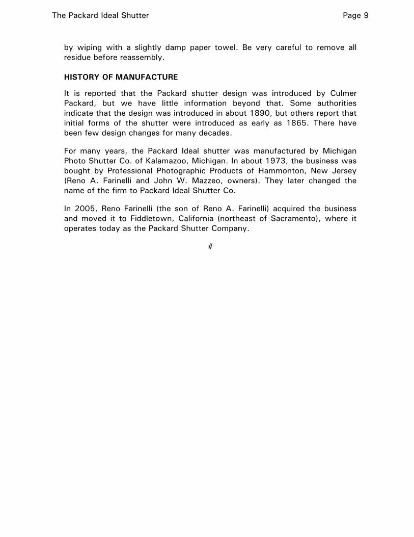
In figure 2 we see the shutter with the rear of the case removed and the shutter in its closed condition. The pin that causes the shutter to adopt the Instantaneous mode is not in place, as we will be seeing the Long Exposure mode at work.
Figure 2.
We have included the piston (removed from the cylinder) in the mechanism as photographed to illustrate how it is connected.
In a no. 6 shutter, the piston connects to the master blade through a link. The link bears a long pin (piston pin) passing through the end of the piston. A latch pin at the right end of the link engages a notch in the master blade. That pin also connects to the lower end of a lever. The lever is held upwards by a spring, ensuring that the latch pin engages the notch in the master blade. (The lever is involved in the operation of the Instantaneous mode, as we will see in the next section.)
The Packard Ideal Shutter Page 11
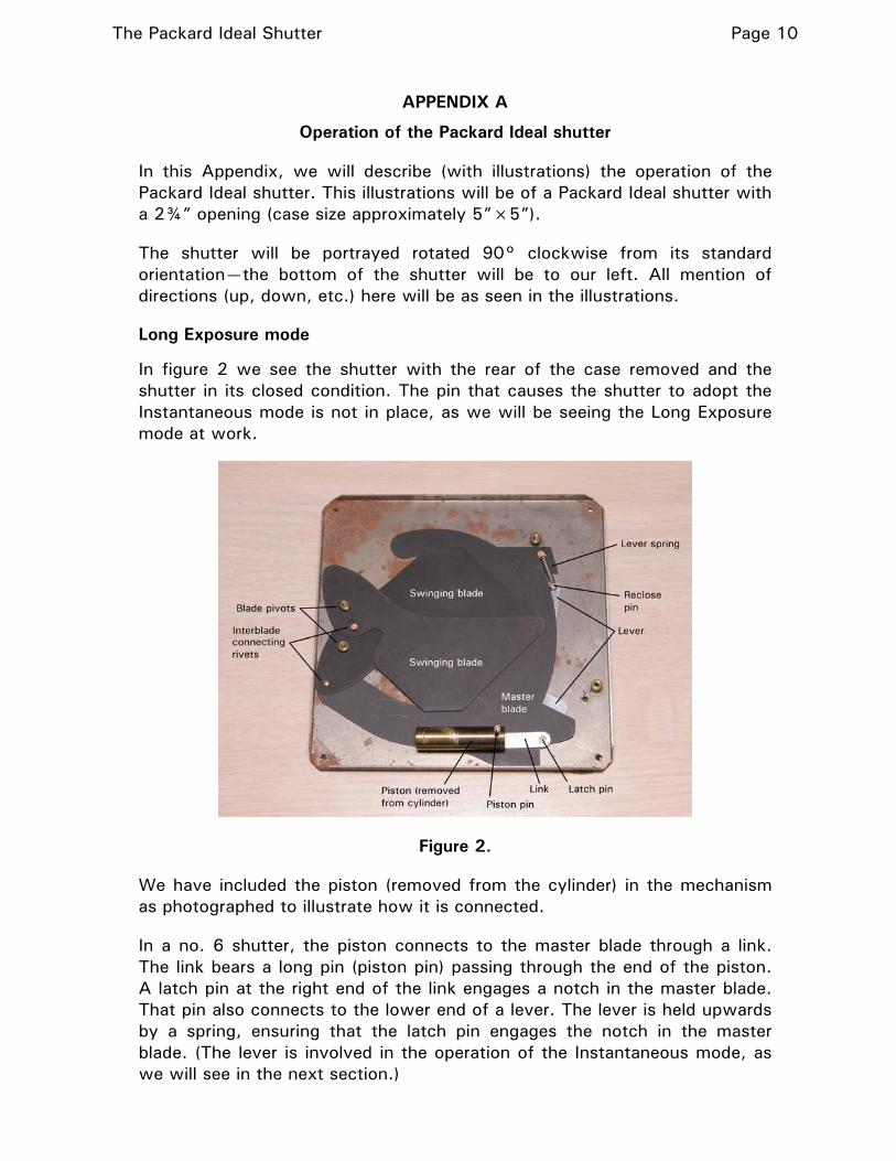
In figure 3 we see the shutter partway through its opening stroke. You can easily see the arrangement and movement of the three blades.
Figure 3.
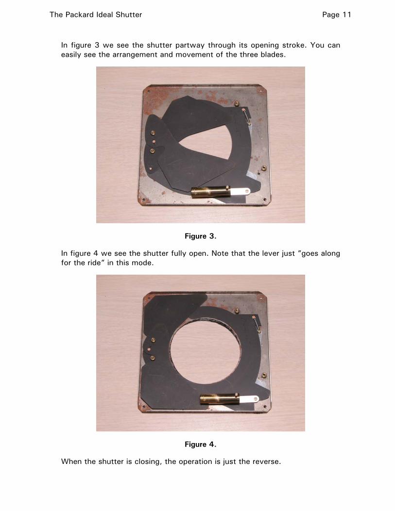
In figure 4 we see the shutter fully open. Note that the lever just ”goes along for the ride” in this mode.
Figure 4.
When the shutter is closing, the operation is just the reverse.
The Packard Ideal Shutter Page 12
Note that in a no. 5 shutter (which has only the Long Exposure mode), there is no lever nor link, and the piston pin is staked directly to the master blade.
Instantaneous mode
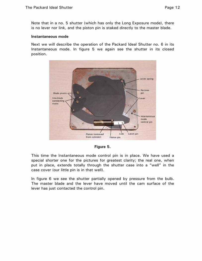
Next we will describe the operation of the Packard Ideal Shutter no. 6 in its Instantaneous mode. In figure 5 we again see the shutter in its closed position.
Figure 5.
This time the Instantaneous mode control pin is in place. We have used a special shorter one for the pictures for greatest clarity; the real one, when put in place, extends totally through the shutter case into a “well” in the case cover (our little pin is in that well).
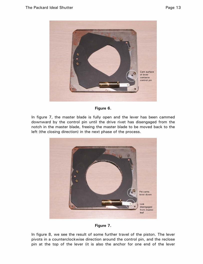
In figure 6 we see the shutter partially opened by pressure from the bulb. The master blade and the lever have moved until the cam surface of the lever has just contacted the control pin.
The Packard Ideal Shutter Page 13
Figure 6.
In figure 7, the master blade is fully open and the lever has been cammed downward by the control pin until the drive rivet has disengaged from the notch in the master blade, freeing the master blade to be moved back to the left (the closing direction) in the next phase of the process.
Figure 7.
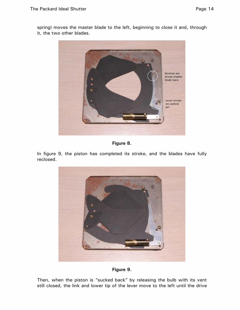
In figure 8, we see the result of some further travel of the piston. The lever pivots in a counterclockwise direction around the control pin, and the reclose pin at the top of the lever (it is also the anchor for one end of the lever
The Packard Ideal Shutter Page 14
spring) moves the master blade to the left, beginning to close it and, through it, the two other blades.
Figure 8.
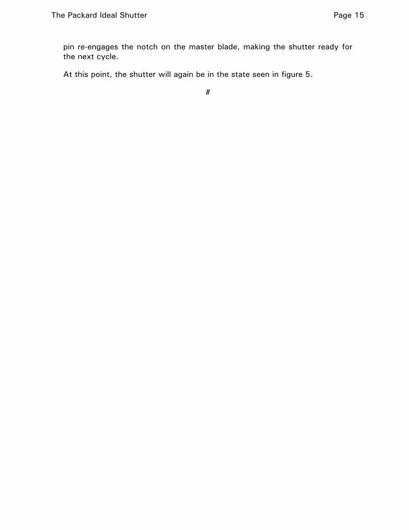
In figure 9, the piston has completed its stroke, and the blades have fully reclosed.
Figure 9.
Then, when the piston is “sucked back” by releasing the bulb with its vent still closed, the link and lower tip of the lever move to the left until the drive
The Packard Ideal Shutter Page 15
pin re-engages the notch on the master blade, making the shutter ready for the next cycle.
At this point, the shutter will again be in the state seen in figure 5.
#