Embed Size (px)
Citation preview
Center for Computational Mechanics
Washington UniversitySt. Louis, Missouri 63130
Report WU/CCM-93/4
THE p-VERSION OF THE FINITE ELEMENT METHOD
IN INCREMENTAL ELASTO-PLASTIC ANALYSIS
Stefan M. Holzer
Post-Doctoral Fellow
Zohar Yosibash
Graduate Research Assistant
December 1993
https://ntrs.nasa.gov/search.jsp?R=19940015563 2018-05-26T08:57:44+00:00Z
TABLE OF CONTENTS
Abstract ............................ ii
Acknowledgement ........................ ii
Introduction ............................ 1
Finite element approximation .................... 3
Numerical aspects of J2 plasticity ................... 6
Implementation .......................... 8
The thick-walled tube under internal pressure ............. 9Analitica/solution ........................ 9
Numerical examples ...................... 11
Practical Application: The cold working of an attachment lug ..... 23
Summary and conclusions ..................... 27
References ............................ 28
-i-
ABSTRACT
Whereas the higher-order versions of the finite element method (the 1>-andhp-versions) are fairly well establishedas highly efficient methods for monitoringand controlling the discretization error in linear problems, little has been done toexploit their benefits in elasto-plastic structural analysis. In this paper, we discusswhich aspects of incremental elasto-plastic finite element analysis are particularamenable to improvements by the p-version. These theoretical considerationsare supported by several numerical experiments. First, we study an example forwhich an analytical solution is available. It is demonstrated that the p-versionperforms very well even in cycles of elasto-plastic loading and unloading, notonly as compared to the traditional h-version but also in respect to the exactsolution. Finally, an example of considerable practical importance - the analysisof a cold-worked lug - is presented which demonstrates how the modelling toolsoffered by higher-order finite element techniques can contribute to an improved
approximation of practical problems.
ACKNOWLEDGEMENT
The research work of the first author has been supported by the German Re-
search Foundation DFG under grant Ho1517/1-1. This support is gratefully ac-knowledged. Both authors acknowledge partial support by the Lyndon B. JohnsonSpace Center of the National Aeronautics and Space Administration under GrantNAG 9-622. The research work of the second author has been supported in part
by the Air Force Office of Scientific Research under Grant F49620-93-1-0173.The authors would like to thank Professor B. A. Szab5 for the suggestion to
write this paper and for many interesting remarks and discussions. Furthermore,we would like to thank Mr. S. Prost-Domasky for his assistance with using the
ADINA code.
KEY WORDS
Plasticity, incremental theory, numerical analysis, finite element method, error
estimation, cold-work.
-ii-
1. Introduction
Elasto-plastic analysis is of increasing importance in all fields of engineering
sciences. However, real-life elasto-plastic problems are difficult to solve because they are
non-linear in nature. Approximate numerical methods are required for solving practical
problems of elasto-plasticity. The last two decades have witnessed a great deal of research
for finding approximate solutions to elasto-plastic problems by the finite element method
(FEM). For an excellent review of the techniques of elasto-plastic modeling in the
framework of the finite element method, we refer to [1].
Almost all research work on elasto-plastic finite element analysis was based on the
traditional h-version of the finite element method. The theoretical basis of the h-version is
explained in [2]; see, e.g., [3] for details on the application of the h-version to elasto-
plasticity. Whereas a lot of attention has been focussed on realistic material models, the
equally important issue of the accuracy of numerical modeling, including questions of
discretization errors and convergence of the error in energy norm, remain largelyunaddressed (see, however, [4], [5]).
During the last decade, techniques for monitoring the discretization error in finite
element approximations have been studied thoroughly, and new strategies for an efficient
minimization of the error in energy norm have been developed. In the p-version of the
FEM, the polynomial degree of the finite element approximation is increased to improve
the accuracy of the solution, rather than following the traditional approach of mesh
refinement (h-version). The hp-version combines mesh refinement and increasingpolynomial degrees.
The theoretical basis and convergence properties of the h-, p-, and hp-versions of the
FEM for linear elliptic problems have been well established. For a survey of the state-of-
the-art of the p- and hp-versions of the finite element method based on the displacement
formulation, the reader is referred to [6]. By all measures of performance, the higher-
order methods provide superior accuracy (with respect to the discretization error) than
their h-version counterpart for a large class of linear problems including linear elasticity.
The performance of the p-version for elasto-plastic stress analysis problems has not
been investigated until very recently. To the authors' knowledge, the first numerical
experiments which include incremental elasto-plastic material models in the frame of
higher-order finite element methods have been reported in [7]. However, at that time no
further discussion or evaluation of the efficiency of the p-version for this class of
problems has been given. The first author of the present study has developed an
experimental finite element code named FEASIBLE (cf. [7]) which includes p-version
capabilities and provides elasto-plastic material laws as well as multi-stage analysis. This
implementation has been employed for the numerical examples included in sections 5and 6.
-- 2
Recently, the applicabilityof thep-versionfor solvingelasto-plasticproblems,usingthedeformation theory of plasticity, has been investigated numerically in [8]. This study
shows that, even though the deformation theory is, strictly speaking, restricted to cases
where the principal stresses remain proportional to each other throughout the plastic.
process, both theories yield very similar results in many cases. However, the problem
categories amenable to the deformation theory do not include unloading and cyclic elasto-
plastic processes.
Therefore, the present paper focusses on the incremental theory of plasticity (for an
introduction, see, e.g., [1], [9]). The paper is organized as follows: We identify those sub-
tasks of the elasto-plastic finite element procedure which determine the computational
performance and accuracy of the numerical analysis. Subsequently, we discuss in which
steps of the elasto-plastic analysis we would expect improvements when switching to the
p-version. It is shown that many of the advantages of the p-version in purely linear
analysis carry over to elasto-plastic problems. A numerical study of the loading and
unloading of a thick-walled cylinder under internal pressure is presented. For this
problem, an exact solution is available. The analytical results are then compared with the
finite element solutions obtained by the p-version and the h-version. We demonstrate that
the p-version method performs very well, also as compared with the h-version.
Finally, some unique features of the p-version finite element code are illustrated
which permit realistic modeling of practical engineering problems. The finite element
solution to a lug which undergoes cold-work expansion is provided and compared with
the approximate closed-form solution often used in practice by engineers. This example
demonstrates that many cold-working problems demand a finite element analysis when
other than very crude accuracy requirements are imposed. Furthermore, it shows that the
p-version of the FEM makes the analysis of such problems very convenient and easy aswell as reliable and robust.
-- 3
2. Finite element approximation
Once a specific material model has been selected and the geometrical and mechanical
idealization of the structure has been determined, the problem of structural analysis is cast
in the form of a purely mathematical problem_ The finite element method is a tool for
solving this well-defined mathematical problem approximately. The primary aim of the
finite element analysis is to find as good an approximation to the exact solution of the
mathematical problem as can be obtained with a given amount of engineering work and
computer resources. The issue of how well the selected mathematical model corresponds
to the physical reality is to be treated completely independently of the issue of the
numerical accuracy of the finite element solution. In the present paper, we focus
exclusively on the errors introduced by the finite element discretization, not on the
physical modeling issue.
The finite element method based on the displacement formulation starts by
minimizing the functional of the potential energy
I-I(_) = ½ B(_,_)- F(_) (1)
over a finite-dimensional subset ,_ of the space /_(_) of functions which have finite
swain energy over the domain f_ and fulfill the displacement boundary conditions. Here,
the bi-linear form ½ B(_, _) denotes the strain energy corresponding to some displacement
field a and F(_) the work of the applied loads. Thus, an approximation uv_ _ _(f2),
minimizing I-[(a) over _f2), is obtained, whereas the exact solution uex minimizes l-I(a)
over g(f2).
Consequently, for an assessment of the efficiency of a specific finite element scheme,
the magnitude of the discretization error in the energy norm is monitored as a function of
the number of degrees of freedom N used in the finite element approximation are. The
error in energy norm is defined by
def / "
I1 11 - qn( e - (2)
In the present study, the p-version of the FEM is applied in the form of a uniform p-
extension, increasing the polynomial degree of the approximation uniformly on the entire
mesh. As far as linear analysis is concerned, the p-version is distinctly superior to the h-
version for problems which have an exact solution that is analytic throughout the domain.
In such cases, exponential convergence rates (i.e., II ll can be achieved
asymptotically (N---_oo) with simple finite element meshes, whereas the best
convergence rate of the h-version is only algebraic (i.e., [[glle = cN 4 ).
-- 4
Even for problems which include a finite number of points where singularities occur
in the stresses, the p-version converges (algebraically) at least twice as fast as the h-
version. Resorting to the hp-extension, the exponential convergence rate can be recovered
even for these singular problems. Convergence rates significantly better than algebraic
can be obtained in the pre-asymptotic range (i.e., for practical N) by performing the p-
extension on a geometrically graded mesh in these cases, cf. [6].
In elasto-plastic analysis, FI(_) is a non-linear function of _ so that the properties of
the FEM for linear analysis do not carry over to elasto-plasticity directly. However, in the
incremental theory of plasticity, we solve a sequence of linearized problems with the
same geometry, but strain-dependent material properties and loads. The final solution is
obtained as the sum of those of the quasi-linear steps. Therefore, the overall performance
of the non-linear analysis will be determined by the smoothness of the exact solutions of
the stepwise problems.
The smoothness properties of the exact solution of purely elastic problems are well
known and can generally be determined a priori from the geometric shape and the
boundary conditions; on the other hand, little has been done yet to inquire how much the
introduction of elasto-plastic material behavior changes the smoothness properties of the
corresponding purely elastic solution.
However, when deciding which finite element method is more appropriate when
solving an elasto-plastic problem, the question of smoothness is of little relevance
because the higher-order methods perform significantly better for problems in any of the
two categories of smoothness discussed above. This important fact is often overlooked.
Furthermore, it is worth noting that the elastic-plastic material is still characterized by
continuous strains so that elasto-plasticity does not introduce any kind of an abrupt
"material interface" inside the elements. Such a situation might cause the p-version to
yield oscillatory answers. However, it does not occur in small-strain elasto-plasticity since
there is always a continuous change in the material properties, even though the one-
dimensional ideal elasto-plastic stress-strain relationship intuitively suggests some kind
of "discontinuity". Even upon unloading and reloading, the strains and consequently the
material properties (directly depending on the strains) remain continuous.
All contained plastic flow problems fall into the category of completely continuous
strains and, consequently, the corresponding displacements can be expected to be at least
not much more unsmooth than those resulting from purely elastic problems.
As far as uncontained plastic flow is concerned, the underlying mathematical problem
changes from the elliptic to the hyperbolic type, including possible bifurcations,
multiplicity of the solution, and the like; such problems are strictly beyond the limits of
small-strain elasto-plastic analysis for both the h- and p-versions of the FEM. They
cannot be solved by methods based on the principle of minimum potential energy. Of
5
course,the physicalproblemfinally emergesinto unrestrictedplasticflow. However, theFEM does not directly model the physical problem, but is only a tool for solving amathematical problem. If unrestrictedplastic flow is to be analyzed, a differentmathematicalmodel .has to be used, not just a different type of finite elementapproximation.
The accuracy of the strains computed from the finite element solution is even more
important in elasto-plastic analysis than in purely linear problems because the stress-
strain law itself depends on the strains. We can expect accurate results only if the input to
the constitutive law is sufficiently accurate. Furthermore, errors tend to accumulate in a
prolonged incremental computation with many load steps.
A recent study [ 10] investigates numerically the pointwise quality of strains computeddirectly from the finite element approximation of the displacement field for linear
poblems. This is exactly the technique that will be employed in an elasto-plastic
computation to determine the current material properties. The numerical investigation
[10] identifies various patterns of convergence and shows that in all cases and for a wide
variety of stress concentration factors (a smoothness criterion) the p-version outperforms
the h-version. Furthermore, it is evident that very small errors in the energy norm are
usually required to achieve sufficient accuracy of the pointwise strains, even for quite
smooth solutions. Such global accuracy levels are impractical for an h-version approachdue to the slow convergence of this method.
In summary, all considerations indicate that the p-version of the FEM will be
beneficial for elasto-plastic computations, and there is no indication that the p-version
might give rise to any new numerical problems not encountered in the h-version. Ournumerical examples strongly support this.
6
3. Numerical aspects of J2 plasticity
In the present paper, we are dealing with the application of the p-version of the FEM
to problems from metal plasticity. The computations are based on the ideal elastic-plastic
J2 flow theory, using the von Mises yield law. Further assumptions include small
displacements and small strains. The incremental formulation of the von Mises yield lawstarts with the following assumptions:
The total strain increment can be decomposed into a purely elastic and a purely plasticpart:
dl_ = dlzel + dept (3)
We assume the engineering definition of the strain vector.
The yield criterion is independent of the hydrostatic pressure and of the third invariantof the deviatoric stress tensor:
2F = - %. (4)
J2 denotes the second invariant of the deviatoric stress tensor and (_y the uniaxial yield
stress of the material. No strain hardening is assumed. Only stress states such that F < 0
are permissible. Once the stress path reaches F = 0 in a point, plastic strains will develop
in that point upon further loading.
During a plastic loading increment, the stress state is confined to the yield surface
given by eq. (4):
In equation (5), d_ denotes the stress increment vector and the superscript t indicates
transpose.
The direction of the plastic flow is given by (normality rule)
= L- dJ (6)
Here, a_ is a proportionality factor and ¢r denotes the stresses in vectorial notation.
Using Hooke's law for the elastic part of the strains,
&el = D-lc/c, (7)
-- 7
whereD is the linear-elastic material matrix, formulas (3), (5), and (6) can be combined
to determine the elasto-plastic stress increment
OF _F tda = D.,& = D- -_F--F_F--1 / ' (8)
corresponding to a total strain increment de. Formula (8) defines the elasto-plastic
material matrix Dep. This relationship is needed in a finite element program to determine
the tangential stiffness matrix for a Newton-Raphson method or a similar scheme.
Furthermore, it can be used to integrate the constitutive.law on the integration point level
of the finite element method in case an explicit algorithm is to be used for that. Whereas
the correctness of the tangent stiffness matrix has only an influence on the efficiency of
the non-linear solver, the integration of the constitutive law has a direct impact on the
accuracy of the final results.
Much attention has been dedicated to the accurate integration of the constitutive law
during the last two decades (cf. [11], [12], [13], [14]). A comprehensive scheme of error
control and quality assurance in the FEM has to include this aspect, which is, however,
independent of the finite element discretization technique. With a view to practical
applications, and especially with respect to the complicated plastic laws which become
increasingly common in rock mechancis and concrete modeling, the authors of the
present study favor a fully general implicit scheme similar to the one presented in [14].
However, at present, only the traditional tangent-radial return method has been
implemented. This simple scheme can be considered sufficiently accurate for the von
Mises yield criterion without hardening provided that small steps are used for theintegration of the constitutive law.
However, the most challenging computational issue specifically related to the use of
J2 flow rules is created by the condition that the plastic strains correspond to an
incompressible mode of deformation (note that it follows form equations (4) and (6) that
the plastic strain increments have no volumetric component): Starting from a
compressible elastic behavior, the material becomes progressively more incompressible
during the elasto-plastic deformation process as the amount of plastic strain increases as
compared to the elastic strain. This will eventually lead to a severe locking problem in the
traditional h-version of the finite element method if the displacement formulation is used.
The problem of incompressibility locking in J2 plasticity has already been studied in [ 15],
and various schemes have been devised to avoid the locking, either by "reduced
integration" or by introducing an independent approximation of the hydrostatic pressure.
Today, most approaches use the mixed finite element method resulting from the latter
idea, entailing all the disadvantages and additional complications inherent to mixedmethods.
-- 8 °
On the other hand, the problem of locking due to incompressibility has been studied
extensively for the p-version of the finite element method (see [16], [17], [18]), and it has
been shown that no locking effects occur when the polynomial degree p is greater than 4.
No special precautions or mixed methods have to be introduced to obtain accurate results.
Our numerical experiments will demonstrate clearly that locking due to
incompressibility does not occur in the p-version analysis of the elastoplastic problem.
4. Implementation
In many details, the implementation of an elasto-plastic material law in a p-version
FEM code is identical to a standard h-version implementation. Therefore, we summarize
only briefly the main features of the implementation used for the present study:
First, we carry out a purely linear elastic analysis and perform a uniform p-extension,
starting at p=l (piecewise linear approximation). The maximum polynomial degree
available is p=8. The convergence of the strain energy is monitored. Based on the
assumption that the error in energy norm converges algebraically, a very reliable estimate
of the exact energy can be obtained by extrapolation from three different p-levels (cf. [6]).
Throughout the present study, the space of hierarchical tensor product trial functions has
been used (product space).
To avoid errors in the linear solution by approximate geometrical mapping, we always
use the blending-function method (see [6]) to describe curved boundaries accurately.
Therefore, we can use very large elements even in the presence of curved boundaries.
When the error estimate for the purely linear solution reaches a user-defined
threshold, the non-linear computation starts. There is no guarantee that the non-linear
solution will be of the same order of accuracy as the linear solution, but we rather expect
the nonlinear solution to be less accurate. We have already seen that, e.g.,
incompressibility effects which are not originally present in the system will be introduced
by the plastic material law, and those effects will slow down the convergence of the error
in energy norm. Therefore, it seems reasonable to impose very restrictive accuracy
requirements on the linear solution. In our practical computations, as a rule of thumb, we
set the desired accuracy of the linear solution to about 10% of what we would consider
reasonable for a purely elastic analysis.
The next step is to determine at which fraction of the total imposed load the system
will start to yield. The remaining load is divided into a number of load increments, and in
each of these, the Newton-Raphson method with a consistent tangent predictor is applied.
The Newton-Raphson iterations are stopped when both the relative magnitude of residual
force vector and of the change in the incremental displacements in either the Euclidean or
the maximum norm are smaller than a prescribed threshold. In each load increment, a
check for elastic unloading is performed in every integration point.
"9
Finally, stressresultsareavailableonly in the integrationpointssincetheincrementalelasto-plasticlaw hasbeenevaluatedonly there.To obtain stressresultselsewhere,aleast-squaresapproximationfor eachof the componentsof thestressvector is computedfor eachelementindividually. For this least-squaresfit, we employ the trial functionscorrespondingto the polynomial level usedin the finite elementapproximationof thedisplacements.
5. The thick-walled tube under internal pressure
First, we study an example for which an analytical solution is available, the thick-
walled tube under internal pressure. The analytical solution for both the loading and the
unloading - including elasto-plastic re-loading in the reverse direction - has been given in
[19]. It is one of the few elasto-plastic two-dimensional problems for which an analytical
solution even for the unloading is availabe, and therefore we use it as a basis for the
evaluation of the numerical quality of the h- and p-versions of the finite element method.
However, this problem is also of considerable practical interest since the pressurized
tube may be used as a model for the cold-working of holes, e.g., in aircraft engineering.
Rich et al. [20] suggest to use the analytical solution for the analysis of a wide range of
cold-worked holes, and in our practical application example, we will study how well this
solution is suited for a cold-worked lug.
Cold-working is a process which is used to produce favorable stresses that
significantly reduce the effects of stress concentration around a hole. In this method, an
oversized and tapered mandrel, sometimes with a lubricated sleeve, is pulled through the
hole to be cold-worked. Upon the removal of the mandrel, the hole is surrounded by a
region of residual compressive stresses. This method is generally used for holes at the
time of aircraft manufacture, as well as during service, to increase the fatigue life of
structural components.
5.1 Analytical solution
The analytical solution for the problem of the tube under internal pressure has been
given in [19] and applied to the cold-working process by [20]. The following assumptions
are adopted in the analysis:
• elastic-perfectly plastic material model
• plane strain situation
• von Mises yield condition
• incompressibility of both the elastic and plastic zones (no analytical exact solution
exists for compressible elastic deformation).
In the application to cold-working, the mandrel is assumed to remain purely elastic.
-- lO
Notation. Consider a tube with an intemal radius a and an extemal radius b, Young's
modulus Ep, Poisson ratio vp and uni-axial yield stress 6y. Denote the modulus of
elasticity for the mandrel by E b, its Poisson ratio by vb and its radius by a+I. The
difference I between the radii of the mandrel and the hole is called interference.
Upon inserting the mandrel into the tube, a plastic zone of radius p is created. This
radius is defined by the following implicit equation (if no solution exists for the equation,
the interference is simply too small to create a plastic zone):
+(9)
and the pressure between the mandrel and the hole can be shown to be
°2]P= (lY[21n-9 1-_-_qt'_[ a + •
(10)
2(Yy, b
ff P> -_- m_,
for us.
then the entire cylinder becomes plastic, and this case is of no interest
The circumferential stresses around the hole are given by:
[Go _ 21nr+l+= PO'y
air£p
p£r_b.
(11)
Upon removal of the mandrel, the tube undergoes an elastic unloading. If
2Gy [ a 2
are given by:
no reverse yielding occurs, and the residual circumferential stresses
-- 11
I_ 0 _---
21np+l+_-_ - 21nP-+a 1-_-Jr2(b2-a2)J
¢_Y {[ 02. a r2(b2-a2)J--_ -_.Pff-_]-[21nP+l--_2]a2(r2+b2)_
aSrSp
p_rSb.
(12)
Otherwise, compressive yielding occurs in the zone a < r < OR, where OR is given by the
implicit equation:
p_21n-_-a - 1+ _ - O.
PR 2Cy(13)
In this case, the circumferential stress is:
(Y0 =
p2oy{[21o +1+ ]2(L p
Jf£+£l_4_LL b2 r 2 ]
21n__r+1+ P_'l[04 b2JJ a<r<-Pn
Lb2+r jj p._<r p• 2 2p.+ .ll
2 _ 7jj p<r<b.
(14)
This problem is suitable for both the incremental and deformation theories of plasticity
because it is axisymmetric and the stresses are proportional.
Note that eq. (6) in [20] is not correct which renders the stresses in the compressive
plastic zone around the hole after unloading. The correct solution is found in [19].
5.2 Numerical Examples
The problem described in the previous section is solved by the p-version as well as
the h-version of the FEM. The finite element solutions to this problem will demonstrate
the capabilities of the p-version and its accuracy.
Comparison with the exact solution
We study a tube with an internal radius a=l.5in and an outer radius b=4.0in subjected
to a cold-working process. A plane strain situation is assumed. A pressure of P=62,000psi
-- 12
is applied to both the inner side of the tube and the outer face of the mandrel. We
determine the corresponding interference level as the sum of the radial displacements of
both bodies. Thus, an interference I--0.03399in is obtained. The material properties of the
tube are defined by Ep=10,000,000psi, the uniaxial yield stress gy=58,000psi, and
"Vp=0.49. We select this value of the Poisson ratio in order to be close to the exact
analytical solution which assumes elastically incompressible material. The displacement-
based finite element schemes cannot be applied if v--0.5 exactly. The mandrel's material
properties are taken to be Eb=30,000,000psi , and Vb=0.3. All finite element computations
are based on an elastic-perfectly plastic von Mises yield law.
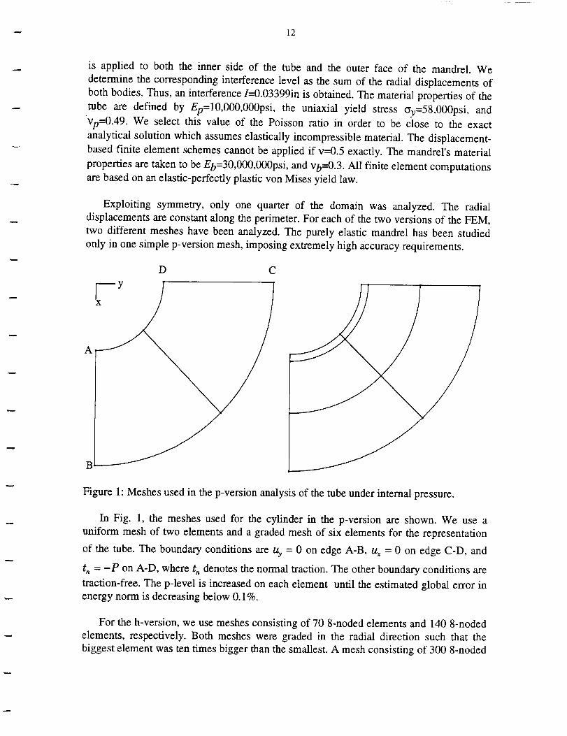
Exploiting symmetry, only one quarter of the domain was analyzed. The radial
displacements are constant along the perimeter. For each of the two versions of the FEM,
two different meshes have been analyzed. The purely elastic mandrel has been studied
only in one simple p-version mesh, imposing extremely high accuracy requirements.
D C
V y
Figure 1: Meshes used in the p-version analysis of the tube under internal pressure.
In Fig. 1, the meshes used for the cylinder in the p-version are shown. We use a
uniform mesh of two elements and a graded mesh of six elements for the representation
of the tube. The boundary conditions are Uy = 0 on edge A-B, us = 0 on edge C-D, and
tn = -P on A-D, where t,, denotes the normal traction. The other boundary conditions are
traction-free. The p-level is increased on each element until the estimated global error in
energy norm is decreasing below 0.1%.
For the h-version, we use meshes consisting of 70 8-noded elements and 140 8-noded
elements, respectively. Both meshes were graded in the radial direction such that the
biggest element was ten times bigger than the smallest. A mesh consisting of 300 8-noded
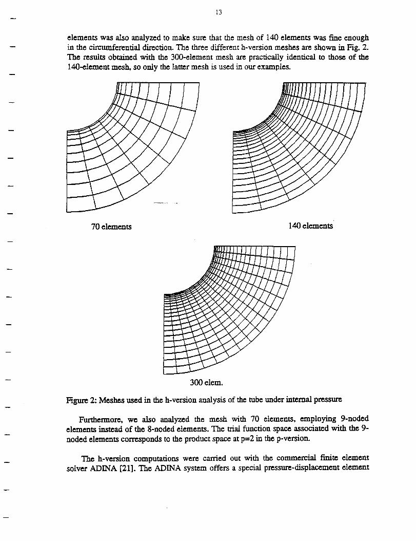
13
elements was also analyzed to make sure thatthe mesh of 140 elements was fineenough
in the circumferentialdirection.The threedifferenth-versionmeshes arc shown in Fig.2.
The resultsobtained with the 300-element mesh are practicallyidenticalto those of the
140-element mesh, so only the lattermcsh isused in our cxaml_les.
70 elements 140 elements
300 clcm.
1:;igur¢2: Meshes used in the h-versionanalysisof the tube under internalpressure
Furthermore, we also analyzed the mesh with 70 elements, employing 9-noded
elements insteadof the 8-noded elements. The trialfunctionspace associatedwith the 9-
noded elements corresponds to theproduct space atp=2 in the p-version.
The h-version computations were carried out with the commercial finiteelement
solver ADINA [21].The ADINA system offersa specialpressure-displacementelement
14
for incompressible materials, based on the mixed finite element formulation [22]. Tiffs
element was used in the analysis.
54000
44000
u)Q.
u_340O0
U)
¢-
•-- 24000E-n
(.1
14000 _ "--e p-Version 2 elements. [
EI---U p-Version 6 elements. IiZ=---AAnalytJcaJ sol.
4OOO1.5 2.0 2.5 3.0 3.5 4.0
Radial Distance from Hole Center. (in)
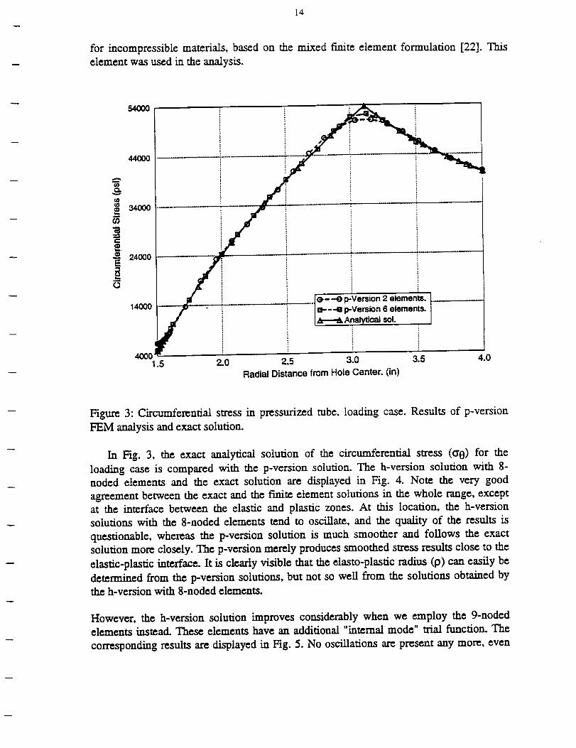
Figure 3: Circumferential stress in pressurized tube, loading case. Results of p-version
FEM analysis and exact solution.
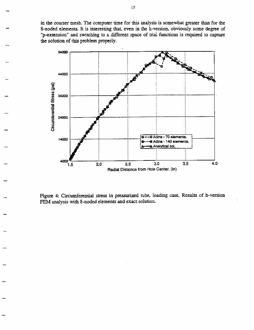
In Fig. 3, the exact analytical solution of the circumferential stress (c 0) for the
loading case is compared with the p-version solution. The h-version solution with 8-
noded elements and the exact solution are displayed in Fig. 4. Note the very good
agreement between tile exact and the finite element solutions in the whole range, except
at the interface between the elastic and plastic zones. At this location, the h-version
solutious with the 8-noded elements tend to oscillate, and the quality of the results is
questionable, whereas the p-version solution is much smoother and follows the exact
solution more closely. The p-version merely produces smoothed stress results close to the
elastic-plastic interface. It is clearly visible that the elasto-plastic radius (p) can easily be
determined from the p-version solutions, but not so well from the solutions obtained by
the h-version with 8-noded elements.
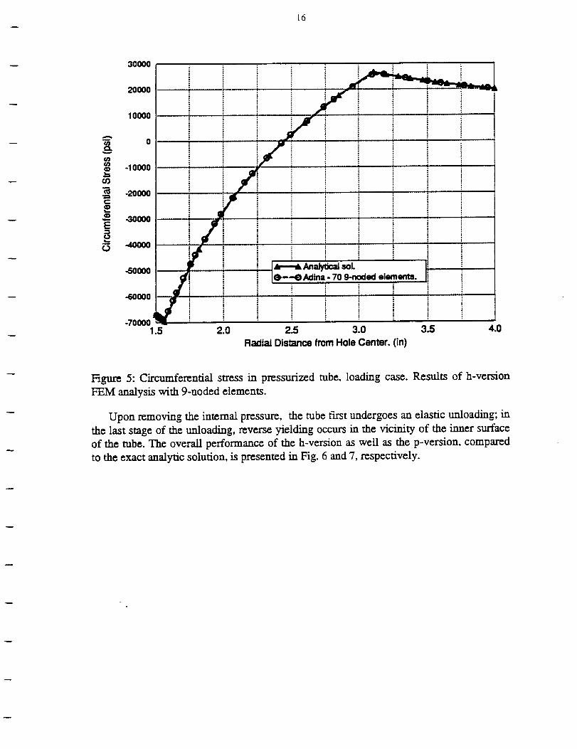
However, the h-version solution improves considerably when we employ the 9-noded
elements instead. These elements have an additional "internal mode" trial function. The
corresponding results arc displayed in Fig. 5. No oscillations are present any more, even
15
in the coarser mesh. The computer time for this analysis is somewhat greamr than for the
8-noded elements. It is interesting that, even in the h-version, obviously some degree of
"p-extension" and switching to a different space of trial functions is required to capture
the solution of this problem properly.
¢¢Je_
¢¢1tgl
w
¢/}
m
e-
$¢D
E
O
54oo0
44000
340O0
240o0
14000
4000
!
(>--e Adina- 70 elements.B---B Adina - 140 elements.
Analytical sol.
1.5 2.0 2.5 3.0 3.5
Radial Distance from Hole Center. (in)
4.0
Figure 4: Circumferential stress in pressurized tube, loading case. Results of h-version
FEM analysis with 8-noded elements and exact solution.
_6
3OOO0
!3
20OO0
1OOOO
-I 0000
-20000
-3OOO0
-4OOOO
-50OOO
-60000
-7OOOO1.5 2.0 2.5 3.0 3.5 4.0
Radial Distance from Hole Center. (in)
Hgure 5: Circumferential stress in pressurized tube, loading case. Results of h-version
FEM analysis with 9-noded elements.
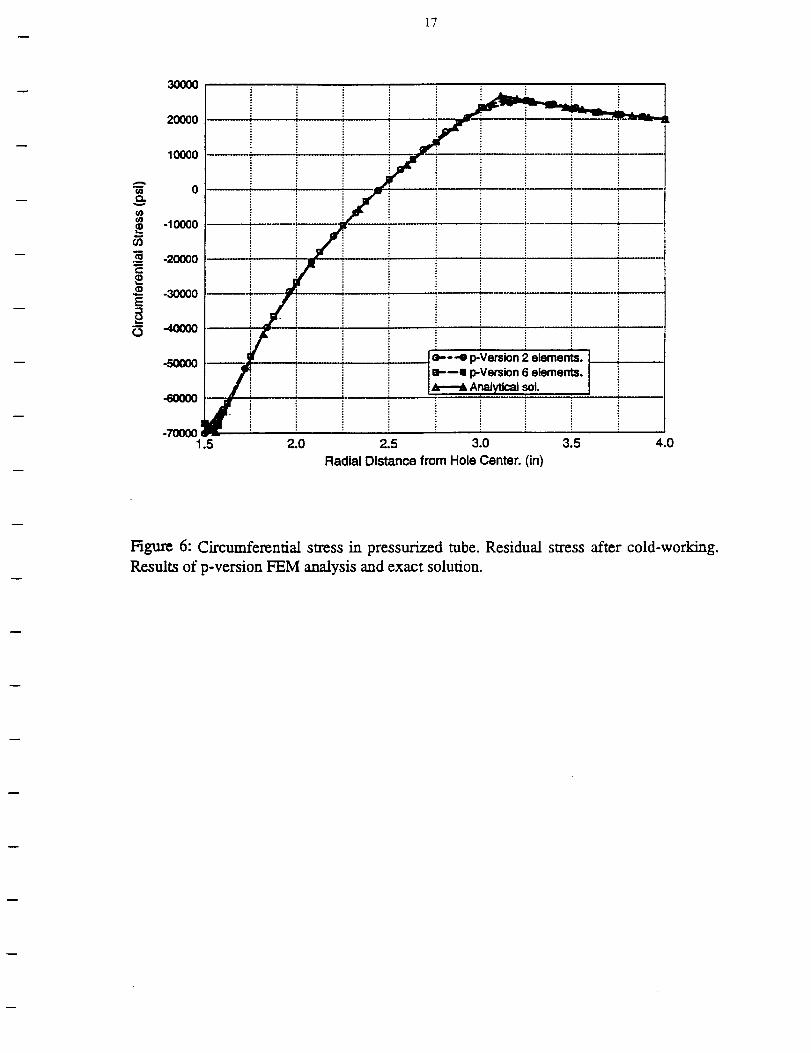
Upon removing the internal pressure, the tube first undergoes an elastic unloading; in
the last stage of the unloading, reverse yielding occurs in the vicinity of the inner surface
of the tube. The overall performance of the h-version as well as the p-version, compared
to the exact analytic solution, is presented in Fig. 6 and 7, respectively.
17
e_
g}
co
e.-
E-t
.o
3O(3OO
20000
10000
0
-10000
-20000
-30000
..4OO0O
-700001
iI
i i
i i _ ie--- 4 p-Version 2 elements.B.---m p-Version 6 elements.
Analytical sol.
1.5 2.0 2.5 3.0 3.5 4.0
Radial Distance from Hole Center. (in)
Hgure 6: Circumferential stress in pressurized tube. Residual stress after cold-working.
Results of p-version FEM analysis and exact solution.
18
3OOOO
2OO00
1oooo
A
•_ o
¢/3U3
-10oo0
-20000
-30000E
-40ooo
.5o0oo
-600oo
e---e Adina- 70 elements.m----e Adina- 140ele-ments.
An_yttcalsol.
-7OOOO1.5 2.0 2.5 3.0 3.5 4.0
Radial Distance from Hole Center. (in)
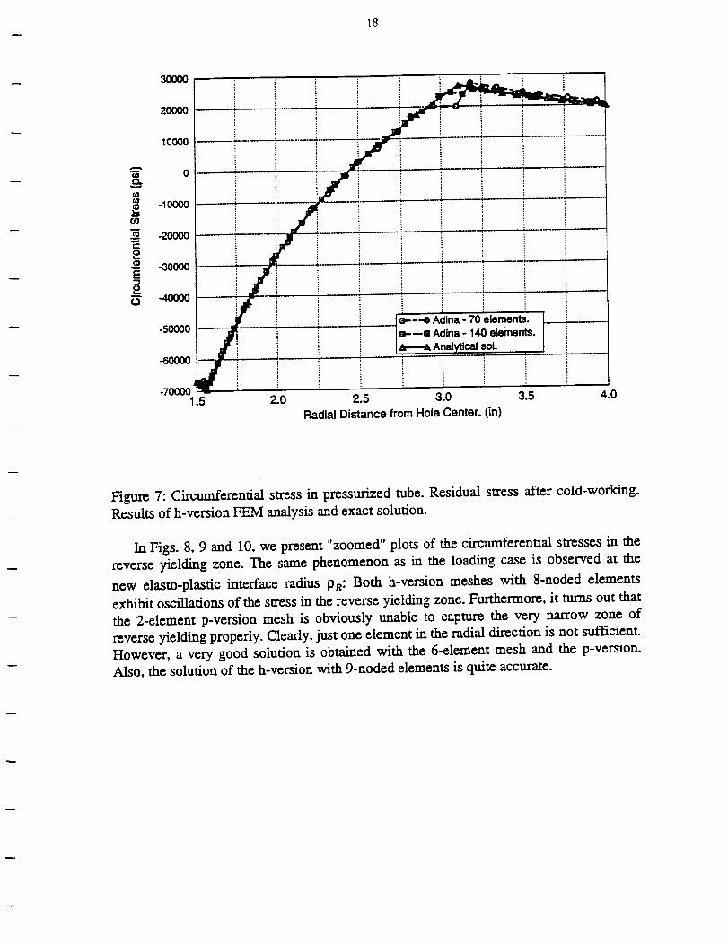
Figure 7: Circumferential stress in pressurized tube. Residual stress after cold-working.
Results of h-version FEM analysis and exact solution.
In Figs. 8, 9 and 10, we present "zoomed" plots of the circumferential stresses in the
reverse yielding zone. The same phenomenon as in the loading case is observed at the
new elasto-plastic interface radius PR: Both h-version meshes with 8-noded elements
exhibit oscillations of the stress in the reverse yielding zone. Furthermore, it turns out that
the 2-element p-version mesh is obviously unable to capture the very narrow zone of
reverse yielding properly. Clearly, just one element in the radial direction is not sufficient.
However, a very good solution is obtained with the 6-element mesh and the p-version.
Also, the solution of the h-version with 9-noded elements is quite accurate.
19
en
I
al
E
I
¢j
-5OO00
-60000
-70000
dIe,---.O p-Version 2 elements.I B'--= p-Version 6 elements.J_=----_ Analytical sol.
J
_,,'J i ,I
..'3"/"_,.f Jf /
. ..,=
° 2,."
1.5 1.6
Radial Distance from Hole Center. (in)
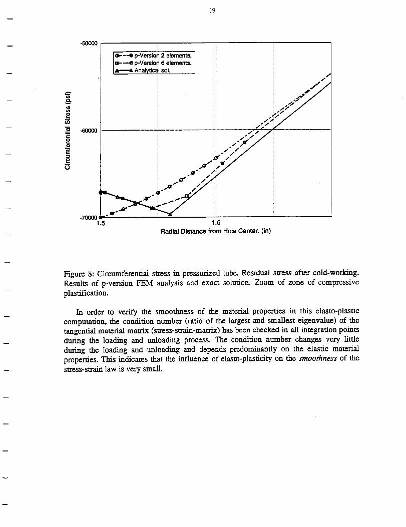
Figure 8: Circumferential stress in pressurized tube. Residual stress after cold-working.
Results of p-version FEM analysis and exact solution. Zoom of zone of compressive
plastification.
In order to verify the smoothness of the material properties in this elasto-plastic
computation, the condition number (ratio of the largest and smallest eigenvalue) of the
tangential material matrix (stress-strain-matrix) has been checked in all integration points
during the loading and unloading process. The condition number changes very little
during the loading and unloading and depends predominantly on the elastic material
properties. This indicates that the influence of elasto-plasticity on the smoothness of the
stress-strain law is very small.
20
to
tOto
(ON
e-
E
o
-50000
-6O00O
-700001.5
i
-.-e Adina- 70 elements.aa Adina- 140 elements.
Analyticalsol.
1.6
Radial Distance from Hole Center. (in)
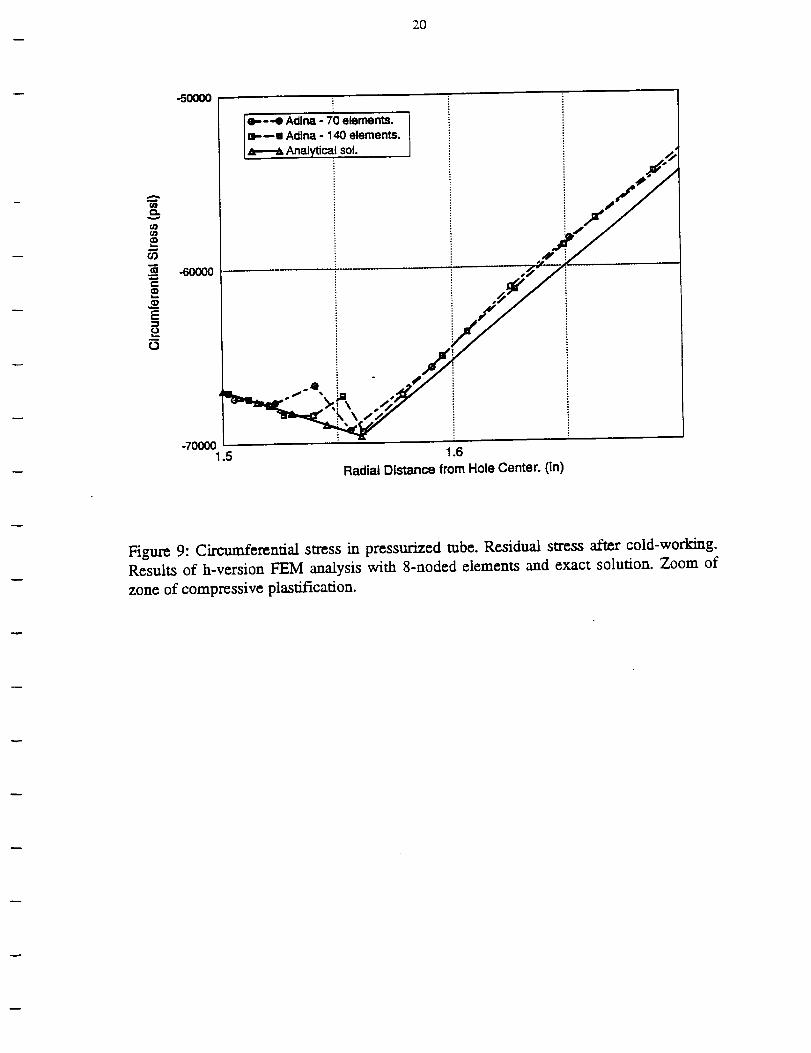
Figure 9: Circumferential stress in pressurized tube. Residual stress after cold-working.Results of h-version FEM analysis with 8-noded elements and exact solution. Zoom of
zone of compressive plastification.
2I
O1
O9
e-
E
+ i! ..,*' _
-7_eo i I ig
1.5 1.6
Racliai Distance from Hole Cemer. On)
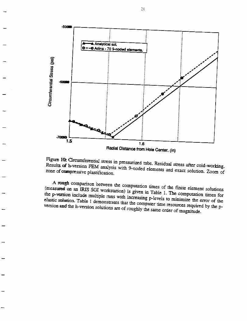
Hgurc 1(1: Circumferential stress in pressurized tube. Residual stress after cold-working.
Results of h-version FEM analysis with 9-noded elements and exact solution. Zoom ofzone of c(_mpressive plastification.
A rough comparison between the computation times of the finite element solutions
(measured on an IRIS SGI workstation) is given in Table 1. The computation times for
the p-version include multiple runs with increasing p-levels to minimize the error of the
elastic solution. Table 1 demonstrates that the computer time resources required by the p-version and the/a-version solutions are of roughly the same order of magnitude.
-- 22
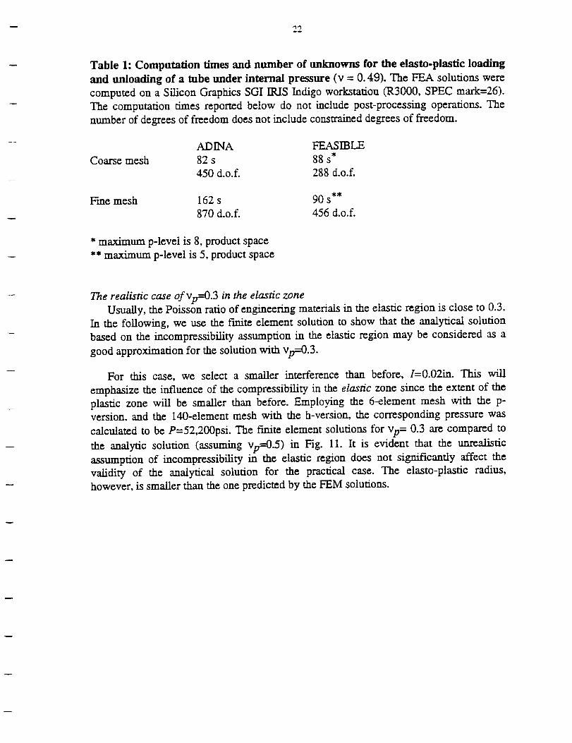
Table 1: Computation times and number of unknowns for the elasto-plastic loading
and unloading of a tube under internal pressure (v = 0.49). The PEA solutions were
computed on a Silicon Graphics SGI IRIS Indigo workstation (R3000, SPEC mark=26).
The computation umes reported below do not include post-processing operations. The
number of degrees of freedom does not include constrained degrees of freedom.
Coarse mesh
ADINA FEASIBLE
82 s 88 s
450 d.o.f. 288 d.o.f.
Fine mesh 162 s 90 s
870 d.o.f. 456 d.o.f.
* maximum p-level is 8, product space
** maximum p-level is 5, product space
The realistic case Of Vp-_.3 in the elastic zone
Usually, the Poisson ratio of engineering materials in the elastic region is close to 0.3.
In the following, we use the finite element solution to show that the analytical solution
based on the incompressibility assumption in the elastic region may be considered as a
good approximation for the solution with Vp=0.3.
For this case, we select a smaller interference than before, I=0.02in. This will
emphasize the influence of the compressibility in the elastic zone since the extent of the
plastic zone will be smaller than before. Employing the 6-element mesh with the p-
version, and the 140-element mesh with the h-version, the corresponding pressure was
calculated to be P=52,200psi. The finite element solutions for Vp= 0.3 are compared to
the analytic solution (assuming Vp=0.5) in Fig. 11. It is evident that the unrealistic
assumption of incompressibility in the elastic region does not significantly affect the
validity of the analytical solution for the practical case. The elasto-plastic radius,
however, is smaller than the one predicted by the FEM solutions.
23
20000
1O0O0
-10000
-20000
-30000m
(3-4OOOO
-5O0OO
ti
p-version6 elements.
-6OOO01.5 2.5 3.5
Radial Distance from Hole Center. (in)
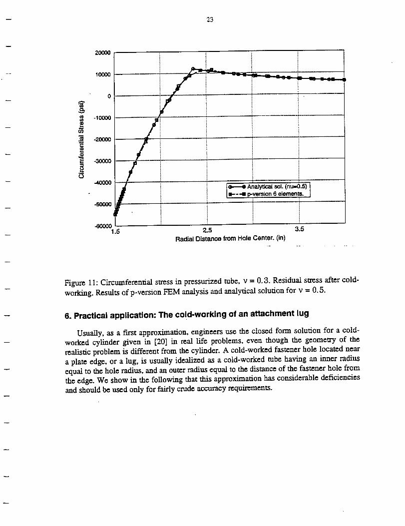
Figure 11: Circumferential stress in pressurized tube, v = 0.3. Residual stress after cold-
working. Results of p-version FEM analysis and analytical solution for v = 0.5.
6. Practical application: The co!d-working of an attachment lug
Usually, as a first approximation, engineers use the closed form solution for a cold-
worked cylinder given in [20] in real life problems, even though the geometry of the
realistic problem is different from the cylinder. A cold-worked fastener hole located near
a plate edge, or a lug, is usually idealized as a cold-worked tube having an inner radius
equal to the bole radius, and an outer radius equal to the distance of the fastener hole from
the edge. We show in the following that this approximation has considerable deficiencies
and should be used only for fairly crude accuracy requirements.
24
A
q
• • nun all
_ 0 -_",;" _,"
B C D
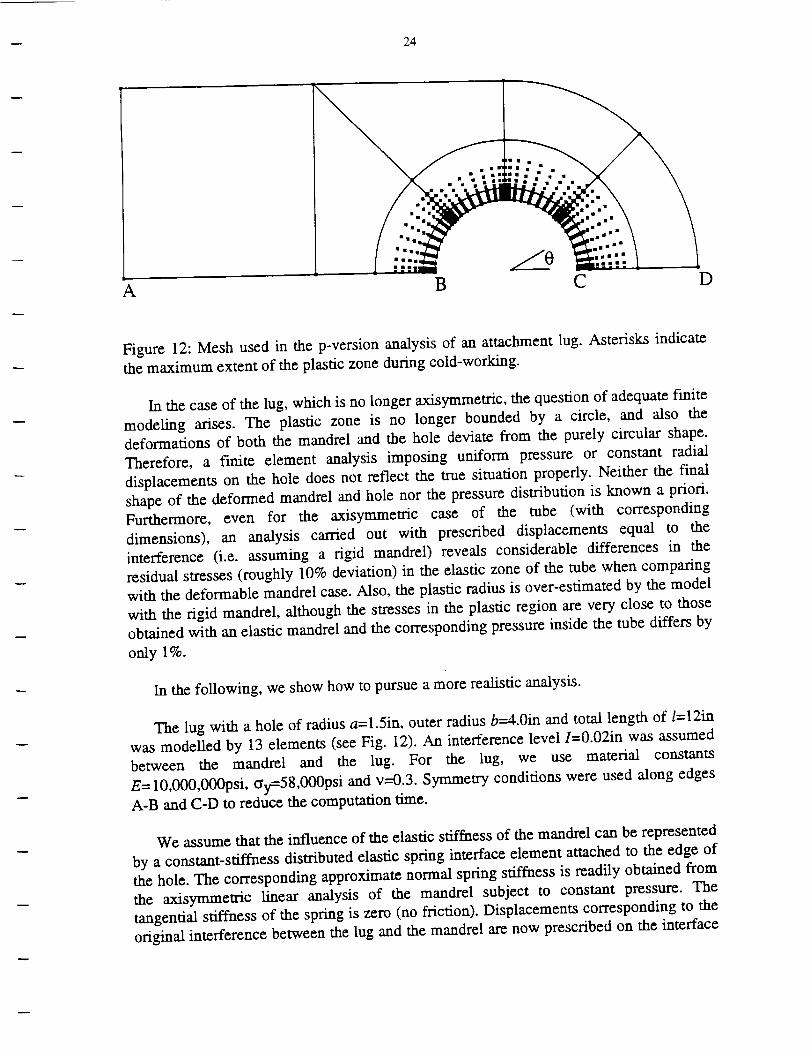
Figure 12: Mesh used in the p-version analysis of an attachment lug. Asterisks indicate
the maximum extent of the plastic zone during cold-working.
In the case of the lug, which is no longer axisymmetric, the question of adequate finite
modeling arises. The plastic zone is no longer bounded by a circle, and also the
deformations of both the mandrel and the hole deviate from the purely circular shape.
Therefore, a finite element analysis imposing uniform pressure or constant radial
displacements on the hole does not reflect the true situation properly. Neither the final
shape of the deformed mandrel and hole nor the pressure distribution is known a priori.
Furthermore, even for the axisymmetric case of the tube (with corresponding
dimensions), an analysis carried out with prescribed displacements equal to the
interference (i.e. assuming a rigid mandrel) reveals considerable differences in the
residual stresses (roughly 10% deviation) in the elastic zone of the tube when comparing
with the deformable mandrel case. Also, the plastic radius is over-estimated by the model
with the rigid mandrel, although the stresses in the plastic region are very close to those
obtained with an elastic mandrel and the corresponding pressure inside the tube differs by
only 1%.
In the following, we show how to pursue a more realistic analysis.
The lug with a hole of radius a=l.5in, outer radius b=4.0in and total length of l=12in
was modelled by 13 elements (see Fig. 12). An interference level I=0.02in was assumed
between the mandrel and the lug. For the lug, we use material constants
E= 10,000,000psi, gy=58,000psi and v=0.3. Symmetry conditions were used along edges
A-B and C-D to reduce the computation time.
We assume that the influence of the elastic stiffness of the mandrel can be represented
by a constant-stiffness distributed elastic spring interface element attached to the edge of
the hole. The corresponding approximate normal spring stiffness is readily obtained from
the axisymmetric linear analysis of the mandrel subject to constant pressure. The
tangential stiffness of the spring is zero (no friction). Displacements corresponding to the
original interference between the lug and the mandrel are now prescribed on the interface
25
elements as an initial displacement rather than directly on the hole. Thus, we obtain a
deformed shape of the hole (and the mandrel) which deviates from the circle, and a non-
uniform pressure distribution reflecting the actual stiffness relation between the lug and
mandrel.
Note that the lug is constrained exclusively by the spring interface elements and the
symmetry constraints. We consider the cold-working process in a co-ordinate system
attached to the mandrel. The analysis simulates a cold-working procedure in which the
mandrel is not capable of carrying any resultant force in the plane of the lug, but is
allowed to move freely. Therefore, we obtain an equilibrated pressure distribution along
the hole. The lug as a whole moves, but the left end of the model (attached to the airplane
and thereby constrained) remains almost a straight line provided it is far enough from the
hole.
After loading, removal of the mandrel is simulated by deleting the interface elements.
At this stage, the model of the lug has only rigid body and symmetry constraints. Traction
boundary conditions are given by the pressure formerly carried by the spring interface
elements. We are now solving a problem which has only traction boundary conditions
(except the symmetry constraint), and therefore we require the tractions to be in
equilibrium.
Note that the two stages of the computation are characterized by different boundary
conditions and, consequently, a different number of unknowns, and that adding or
deleting elements in an existing model may change the smoothness of the exact solution.
This has to be kept in mind when checking the accuracy of the corresponding purely
linear solutions to ensure the use of reasonable models in the two-stage non-linear
analysis.
Four interface elements were used along arc B-C. The material properties of the
mandrel are the same as in all previous examples, giving a normal spring stiffness
Cn=38,500,000psi. Fig. 10 displays the maximum extent of the plastic zone during the
loading as obtained by the p-version analysis with p=5 (product space), corresponding to
an estimated error in energy norm of less than 0.1% in the elastic solutions. The
maximum deviations of the internal pressure during cold-working from the constant value
P=52,200psi (corresponding to the tube) were +8.7% and -2.5%.
26
¢oe_
¢/3
g
o
20OO0
1OOO0
-10000
-20OOO
-3OO00
-50O00
-600001.5
/
/
/
_kI o
2.0 2.5 3.0 3.5Radial Distance from Hole Center. (in)
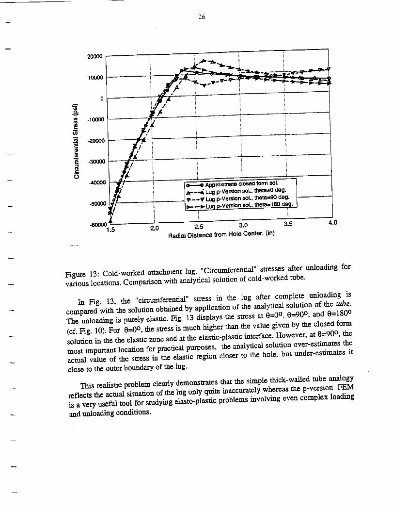
Figure 13: Cold-worked attachment lug. _ircun_erenu stresses after unloading for
various locations. Comparison with analytical solution of cold-worked tube.
In Fig. 13, the "circumferential" stress in the lug after complete unloading is
compared with the solution obtained by application of the analytical solution of the tube.
The unloading is purely elastic. Fig. 13 displays the stress at 0--0 °, 0--90 °, and 0=180 °
(cf. Fig. 10). For 0=0 °, the stress is much higher than the value given by the closed form
solution in the the elastic zone and at the elastic-plastic interface. However, at 0--90 °, the
most important location for practical purposes, the analytical solution over-estimates the
actual value of the stress in the elastic region closer to the hole, but under-estimates it
close to the outer boundary of the lug.
This realistic problem clearly demonstrates that the simple thick-walled robe analogy
reflects the actual situation of the lug only quite inaccurately whereas the p-version FEM
is a very useful tool for studying elasto-plastic problems involving even complex loading
and unloading conditions.
27
Conclusions
We conclude that the p-version of the finite element method performs very well in
small-strain incremental elasto-plastic analysis of structures. The p-version makes it a lot
easier to control the discretization error of the finite element method. Error monitoring
and control is achieved automatically, with minimum user interaction, and without
substantial loss of computational efficiency. In some cases, we find that the models based
on the p-version yield clearly superior accuracy in comparison with their h-version
counterparts.
As an example, the paper demonstrates the application of the p-version of the FEM to
the cold-working problem. It is seen that the method is very well suited for this practically
relevant problem and that reliable and realistic results can be obtained with a small
amount of modeling work.
In summary, the application of the p-version in elasto-plastic structural analysis can
be recommended.
-- 28
References
[11
[2]
[31
[41
[5]
[6]
[7]
[8]
[91
[101
[11]
[12]
[131
[141
[151
[161
[171
Chen, W.F.; Ha_n, D.J.: Plasticity for structural engineers. Springer, Berlin-New
York-Heidelberg, 1988.
Strang, G.; Fix, G.J.: An analysis of the f'mite element method, Prentice-Hall,
Englewood Cliffs N.J., 1973Zienkiewicz, O.C.: The finite element method, 3rd ed., McGraw-Hill, London,
1977.
Johnson, C.; Hansbo, P.: Adaptive finite element methods in computational
mechanics. Comp. Meth. Appl. Mech. Eng. (101), 143-181, 1992.
Stein, E.; Zhang, G.; Huang, Y.: Modeling and computation of shakedown
problems for nonlinear hardening materials. Comp. Meth. Appl. Mech. Eng.
(103), 247-272, 1993.Szabo, B.A.; Babuska, I.: Finite element analysis. John Wiley&Sons, New York,
1991.
Holzer, S.M.: Das symmetrische Randelementverfahren: Numerische Realisierung
und Kopplung mit der Fimte-Elemente-Methode zur elastoplastischen
Strukturanalyse. Doctoral thesis, Technische Universit/it Miinchen, Berichte aus
dem Konstruktiven Ingenieurbau 5/92 (ed. W. Wunderlich et al.), Munich, 1992.
Szabo, B.A.; Actis, R.L.; Holzer, S.M.: Solution of elastic-plastic stress analysis
problems by the p-version of the finite element method, Technical Note
WU/CCM-93/3, Center for Computational Mechanics, Washington University, St.
Louis, Missouri, 1993.
Katchanov, L.M.: Fundamentals of the theory of plasticity, MIR publishers,
Moscow, 1974.
Yosibash, Z.; Szabo, B.A.: Convergence of stress maxima in finite element
computations. Technical Note WU/CCM-93/2, Center tbr Computational
Mechanics, Washington University, St. Louis, Missouri, 1993 (submitted to
Comm. Num. Meth. Eng.).
Krieg, R.D.; Krieg, D.B.: Accuracies of numerical solution methods for the
elastic-perfectly plastic model. ASME J. Press. Vess. Techn., 510-515, 1977.
Sloan, S.W.: Substepping schemes for the numerical integration of elastoplastic
stress-strain relations. Int. J. Num. Meth. Eng. (24), 893-911, 1987.
Hodge, Ph. G.: Automatic piecewise linearization in ideal plasticity. Comp. Meth.
Appl. Mech. Eng. (10), 249-272, 1977.Ortiz, M.; Simo, J.C.: An analysis of a new class of integration algorithms for
elastoplastic constituitve relations. Int. J. Num. Meth. Eng. (23), 353-366, 1986.
Naagtegal, J.C.; Parks, D.M.; Rice, J.R.: On numerically accurate finite element
solutions in the fully plastic range. Comp. Meth. Appl. Mech. Eng. (4), 153-177,
1974.
Babuska, I.; Sud, M.: On locking in the finite element method. SIAM J. Numer.
Anal. (29), No. 5, 1261-1293, 1992.Babuska, I.; Suri, M.: Locking effects in the finite element approximation of
elasticity problems. Numer. Math. (62), 439-463, 1992.
i
29
[18]
[19]
[20]
[21]
[22]
Vogelius, M.: An analysis of the p-version of the f'mite element method for nearly
incompressible materials. Uniformly valid optimal error estimates. Numer. Math.
(41), 39-53, 1983.
Prager, W.; Hodge, Ph. G.: Theory of perfectly plastic solids, John Wiley&Sons,
New York, 1951.
Rich, D.L.; Impellizzeri, L.F.: Fatigue analysis of cold-worked and interference-fit
fastener holes. In: Cyclic stress-strain and plastic deformation aspects of fatigue
crack growth, Americam Society of Testing Materials, Special Technical
Publication 637, 1977.
ADINA User's Manual, ADINA R&D, Inc., Watertown, Massachusetts, 1992.
Sussmann, Th.; Bathe, K.-L: A finite element formulation for nonlinear
incompressible elastic and inelastic analysis. Computers & Structures (26), 357-
409, 1987.


