Embed Size (px)
Citation preview
The Next Generation Challenge for SoftwareDefined Radio
Mark Woh1, Sangwon Seo1, Hyunseok Lee1, Yuan Lin1, Scott Mahlke1,Trevor Mudge1, Chaitali Chakrabarti2, and Krisztian Flautner3
1 University of Michigan - Ann Arbor, Ann Arbor MI, USA2 Arizona State University, Tempe, AZ, USA
3 ARM Ltd., Cambridge, UK
Abstract. Wireless communication for mobile terminals has been a highperformance computing challenge. It requires almost super computer per-formance while consuming very little power. This requirement is beingmade even more challenging with the move to Fourth Generation (4G)wireless communication. It is projected that by 2010, 4G will be availablewith data rates from 100Mbps to 1Gbps. These data rates are orders ofmagnitude greater than current 3G technology and, consequently, willrequire orders of magnitude more computation power. Leading forerun-ners for this technology are protocols like 802.16e (mobile WiMAX) and3GPP LTE.
This paper presents an analysis of the major algorithms that comprisethese 4G technologies and describes their computational characteristics.We identify the major bottlenecks that need to be overcome in order tomeet the requirements of this new technology. In particular, we show thattechnology scaling alone of current Software Defined Radio architectureswill not be able to meet these requirements. Finally, we will discusstechniques that may make it possible to meet the power/performancerequirements without giving up programmability.
1 Introduction
The Third Generation Wireless age (3G) has provided an increase in data rateto the user which allows them to experience more than just voice over the air.Fourth Generation (4G) wireless networks is aimed at increasing that data rateby an order of magnitude in order to allow for users to experience richer con-tent and get true mobility, freeing themselves from the need for wires or WiFinetworks. The International Telecommunications Union (ITU) released a recom-mendation ITU-R M.1645 which sets data rate goals for 4G. They proposed amaximum data rate of 100Mbps for high mobility situations and 1Gbps for sta-tionary and low mobility situations like hot spots. These targets are being usedby most research on 4G today. It is also envisioned that 4G will include earlierstandards and their protocols, and that they will work harmoniously together.SDR solutions can help reduce the cost of systems, which are required to supportsuch a wide range of existing wireless technologies.
S. Vassiliadis et al. (Eds.): SAMOS 2007, LNCS 4599, pp. 343–354, 2007.c© Springer-Verlag Berlin Heidelberg 2007

344 M. Woh et al.
Fig. 1. The physical layer for a 4G terminal
Previous papers have characterized the computational requirments of 3G [1].There have been several proposals for SDR architectures capable of support-ing 3G W-CDMA and 802.11 physical layers. Examples are Sandbridge’s Sand-blaster [2] and SODA [3]. But these architectures are not able to handle thealmost 10-1000x increase in throughput required for 4G systems. This paperoutlines the 4G physical layer. The aim is to show the requirements that areneeded to process the new 4G physical layer and also to identify computationalpatterns that might suggest an architecture that can support 4G.
The 4G system we will study is based on orthogonal frequency division multi-plexing (OFDM) that uses a 1024-point FFT/IFFT, a 4x4 16QAM multiple inputmultiple output (MIMO) antenna system, and a low density parity (LDPC) en-coder and decoder. Detailed analysis of the major algorithms that make up thesecomponents and their computational characteristics show the following repeatedcomputational pattern: load data from a memory element (initially this is the re-ceived data), permuting that data, performing one or two ALU operations, andstoring the processed data back to memory. These patterns are similar to thosefound in 3G kernels. The architectures that are designed to support them, suchas SODA, will not be able to meet the 4G requirements through technology scal-ing alone. As we will show, other techniques will have to be enlisted such as widerSIMD engines, special purpose functional units, and special memory systems.
This paper is organized as follows. In the next section, we begin by present-ing a simplified 4G system and by describing some of major kernels: an OFDMmodulator/demodulator, a MIMO modulator/demodulator, and a channel de-coder for LDPC. In section 3, we give a brief overview of SODA and use it as abaseline to identify the dominate workload profiles and common computationalpatterns of the kernels. In section 4, we present programmable hardware supportfor implementing these kernels efficiently to meet the high throughput requiredfor 4G. The summary and concluding remarks are given in section 5.
2 4G Physical Layer
Figure 1 shows a 4G wireless terminal. Like other wireless communication sys-tem, its major blocks are a channel encoder/decoder and a modulator/demodulator. The role of the channel encoder is forward error correction thatenables receivers to correct errors without retransmission. Modulation maps in-put data sequence onto signal waveforms which are specifically designed for thewireless channel. Demodulation estimates the transmitted data sequence from
The Next Generation Challenge for Software Defined Radio 345
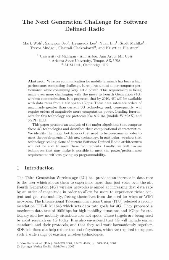
(a) Data movement patterns(b) Computation patterns
Fig. 2. The data movement of an 8 point FFT and the computations in a 2 point FFT
the received waveform, which have been corrupted by noise and interferencewhen they traversed the wireless channel.
In order to satisfy the gigabit level throughput requirement, 4G systems em-ploy three techniques not found together in 3G: 1) orthogonal frequency divisionmultiple access (OFDMA); 2) MIMO to support multiple antennas; and 3) LDPCcodes for the channel encoder/decoder.
2.1 OFDMA
OFDMA is a modulation scheme which transmits input signals over multiplenarrow sub-channels. Both modulation and demodulation in OFDMA systemscan be implemented with fast fourier transforms (FFT). Although additionalsynchronization procedures are required in OFDMA receivers, we can ignorethem because their contribution is small.
FFT. As shown in Figure 1, the transmitter uses an inverse FFT (IFFT) formodulation and the receiver uses an FFT for demodulation. Because FFT andIFFT are almost identical, we will just analyze the FFT.
The FFT operation consists of a data movement followed by multiplicationand addition on a complex number. If we assume an N point FFT, it consists oflog2 N stages. As an example, Figure 2.1 shows the data movement pattern ofan 8 point FFT. It consists of 3 stages. Each stage shows a different but regulardata movement pattern. The operation of each stage can be divided into several2 point FFT operation as depicted in Figure 2.1.
The FFT allows wide data level parallelism because all 2 point FFT operationsrequired for proceeding from one stage to the next can be done in parallel. Itis important to exploit this type of data level parallelism to meet power andperformance requirements of 4G system, because the FFT width of 4G systemscan be as large as 2048.
2.2 MIMO
MIMO is a technique that uses multiple antennas both for the transmissionand reception. It can be used for two purposes: signal quality enhancement by
346 M. Woh et al.
Timeslot, T
AntennaTx 1 Tx 2
1
2
x1 x2
-x2* x1*
(a) Transmission Matrix—the * in-dicates complex conjugate.
ComplexConjugate Negation
ComplexConjugate
Antenna 2
Antenna 1x[0]
x[1]
x[0]
x[1]
y[0]
y[1]
y[0]
y[1]
(b) Computation patterns of an STBC encoder
ComplexMultiply Accumulate
ChannelEstimation
H2[1], H1[1], H2[0], H1[0]
Y*1[1], Y1[0]
Y*2[1], Y2[0]
Receiver Antenna 1 and 2
X[1], X[0]
Conjugate+Negation
(c) Computation pattern of an STBC decoder
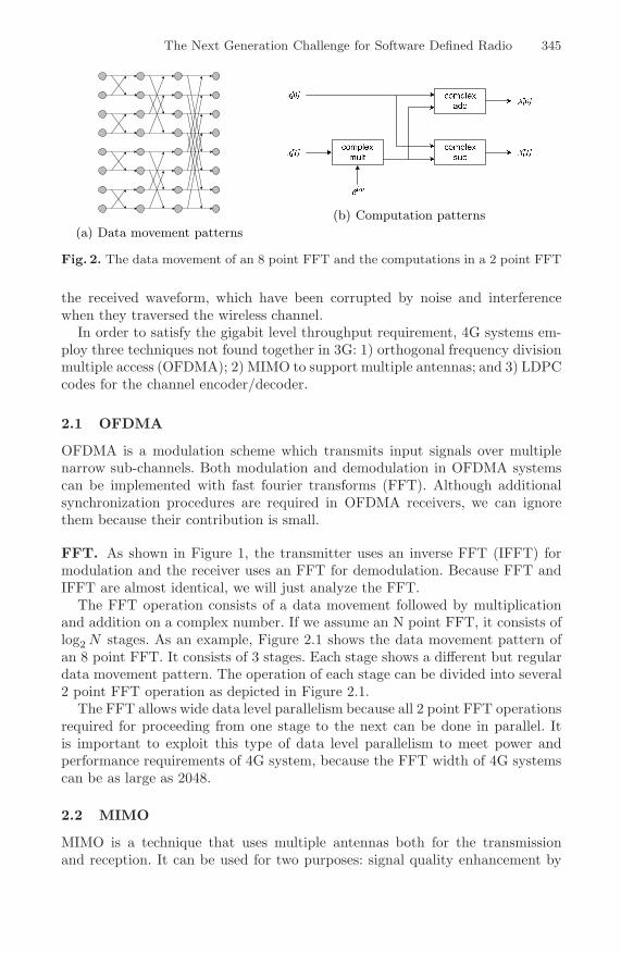
Fig. 3. Transmission code matrix and computation patterns of the Alamouti 2x2 STBC
transmitting identical signal through multiple antennas and channel capacityenhancement by transmitting different signals on multiple antennas. Space timeblock codes (STBC) is a popular MIMO technique for the signal quality en-hancement and the vertical Bell Laboratories layered space-time (V-BLAST)technique is popular for channel capacity enhancement.
STBC. This is used to increase the signal quality by transmitting the samesignal multiple times through different antennas. Signal quality is increased byreceiving those redundant copies of the same signal and using the informationfrom each receiver to optimally combine them to produce a better signal. Theimplementation we used is based on Alamouti’s 2x2 scheme [4], which uses 2transmit and 2 receive antennas.
STBC Encoder. The encoder orders and transmits data based on the transmis-sion matrix shown in figure 3(a). The operation consists of transmitting twodifferent symbols at the first time instance, then transmitting the conjugate ofthe same two symbols with antennas switched (see the matrix in figure 3(a)).Figure 3(b) shows the computation needed to perform this operation. First thedata is sent to each modulator and then the conjugate and negation are per-formed. This corresponds to a simple predication operation to obtain the realand imaginary values. This is highly parallelizable, and a 1024 point FFT couldbe run in parallel on a 1024 wide SIMD (Single Instruction, Multiple Data)processor.
STBC Decoder. The decoder takes the transmitted data from both time in-stances and combines them together to create the original two symbols. The
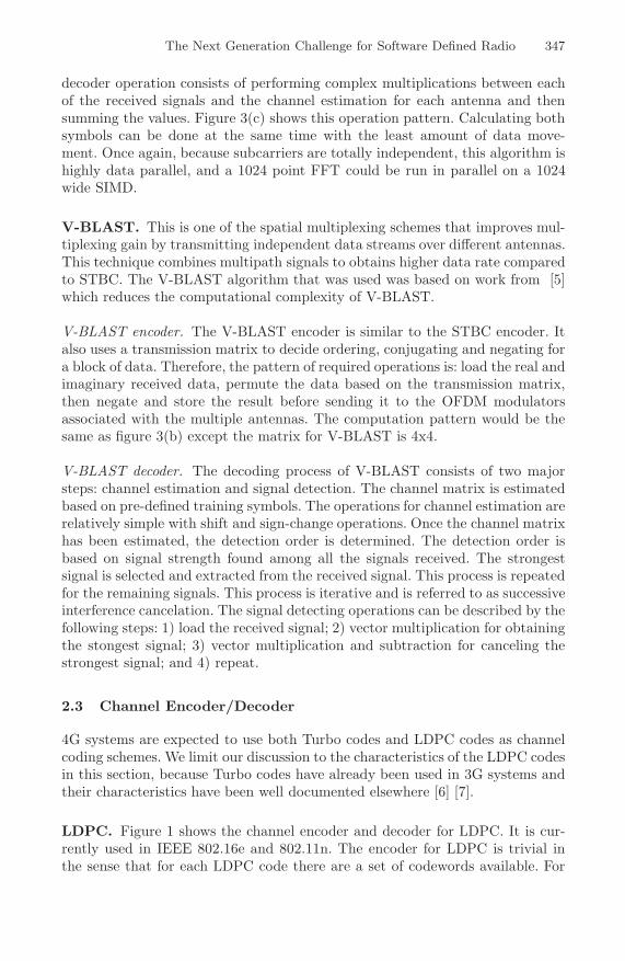
The Next Generation Challenge for Software Defined Radio 347
decoder operation consists of performing complex multiplications between eachof the received signals and the channel estimation for each antenna and thensumming the values. Figure 3(c) shows this operation pattern. Calculating bothsymbols can be done at the same time with the least amount of data move-ment. Once again, because subcarriers are totally independent, this algorithm ishighly data parallel, and a 1024 point FFT could be run in parallel on a 1024wide SIMD.
V-BLAST. This is one of the spatial multiplexing schemes that improves mul-tiplexing gain by transmitting independent data streams over different antennas.This technique combines multipath signals to obtains higher data rate comparedto STBC. The V-BLAST algorithm that was used was based on work from [5]which reduces the computational complexity of V-BLAST.
V-BLAST encoder. The V-BLAST encoder is similar to the STBC encoder. Italso uses a transmission matrix to decide ordering, conjugating and negating fora block of data. Therefore, the pattern of required operations is: load the real andimaginary received data, permute the data based on the transmission matrix,then negate and store the result before sending it to the OFDM modulatorsassociated with the multiple antennas. The computation pattern would be thesame as figure 3(b) except the matrix for V-BLAST is 4x4.
V-BLAST decoder. The decoding process of V-BLAST consists of two majorsteps: channel estimation and signal detection. The channel matrix is estimatedbased on pre-defined training symbols. The operations for channel estimation arerelatively simple with shift and sign-change operations. Once the channel matrixhas been estimated, the detection order is determined. The detection order isbased on signal strength found among all the signals received. The strongestsignal is selected and extracted from the received signal. This process is repeatedfor the remaining signals. This process is iterative and is referred to as successiveinterference cancelation. The signal detecting operations can be described by thefollowing steps: 1) load the received signal; 2) vector multiplication for obtainingthe stongest signal; 3) vector multiplication and subtraction for canceling thestrongest signal; and 4) repeat.
2.3 Channel Encoder/Decoder
4G systems are expected to use both Turbo codes and LDPC codes as channelcoding schemes. We limit our discussion to the characteristics of the LDPC codesin this section, because Turbo codes have already been used in 3G systems andtheir characteristics have been well documented elsewhere [6] [7].
LDPC. Figure 1 shows the channel encoder and decoder for LDPC. It is cur-rently used in IEEE 802.16e and 802.11n. The encoder for LDPC is trivial inthe sense that for each LDPC code there are a set of codewords available. For
348 M. Woh et al.
L0 L1 L2 L3 L4 L5 L6 L7
E0 E1 E2 E3
Bit Nodes
Check Nodes
L0,0
E0,0 E3,0 E6,0 E7,0
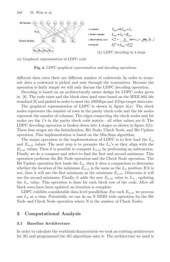
(a) Graphical representation of LDPC code
(b) LDPC decoding in 4 steps
Fig. 4. LDPC graphical representation and decoding operations
different data rates there are different number of codewords. In order to trans-mit data a codeword is picked and sent through the transmitter. Because theoperation is fairly simple we will only discuss the LDPC decoding operation.
Decoding is based on an architecturally aware design for LDPC codes givenin [8]. The code rates and the block sizes used were based on the IEEE 802.16estandard [9] and picked in order to meet the 100Mbps and 1Gbps target data rate.
The graphical representation of LDPC is shown in figure 4(a). The checknodes represents the number of rows in the parity check code and the bit nodesrepresent the number of columns. The edges connecting the check nodes and bitnodes are the 1’s in the parity check code matrix—all other values are 0. TheLDPC decoding operation is broken down into 4 stages as shown in figure 4(b).These four stages are the Initialization, Bit Node, Check Node, and Bit Updateoperation. This implementation is based on the Min-Sum algorithm.
The major operation in the implementation of LDPC is to first load the Ln
and En,m values. The next step is to permute the Ln’s so they align with theEn,m values. Then it is possible to compute Ln,m by performing an subtraction.Finally we do a compare and select to find the first and second minimum. Thisoperation performs the Bit Node operation and the Check Node operation. TheBit Update operation first loads the Ln, then it does a comparison to determinewhether the location of the minimum En,m is the same as the Ln position. If it isnot, then it will use the first minimum as the minimum En,m. Otherwise it willuse the second minimum. Finally, it adds the new En,m value to Ln , updatingthe Ln value. This operation is done for each block row of the code. After allblock rows have been updated an iteration is complete.
LDPC exhibits considerable data level parallelism. For each En,m we processone Ln at a time. Potentially we can do an N SIMD wide operation for the BitNode and Check Node operation where N is the number of Check Nodes.
3 Computational Analysis
3.1 Baseline Architecture
In order to calculate the workload characteristic we took an existing architecturefor 3G and programmed the 4G algorithms onto it. The architecture we used is
The Next Generation Challenge for Software Defined Radio 349
512-bit
SIMD
Reg.
File
E
X
512-bit
SIMD
ALU+
Mult
SIMD
Shuffle
Net-
work
(SSN)
W
B
Scalar
ALU
W
B
E
X
Scalar
RF
Local
SIMD
Memory
Local
Scalar
Memory
S
T
V
AGU
RFE
X
W
BAGUALU
1. SIMD pipeline
2. Scalar pipeline
4. AGU pipeline
V
TS
Pred.
Regs
W
B
SIMD
to
Scalar
(VtoS)ALU
RF
DMA
SODA
PE
5. DMA
3. Local
memory
Local
MemoriesExecution
Unit
Inte
rco
nn
ect
Bu
s
Global
Scratchpad
Memory
Control
Processor
SODA System
To
System
Bus
PE
Local
MemoriesExecution
Unit
PE
Local
MemoriesExecution
Unit
PE
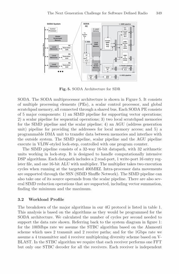
Fig. 5. SODA Architecture for SDR
SODA. The SODA multiprocessor architecture is shown in Figure 5. It consistsof multiple processing elements (PEs), a scalar control processor, and globalscratchpad memory, all connected through a shared bus. Each SODA PE consistsof 5 major components: 1) an SIMD pipeline for supporting vector operations;2) a scalar pipeline for sequential operations; 3) two local scratchpad memoriesfor the SIMD pipeline and the scalar pipeline; 4) an AGU (address generationunit) pipeline for providing the addresses for local memory access; and 5) aprogrammable DMA unit to transfer data between memories and interface withthe outside system. The SIMD pipeline, scalar pipeline and the AGU pipelineexecute in VLIW-styled lock-step, controlled with one program counter.
The SIMD pipeline consists of a 32-way 16-bit datapath, with 32 arithmeticunits working in lock-step. It is designed to handle computationally intensiveDSP algorithms. Each datapath includes a 2 read-port, 1 write-port 16 entry reg-ister file, and one 16-bit ALU with multiplier. The multiplier takes two executioncycles when running at the targeted 400MHZ. Intra-processor data movementsare supported through the SSN (SIMD Shuffle Network). The SIMD pipeline canalso take one of its source operands from the scalar pipeline. There are also sev-eral SIMD reduction operations that are supported, including vector summation,finding the minimum and the maximum.
3.2 Workload Profile
The breakdown of the major algorithms in our 4G protocol is listed in table 1.This analysis is based on the algorithms as they would be programmed for theSODA architecture. We calculated the number of cycles per second needed tosupport the data rate shown. Referring back to the system diagram in figure 1:for the 100Mbps rate we assume the STBC algorithm based on the Alamoutischeme which uses 2 transmit and 2 receive paths; and for the 1Gbps rate weassume a 4 transmitter and 4 receiver multiplexing diversity scheme based on V-BLAST. In the STBC algorithm we require that each receiver performs one FFTbut only one STBC decoder for all the receivers. Each receiver is independent
350 M. Woh et al.
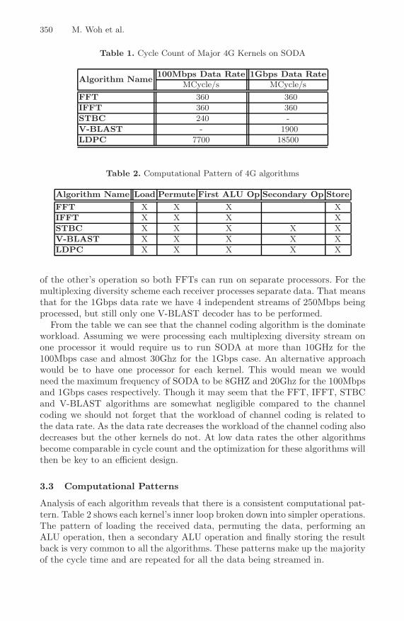
Table 1. Cycle Count of Major 4G Kernels on SODA
Algorithm Name100Mbps Data Rate 1Gbps Data Rate
MCycle/s MCycle/sFFT 360 360IFFT 360 360STBC 240 -V-BLAST - 1900LDPC 7700 18500
Table 2. Computational Pattern of 4G algorithms
Algorithm Name Load Permute First ALU Op Secondary Op Store
FFT X X X XIFFT X X X XSTBC X X X X XV-BLAST X X X X XLDPC X X X X X
of the other’s operation so both FFTs can run on separate processors. For themultiplexing diversity scheme each receiver processes separate data. That meansthat for the 1Gbps data rate we have 4 independent streams of 250Mbps beingprocessed, but still only one V-BLAST decoder has to be performed.
From the table we can see that the channel coding algorithm is the dominateworkload. Assuming we were processing each multiplexing diversity stream onone processor it would require us to run SODA at more than 10GHz for the100Mbps case and almost 30Ghz for the 1Gbps case. An alternative approachwould be to have one processor for each kernel. This would mean we wouldneed the maximum frequency of SODA to be 8GHZ and 20Ghz for the 100Mbpsand 1Gbps cases respectively. Though it may seem that the FFT, IFFT, STBCand V-BLAST algorithms are somewhat negligible compared to the channelcoding we should not forget that the workload of channel coding is related tothe data rate. As the data rate decreases the workload of the channel coding alsodecreases but the other kernels do not. At low data rates the other algorithmsbecome comparable in cycle count and the optimization for these algorithms willthen be key to an efficient design.
3.3 Computational Patterns
Analysis of each algorithm reveals that there is a consistent computational pat-tern. Table 2 shows each kernel’s inner loop broken down into simpler operations.The pattern of loading the received data, permuting the data, performing anALU operation, then a secondary ALU operation and finally storing the resultback is very common to all the algorithms. These patterns make up the majorityof the cycle time and are repeated for all the data being streamed in.
The Next Generation Challenge for Software Defined Radio 351
0100020003000400050006000700080009000
180nm 130nm 90nm 65nm 45nm 32nm 22nm
Fre
quen
cy (
Mhz
)
0
0.1
0.2
0.3
0.4
0.5
0.6
0.7
0.8
Pow
er (
W)
Scaled Frequency Scaled Power
(a) Technology Scaled SODA
180nm 130nm 90nm 65nm 45nm 32nm 22nm
1.8 1.3 1.1 1.1 1 0.9 0.8
TechnologyNode
Vdd (V)
(b) Vdd Voltage Scaling
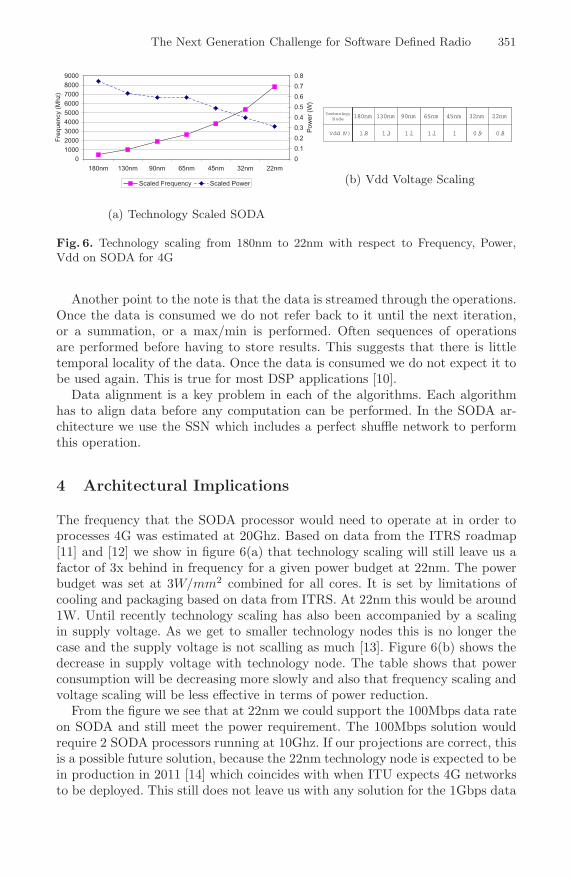
Fig. 6. Technology scaling from 180nm to 22nm with respect to Frequency, Power,Vdd on SODA for 4G
Another point to the note is that the data is streamed through the operations.Once the data is consumed we do not refer back to it until the next iteration,or a summation, or a max/min is performed. Often sequences of operationsare performed before having to store results. This suggests that there is littletemporal locality of the data. Once the data is consumed we do not expect it tobe used again. This is true for most DSP applications [10].
Data alignment is a key problem in each of the algorithms. Each algorithmhas to align data before any computation can be performed. In the SODA ar-chitecture we use the SSN which includes a perfect shuffle network to performthis operation.
4 Architectural Implications
The frequency that the SODA processor would need to operate at in order toprocesses 4G was estimated at 20Ghz. Based on data from the ITRS roadmap[11] and [12] we show in figure 6(a) that technology scaling will still leave us afactor of 3x behind in frequency for a given power budget at 22nm. The powerbudget was set at 3W/mm2 combined for all cores. It is set by limitations ofcooling and packaging based on data from ITRS. At 22nm this would be around1W. Until recently technology scaling has also been accompanied by a scalingin supply voltage. As we get to smaller technology nodes this is no longer thecase and the supply voltage is not scalling as much [13]. Figure 6(b) shows thedecrease in supply voltage with technology node. The table shows that powerconsumption will be decreasing more slowly and also that frequency scaling andvoltage scaling will be less effective in terms of power reduction.
From the figure we see that at 22nm we could support the 100Mbps data rateon SODA and still meet the power requirement. The 100Mbps solution wouldrequire 2 SODA processors running at 10Ghz. If our projections are correct, thisis a possible future solution, because the 22nm technology node is expected to bein production in 2011 [14] which coincides with when ITU expects 4G networksto be deployed. This still does not leave us with any solution for the 1Gbps data
352 M. Woh et al.
rate. However, there are many features of the algorithms which we can exploitarchitecturally to help us reach the goal of 1Gbps and still retain the flexibilityof a programmable SDR processor.
Multi-Processor. Most of the 4G algorithms can be divided onto multipleprocessors especially for FFT, and STBC, and even LDPC. The workload canbe divided evenly among the processors. However, as we subdivide the algorithmsacross processes we get an increase in data communication. Although each stageof an algorithm is highly data parallel, stages requires data movement betweendifferent subcarriers in the FFT and between different check nodes in the LDPC.As we subdivide the algorithms, communication will increase, but, because theoperations of each stage are streamed, we may be able to hide the latency of thiscommunication under the computations itself. This would require an efficientrouting and interconnect network and also scheduling that would be able tomeet the constraints of data communication when multiple processors are used.
By dividing the workload across multiple processors we would be able to meetthe frequency target for the 4G 1Gbps workload but we would still be 3x off thepower budget. Multicore designs themselves cannot solve the problem of meetingthe 4G requirement.
Wider SIMD. Increasing the SIMD width of the processors takes advantage ofthe highly data parallel nature of the algorithms. Based on historical transistorgrowth, at the 22nm node we can expect to grow from a 32 wide SIMD to a2048 wide SIMD machine. This assumes a fixed area constraint. This increase inwidth would allow us to reduce the cycle count to compute any size FFT as longas N is greater than or equal to the SIMD width. For FFT, the data movementcan be accomplished by the SSN shuffle network.
For LDPC this increase in SIMD would also be beneficial because we canprocess more parity check nodes for LDPC at once. LDPC though would notgain the same data movement advantages as FFT, because it needs to align thecheck nodes and the bit nodes. However, this would not increase the amount ofdata movement dramatically.
STBC would also benefit, because it would be possible to process more sub-carriers at one time. Because there is little data movement within the STBC wecan expect gains equal to the increase in width.
Special Purpose Functional Units. Currently in SODA the operations areRISC like in that after every instruction is simple and then writes back to theregister file. This can be costly in terms of power and latency, because, as westated earlier, the algorithms are streaming in nature. Writing back the datamay not be very efficient. This suggests that functional units that chain opera-tions will be beneficial not only in performance but also power. There has beenwork [15] that shows that using special functional units to streamline commonoperational patterns may not only increase performance but also will be morearea and energy-efficient.
The Next Generation Challenge for Software Defined Radio 353
LDPC would also benefit from having special minimum and maximum regis-ters embedded into the ALU. For each row operation of the parity check matrixthat is performed the result will be compared with the current state of theregister and swapped if the condition is met. In comparison with SODA, by im-plementing this special functional unit, LDPC can be reduce in cycle count byabout 30 percent.
Memory System. Most of the algorithms like LDPC, FFT and STBC all treateach row of the SIMD as independent. The data is loaded from memory thenpermuted and stored back. There is no instance in those algorithms where tworows have to access the same data at the same time. This suggests that thememory system does not have to be a large global shared memory. Instead itcan be divided into banks. Banking the memory as much as possible will reducethe cost of reading and writing data into a large global memory. Banking willallow us to reduce the size of each memory, increase the speed, and lower powerof the memory system. In algorithms like LDPC, which may need block sizesthat are larger than currently used, we would be able to efficiently scale the sizeof the memories too.
Algorithms would also benefit from a smarter memory systems that supportflexible gather/scatter accesses. Currently many cycles are wasted in LDPCaligning the check nodes and bit nodes. V-BLAST would also benefit, becausethe algorithm has to read and write back data in changing orders.
5 Conclusion
The power/performance requirements for 4G presents a significant challengefor computer architects, especially if some degree of programmability is to beretained. Currently technology is not capable of processing a 4G system on asingle processor. In this paper we have analyzed a 4G system in the contextof the SODA architecture and have shown that 3G solutions cannot meet theperformance of 4G even if technology scaling is taken into account. We havepresented architectural options that can improve the performance and reducethe power consumption of 4G solutions. We have argued that one solution tothe power/performance challenge for 4G will increase the number of cores, andthat each core will include a very wide SIMD processor with special purposefunction units and highly banked memories.
References
1. Lee, H., Lin, Y., Harel, Y., Woh, M., Mahlke, S.A., Mudge, T.N., Flautner, K.:Software defined radio - a high performance embedded challenge. In: Conte, T.,Navarro, N., Hwu, W.-m.W., Valero, M., Ungerer, T. (eds.) HiPEAC 2005. LNCS,vol. 3793, pp. 6–26. Springer, Heidelberg (2005)
2. Schulte, M., Glossner, J., Jinturkar, S., Moudgill, M., Mamidi, S., Vassiliadis, S.:A low-power multithreaded processor for software defined radio. J. VLSI SignalProcess. Syst. 43, 143–159 (2006)
354 M. Woh et al.
3. Lin, Y., Lee, H., Woh, M., Harel, Y., Mahlke, S.A., Mudge, T.N., Chakrabarti,C., Flautner, K.: Soda: A low-power architecture for software radio. In: ISCA, pp.89–101. IEEE Computer Society Press, Los Alamitos (2006)
4. Alamouti, S.M.: A simple transmit diversity technique for wireless communications.IEEE J. on Select Areas in Communications 16, 1451–1458 (1998)
5. Guo, Z., Nilsson, P.: A vlsi architecture of the square root algorithm for v-blastdetection. J. VLSI Signal Process. Syst. 44, 219–230 (2006)
6. Lin, Y., Mahlke, S., Mudge, T., Chakrabarti, C., Reid, A., Flautner, K.: Designand implementation of turbo decoders for software defined radio. In: SiPS, IEEEComputer Society Press, Los Alamitos (2006)
7. Lee, S.-J., Shanbhag, N.R., Singer, A.C.: A low-power vlsi architecture for turbodecoding. In: ISLPED ’03. Proceedings of the 2003 international symposium onLow power electronics and design, pp. 366–371. ACM Press, New York (2003)
8. Zhu, Y., Chakrabarti, C.: Architecture-aware ldpc code design for software definedradio. IEEE Workshop on Signal Processing Systems (2006)
9. http://www.ieee802.org/16/pubs/80216e.html10. Robelly, J.P., Seidel, H., Chen, K.C., Fettweis, G.: Energy efficiency vs. pro-
grammability trade-off: architectures and design principles. In: DATE ’06. Pro-ceedings of the conference on Design, automation and test in Europe, Leuven,Belgium. European Design and Automation Association, vol. 3001, pp. 587–592(2006)
11. http://public.itrs.net12. Rodriguez, S., Jacob, B.: Energy/power breakdown of pipelined nanometer caches
(90nm/65nm/45nm/32nm). In: ISLPED ’06. Proceedings of the 2006 internationalsymposium on Low power electronics and design, pp. 25–30. ACM Press, New York(2006)
13. McPherson, J.W.: Reliability challenges for 45nm and beyond. In: DAC ’06. Pro-ceedings of the 43rd annual conference on Design automation, pp. 176–181. ACMPress, New York (2006)
14. Chau, R., Doyle, B., Doczy, M., Datta, S., Hareland, S., Jin, B., Kavalieros, J.,Metz, M.: Silicon nano-transistors and breaking the 10 nm physical gate lengthbarrier. In: Device Research Conference, pp. 23–25 (2003)
15. Karnik, T., Borkar, S., De, V.: Sub-90nm technologies: challenges and opportu-nities for cad. In: ICCAD ’02. Proceedings of the 2002 IEEE/ACM internationalconference on Computer-aided design, pp. 203–206. ACM Press, New York (2002)