Embed Size (px)
Citation preview
DOI: http://dx.doi.org/10.1590/1516-1439.352914Materials Research. 2015; 18(Suppl 2): 148-153 © 2015
*e-mail: [email protected]
1. IntroductionThe appropriate selection and application of cutting
edge protection are the basic ingredients for the successful manufacturing with proper performance when using a cemented carbide tool (WC-Co). Cutting edge preparation, when properly carried out, increases the strength of the tool cutting edge and its lifetime, minimizes the possibility of built-up edge (BUE) formation and improves the surface quality of the produced part1.
One of the aspects that have guided researches and innovations for high-performance tools is the preparation of the main cutting edge2. The key motivation towards the development of a process for the preparation of the cutting edge by rounding (honing), chamfering or the combination of both, is to improve its microtopography. Thus adapting the surface of the cutting edge as well as the cutting surface for a subsequent coating process of the tool or improving the contact zone for machining2.
The geometry of the edge preparation influences the thermomechanic aspects of the cutting process. From which it is worth pointing out the format of the deformation zone, the temperature distribution in the cutting process, the machining forces, the chip formation and flow, the superficial integrity of the work piece and the tool’s resistance to wear2,3-6. Due to its importance in the machining field, cutting edge failures and some benefits related to the protection of the cutting edge achieved by different processes have been the subject of studies by several researchers7-12.
This paper aims to understand the influence that cutting edge preparation has on the quality of the obtained hole
and on the tool’s wear resistance when compared to a simply sharpened tool. Most authors have not addressed the quality of the obtained parts and very few of them have studied the effect of edge rounding in a drilling process. Cheung et al.8, for instance, also noted the lack of publications in this area, which is probably due to the high complexity of the drilling process.
2. Material and Experimental ProceduresThe machine used for conducting the machining tests
was a CNC vertical lathe manufactured by EMAG, model VSC-250. The cutting tools were prepared (sharpened) on a CNC grinding machine manufactured by Walter, model Power Production.
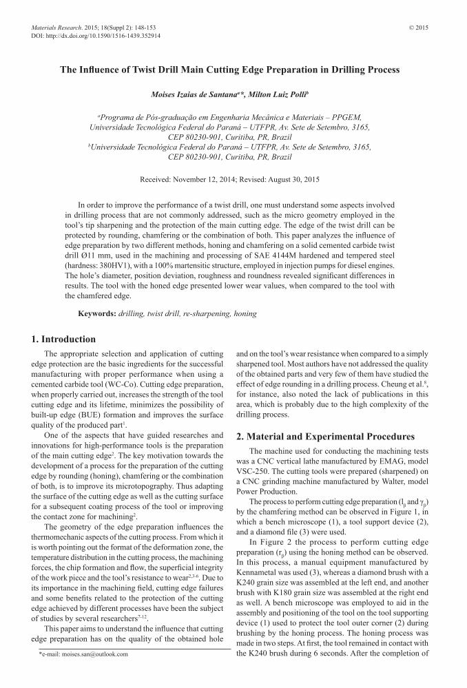
The process to perform cutting edge preparation (lβ and γβ) by the chamfering method can be observed in Figure 1, in which a bench microscope (1), a tool support device (2), and a diamond file (3) were used.
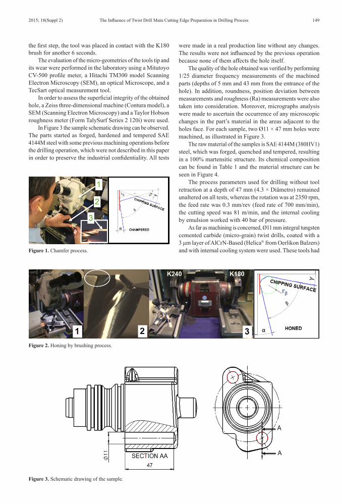
In Figure 2 the process to perform cutting edge preparation (rβ) using the honing method can be observed. In this process, a manual equipment manufactured by Kennametal was used (3), whereas a diamond brush with a K240 grain size was assembled at the left end, and another brush with K180 grain size was assembled at the right end as well. A bench microscope was employed to aid in the assembly and positioning of the tool on the tool supporting device (1) used to protect the tool outer corner (2) during brushing by the honing process. The honing process was made in two steps. At first, the tool remained in contact with the K240 brush during 6 seconds. After the completion of
The Influence of Twist Drill Main Cutting Edge Preparation in Drilling Process
Moises Izaias de Santanaa*, Milton Luiz Pollib
aPrograma de Pós-graduação em Engenharia Mecânica e Materiais – PPGEM, Universidade Tecnológica Federal do Paraná – UTFPR, Av. Sete de Setembro, 3165,
CEP 80230-901, Curitiba, PR, BrazilbUniversidade Tecnológica Federal do Paraná – UTFPR, Av. Sete de Setembro, 3165,
CEP 80230-901, Curitiba, PR, Brazil
Received: November 12, 2014; Revised: August 30, 2015
In order to improve the performance of a twist drill, one must understand some aspects involved in drilling process that are not commonly addressed, such as the micro geometry employed in the tool’s tip sharpening and the protection of the main cutting edge. The edge of the twist drill can be protected by rounding, chamfering or the combination of both. This paper analyzes the influence of edge preparation by two different methods, honing and chamfering on a solid cemented carbide twist drill Ø11 mm, used in the machining and processing of SAE 4144M hardened and tempered steel (hardness: 380HV1), with a 100% martensitic structure, employed in injection pumps for diesel engines. The hole’s diameter, position deviation, roughness and roundness revealed significant differences in results. The tool with the honed edge presented lower wear values, when compared to the tool with the chamfered edge.
Keywords: drilling, twist drill, re-sharpening, honing
The Influence of Twist Drill Main Cutting Edge Preparation in Drilling Process2015; 18(Suppl 2) 149
the first step, the tool was placed in contact with the K180 brush for another 6 seconds.
The evaluation of the micro-geometries of the tools tip and its wear were performed in the laboratory using a Mitutoyo CV-500 profile meter, a Hitachi TM300 model Scanning Electron Microscopy (SEM), an optical Microscope, and a TecSart optical measurement tool.
In order to assess the superficial integrity of the obtained hole, a Zeiss three-dimensional machine (Contura model), a SEM (Scanning Electron Microscopy) and a Taylor Hobson roughness meter (Form TalySurf Series 2 120i) were used.
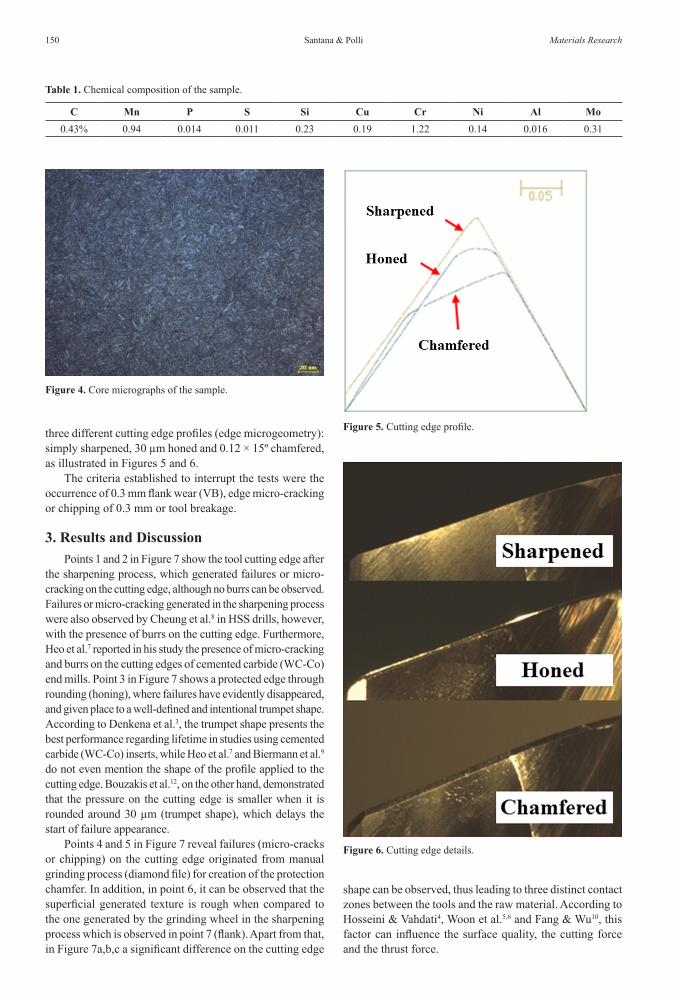
In Figure 3 the sample schematic drawing can be observed. The parts started as forged, hardened and tempered SAE 4144M steel with some previous machining operations before the drilling operation, which were not described in this paper in order to preserve the industrial confidentiality. All tests
were made in a real production line without any changes. The results were not influenced by the previous operation because none of them affects the hole itself.
The quality of the hole obtained was verified by performing 1/25 diameter frequency measurements of the machined parts (depths of 5 mm and 43 mm from the entrance of the hole). In addition, roundness, position deviation between measurements and roughness (Ra) measurements were also taken into consideration. Moreover, micrographs analysis were made to ascertain the occurrence of any microscopic changes in the part’s material in the areas adjacent to the holes face. For each sample, two Ø11 × 47 mm holes were machined, as illustrated in Figure 3.
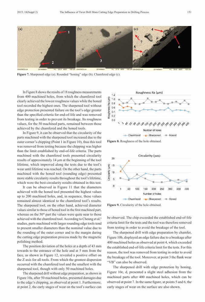
The raw material of the samples is SAE 4144M (380HV1) steel, which was forged, quenched and tempered, resulting in a 100% martensitic structure. Its chemical composition can be found in Table 1 and the material structure can be seen in Figure 4.
The process parameters used for drilling without tool retraction at a depth of 47 mm (4.3 × Diâmetro) remained unaltered on all tests, whereas the rotation was at 2350 rpm, the feed rate was 0.3 mm/rev (feed rate of 700 mm/min), the cutting speed was 81 m/min, and the internal cooling by emulsion worked with 40 bar of pressure.
As far as machining is concerned, Ø11 mm integral tungsten cemented carbide (micro-grain) twist drills, coated with a 3 µm layer of AlCrN-Based (Helica from Oerlikon Balzers) and with internal cooling system were used. These tools had Figure 1. Chamfer process.
Figure 2. Honing by brushing process.
Figure 3. Schematic drawing of the sample.
Santana & Polli150 Materials Research
three different cutting edge profiles (edge microgeometry): simply sharpened, 30 µm honed and 0.12 × 15º chamfered, as illustrated in Figures 5 and 6.
The criteria established to interrupt the tests were the occurrence of 0.3 mm flank wear (VB), edge micro-cracking or chipping of 0.3 mm or tool breakage.
3. Results and DiscussionPoints 1 and 2 in Figure 7 show the tool cutting edge after
the sharpening process, which generated failures or micro-cracking on the cutting edge, although no burrs can be observed. Failures or micro-cracking generated in the sharpening process were also observed by Cheung et al.8 in HSS drills, however, with the presence of burrs on the cutting edge. Furthermore, Heo et al.7 reported in his study the presence of micro-cracking and burrs on the cutting edges of cemented carbide (WC-Co) end mills. Point 3 in Figure 7 shows a protected edge through rounding (honing), where failures have evidently disappeared, and given place to a well-defined and intentional trumpet shape. According to Denkena et al.3, the trumpet shape presents the best performance regarding lifetime in studies using cemented carbide (WC-Co) inserts, while Heo et al.7 and Biermann et al.9 do not even mention the shape of the profile applied to the cutting edge. Bouzakis et al.12, on the other hand, demonstrated that the pressure on the cutting edge is smaller when it is rounded around 30 µm (trumpet shape), which delays the start of failure appearance.
Points 4 and 5 in Figure 7 reveal failures (micro-cracks or chipping) on the cutting edge originated from manual grinding process (diamond file) for creation of the protection chamfer. In addition, in point 6, it can be observed that the superficial generated texture is rough when compared to the one generated by the grinding wheel in the sharpening process which is observed in point 7 (flank). Apart from that, in Figure 7a,b,c a significant difference on the cutting edge
shape can be observed, thus leading to three distinct contact zones between the tools and the raw material. According to Hosseini & Vahdati4, Woon et al.5,6 and Fang & Wu10, this factor can influence the surface quality, the cutting force and the thrust force.
Table 1. Chemical composition of the sample.
C Mn P S Si Cu Cr Ni Al Mo0.43% 0.94 0.014 0.011 0.23 0.19 1.22 0.14 0.016 0.31
Figure 4. Core micrographs of the sample.
Figure 5. Cutting edge profile.
Figure 6. Cutting edge details.
The Influence of Twist Drill Main Cutting Edge Preparation in Drilling Process2015; 18(Suppl 2) 151
In Figure 8 shows the results of 18 roughness measurements from 400 machined holes, from which the chamfered tool clearly achieved the lowest roughness values while the honed tool recorded the highest ones. The sharpened tool without edge protection presented failure on the tool’s edge greater than the specified criteria for end-of-life and was removed from testing in order to prevent its breakage. Its roughness values, for the 50 machined parts, remained between those achieved by the chamfered and the honed tools.
In Figure 9, it can be observed that the circularity of the parts machined with the sharpened tool increased due to the outer corner’s chipping (Point 1 in Figure 10), thus this tool was removed from testing because the chipping was higher than the limit established by end-of-life criteria. The parts machined with the chamfered tools presented circularity results of approximately 14 µm at the beginning of the tool lifetime, which improved along the tests due to the tool’s wear until lifetime was reached. On the other hand, the parts machined with the honed tool (rounding edge) presented more stable circularity results throughout the tool’s lifetime, which were the best circularity results obtained in this test.
It can be observed in Figure 11 that the diameters achieved with the honed tool presented the highest values up to 200 machined holes, and, in sequence, these values remained almost identical to the chamfered tool’s results. The sharpened tool, on the other hand, achieved diameter values similar to those of honed tool in the first machined part, whereas on the 50th part the values were quite near to those achieved with the chamfered tool. According to Cheung et al.8 studies, parts machined with larger rounding edge tools tend to present smaller diameters than the nominal value due to the rounding of the outer corner and to the margin during the cutting edge preparation process made by the magnetic polishing method.
The position deviation of the holes at a depth of 43 mm towards to the entrance of the hole and at 5 mm from the face, as shown in Figure 12, revealed a positive offset on the Z axis for all tools. From which the greatest dispersion occurred with the chamfered tool and the smallest with the sharpened tool, though with only 50 machined holes.
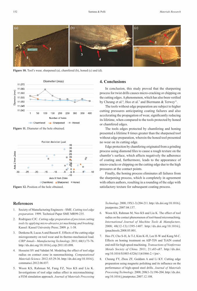
The sharpened drill without edge preparation, as shown in Figure 10a, after 50 machined holes, presented damages due to the edge’s chipping, as observed at point 1. Furthermore, at point 2, the early stages of wear on the tool’s surface can
be observed. The chip exceeded the established end-of-life criteria limit for the tests and the tool was therefore removed from testing in order to avoid the breakage of the tool.
The sharpened drill with edge preparation by chamfer, Figure 10b, displayed an edge failure due to a breakage after 400 machined holes as observed at point 4, which exceeded the established end-of-life criteria limit for the tests. For this reason, the tool was removed from testing in order to avoid the breakage of the tool. Moreover, at point 3 the flank wear “VB” can also be observed.
The sharpened drill with edge protection by honing, Figure 10c, d, presented a slight steel adhesion from the machined parts after 400 machined holes, which can be observed at point 7. In the same figure, at points 5 and 6, the early stages of wear on the surface are also shown.
Figure 7. Sharpened edge (a); Rounded “honing” edge (b); Chamfered edge (c).
Figure 8. Roughness of the hole obtained.
Figure 9. Circularity of the hole obtained.
Santana & Polli152 Materials Research
4. ConclusionsIn conclusion, this study proved that the sharpening
process for twist drills causes micro-cracking or chipping on the cutting edges. A phenomenon, which has also been verified by Cheung et al.8, Heo et al.7 and Biermann & Terwey11.
The tools without edge preparation are subject to higher cutting pressures anticipating coating failures and also accelerating the propagation of wear, significantly reducing its lifetime, when compared to the tools protected by honed or chamfered edges.
The tools edges protected by chamfering and honing presented a lifetime 8 times greater than the sharpened tool without edge preparation, wherein the honed tool presented no wear on its cutting edge.
Edge protection by chamfering originated from a grinding process using diamond files to cause a rough texture on the chamfer’s surface, which affects negatively the adherence of coating and, furthermore, leads to the appearance of micro-cracks or chipping on the cutting edge due to the high pressures at the contact points.
Finally, the honing process eliminates all failures from the sharpening process, which is completely in agreement with others authors, resulting in a rounding of the edge with satisfactory texture for subsequent coating process.
References1. Society of Manufacturing Engineers - SME. Cutting tool edge
preparation. 1999. Technical Paper SME MR99-235.
2. Rodriguez CJC. Cutting edge preparation of precision cutting tools by applying micro-abrasive jet machining and brushing. Kassel: Kassel University Press; 2009. p. 1-38.
3. Denkena B, Lucas A and Bassett E. Effects of the cutting edge microgeometry on tool wear and its thermo-mechanical load. CIRP Annals - Manufacturing Technology. 2011; 60(1):73-76. http://dx.doi.org/10.1016/j.cirp.2011.03.098.
4. Hosseini SV and Vahdati M. Modeling the effect of tool edge radius on contact zone in nanomachining. Computational Materials Science. 2012; 65:29-36. http://dx.doi.org/10.1016/j.commatsci.2012.06.037.
5. Woon KS, Rahman M, Fang FZ, Neo KS and Liu K. Investigations of tool edge radius effect in micromachining: a FEM simulation approach. Journal of Materials Processing
Figure 12. Position of the hole obtained.
Figure 10. Tool’s wear, sharpened (a), chamfered (b), honed (c) and (d).
Figure 11. Diameter of the hole obtained.
Technology. 2008; 195(1-3):204-211. http://dx.doi.org/10.1016/j.jmatprotec.2007.04.137.
6. Woon KS, Rahman M, Neo KS and Liu K. The effect of tool radius on the contact phenomenon of tool-based micromachinig. International Journal of Machine Tools & Manufacture. 2008; 48(12-13):1395-1407. http://dx.doi.org/10.1016/j.ijmachtools.2008.05.001.
7. Heo JY, Cho S-H, Je T-J, Kim K-H, Lee H-W and Kang M-C. Effects on honing treatment on AIP-TiN and TiAlN coated end-mill for high speed machining. Transactions of Nonferrous Metals Society of China. 2011; 21:s83-s87. http://dx.doi.org/10.1016/S1003-6326(11)61066-2.</jrn>.
8. Cheung FY, Zhou ZF, Geddam A and Li KY. Cutting edge preparation using magnetic polishing and its influence on the performance of high-speed steel drills. Journal of Materials Processing Technology. 2008; 208(1-3):196-204. http://dx.doi.org/10.1016/j.jmatprotec.2007.12.108.

The Influence of Twist Drill Main Cutting Edge Preparation in Drilling Process2015; 18(Suppl 2) 153
9. Biermann D, Wolf M and Aßmuth R. Cutting edge preparation to enhance the performance of single lip deep hole drills. Procedia CIRP. 2012; 1:172-177. http://dx.doi.org/10.1016/j.procir.2012.04.030.
10. Fang N and Wu Q. The effects of chamfered and honed tool edge geometry in machining of three aluminum alloys. International Journal of Machine & Manufacture. 2005; 45(10):1178-1187. http://dx.doi.org/10.1016/j.ijmachtools.2004.12.003.
11. Biermann D and Terwey I. Cutting edge preparation to improve tools for HPC process. CIRP Journal of Manufacturing Science and Technology. 2008; 1(2):76-80. http://dx.doi.org/10.1016/j.cirpj.2008.09.002.
12. Bouzakis KD, Michailidis N, Vidakis N, Efstathiou K, Leyendecker T, Erkens G, et al. Optimization of the cutting edge radius of PVD coated inserts in milling considering film fatigue failure mechanisms. Su rface and Coatings Technology. 2000; 133:501-507. http://dx.doi.org/10.1016/S0257-8972(00)00971-3.