Embed Size (px)
Citation preview
VI
THE EXTRUSION OF "'TEFLON "6TETRAFLUOROETHYLENE RESIN
FOR WIRE INSULATION
RECEN'VEDAUG 22 1967
CFSTIBY
D.N.DE YOUNG AND G.R.SNELI.NG
POLYCHEMICALS DEPARTMENT
E. I. DU PONT DE NEMOURS & COMPANY, INC.
"T•-• • =::•h•. -..= ,--,.ooaAuG i 1 1967for t•u *-c a'Jc. e'=;s /o
_ IC
00 EXTRUSION OF"TEFLON"* 6 TFTRAFLUOROETHYLENE RESINFOR WIRE INSULATION
By D. N. De Young and G. R. Snelling V
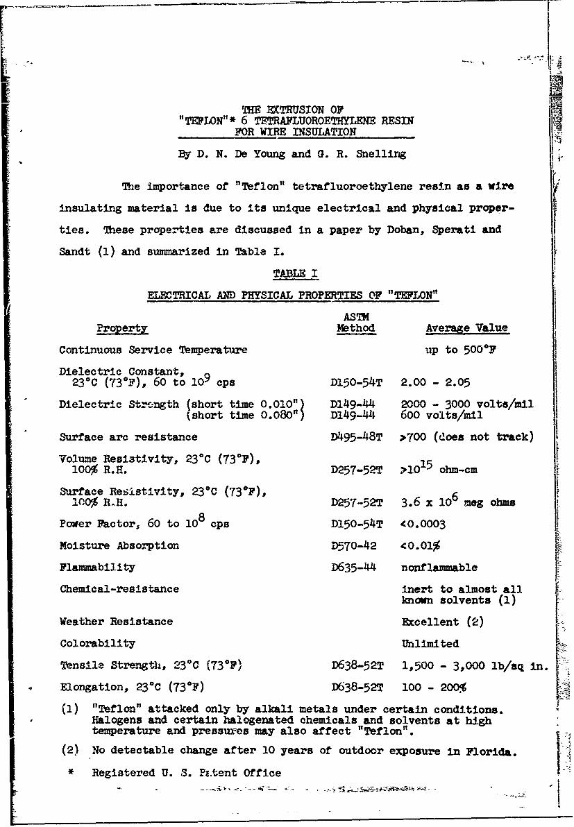
The importance of "Teflon" tetrafluoroethylene resin as a wire
insulating material is due to its unique electrical and physical proper-
ties. These properties are discussed in a paper by Doban, Sperati and
Sandt (1) and summarized in Table I.
TA•jLE I
ELECTRICAL AND PHYSICAL PROPERTIES OF "TEFLON"
ASTMProperty Method Average Value
Continuous Service Temperature up to 5000F
Dielectric Constant,230 C (73 0F), 60 to 109 cps D150-54T 2.00 - 2.05
Dielectric St-'ngth (short time 0.010") D149-44 2000 - 3000 volts/mil(short time 0.080") D149-4 600 volts/mil
Surface arc resistance D495-48T >TOO (does not track)
Volume Resistivity, 230 C (730F), 15100% R.H. D257-52T >10 ohm-cm
Surface Resistivity, 23°C (73°F),10,0% R.H. D257-52T 3.6 x 10⁶ meg ohms
Power Factor, 60 to 108 cps D150-54T 40.0003
Moisture Absorption D570-42 40.01%
Flammability D635-44 nonflammable
Chemical-resistance inert to almost allknown solvents (1)
Weather Resistance Excellent (2) [Colorability Unlimited
Tensile Strength, 23 0C (730p) D638-52T 1,500 - 3,000 lb/sq in.
Elongation, 23°C (730F) D638-52T 100 - 200%4
(1) "Teflon" attacked only by alkali metals under certain conditions.Halogens and certain halogenated chemicals and solvents at hightemperature and pressures may also affect "Teflon".
(2) No detectable change after 10 years of outdoor exposure in Florida.
* Registered U. S. Pf.tent Office
::SA A' -7-ý
"Teflon" is used principally for wire insulations which require
its excellent electrical properties at high and low service temperatures
as discussed by Ely (2) and Ondrejcin (3). Typical end use examples are
electronic hook-up wire, aircraft power wire, wire -,or corrosive areas,
coaxial cables, and wire for small electric motors.
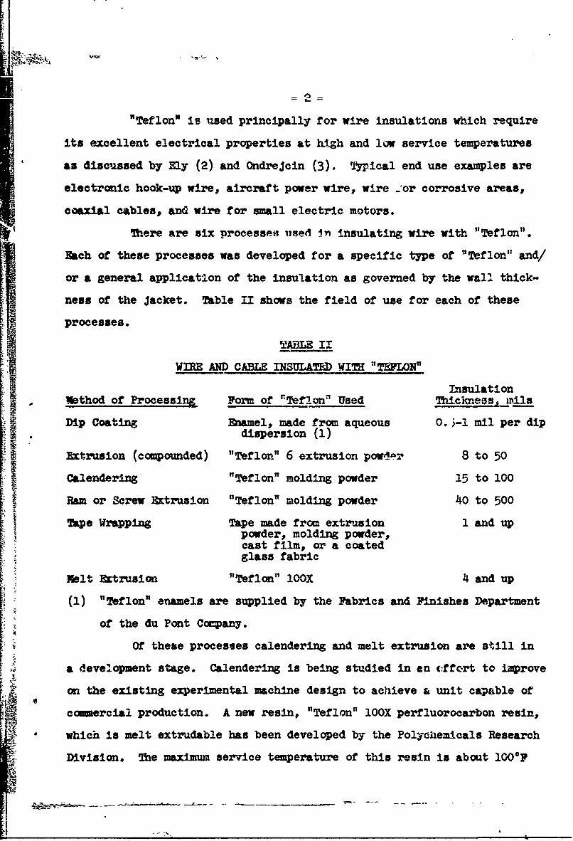
There are six processes used In insulating wire with "Teflon".
Each of these processes was developed for a specific type of "Teflon" and/
or a general application of the insulation as governed by the wall thick-
ness of the Jacket. Table II shows the field of use for each of these
processes.
TAZ II
L -tulation
Wethod of Processing F of "Teflon" Used _Ti _knes_ ails
• Dip Coating Enamel., made from aqueous O. •-1 mil per dip• . dispersion (1)
Extrusion (compounded) "Teflon" 6 extrusion powdor 8 to 50S CalenderlnE "Teflon" molding powder15tI0
Ram or Screw Extrusion "Teflon" molding powder 40 to 500
Tape Wrapping Tape made from extrusion 1 and uppowder, molding powder,cast film, or a coatedglass fabric
Melt Extrusion "Teflon" IOOX 4 and up
(1) "Teflon" enamels are supplied by the Fabrics and Finishes Department
of the du Pont Cocpany.
Of these processes calendering and melt extrusion are still in
a development stage. Calendering is being studied in an cffort to improve
on the existing experimental machine design to achieve a unit capable of
comercial production. A new resin, "Teflon" IOOX perfluorocarbon resin,
"which is melt extrudable has been developed by the Polychemicals Research
Division. The maximum service temperature of this resin is about 100OFWi
-3-
lower than the other forms of "Teflon". Should the decision be made to pro-
duce this material a co mercial plant would not be in operation before 1959.
The extrusion process, orten called paste extrusion, is considered
to be one of the best processes for applying thin wall insulations of
"Teflon" on wire. A number of companies have been in commercial production
of wire insulated with "Teflon" via this extrusion process for several
years. 7he basic factors of the f;xtrusion process are being studied
within the Polychemicals Department of the du Pont Company. This paper
describes the result of the process study to date with emphasis on
practical limits of operation and systematic methods of solving fabrica-.
tion problems.
Rheological Behavior of "Teflon" 6
"Teflon" 6 is an extrusion grade resin having an ultimate
particle size of approximately 0.2 microns. Unlike the granular "Teflon"
resins used for molding, it is capable of undergoing large plastic defor--
mations when subjected to mc4erate stresses. When "Teflon" 6 is forced
through a conical die the ind:.vidual particles are elongated into fibers
which are considerably strorger than the "Teflon" charged to the die (4).
The characteristic work Fitrengthening of "Teflon" 6, due to the elonga-
tion of the "Teflon" particles, is the heart of the extrusion process.
By virtue of this property a billet oir a preform made from the extrusion
powder having a low tensile strength of only a few lb/sq in. can be
converted into an extrudate having a yield strength of several hundred
lb/sq in. A hydrocarbon oil lubricant is mixed with the resin prior to
extrusion. The concentration of oil is adjusted to permit the extrusion
of a strong extrudate at reasonable pressures.
The Wire Coating Process
The wire coating proceso resembles the cold extrusion of metals,
except that unlike metal extrusion, ext*.emely large area reductions are
possible; in fact, area reductions of over 1000:1 are co mon. Area
4f-
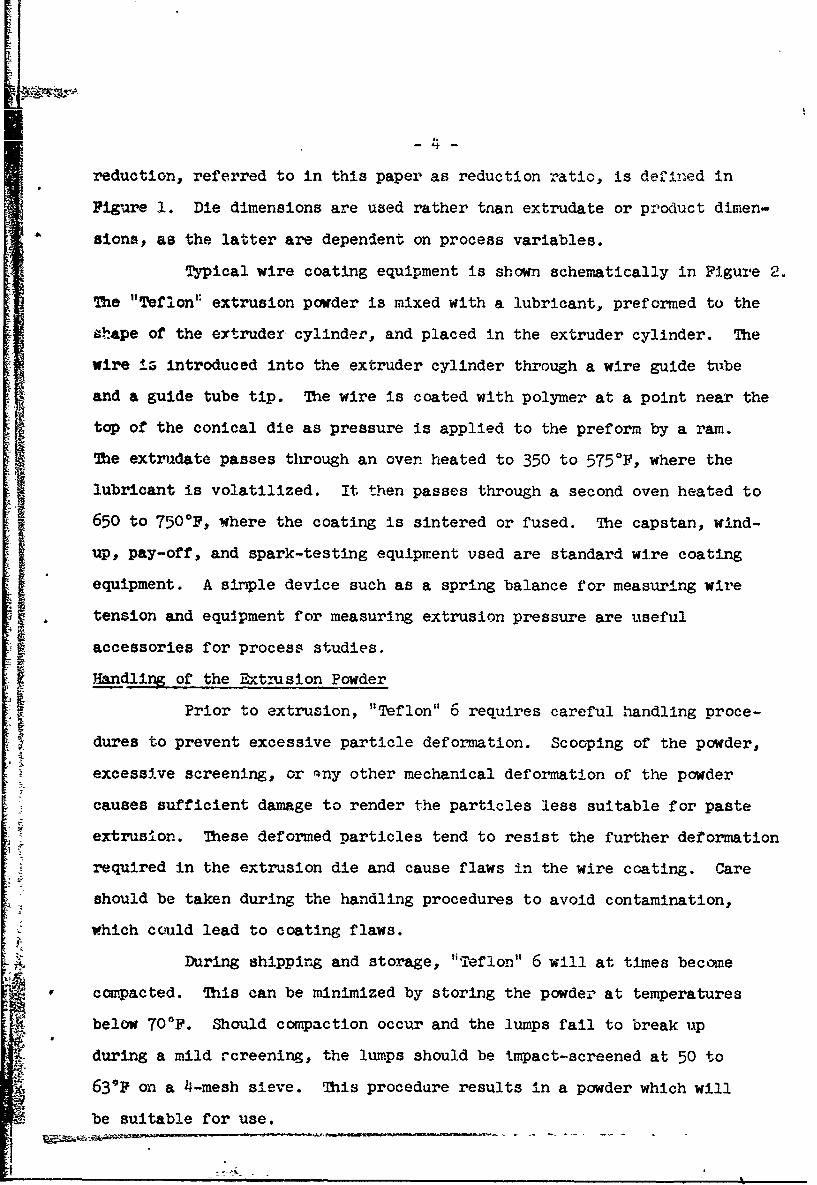
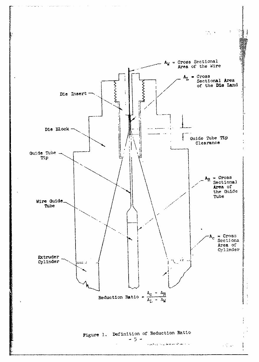
reduction, referred to in this paper as reduction ratio, is defin-ed in
Figure 1. Die dimensions are used rather than extrudate or procuct dimen-
sions, as the latter are dependent on process variables.
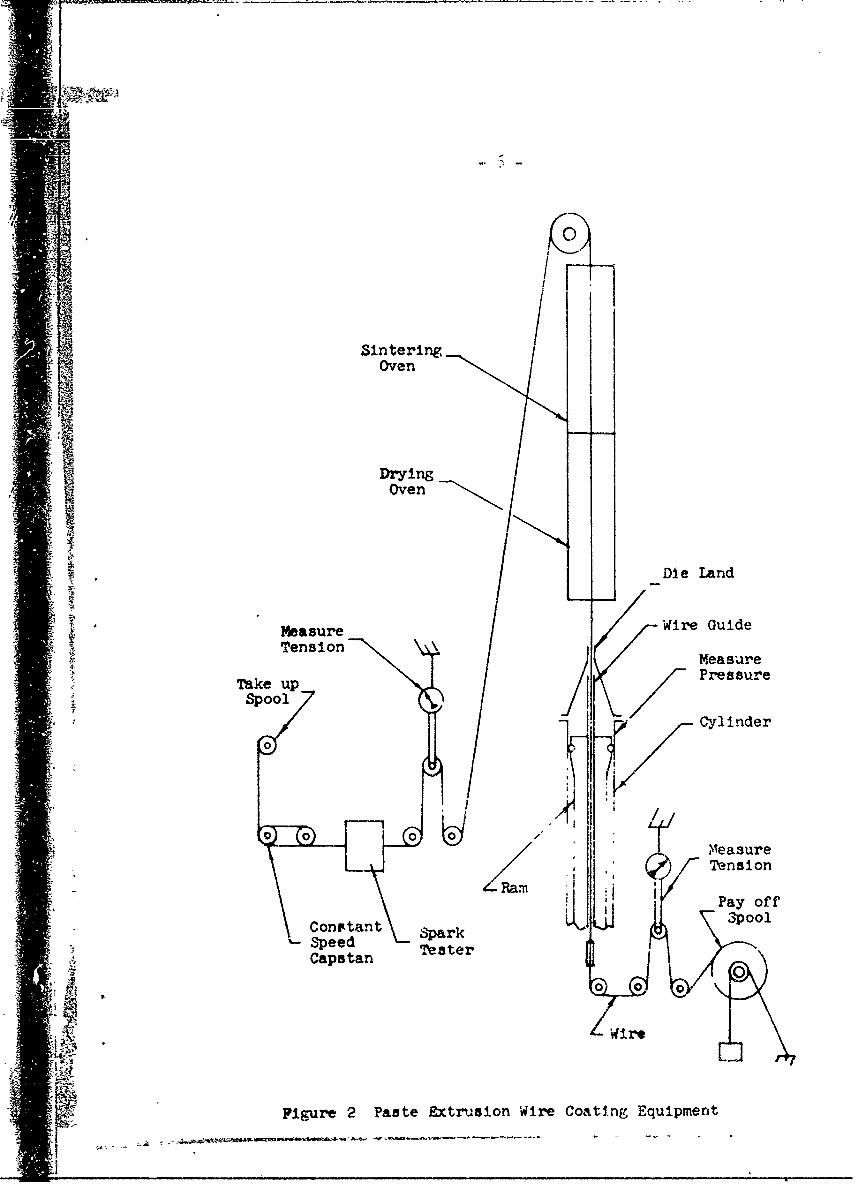
Typical wire coating equipment is shown schematically in Figure 2.
The "Teflon" extrusion powder is mixed with a lubricant, preformed to the
a'ape of the extruder cylinder, and placed in the extruder cylinder. The
wire iz introduced into the extruder cylinder through a wire guide tuibe
and a guide tube tip. The wire is coated with polymer at a point near the
top of the conical die as pressure is applied to the preform by a ram.
The extrudate passes through an oven heated to 350 to 575°F, where the
lubricant is volatilized. It then passes through a second oven heated to
650 to 750*p, where the coating is sintered or fused. The capstan, wind-
up, pay-off, and spark-testing equipm.ent used are standard wire coating
equipment. A simple device such as a spring balance for measuring wire
tension and equipment for measuring extrusion pressure are useful
accessories for process studies,
Handling of the Ext-rusion Powder
Prior to extrusion, 'Teflon" 6 requires careful handling proce-
dures to prevent excessive particle deformation. Scooping of the powder,
excessive screening, or qny other mechanical deformation of the powder
causes sufficient damage to render the particles less suitable for paste
extrusion. These deformed particles tend to resist the further deformation
required in the extrusion die and cause flaws in the wire coating. Care
should be taken during the handling procedures to avoid contamination,
which cculd lead to coating flaws.
During shipping and storage, 'iTeflon" 6 will at times become
compacted. This can be minimized by storing the powder at temperatures
below 70*F. Should compaction occur and the lumps fail to break up
during a mild screening, the lumps should be impact-screened at 50 to
63*P on a 4-mesh sieve. This procedure results in a powder which will
be suitable for use.
_ AW Cross SectionalArea of the Wire
r AL - Cross-- ,-Sectional Area
, / of the Die Land
Die Insert -- //
ii LD~ieBlc -,
Guid "'*be TipGj ~Clearance
Guide Tuvbe ,•
Tip 4 I
I _AR = Cross"I-- Sectional
/ Area of
7 the Guide
Wire Guide_ Tube
Tube K
•.• / |" ..
A Cross'p Soc.j ona
' Ar'ea of-" Cylinder
Extruder \
cylinder '
Ac - AReduction Ratio
[Figure 1. Definition of Reduction RatIO
A -- - -
Si•ri
Sintering,Oven
DryingOven
Di e Land
Measure Wire GuideTension
MeasureT•kupPressurei !•Take up_Spool
Cylinder0
,M Measure
Tension- ! •i Pay off
Con 3poolCnstant SparkSpeed TesterCaps tan
0 0
*Wire
Figure 2 Paste Extrusion Wire Coating Equipment
7I
Preparation of the Lubricated Compound
A very important step 1n preparing the powder for extrusion is
the incorporation of a lubricant. The function of the lubricant in
extrusion is to wet the polymer particles, allowing the formation of apaste which can be extruded through a die into various shapes at low
pressures. Any organic liquid which will wet "Teflon" can be used as a
lubricant provided it meets the requirements implied by the extrusion
conditions (4). VM&P grade naphthaI is recommended as a lubricant as it
is easy to incorporate into the resin, vaporizes completely and rapidly bbelow the sintering temperature (6210F) of the resin, and leaves little
or no carbon residue when vaporized. Number 30 white oil 2 is also used as
a lubricant by some processors.
The following step-wise procedure is recommended for incorporating
the lubricant. The powder should be held at 70 to 800F during this
procedure.
(1) Screen the powder as received in the shipping container through a
4-mesh sieve onto a clean, lint-free, dry sheet of paper.
(2) Transfer a predetermined weight of the screened powder to a clean,
dry container having an airtight closure. For example, a one-gallon
wide-mouth glass bottle having a metal-foil-lined closure is suitable
for a 1000 gram batch of "Teflon".
(3) Add the required amount of lubricant, naphtha, to the "Teflon" in
the container. Care should be taken here to prevent the lubricant
from wetting the walls of the container, as this hampers the mixing
action. The screw-type closure should be taped in place to prevent
any loss of lubricant. The ingredients should be weighed with a
precision of at least - 0.2%.
1 VM&P naphtha of specific gravity 0.735 to 0.749 - boiling range 194 to 3000?F.
2 White oil, "Deobase" No. 30, as supplied by L. Sonneborn Sons & Co.
-8-
(4) Shake the container briefly to minimize the wetting of the container
wall with liquid.
(5) Place the container on a pair of parallel horizontal rollers which
are driven in the same direction at 15 rpm. Allow the container to
roll for 15 to 20 minutes. Caution: Do not allow the container to
roll for extended periods of time, as this tends to work the "Teflon"
particles excessively.
(6) Remove the container from the rolls and age the compounded mixture
overnight in the sealed container at room temperature to enable the
lubricant to diffuse to the interior of individual particles and
surfaces not reached during the rolling process.
The optimum concentration of the lubricant in the compounded
mixture is dependent on the extrusion die design, the extruder cylinder
diameter, and the wall thickness of the wire Insulation applied. Normally
the lubricant comprises from 17 to 20% of the total weight of the com-
pounded mixture.
Colored wire coatings can be made by adding various pigments to
the compounded mixture. The pigments should be thermally stable at "Teflon"
processing temperatures, have a particle size not larger than that of
"Teflon" 6, and not tend to agglomerate. Pigment concentrations of 0.1 to
0.3% produce a satisfactory depth of color. The pigment is dry blended
with the "Teflon" powder prior to the addition of the lubricant.
Preparation of the Preform
The object of preforming is to.press the loose compounded mixture
of "Teflon" and the lubricant into a solid cylinder which may be charged
into the extruder cylinder. The preform is made by compacting the lubri-
cated "Teflon" mixture in a smooth-finish preform cylinder having a core
. rod in its center.
The cylinder is about three times as long as the finished preform
to allow for the volume reduction of the lubricated "Teflon". The outside
-9-
diameter of the preform is approximately 50 mils less than the diameter of J;
the extruder cylinder. The core rod diameter is about 10 mils larger than
the diameter of the wire guide tube in the extruder cylinder.
When the lubricated "Teflon" is poured into the preform cylinder
care should be taken to distribute the powder evenly around the core rod.
This insures an even compaction of powder throughout the finished preform.
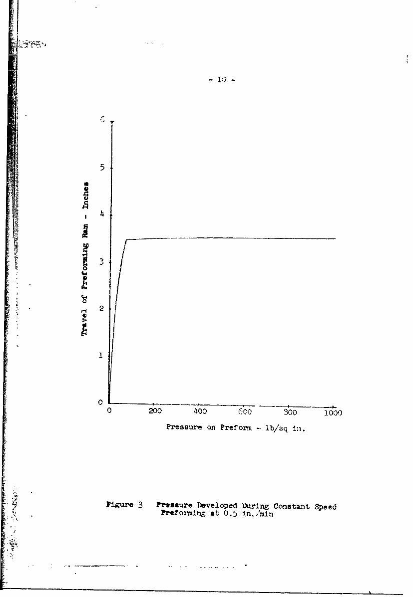
The effect of preforming pr-essure on the preform density was
determined by measuring the pressure developed on the preforming ram during
compaction of the lubricated "Teflon". Tlhe rate of travel of the preform-
ing ran was 0.5 in./min to prevent excessive shear stresses in the polymer
and to allow the entrapped air to escape. The result of this work is
illustrated graphically in Figure 3, from which it is apparent that
pressures in excess of 100 lb/sq in. do not affect preform density. In
wire-coating operations there was no difference in the extrusion perform-
ance of preforms made at 50 to 100 lb/sq in. and those made at 1000 lb/sq in.
Thus, preforming pressures of 50 to 100 lb/sq in. are sufficient for pre-
forming. In fact, higher pressures are less desirable as lubricant is
squeezed out of the preform.
The quality of the coated wire depends greatly on the preparation
and handling of the preform. Care should be taken to avoid any deformation
or contamination of the preform when removing it from the preform cylinder
and inserting it into the extruder cylinder. Finished preforms should not
be allowed to stand exposed to air before using because the lubricant
volatilizes, leaving the preforms too dry for extrusion.
The Extruder Cylinder and Ram
Various diameter cylinders are used in the extrusion of "Teflor."
for wire insulation. Normally, the diameters range from 3/4" to 2-1/2",
the smaller diameter cylinders being required for the smaller wire sizes.
The ram is driven by a screw Jack mechanism which enables a constant
thruput of material regardless of extrusion pressure. This constant thruput
-r r-~
V
0- 10 -
I0
5
S{
tS
* 4
0 200 400 60300 1000
SPressure on Preform - b/sq iM.
FFEI
:]• "" Figure P ressure Developed Durin Constant SpeedPreufor-eng at .o5 in./qmln
- rv
FI
of material is required to insure good caliper control of the extrudate.
A variable speed r shanism drives the ram. and allovT displacement speeds up
to 6 Ib/hr of lubricated "Teflon". The extruder cylinder and ram should be
able to withstand extrusion pressures of 30,000 Ib/ac in.
Reduction Ratio1
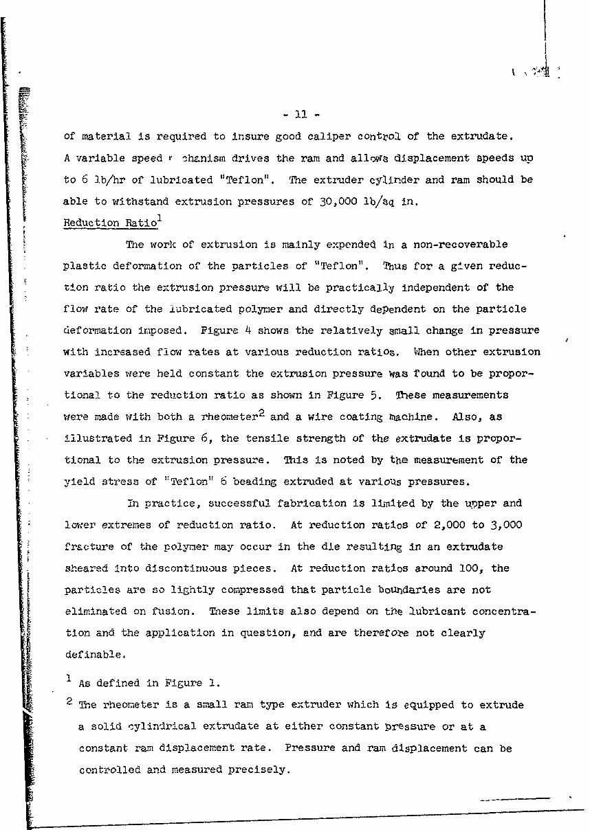
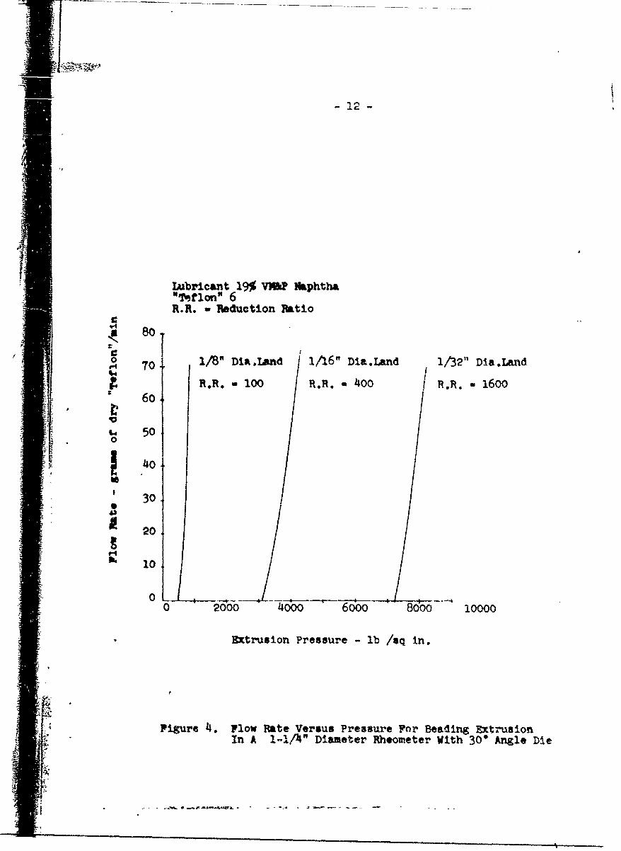
The work of extrusion is mainly expended in a non-recoverable
plastic deformation of the particles of "Teflon". Thus for a given reduc-
tion ratio the extrusion pressure will be practically independent of the
flow rate of the lubricated polymer and directly dependent on the particle
-def orriiation imposed. Figure 4 shows the relatively amall change in pressure
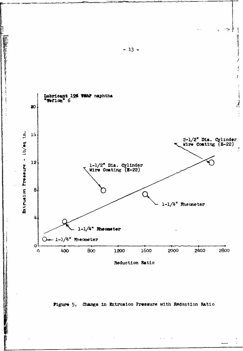
with increased flow rates at various reduction ratioa. When other extrusion
variables were held constant the extrusion pressure Was found to be propor-
tional to the reduction ratio as shown in Figure 5. These measurements
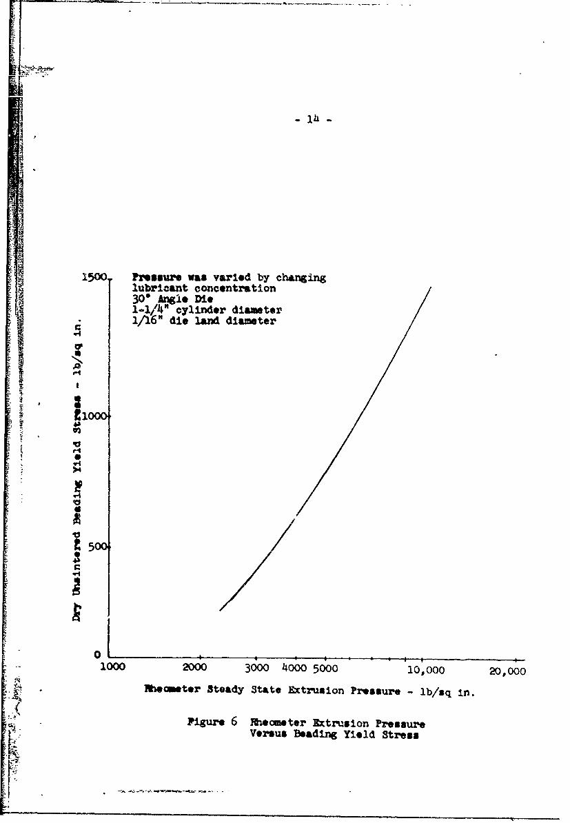
were made with both a rheometer 2 and a wire coating Pachine. Also, as
illustrated in Figure 6, the tensile strength of the extrudate is propor-
tional to the extrusion pressure. This is noted by the measurement of the
-yield stress of r:Teflon" 6 beading extruded at vario•s pressures.
in practice, successful fabrication is l-aited by the uoper and
lower extremes of reduction ratio. At reduction ratios of 2,000 to 3,000
Cracture of the polymer may occur in the die resulting in an extrudate
sheared into discontinuous pieces. At reduction ratios around 100, the
S particles are so lightly compressed that particle bourldaries are not
eliminated on fusion. These limits also depend on t1ae lubricant concentra-
tion and the application in question, and are therefore not clearly
definable.
1I As defined in Figure 1.
2 The rheometer is a small ran type extruder which Is equipped to extrude
a solid cylindrical extrudate at either constant pressure or at a
constant ram displacement rate. Pressure and ram displacement can be
controlled and measured precisely.
Lubricant 19% VN&P Naphtha"mef l on" 6R.R. - Reduction Patio
0 T 1/8" DiR.Land 1/16" Dia.Land 1/32" Dia..W~d
SR.R. 1 00 R.R.. 400 R.TA. -16oo
5,°0, 40
S 30,
• • 20
F-
04 10
0 2000 4000 6000 8000 10000
Extrusion Pressure - lb /eq In.
ii'
Figure 4. Flow Fate Versus Pressure For Beading Extrusion70In A - Diameter Rheometer With 30" Angle Die
4 R.Rm 10 R.R.400 Rj%---0
FAFF
Ii
Ulbwicant 19% VW naphthasoflt m 620
s: 16"2-1/2" Dia. Cylinder
*~Wire Coat ing 1-.22)
!I-12 1-1/2" Dia. Cylinder
J )11-1/4"" eheoeeter
4
400 800 1200 1600 2000 2400 2800
Reduction Ratio
FigUre 5. Chwise in Extrusion Pre•s•ure with Raducteon Ratio
S Pressure was varied by chmngirg
lubricant concentration] 3O Angle Die1-1/4" cylinder diameter1 1/16" die land diameter
-i III
* j
1000 2000 3000 4000 5000 10,000 20,000
Meamter Steady State Extrusion Pressure - lb/sq In.
Figure 6 Meometer Rtrxsion PressureVersus Beading Yield Stress
IL .5
F7
The Die' he function of the die used in extrusion is to convert the
rather weak lubricated preform into a strong fibrous extrudate coating on
the wire having the desired wall thiclmess. The variables affecting the
die performance are: the included angle of the die cone, the diameter of
the die land, the length of the die land, and the temperature of the die
during extrusion.
The included angle cf the die cone affects the extrusion pressure
and the smoothness of the extrudate. Die angles in excess of 60' appear
to be impractical for wire coating owing to the high extrusion pressures
developed. Die angles of less than 15u are objectionable because of the
large hold-up of material in the die taper and high cost of die fabrica-
tion. From experimental extrusion stadics we have noted a progressive
improvement in the extrudate smoothness with reduction of die angle.
The 200 included angle die is currently the most popular die,
particularly for thin-wall hook-up wire fabrication. Dies having an
included angle of 300 are also used successful?y for thicker wall insula-
tions such as coaxial cable core.
As the extrudate leaves the die land a relaxation of the elastic
strains in the extrudate occurs. This causes the outside diameter of the
* extrudate to be larger than the extrusion die land diameter. The size of
the die land diameter serves to control the amount of elastic strain
relaxation.
To estimate the die land diameter for a given wire coating
application, a knowledgje of the desired ex:trudate diameter is necessary.
The extrudate diameter required for a given product diameter is dependent
on the lubricant concentration, the crystallinity change in the pol-mer
during sintering and the conductor diameter. The extrudate diameter can
be calculated to 1 mil by using equation (1) which was derived for the
extrusion of "Teflon" 6 using -f30 white oil or VW2P naphtha as a
"iiI
-16-
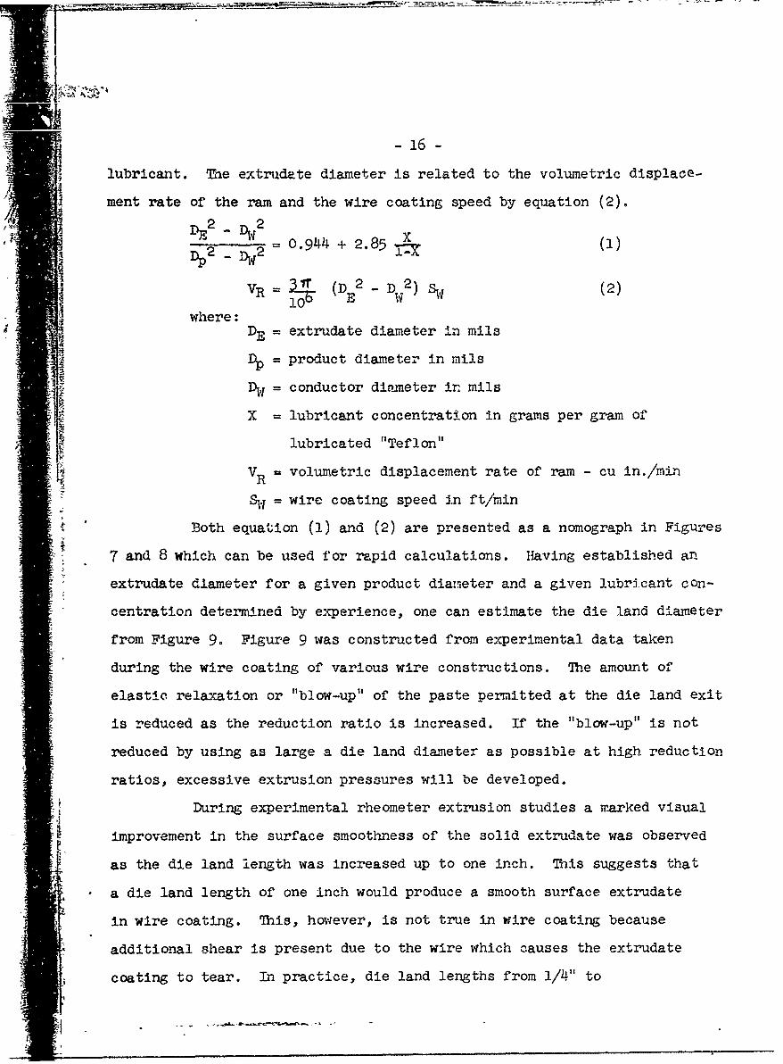
lubricant. The extrudate diameter is related to the volumetric displace-
ment rate of the ram and the wire coating speed by equation (2).
-2 0.944 + 2.85 X (1)
VR = l (DE2 - D 2 ) Sw (2)10 .7(
2
where :DE = extrudate diameter in milsDp = product diameter in mils
%f = conductor diameter in mils
X = lubricant concentration in grams per gram of
lubricated "Teflon"
SVR =volumetric displacement rate of ram - cu in./minVRS1.1 = wire coating speed in ft/min
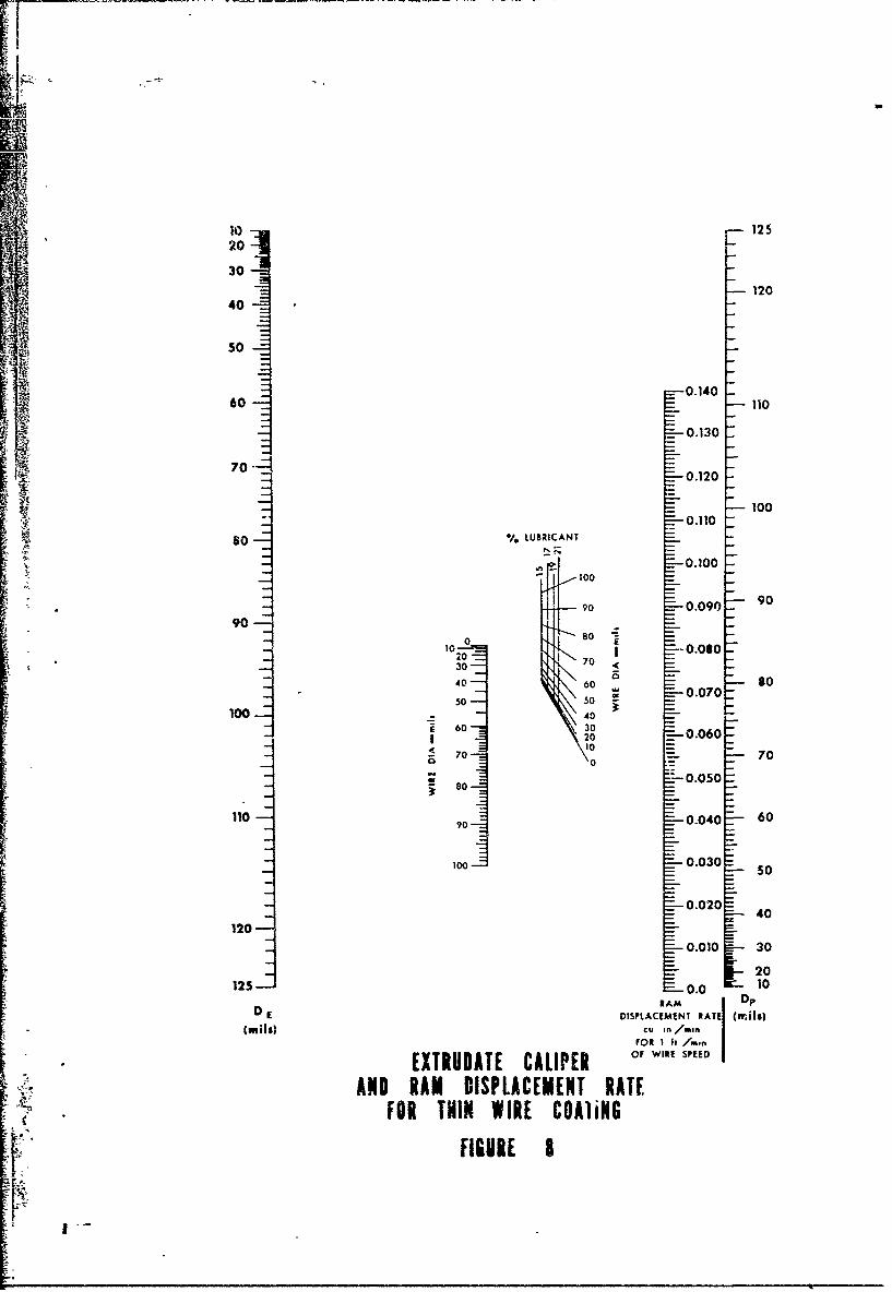
Both equation (1) and (2) are presented as a nomograph in Figures
7 and 8 which can be used for rapid calculations. Having established an
extrudate diameter for a given product diameter and a given lubricant con-
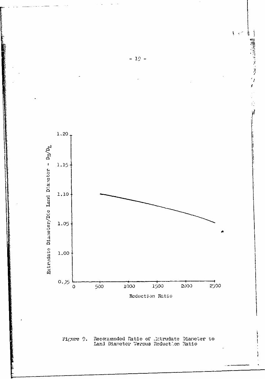
"* centration determined by experience, one can estimate the die land diameter
from Figure 9. Figure 9 was constructed from experimental data taken
during the wire coating of various wire constructions. The amount of
elastic relaxation or "blow-up" of the paste permitted at the die land exit
is reduced as the reduction ratio is increased. If the "blow-up" is not
reduced by using as large a die land diameter as possible at high reduction
ratios, excessive extrusion pressures will be developed.
During experimental rheometer extrusion studies a marked visual
improvement in the surface smoothness of the solid extrudate was observed
as the die land length was increased up to one inch. This suggests that
a die land length of one inch would produce a smooth surface extrudate
in wire coating. This, however, is not true in wire coating because
additional -shear is present due to the wire which causes the extrudate
coating to tear. In practice, die land lengths from 1/4." to
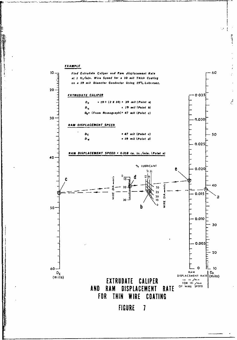
EXAMPLE
10- Find Exttudhte Celiper and Ram Jisplacement Rate -60
at I RA/Mn. Wire Speed for a 10 rail Thick C4atIng
on a 19 roil Diameter Conductor Using 19*/% Lubrvcant.
20-EXTRUDATE CALIPER 0 035
Dp =19+ (2 X 10) : 39 ail (Point a)
Dw: 19 noil (Point b)
Des (From Noznograph)O 47 miI (Point c)
30- -0.030-
RAM DISPLACEMENT SPEED
DE a 47 mail (Point c) 50Dw a 19 mil (Point d)
0.025
0 RAM DISPLACEMENT SPEED 0.0141 cu. in. /mei. (Poit ) IE 2540-
/. LUBRICANT 0 -._ •.e 0.02
C10 d
<- 20 30 -40
50 b o
" 0.01U IN-20 a o a
30
-0.005-
-- 20
60J L o L 10
(M iIS)DISPLAC•EMENT RATE ( ils)(m,)EXTRUDATE CALIPER FORfi ,/M.o
AND RAM DISPLACEMENT RATE OF WIRE SPE
FOR THIN WIRE COATING
I FIGURE 7
r
10 12520
30120
40
450
0.14060 110
0.130
70 -0.120
V.1 100
so % LUBRICANT
- 0.100
7090 0.090 9090
00 8020 7
S30 7030
40-- 60 80
s050 0 0.070
o 1__40, 60 30
220 0.0607010
-
11 0Z 70
9010 0.040 60
100 0.030 50
0.020 40
1200.010 30
20125: O0.0 10
RAM DpD E DISPLACEMENT RATE (frils)
, ,cu in,/mm iFOR I It /monn
EXTRUDATE CALIPER o,,WIR, SPEDAND RAM DISPLACEMENT RATE
FOR THIN WIRE COAliNG
FIGURE 8
I
- 1.10
1 .I0
%°11
"1"".05
1.00
rs!
0.5'0 5,00 1000 1500 2500 0 0
Rcductlion Ratio
Fimire 9.Recommu~ended I'atio of _•-:tr'adate Diame.ter toland1 Diamqeter- Versus Reduct.'.on R~atio
-20-
1 / 2 " have been found to produce an extrudate coating having the smoothest
surface possible free from tears.
The temperature of the die during extrusion should be maintained
above 75*F. Below 75*F the extrudate coating becomes rough and worthless.
This effect is believed to be associated with the room temperature transi-
tion of "Teflon'" (6). Normally die temperatures of 75 to 140"F are suf-
ficient to produce satisfactory extrudates. Added temperature has little
effect on the extrudate quality; however, it does increase the extrusion
pressure slightly. Die heating also aids the drying operation by preheating
the extrudate, which increases the rate of diffusion of the lubricant to the
coating surface where it can be vaporized..
The Guide Tube Tip
* The purpose of the guide tube and guide tube tip is to provide
a guide for the wire through the extruder cylinder to the entrance of the
die land. The clearance between the die land entrance and the guide tube
tip can be varied to control the length of wire exposed to the lubricated
polymer in the die.
When the clearance between the tip and the die land is properly
set the average velocity of the lubricated polymer in th-'s area is the same
as the wire speed. If the clearance is too large, the polymer speed is
slower than the wire speed which causes excessive shearing of the polymer
particles in contact with the wire. This shearing action increases the
wire tension enough to cause a wire failure and causes numerous coating flaws.
Should the clearance be too small, the guide tabe tip tends to plug the die,
causing high extrusion pressures. This plugging action causes surging of
the lubricated polymer around the wire, resulting in rough, discontinuous
coatings.
The guide tube tip clearance also determined how tightly the coat-
* ing adheres to the wire. In g.ýneral, the smaller the clearance, the
looser the coating on the wire. When extruding heavy wall coatings

I
-21-
(thickness greater than 15 mils) the die land diameter is usually greater
than the outside diameter of the guide tube tip. If the clearance is too
small or the guide tube tip is up in the die land it is possible to extrude '
a flow free tubing over the wire which has no adherence to the wire.
When applying thin wall insulation, the guide tube tip clearxlce
is very critical. This setting is much less critical as the wall thI06kless
of the insulation increases. Actual setting of the clearance usually
involves a trial and error procedure for each type of wire coating appllca-
tion. Typical optimum guide tube tip positions for common coating appllca- ,
tions are illustrated in Table III.
TABLE III
DATA FOR GUIDE TIP POSITIONING
CoatingWire Thickness Cylinder Reduction Tand Dia. Guide TipjM mils Dia. in. Ratio mil Clearance Limitations
milE-22 8-12 2-1/2 2510 58 13 Tension too hi1ch
if tip lower
EE-22 13-17 2-1/2 1661 68 18 Tension too hi1hif tip lower
Coax 40 2-1/2 644 100 130 Loose coating itCore tip higher
Pressure and tehslonboth low and notimportant this case.
E-22 8-12 1-1/2 978 56 25 Pressure too hiph iftip higher. Pozi-tion for min. coat-ing flaws.
Dring and SinteringThe "Teflon" extrudate as it leaves the extrusion die contains
about 19% by total weight or 40% by volume of naphtha lubricant. In the
drying oven this lubricant diffuses to the surface of the coating and is
vaporized. It is important that all the vapori.zation of the lubricant
take place on the coating surface to prevent vapor cracking. The rate ot
diffusion and vaporization is controlled by the drying oven temperature.
Drying oven temperatures generally used are about 300 0 F at the entranace i1p
- 22 -
to 575 0F at the exit.
During drying operations the oven should be exhausted sufficiently
to keep the naphtha fume concentration below 0.9%. This is to insure
adequate protection from fire.
The coating as it leaves the drying oven is very porous. The
forces of coalescence in sintering are strong enough to eliminate these
voids at the expense of a reduction in the coating diameter. A transition
temperature of 621*F must be attained for a few seconds by the coating to
effect this sintering. While the "Teflon" is. in the gel state (> 621F)
it should not be submitted to stresses. To enable the coating to be
sintered properly the sintering oven is maintained at 700 - 750 0 F.it The sintering oven should also be supplied with an exhaust
system to remove possible trace quantities of toxic fumes given off
during sintering or from coated wire left inadvertently in the hot ovens.
When using the recomnended oven temperatures, 300 to 575 0F for
drying and 700 to 750OF for sintering, approximately one-half of the total
oven length should be used for drying. The oven capacity is in most cases
the factor which limits the wire coating speed. For example, a 20 foot
oven limits the coating speed of Type E-22 wire to less than 30 ft/mmn.
The limiting coating speed of any given fabrication for a fixed oven length
can be determined by varying the coating speed until the product is
properly sintered. When the natural product has an opaque white appear-
ance it is insufficiently sintered and when it is a transparent dark brown,
or a dull grey it is over sintered. Properly sintered natural material is
slightly opalescent, almost colorless, and flexible.
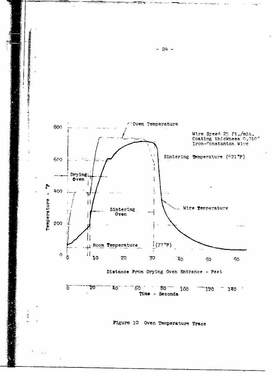
The actual temperature of the wire as it passes through the
ovens ;an be traced by coating a length of iron wire and a length of con-
stanf.,n wire.. butt joined together. This serves as a traveling
thermocouple which when connected to a potentiometer indicates the tempera-
ture of the wire under the "Teflon" coating at any oven position. The oven
temperature profile so obtained is useful in setting oven temperatures to
-23 -
obtain an efficient use of the entire oven capacity. Figure 10 illustrates
a typical trace made with a thermocouple having the same dimensions as
Type E-22 hook-up wire. aa
Drying and sintering rates can at times be increased by increasing
oven temperatures. Temperatures in excess of those recommended for the dry-
ing ovens often cause flaws in "Teflon" coating. Higher temperatures in the
sintering ovens can be used provided the coating temperature does not exceed
720°F. Above 720*F degradation of the "Teflon" coating begins to take place.
Typical ovens used commercially consist of long metal pipes 1" or
2" in diameter which are heated by electrical coils, strip or band heaters.
The wall temperatures of these ovens should be controlled and measured to
+ 1OF at intervals along the oven length.
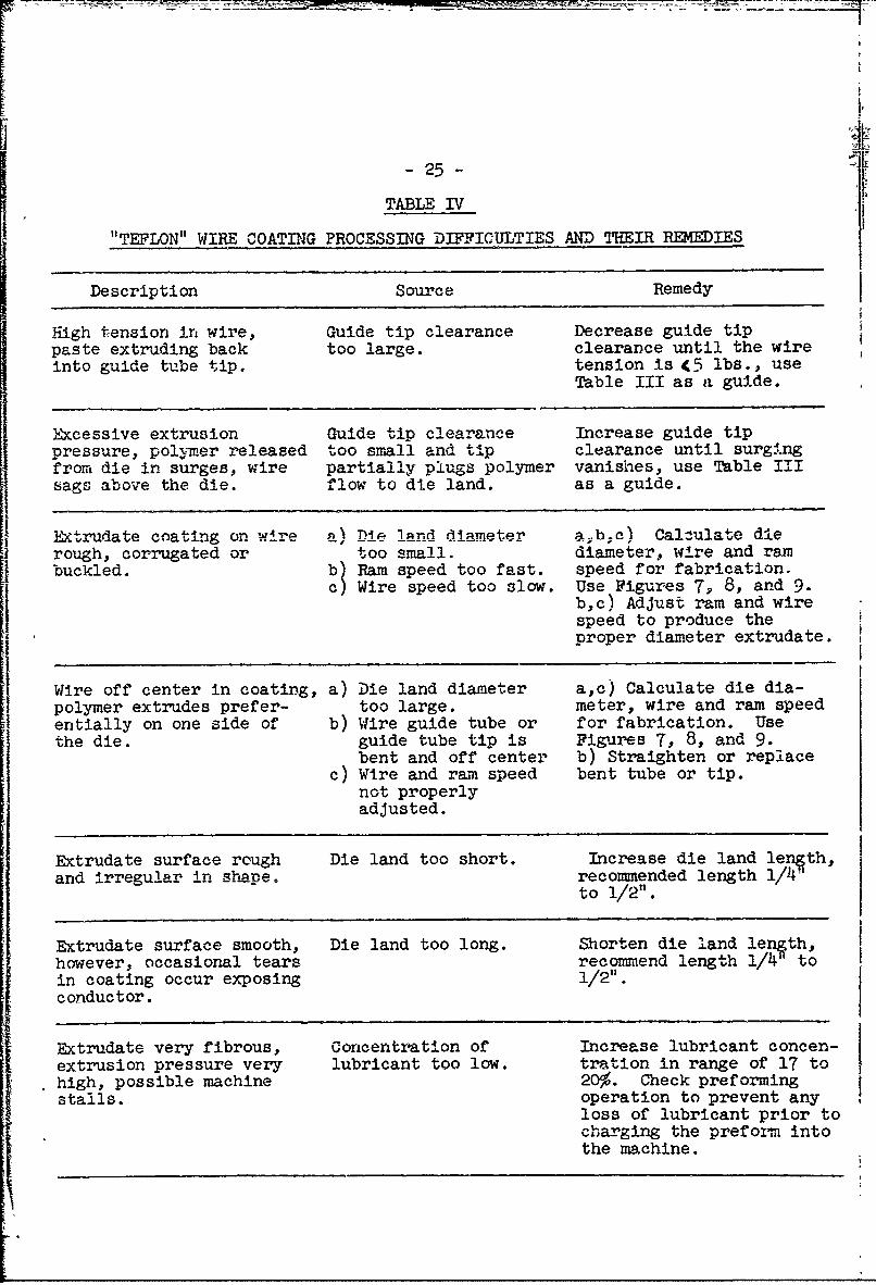
During the experimental wire coating process studies a number of
processing difficulties were noted which can be remedied quite easily.
Table IV summarizes our experience in "trouble shooting" the wire coating
process.
summa -
The purpose of Guw-study of "Teflon" 6 extrusion, sometimes re-
ferred to as paste extrusion, for insulating wire with "Teflon" was to
determine the effect of each of the operating variables on the quality of the
wire insulation. The die design, guide tip clearance, and the oven tempera-
tures were found to be the most critical variables. For optimum machine
performance the ram displacement rat- and the wire speed should be controlled
as accurately as possible.
The extrusion process in its present stage of development is
a suitable means for the coimmercial production of wire insulated with "Teflon'
it enables the use of the excellent properties of the "Teflon" insulated
wire in many commercial applications.
i51.I 24-
8r- Oven TemperatureI /Wire S-eed 21:, ft.!ml~n.
Coating th~ckness r,..nlc
Iron-ronstantan W -1e
Sliftering Teperature (•.1F)
00
i '" •4oo _ /!
SSinterin Wire Temperature
S200
. _ Room Temperature_• (77"F)
010 20 30 -0o
Distance Prom Drying Oven Entrance - Feet
Tird*e - Seconds
Figure 1.0 Oven Temperature. Trace
-25
TABLE IV
"TEFLON" WIRE COATING PROCESSING DIFFICULTIES AND THEIR REMEDIES
Description Source Remedy
High tension in wire, Guide tip clearance Decrease guide tippaste extruding back too large. clearance until the wireinto guide tube tip. tension is <5 lbs., use
Table III as a guide.
Excessive extrusion Guide tip clearance Increase guide tippressure, polymer released too small and ti-p clearance until surgingfrom die in surges, wire partially plugs polymer vanishes, use Table IIIsags above the die. flow to die land. as a guide.
Extrudate coating on wire al Die lad -diameter a•be) Calculate die
rough, corrugated or too small. diameter, wire and rambuckled. b) Ram speed too fast. speed for fabrication.
c) Wire speed too slow. Use Figures 7, 8, and 9.b,c) Adjust ram and wirespeed to produce theproper diameter extrudate.
Wire off center in coating, a) Die land diameter a,c) Calculate die dia-polymer extrudes prefer- too large. meter, wire and ram speedentially on one side of b) Wire guide tube or for fabrication. Usethe die. guide tube tip is Figures 7., 8, and 9.
bent and off center b) Straighten or replacec) Wire and ram speed bent tube or tip.
not properlyadjusted.
Extrudate surface rough Die land too short. Increase die land length,and irregular in sha½pe. recommended length 1/Pt'
to 1/2".
Extrudate surface smooth, Die land too long. Shorten die land length,however, occasional tears recommend length 1/41 toin coating occur exposing 1/2".conductor.
Extrudate very fibrous, Concentration of Increase lubricant concen-extrusion pressure very lubricant too low. tration in range of 17 tohigh, possible machine 20%. Check preformingstalls. operation to prevent any
loss of lubricant prior tocharging the preform intothe machine.
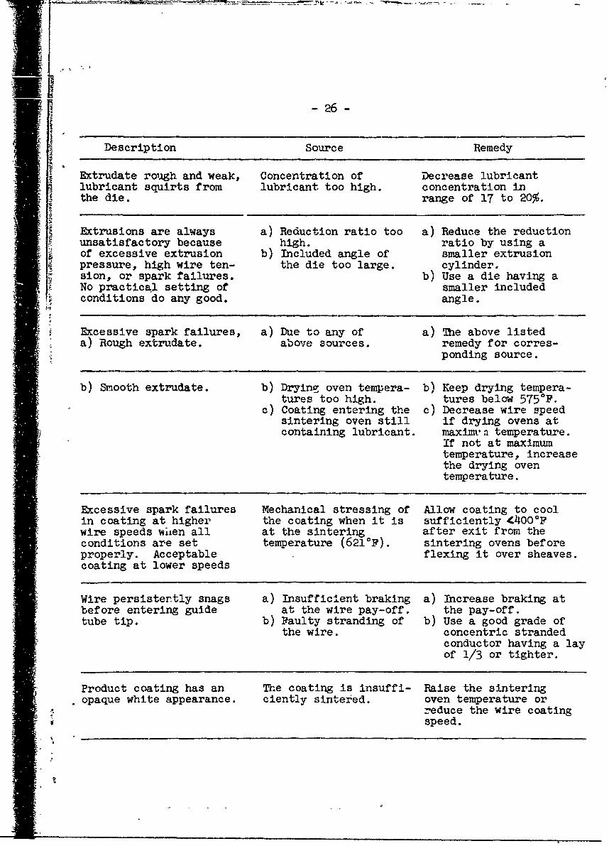
-26-
Description Source Remedy
Extrudate rough and weak, Concentration of Decrease lubricantlubricant squirts from lubricant too high. concentration inthe die. range of 17 to 20%.
Extrusions are always a) Reduction ratio too a) Reduce the reductionunsatisfactory because high. ratio by using aof excessive extrusion b) Included angle of smaller extrusionpressure, high wire ten- the die too large. cylinder,sion, or spark failures. b) Use a die having aNo practical setting of smaller includedconditions do any good. angle.
Excessive spark failures, a) Due to any of a) The above listed*a) Rough extrudate. above sources, remedy for corres-
ponding source.
b) Smooth extrudate. b) Drying oven tempera- b) Keep drying tempera-tures too high. tures below 575*F.
c) Coating entering the c) Decrease wire speedsintering oven still if drying ovens atcontaining lubricant. maximr'n temperature.
If not at maximumtemperature, increasethe drying oventemperature.
Excessive spark failures Mechanical stressing of Allow coating to coolin coating at higher the coating when it is sufficiently 4400*Fwire speeds w'ien all at the sintering after exit from theconditions are set temperature (621 0 F). sintering ovens beforeproperly. Acceptable flexing it over sheaves.coating at lower speeds
Wire persistertly snags a) Insufficient braking a) Increase braking atbefore entering guide at the wire pay-off. the pay-off.tube tip. b) Faulty stranding of b) Use a good grade of
the wire. concentric strandedconductor having a layof 1/3 or tighter.
Product coating has an The coating is insuffi- Raise the sinteringopaque white appearance. ciently sintered. oven temperature or
speeduce the wire coatingS~speed.
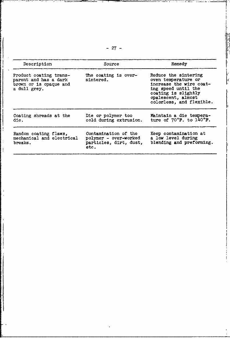
-27-
Description Source Remedy
Product coating trans- The coating is over- Reduce the sinteringparent and has a dark sintered. oven temperature orbrown or is opaque and increase the wire coat-a dull grey. ing speed until the
coating is slightlyopalescent, almcstcolorless, and flexible.
Coating shreads at the Die or polymer too Yintain a die tempera-die. cold during extrusion. ture of 70*F. to 140*F.
Random coating flaws, Contamination of the Keep contamination atmechanical and electrical polymer - over-worked a low level duringbreaks. particles, dirt, dust, blending and preforming.
etc.
1! - 28 -
References
(1) R. C. Doban, C. A. Sperati, and B. W. Sandt - "The Physical
Properties of 'Teflon' Polytetrafluoroethylene". The Society of
Plastics Engineers Journal, Vol. 11, Number 9, November 1955.
(2) B. E. Ely, Jr. - "Applications of 'Teflon' Tetrafluoroethylene
Resin in the Electrical Industry". Presented before the Winter
meeting of the AIEE, January 21, 22, 1953.
(3) J. J. Ondrejcin - "Wire Insulated with 'Teflon' Tetrafluoroethylene
- Resin for High Temperature Uses'. Wire and Wire Products, July, 1955.
(4) E. E. Lewis and C. M. Winchester - "The Rheology of Lubricated
Polytetrafluoroethylene Compositions". ind. Eng. Chem. i_,
pp. 1123-1127, May 1953.
(5) W. B. Thompson, Jr. and R. E. Stabler - "Paste Extrusion",
Modern Plastics, February 1956.
(6) C. E. Weir, "Transitions and Phases of Polytetrafluoroethylene
'Teflon'", J. Research Natl. Bur. Standards 50, 95 (1953).
- ,