Embed Size (px)
Citation preview
1
Akos Kriston, Andreas Pfrang, Vanesa Ruiz,
Ibtissam Adanouj, Franco Di Persio,
Marek Bielewski, Emilio Napolitano, Lois Brett
January 2019
Progress on thermal propagation testing
The European Commission’s
science and knowledge service
Joint Research Centre
2
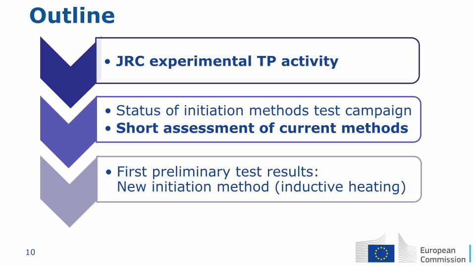
Outline
• JRC experimental TP activity
• Status of initiation methods test campaign
• Short assessment of current methods
• First preliminary test results: New initiation method (inductive heating)
3
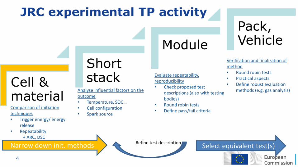
Cell & material
Short stack
Module
Pack, Vehicle
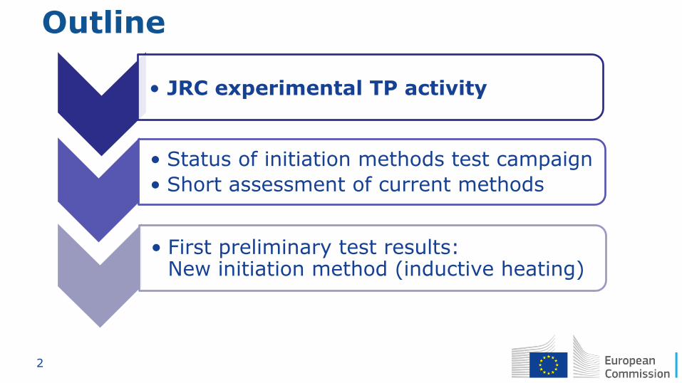
Comparison of initiation techniques • Trigger energy/ energy
release • Repeatability + ARC, DSC
Analyse influential factors on the outcome • Temperature, SOC… • Cell configuration • Spark source
Evaluate repeatability, reproducibility • Check proposed test
descriptions (also with testing bodies)
• Round robin tests • Define pass/fail criteria
Verification and finalization of method • Round robin tests • Practical aspects • Define robust evaluation
methods (e.g. gas analysis)
Refine test description Narrow down init. methods Select equivalent test(s)
JRC experimental TP activity
4
Cell & material
Short stack
Module
Pack, Vehicle
Comparison of initiation techniques • Trigger energy/ energy
release • Repeatability + ARC, DSC
Analyse influential factors on the outcome • Temperature, SOC… • Cell configuration • Spark source
Evaluate repeatability, reproducibility • Check proposed test
descriptions (also with testing bodies)
• Round robin tests • Define pass/fail criteria
Verification and finalization of method • Round robin tests • Practical aspects • Define robust evaluation
methods (e.g. gas analysis)
Refine test description Narrow down init. methods Select equivalent test(s)
JRC experimental TP activity
5
Outline
• JRC experimental TP activity
•Status of initiation methods test campaign
•Short assessment of current methods
•First preliminary test results: New initiation method (inductive heating)
6
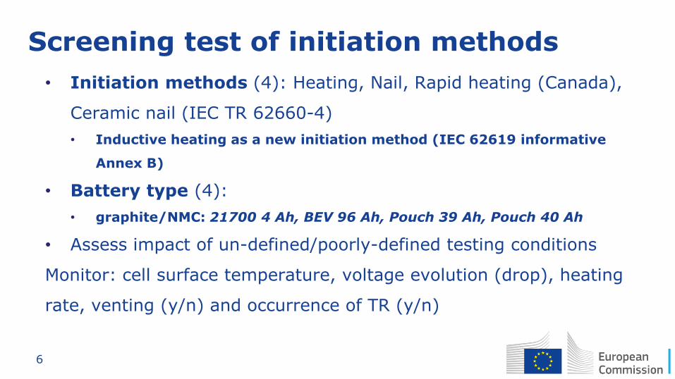
Screening test of initiation methods
• Initiation methods (4): Heating, Nail, Rapid heating (Canada),
Ceramic nail (IEC TR 62660-4)
• Inductive heating as a new initiation method (IEC 62619 informative
Annex B)
• Battery type (4):
• graphite/NMC: 21700 4 Ah, BEV 96 Ah, Pouch 39 Ah, Pouch 40 Ah
• Assess impact of un-defined/poorly-defined testing conditions
Monitor: cell surface temperature, voltage evolution (drop), heating
rate, venting (y/n) and occurrence of TR (y/n)
7
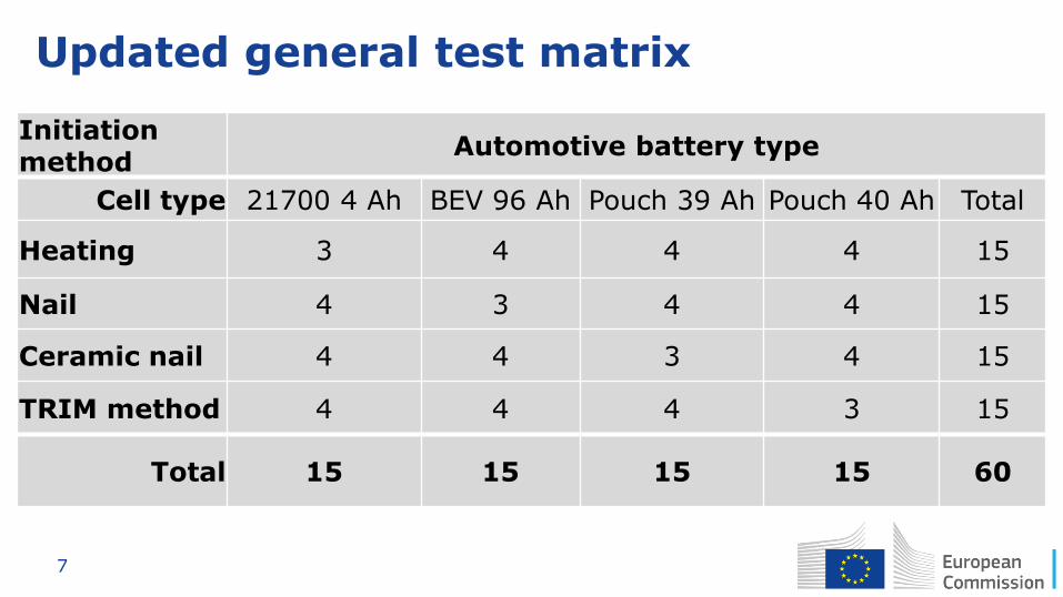
Updated general test matrix
Initiation method
Automotive battery type
Cell type 21700 4 Ah BEV 96 Ah Pouch 39 Ah Pouch 40 Ah Total
Heating 3 4 4 4 15
Nail 4 3 4 4 15
Ceramic nail 4 4 3 4 15
TRIM method 4 4 4 3 15
Total 15 15 15 15 60
8
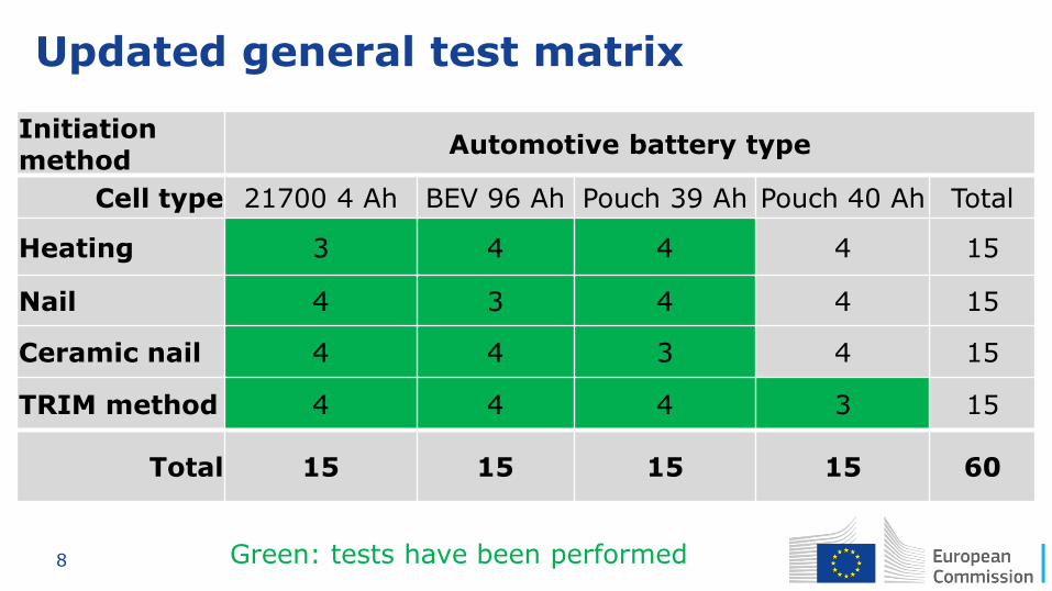
Updated general test matrix
Green: tests have been performed
Initiation method
Automotive battery type
Cell type 21700 4 Ah BEV 96 Ah Pouch 39 Ah Pouch 40 Ah Total
Heating 3 4 4 4 15
Nail 4 3 4 4 15
Ceramic nail 4 4 3 4 15
TRIM method 4 4 4 3 15
Total 15 15 15 15 60
9
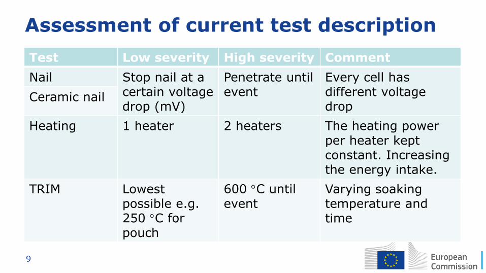
Assessment of current test description
Test Low severity High severity Comment
Nail Stop nail at a certain voltage drop (mV)
Penetrate until event
Every cell has different voltage drop
Ceramic nail
Heating 1 heater 2 heaters The heating power per heater kept constant. Increasing the energy intake.
TRIM Lowest possible e.g. 250 C for pouch
600 C until event
Varying soaking temperature and time
10
Outline
• JRC experimental TP activity
• Status of initiation methods test campaign
• Short assessment of current methods
• First preliminary test results: New initiation method (inductive heating)
11
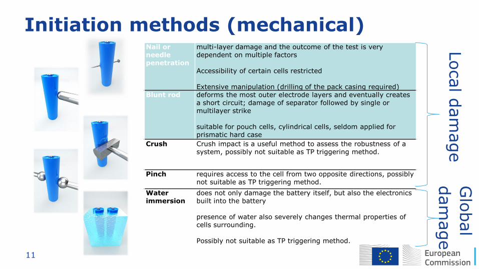
Initiation methods (mechanical) Nail or needle penetration
multi-layer damage and the outcome of the test is very dependent on multiple factors
Accessibility of certain cells restricted
Extensive manipulation (drilling of the pack casing required) Blunt rod deforms the most outer electrode layers and eventually creates
a short circuit; damage of separator followed by single or multilayer strike
suitable for pouch cells, cylindrical cells, seldom applied for prismatic hard case
Crush Crush impact is a useful method to assess the robustness of a system, possibly not suitable as TP triggering method.
Pinch requires access to the cell from two opposite directions, possibly not suitable as TP triggering method.
Water immersion
does not only damage the battery itself, but also the electronics built into the battery
presence of water also severely changes thermal properties of cells surrounding.
Possibly not suitable as TP triggering method.
Local d
am
age
Glo
bal
dam
age
12
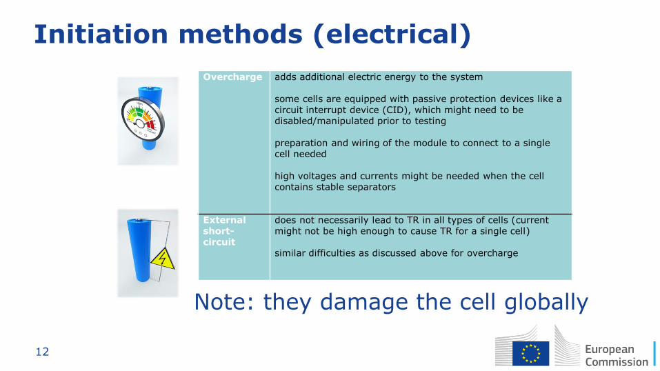
Initiation methods (electrical)
Overcharge adds additional electric energy to the system
some cells are equipped with passive protection devices like a circuit interrupt device (CID), which might need to be disabled/manipulated prior to testing
preparation and wiring of the module to connect to a single cell needed
high voltages and currents might be needed when the cell contains stable separators
External short-circuit
does not necessarily lead to TR in all types of cells (current might not be high enough to cause TR for a single cell)
similar difficulties as discussed above for overcharge
Note: they damage the cell globally
13
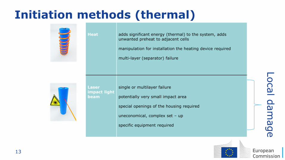
Initiation methods (thermal)
Heat
adds significant energy (thermal) to the system, adds unwanted preheat to adjacent cells
manipulation for installation the heating device required
multi-layer (separator) failure
Laser impact light beam
single or multilayer failure
potentially very small impact area
special openings of the housing required
uneconomical, complex set – up
specific equipment required
Local d
am
age
14
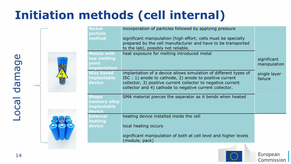
Initiation methods (cell internal) Nickel particle method
incorporation of particles followed by applying pressure
significant manipulation (high effort; cells must be specially prepared by the cell manufacturer and have to be transported to the lab), possibly not reliable.
Metals with low melting point implantation
heat exposure for melting introduced metal
Wax based implantable device
implantation of a device allows simulation of different types of ISC : 1) anode to cathode, 2) anode to positive current collector, 3) positive current collector to negative current collector and 4) cathode to negative current collector.
Shape memory alloy implantable device
SMA material pierces the separator as it bends when heated
Internal heating device
heating device installed inside the cell
local heating occurs
significant manipulation of both at cell level and higher levels (module, pack)
significant manipulation
single layer failure
Local dam
age
15
Ideal initiation method
Goal: Imitate realistic internal short circuit and simulate the
dynamics of internal and external failures
Properties:
• Damaging the separator locally
• No major damage to the cell case
• Controllable and minimal energy input to avoid overheating
of adjacent cells and unwanted side reactions
• Minimal manipulation at pack level (manipulation is needed,
though)
16
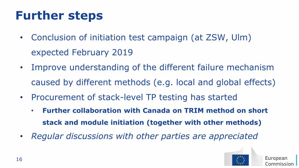
Further steps
• Conclusion of initiation test campaign (at ZSW, Ulm)
expected February 2019
• Improve understanding of the different failure mechanism
caused by different methods (e.g. local and global effects)
• Procurement of stack-level TP testing has started
• Further collaboration with Canada on TRIM method on short
stack and module initiation (together with other methods)
• Regular discussions with other parties are appreciated
17
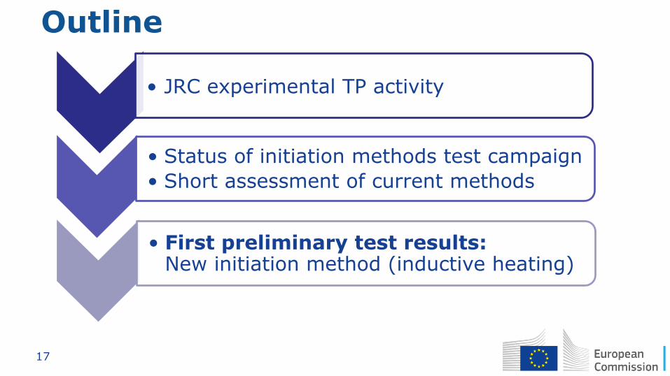
Outline
• JRC experimental TP activity
• Status of initiation methods test campaign
• Short assessment of current methods
• First preliminary test results: New initiation method (inductive heating)
18
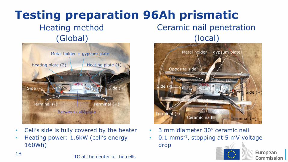
Testing preparation 96Ah prismatic
• Cell’s side is fully covered by the heater
• Heating power: 1.6kW (cell’s energy
160Wh)
Heating plate (1) Heating plate (2)
Side (+) Side (-)
Terminal (+) Terminal (-)
Opposite side
Metal holder + gypsum plate
Side (+)
Side (-)
Terminal (+)
Terminal (-) Ceramic nail
Metal holder + gypsum plate
Heating method
(Global)
Ceramic nail penetration
(local)
• 3 mm diameter 30 ceramic nail
• 0.1 mms-1, stopping at 5 mV voltage
drop
Between cell&plate
TC at the center of the cells
19
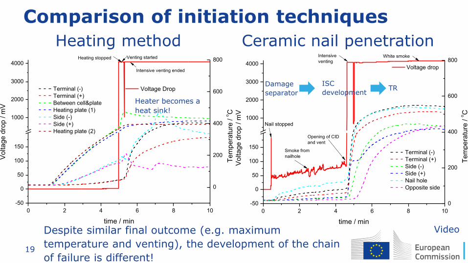
Comparison of initiation techniques
Video
0 2 4 6 8 10
-50
0
50
100
150
1000
2000
3000
4000
White smoke
Vo
lta
ge
dro
p / m
V
time / min
Voltage drop
Nail stopped
Smoke from
nailhole
Opening of CID
and vent
Intensive
venting
0
200
400
600
800
Te
mp
era
ture
/ o
C
Terminal (-)
Terminal (+)
Side (-)
Side (+)
Nail hole
Opposite side
Heating method Ceramic nail penetration
ISC
development TR
Damage
separator Heater becomes a
heat sink!
0 2 4 6 8 10
-50
0
50
100
150
1000
2000
3000
4000
Vo
lta
ge
dro
p / m
V
time / min
Voltage Drop
0
200
400
600
800
Te
mp
era
ture
/ o
C
Intensive venting ended
Venting started
Terminal (-)
Terminal (+)
Between cell&plate
Heating plate (1)
Side (-)
Side (+)
Heating plate (2)
Heating stopped
Despite similar final outcome (e.g. maximum
temperature and venting), the development of the chain
of failure is different!
20
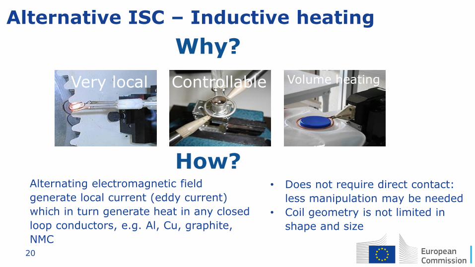
Alternative ISC – Inductive heating
Why?
Very local Controllable Volume heating
Alternating electromagnetic field
generate local current (eddy current)
which in turn generate heat in any closed
loop conductors, e.g. Al, Cu, graphite,
NMC
How? • Does not require direct contact:
less manipulation may be needed
• Coil geometry is not limited in
shape and size
21
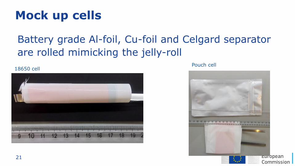
Mock up cells
Battery grade Al-foil, Cu-foil and Celgard separator
are rolled mimicking the jelly-roll
18650 cell Pouch cell
22
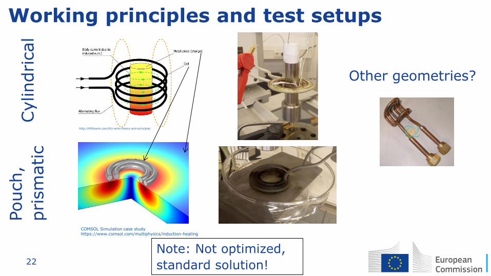
Working principles and test setups
COMSOL Simulation case study https://www.comsol.com/multiphysics/induction-heating
http://hflitzwire.com/litz-wire-theory-and-principle/
Note: Not optimized,
standard solution!
Cylindrical
Pouch,
prism
atic
Other geometries?
23
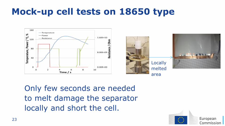
Mock-up cell tests on 18650 type
Only few seconds are needed
to melt damage the separator
locally and short the cell.
Locally
melted
area
24
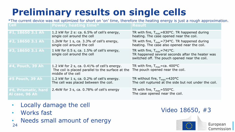
Preliminary results on single cells
• Locally damage the cell
• Works fast
• Needs small amount of energy
Cell Power, heating time* Result
#1, 18650 3.1 Ah 1.2 kW for 2 s: ca. 6.5% of cell’s energy, single coil around the cell
TR with fire, Tmax=830°C. TR happened during heating. The case opened near the coil.
#2, 18650 3.1 Ah 1.2kW for 1 s, ca. 3.3% of cell’s energy, single coil around the cell
TR with fire, Tmax=734°C. TR happened during heating. The case also opened near the coil.
#3, 18650 3.1 Ah 1 kW for 0.5 s, ca. 1.5% of cell’s energy, single coil around the cell
TR with fire, Tmax=741°C. TR happened several seconds after the heater was switched off. The pouch opened near the coil.
#4, Pouch, 39 Ah 1.2 kW for 2 s, ca. 0.41% of cell’s energy. The coil is placed parallel to the surface at the middle of the cell
TR with fire, Tmax=ca. 400°C The pouch opened near the coil.
#5 Pouch, 39 Ah 1.2 kW for 1 s, ca. 0.2% of cell’s energy. The cell was placed between the coil.
TR without fire, Tmax=420°C The cell ruptured at the side but not under the coil.
#6, Prismatic, hard Al case, 96 Ah
2.4kW for 3 s, ca. 0.78% of cell’s energy TR with fire, Tmax=550°C. The case opened near the coil.
Video 18650, #3
*The current device was not optimized for short on ‘on’ time, therefore the heating energy is just a rough approximation.
25
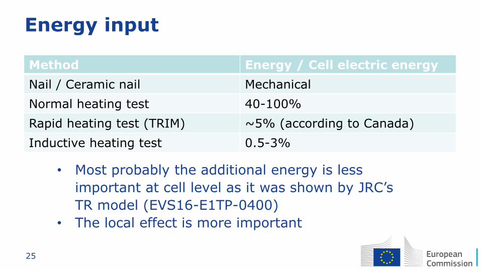
Energy input
Method Energy / Cell electric energy
Nail / Ceramic nail Mechanical
Normal heating test 40-100%
Rapid heating test (TRIM) ~5% (according to Canada)
Inductive heating test 0.5-3%
• Most probably the additional energy is less
important at cell level as it was shown by JRC’s
TR model (EVS16-E1TP-0400)
• The local effect is more important
26
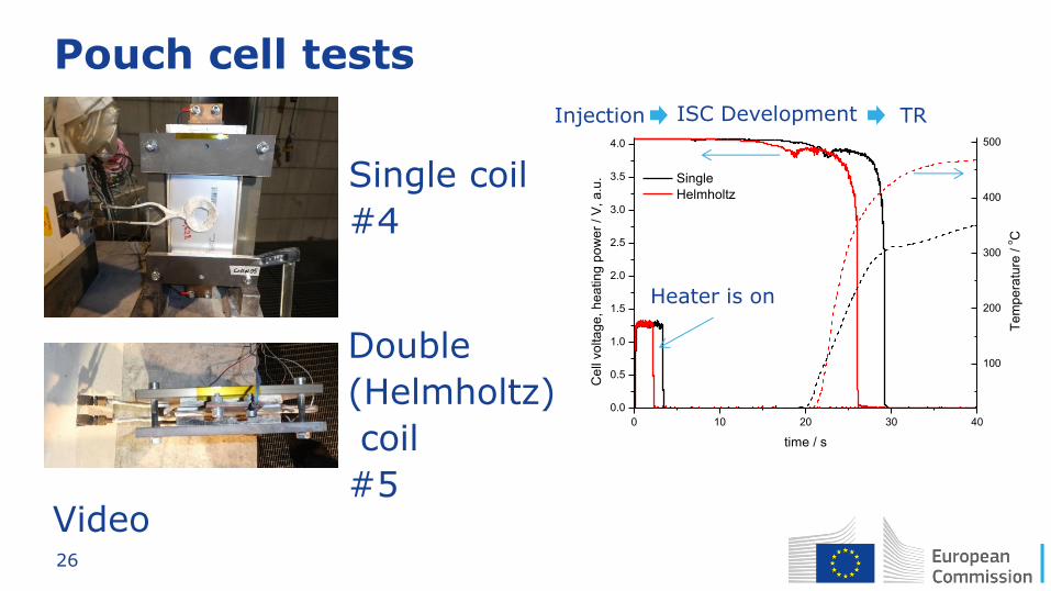
Pouch cell tests
Video
0 10 20 30 40
0.0
0.5
1.0
1.5
2.0
2.5
3.0
3.5
4.0
Single
Helmholtz
Ce
ll vo
lta
ge
, h
ea
tin
g p
ow
er
/ V
, a
.u.
time / s
100
200
300
400
500
Te
mp
era
ture
/ o
C
Single coil
#4
Double
(Helmholtz)
coil
#5
Injection ISC Development TR
Heater is on
27
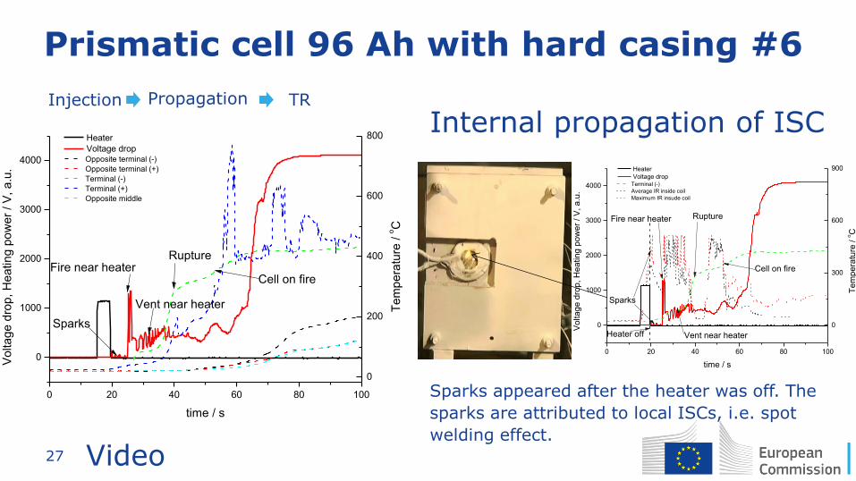
Prismatic cell 96 Ah with hard casing #6
Injection Propagation TR
Internal propagation of ISC
Video
0 20 40 60 80 100
0
1000
2000
3000
4000
Vo
lta
ge
dro
p, H
ea
tin
g p
ow
er
/ V
, a
.u.
time / s
Heater
Voltage drop
Fire near heater
Sparks
Vent near heater
Rupture
Cell on fire
0
200
400
600
800
Opposite terminal (-)
Opposite terminal (+)
Terminal (-)
Terminal (+)
Opposite middle
Te
mp
era
ture
/ o
C
0 20 40 60 80 100
0
1000
2000
3000
4000
Vo
lta
ge
dro
p, H
ea
tin
g p
ow
er
/ V
, a
.u.
time / s
Heater
Voltage drop
Fire near heater
Sparks
Vent near heater
Rupture
Cell on fire
Heater off0
300
600
900
Terminal (-)
Average IR inside coil
Maximum IR insude coil
Te
mp
era
ture
/ o
C
Sparks appeared after the heater was off. The
sparks are attributed to local ISCs, i.e. spot
welding effect.
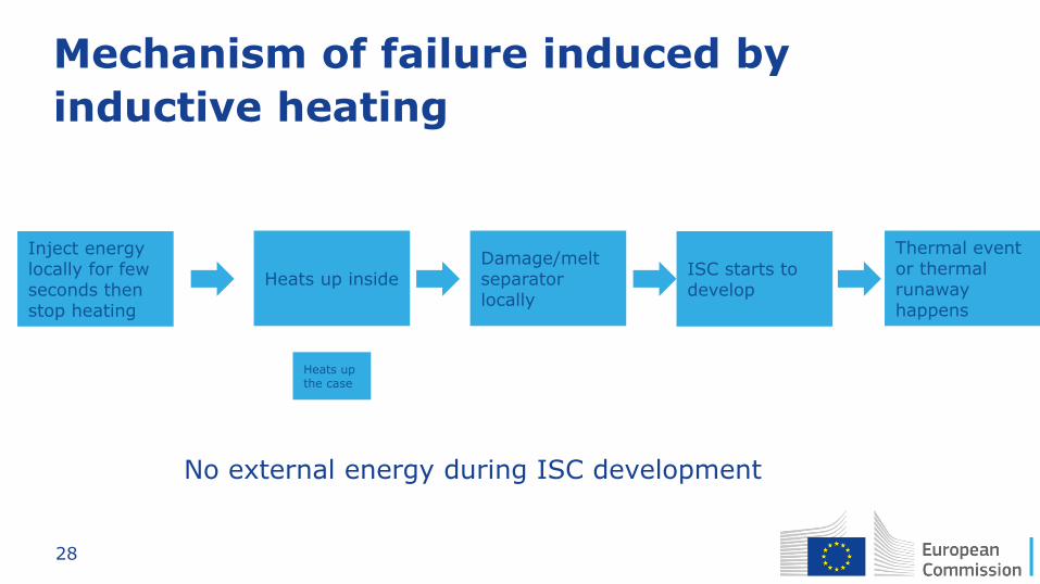
28
Mechanism of failure induced by
inductive heating
Inject energy locally for few seconds then stop heating
Heats up the case
Heats up inside Damage/melt separator locally
ISC starts to develop
Thermal event or thermal runaway happens
No external energy during ISC development
29
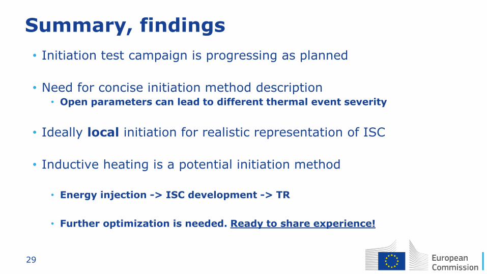
Summary, findings
• Initiation test campaign is progressing as planned
• Need for concise initiation method description • Open parameters can lead to different thermal event severity
• Ideally local initiation for realistic representation of ISC
• Inductive heating is a potential initiation method
• Energy injection -> ISC development -> TR
• Further optimization is needed. Ready to share experience!
30
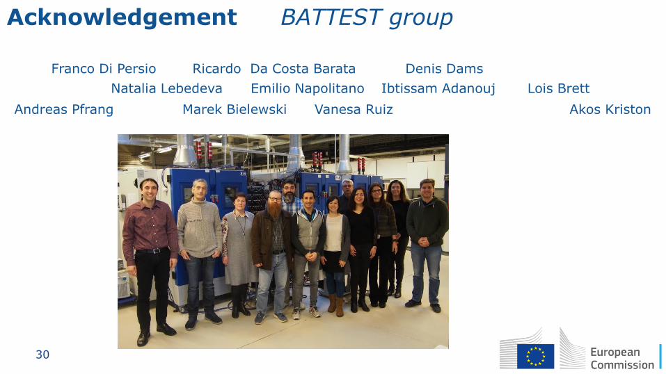
Acknowledgement • BATTEST group
Akos Kriston
Franco Di Persio
Natalia Lebedeva
Vanesa Ruiz Andreas Pfrang
Denis Dams
Ibtissam Adanouj Lois Brett
Marek Bielewski
Emilio Napolitano
Ricardo Da Costa Barata
31
•EU Science Hub: ec.europa.eu/jrc
•Twitter: @EU_ScienceHub
•Facebook: EU Science Hub - Joint Research Centre
•LinkedIn: Joint Research Centre
•YouTube: EU Science Hub
Stay in touch