Embed Size (px)
Citation preview

THE ELECTRIC SUPER SPORTS CAR SLS AMG ELECTRIC DRIVEWith the SLS AMG Electric Drive, Mercedes-AMG sets new standards not only in electric mobility.
With 552 kW (750 PS) and 1000 Nm it is the most powerful Mercedes-Benz produced
in series and also the fastest electric series vehicle in the world. The all-wheel drive enables
single-wheel torque vectoring and offers a high drive dynamic agility.
COVER STORY ELEcTroMoBiLiTy

MOTIVATION BEHIND THE BATTERY ELECTRIC DRIVETRAIN
In 2009, Mercedes-AMG created the suc-cessor to the legendary gullwing door vehicle with the SLS AMG. Amongst other things, the 420 kW of the 6.3-l-V8 front middle engine combined with the transaxle drive with seven speed double coupling drive enable driving perfor-mance from 0 to 100 km/h in 3.8 s.
The aim was to develop an electric super sports car as an alternative drive variant which should rival the perfor-mance of the pure combustion model as closely as possible.
If competing systems such as pure fuel alternatives, hybrid drives, battery and fuel cell powered electric vehicle are compared, a clear optimum be tween the power to weight ratio of the components, possible performance data at vehicle level, emission advantages and develop-ment and manufacturing costs of battery powered drives should be highlighted. A performance level analogous to pure com-bustion motors is only achievable with electric drive and high-voltage batteries in combination.
VEHICLE CONCEPT
Through the arrangement of four com-pact permanent magnetic synchronous electric motors close to the wheels, the unsprung masses are significantly reduced compared to wheel-hub motors. Two e-machines are fitted in pairs on a axle. These are identical on the front and rear axle up to the parking brake. The one-speed transmissions operate each wheel individually. Differential functions are controlled electronically. With this solu-tion, all e-machines work independently and it allows controlling the torque for each wheel individually: the so-called AMG Torque Dynamics (ATD).
During selection and development of components and the vehicle package, special emphasis is put on weight, weight distribution and centre of gravity position. Essential weight potentials arise from light material construction and integrated light construction. The e-machines, drives and high-voltage (HV) batteries were packaged very low down in the vehicle, using the installa-tion spaces of the previous transaxle drive. This led to a lowering of the centre of gravity by more than 20 mm with
respect to the combustion vehicle and a weight distribution of 47 % in front and 53 % in rear. ❶ depicts an overview of the technical vehicle data.
INTEGRATED LIGHTWEIGHT CONSTRUCTION FOR FRAME DESIGN
The body structure of the SLS AMG Coupé Electric Drive is a fixed compo-nent of a construction strategy called AMG Lightweight Performance. The battery is located within a carbon-fibre monocoque, which forms an integral part of the body shell and the backbone of the gullwing vehicle. The package of the purely elec-tric drive was already considered during the development of the body at the con-ceptual phase and offers the optimum prerequisites for the integration of the performance and locally emission-free technology.
To meet the demands of the package, in particular those of the HV compo-nents, the use of carbon binding materi-als for the lightweight construction is indispensable. These have the advantage of high stability; the extremely stiff structures with respect to torsion and bending enable outstanding crash per-formance as well as low weight. ❷ de -picts the material mix used for the inte-grated lightweight construction. With the help of industrially-efficient manu-facturing of high-volume parts, approxi-mately 20 % of the hybrid body shell structure can be realised from carbon fibre reinforced plastic (CFRP). Amongst other things, the carbon fibre composite material originates in Formula 1. The advantages of CFRP are decisively used for the construction of the monocoques. Components made from carbon are up to 50 % lighter than comparable components made from steel. Compared with alu-minium the weight saving still amounts to approximately 30 % with much lower material strength. The weight advan-tages achieved through the battery car-bon-fibre monocoque are reflected in the agility of the SLS AMG Coupé Electric Drive and enable dynamic driving in com-bination with the highly in novative, wheel selective four-wheel drive.
CFK HOUSING
A central tunnel manufactured from CFRP is the core piece of the body shell
AUTHorS
JAN FEUSTELis Senior Manager Advanced
Technologies at Mercedes-AMG in Affalterbach (Germany).
STEFAN LANG is Project Manager Powertrain
Development at Mercedes-AMG in Affalterbach (Germany).
MORRIS HAND is Project Manager Vehicle
Development at Mercedes-AMG in Affalterbach (Germany).
01i2013 Volume 115 5

structure and is constructively integrated into the aluminium body shell. The high strength and stiff CFRP component ensures less weight – and thereby more range – and at the same time serves as monocoque housing for the battery mod-ule. Above all, the battery carbon mono-coque is designed as so-called Zero Intrusion Cell for the highest crash safety requirements. It protects the battery mod-ule inside from deformations and dam-ages in the case of a crash. The laminate construction of the CFRP structure was designed to meet the requirements of the relevant crash load path and is aligned with the battery package in the central tunnel. The load paths for the accept-ance of forces during impact on the front and sides are presented in ❸.
LITHIUM-ION HIGH-VOLTAGE BATTERY
The high-voltage battery is the result of the development cooperation of Mer-cedes-AMG and Mercedes-AMG High Performance Powertrains in Brixworth (Great Britain), profiting from their huge know-how with Kers hybrid technology. ❹ shows an overview of the most rele-vant data of the HV battery in the SLS AMG Electric Drive.
Intelligent cell and modular arrange-ment saves on weight, construction space and costs. The HV battery consists of three single batteries which are connected in parallel to the vehicles’ HV system. Each of these single batteries consists of four structurally similar HV battery modules (twelve in total). Their arrangement and design can be ideally optimised for the construction space available despite being cost-efficient due to the high iden-tical part count. Each of these modules ❶ Overview of the technical vehicle data
E-MACHINES
Type Four permanent magnetic synchronous electric motors
High performance [kW] 552 (4 x 138)
Nominal torque [Nm] 1000 (4 x 250)
Maximum torque [rpm] 13,000
POWER TRANSMISSION
Drive All-wheel drive with AMG Torque Dynamics
Gears one level, on the rear axle with parking lock
CHASSIS
Front axle
Aluminium steered axle in push rod technology, brake
momentum support, screw springs, gas pressure shock
absorber, stabiliser
rear axle
Aluminium double cross axle, tractive and brake
momentum support, screw springs, gas pressure shock
absorber, stabiliser
Braking system
ceramic connection disc brakes ventilated and
perforated all around, electric parking brakes behind
ABS, brakes assistant, ESP
SteeringGear racks servo steering with parameter function,
steering shock absorber
rims front: 9.5 J x 19; rear: 11 J x 20
Tyres front: 265/35 r 19; rear: 295/30 r 20
MEASUREMENTS AND WEIGHT
Wheel base [mm] 2680
Track width in front/rear [mm] 1682/1651
Total length [mm] 4638
Total width [mm] 1939
Total height [mm] 1262
Turning circle [m] 13.4
Weight road trim in accordance with [kg] 2095
DRIVING PERFORMANCE AND RANGE (IN ACCORDANCE WITH VDA MEASURING METHODS)
Acceleration 0-100 km/h [s] 3.9
Maximum speed [km/h] 250 (electronically limited)
range NEFZ [km] 250
c02-emissions [g/km] 0
❷ Various materials found use in the SLS AMG Electric Drive (data in %)
COVER STORY ELEcTroMoBiLiTy
6

consists of aluminium casing which houses 24 activated lithium-ion cell clus-ters in a row, a cooling device as well as cell temperature and cell voltage moni-toring electronics. Each cell cluster again consists of three lithium-ion cells which are connected in parallel, ❺. The parallel interconnection of three lithium-ion cells and the series connection of the clusters are combined in only one component through a double fork arrangement with three cell connections. This construction enables the compact cell arrangement in a HV battery module, paired with the directly connected electronics for the monitoring of cell temperature and cell voltage. The connection and mounting also takes place via the previously men-tioned double fork which reduces the height of the HV battery module to a minimum.
A specific energy content of 109 Wh/kg could be reached by using lightweight construction materials and consequent weight optimisation measures within the HV battery. Even the lithium-ion cells were considered here: The dimension as well as the electric power, energy content and the calendrical as well as cyclical aging could be optimised through nume -rous development and validation loops. An electrical energy content of 60 kWh, a maximum electric load possibility of approximately 600 kW and a total weight of 548 kg makes them best quality HV batteries in the automobile sector.
A separate low-temperature circuit is responsible for cooling and heating of the lithium-ion batteries, thus increasing the availability of the vehicle and con-tributing to the long lifespan of the lith-ium-ion cells. A standard water-glycol
mix as used in the automobile industry functions as cooling medium for the cli-matisation and flows through the indi-vidual HV single battery modules. It flows hydraulically parallel through the individual HV battery modules which guarantees that the temperature delta within the single batteries is kept at a low level. This connection not only pre-vents the strong differential aging of the lithium-ion cells within the single batter-ies, which is significantly influenced through temperature and cycling, but also contributes to the full use of the stored energy and voltage. The cooling medium is cooled or heated through a chiller or HV auxiliary heater placed out-side the HV battery as required. When charging or when the battery is too cold or too warm, the HV battery can still be
kept at its optimum temperature range due to an implemented conditioning mode. The calendar aging of the lithium-ion cells was also positively influenced connected here, in other words the long lifespan of lithium-ion cells increased.
A custom made battery safety concept as well as comprehensive tests on cell, module, single batteries and entire bat-tery levels were an important require-ment for the implementation of the reli-able lithium-ion battery safety system. This is characterised through: : packaging of the lithium-ion battery in
a highly secure aluminium casing as well as in the zero intrusion cell made of carbon; at the same time designed for the highest demands of crash safety
: integration of an interlocking switch for recognising the open HV plug
❸ Load paths in the event of a crash
❹ Technical data of the high-voltage battery
HIGH-VOLTAGE BATTERY
CONSTRUCTIONModule design, twelve single modules,
divided into three single batteries
CELL NUMBER 864
CELL TECHNOLOGY Li-ion
CELL CAPACITY [Ah] 19
COOLING MEDIUM Water-glycol for heating and cooling
ELECTRIC POWER, PEAK (10 S) [kW] 600
ELECTRIC POWER (CONTINUOUS) [kW] 300
ENERGY CONTENT [kWh] 60
BATTERY VOLTAGE MAX./MIN. [V] 400/260
BATTERY VOLTAGE NOMINAL [V] 350
BATTERY WEIGHT [kg] 548
SPECIFIC BATTERY ENERGY DENSITY [Wh/kg] 109
01i2013 Volume 115 7

: realisation of HV activation of the single batteries with suitable melting safeguard which prevents overheating of the HV battery system during short circuits connected
: redundant gathering and evaluation of safety parameters such as over tempera -ture, over/ low voltage as well as over voltage of all single batteries with their own battery management system to separate the HV batteries from the HV power supply on exceeding the conservatively set limits
: integrating permanent monitoring of the high-voltage system for short cir-cuits through the insulator monitor
: use of an integrated vent in the case of over pressure in the HV battery system (for example for the improbable case of a defective cell with internal short circuit).
THE DRIVE IN THE ELECTRICAL POWERTRAIN
A newly developed, identical drive unit is used on the front and rear axle. It con-sists of two subtransmissions which are integrated into a housing made from alu-minium moulding, ❻. Differentials for balancing the rotation speed differences are realised here electronically. Likewise, a rotation direction change to enable reverse gear is not required due to the e-machines drive source.
The development was based on the fol-lowing essential points: : lifespan/robustness
: design for high driving torque and recuperation
: low weight : high efficiency and low drag losses : optimum oil supply with low fill
quantities : optimum drive acoustics and play
reduction.The fixed gears use two ob liquely geared and acoustically optimised cog wheel lev-els (i1 = 2.94, i2 = 2.06) with a total transmission of itotal = 6.049, ensuring optimum traction and enable a maxi-mum speed of up to 250 km/h at the same time. The maximum permissible input torque is 250 Nm with a maximum input rotation speed amounts to 13,000 rpm. The torque from the electric motor
is transmitted via an assembly friendly drive or side shaft to the wheel. The drive shafts are connected through splined couplings.
An integrated mechanical oil pump lubricates the gears filled with synthetic oil (<1 l) and reliably guarantees the lubrication of the components such as bearings and gears. Above all this is also designed for the highly dynamic limit range. The gears are filled for the life-span which reduces oil quantity and churning losses to further increase the level of effectiveness. Due to the low power dissipation and heat generation controlled through this during extreme travel manoeuvres including circuit operation active cooling as well as addi-
❺ Structure of the battery pack
❻ Transmission cross-section
COVER STORY ELEcTroMoBiLiTy
8
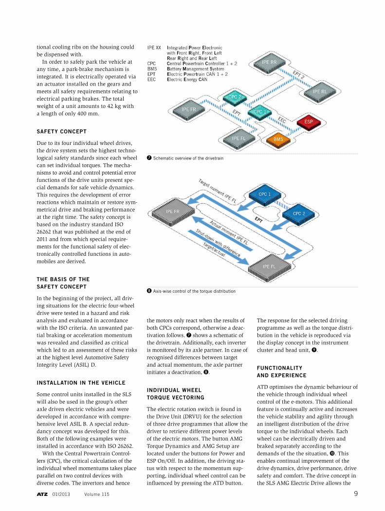
tional cooling ribs on the housing could be dispensed with.
In order to safely park the vehicle at any time, a park-brake mechanism is integrated. It is electrically operated via an actuator installed on the gears and meets all safety requirements relating to electrical parking brakes. The total weight of a unit amounts to 42 kg with a length of only 400 mm.
SAFETY CONCEPT
Due to its four individual wheel drives, the drive system sets the highest techno-logical safety standards since each wheel can set individual torques. The mecha-nisms to avoid and control potential error functions of the drive units present spe-cial demands for safe vehicle dynamics. This requires the development of error reactions which maintain or restore sym-metrical drive and braking performance at the right time. The safety concept is based on the industry standard ISO 26262 that was published at the end of 2011 and from which special require-ments for the functional safety of elec-tronically controlled functions in auto-mobiles are derived.
THE BASIS OF THE SAFETY CONCEPT
In the beginning of the project, all driv-ing situations for the electric four-wheel drive were tested in a hazard and risk analysis and evaluated in accordance with the ISO criteria. An unwanted par-tial braking or acceleration momentum was revealed and classified as critical which led to an assessment of these risks at the highest level Automotive Safety Integrity Level (ASIL) D.
INSTALLATION IN THE VEHICLE
Some control units installed in the SLS will also be used in the group’s other axle driven electric vehicles and were developed in accordance with compre-hensive level ASIL B. A special redun-dancy concept was developed for this. Both of the following examples were installed in accordance with ISO 26262.
With the Central Powertrain Control-lers (CPC), the critical calculation of the individual wheel momentums takes place parallel on two control devices with diverse codes. The invertors and hence
the motors only react when the results of both CPCs correspond, otherwise a deac-tivation follows. ❼ shows a schematic of the drivetrain. Additionally, each inverter is monitored by its axle partner. In case of recognised differences between target and actual momentum, the axle partner initiates a deactivation, ❽.
INDIVIDUAL WHEEL TORQUE VECTORING
The electric rotation switch is found in the Drive Unit (DRVU) for the selection of three drive programmes that allow the driver to retrieve different power levels of the electric motors. The button AMG Torque Dynamics and AMG Setup are located under the buttons for Power and ESP On/Off. In addition, the driving sta-tus with respect to the momentum sup-porting, individual wheel control can be influenced by pressing the ATD button.
The response for the selected driving programme as well as the torque distri-bution in the vehicle is reproduced via the display concept in the instrument cluster and head unit, ❾.
FUNCTIONALITY AND EXPERIENCE
ATD optimises the dynamic behaviour of the vehicle through individual wheel control of the e-motors. This additional feature is continually active and increases the vehicle stability and agility through an intelligent distribution of the drive torque to the individual wheels. Each wheel can be electrically driven and braked separately according to the demands of the the situation, ❿. This enables continual improvement of the drive dynamics, drive performance, drive safety and comfort. The drive concept in the SLS AMG Electric Drive allows the
❼ Schematic overview of the drivetrain
❽ Axis-wise control of the torque distribution
01i2013 Volume 115 9

maximum possible level of freedom via four individual wheel e-motors and thereby sets new standards in driving dynamics.
The gradation of ATD is experienced in three driving programmes: : Programme level C (Controlled Effi-
ciency): The vehicle is easily con-trolled and understeered. With over-steering a safe drive and stable driving state is reached with the help of the torque vectoring functionality for ESP control.
: Programme level S (Sport): The vehicle is balanced in the sport mode and exhibits almost neutral drive perfor-
mance. Drive dynamic manoeuvres with fast drive through are more of an experience due to yaw momentum support when steering.
: Programme level S+ (Sport plus): The vehicle is easily controlled in sport mode plus through which the potential of the wheel selective momentum con-trol mostly takes effect. The interac-tion of ESP and ATD control systems supports drive states in the limit area.
DYNAMIC POTENTIALS
The potentials when using ATD can be summarised as follows:
: increase of yaw reduction : reduction of the steering effort and
steering angle requirement : increased traction : minimisation of the ESP control
inputs.The driving situation is aligned with ATD from wheel to wheel through shift-ing of the drive and braking torque which improves the responding quali-ties when steering and reduces the over- and understeering tendency. The torque vectoring functionality reaches an opti-mum usage of the traction potential between the tyres and road in each driving state.
THANKS
The authors thank Frank Walter, Michael Klum-
bach, René-Christopher Wollmann, Dominik
Lange, Matthias Hey, Michael Himbert and
Rüdiger Kurz for their support.
❿ Functionality of the torque vectoring
❾ Elements of operation and display
COVER STORY ELEcTroMoBiLiTy
10