Embed Size (px)
Citation preview
The Effect of Cutting Parameters on Tool VibrationDuring Magnetorheological Fluid ControlledTurning BarP. Sam PaulDepartment of Mechanical Engineering, Karunya University, Coimbatore, 641114, Tamilnadu, India
Kolhar Sudeep SunilMarini India-Fayat Group, Gujarat 382110, India
A. S. VaradarajanNehru College of Engineering and Research Centre, Sampaul Thrissur, 678506, Kerala, India
(Received 27 August 2014; accepted 6 October 2014)
Tool vibration is a dynamic instability of the cutting process, which is a result of the interaction between the metalcutting process and the dynamics of a machine tool. The presence of such tool vibration leads to a poor surfacefinish, which results in cutting tool damage and the production of irritating and unacceptable noise. In orderto reduce tool vibration, a magnetorheological fluid damper was developed that will respond to an applied fieldwith a dramatic change in their rheological behaviour. The essential characteristic of these fluids is their abilityto reversibly change from a free-flowing, linear, viscous liquid to a semi-solid with a controllable yield strengthwithin milliseconds when exposed to a magnetic field. The present investigation aims to analyse the behaviourof a tool holder when attached with a magnetorheological damper during the turning operation using analyticaland experimental methods. A Mathematical model was developed and the amplitudes of the tool vibration andchip thickness were calculated. Cutting experiments were conducted to study the effect of the magnetorheologicaldamper on tool vibration, chip thickness etc. and to validate the results of the proposed mathematical model. Fromthe results, it was observed that the use of the magnetorheological damper reduces tool vibration effectively andits results matches the results obtained from the numerical method.
NOMENCLATUREm1 equivalent mass of tool holderm2 equivalent mass of damperC1 Damping constant of tool holderC2 Damping constant of damperk1 stiffness of tool holderx1(t) chip thicknessK2 stiffness of dampery2(t) amplitude of tool vibrationFt Forces acting in tool holderFd Forces acting due to damperMR Magnetorheological
1. INTRODUCTION
Tool vibration is a frequent problem in the manufacturingindustry, where metal cutting operations take place. Excessivetool vibrations during machining will increase the tool wearand cause poor surface finish.1 In metal cutting, tool vibra-tion is the most influential factor affecting the surface qual-ity of the machined surface.2 In order to reduce these vibra-tions and to obtain a better result in terms of surface finish,tool life, and other such factors, a magnetorheological damper
was developed. Spencer et al3 were the first among researcherswho tested MR Fluid techniques to isolate vibration and it wasfound that the rheological damper was more effective than theconventional viscous damper.4 Wang and Fei5 tried to suppresschatter in a boring bar by using electrorheological fluid. As aresult, they developed an on-line chatter detection and controlsystem. Genc and Phule6 observed that by varying the param-eters associated with MR fluids, such as volume, particle size,fraction of solids etc., the properties of the MR fluids can bevaried. It was also found that chatter could be suppressed moreeffectively by adjusting the damping and natural frequency ofthe system in a boring bar by using MR Fluid Dampers.7 Sathi-anarayanan et al.8 investigated method to improve dampingcapability by suppressing chatter in boring tools using an MRdamper. From the results they concluded that the MR damperreduces the possibility of chatter and improves the stability ofthe boring operation.
Bajkowski et al.9 described, analysed, and numerically sim-ulated a lumped mass model for a damper filled with a mag-netorheological fluid and established a solution for the quasistatic problem. Chen and Tsao10 proposed a new approach toanalyze the stability of cutting processes by considering the
International Journal of Acoustics and Vibration, Vol. 22, No. 1, 2017 (pp. 27–33) https://doi.org/10.20855/ijav.2017.22.1447 27
P. S. Paul, et al.: THE EFFECT OF CUTTING PARAMETERS ON TOOL VIBRATION DURING MAGNETORHEOLOGICAL FLUID CONTROLLED. . .
deformation of the work piece. They used partial differentialequations to describe the cutting in the turning process and aset of dynamic equations was considered based on the interac-tion between the tool and the workpiece. From the numericalresults, it was found that the critical chip width of the deformedcase was always larger than the rigid body case. Cesmeci etal.11 conducted an experimental and theoretical analysis tomodel the dynamic behavior of an MR damper on a conven-tional shock machine. A flow analysis of an MR damper wasdone based on the Bingham plastic constitutive model and theprediction results were compared against the test data. Thecomparisons showed that there was a very good agreementbetween the flow model and test results. Choi12 presenteda hysteresis model for the field-dependent damping force ofthe MR damper. The measured damping force was comparedwith the predicted ones from the Bingham model, Bouc-Wenmodel, and the proposed polynomial model. Furthermore, itwas demonstrated that the proposed polynomial model pre-dicted the non-linear hysteresis behavior of the MR damper atvarious operating conditions fairly well. Chooi and Olutunde13
presented a method for obtaining the exact solution represent-ing the flow of MR fluid through an annular gap.
Kwok et al.14 presented a new model for a magnetorheo-logical damper to represent the hysteretic relationship betweenthe damping force and the velocity. By using this new model,complexities arising from a larger number of model parameterswhen using the Bouc-Wen model were removed and the resultsobtained by this model matched well the experimental data.Liao and Hand15 studied the application of an MR fluid damperfor the vibration control of a Single-degree-of-freedom system.The characteristics of the MR damper were investigated usinganalytical and experimental methods and compared with thoseof the system with a conventional viscous damper. From theresults, it was observed that the MR damper provided effectivedamping for vibration isolation or suppression. Piotrowska etal.16 developed a novel two-degree-of-freedom model for themicro turning processes to show the effect of process kinemat-ics and tool edge serration in simulating the tool-work piecesystem behaviour. Sam Paul et al.17, 18 used a magnetorhe-ological damper to reduce tool vibration during hard turningwith minimal fluid application. For designing magnetorheo-logical damper, they considered parameters like the shape ofthe plunger, the viscosity of the oil, the size of the particle, andthe type of current. They also observed that the magnetorhe-ological damper had a considerable influence on tool wear.19
From the results, they observed that using Magneto rheolog-ical fluid damper, tool vibration can be reduced and cuttingperformance can be improved effectively. Sekar et al.20 pre-sented stability analysis in turning process with a coupled dy-namic model of cutting tool and tailstock supported workpiece.The effect of the cutting position, workpiece dimensions, cut-ter flexibility, and cutter damping on the dynamic stability waspresented with the dynamic model and they observed that theexperimental chatter establishes the stable states accurately inrough turning operations for the proposed model.
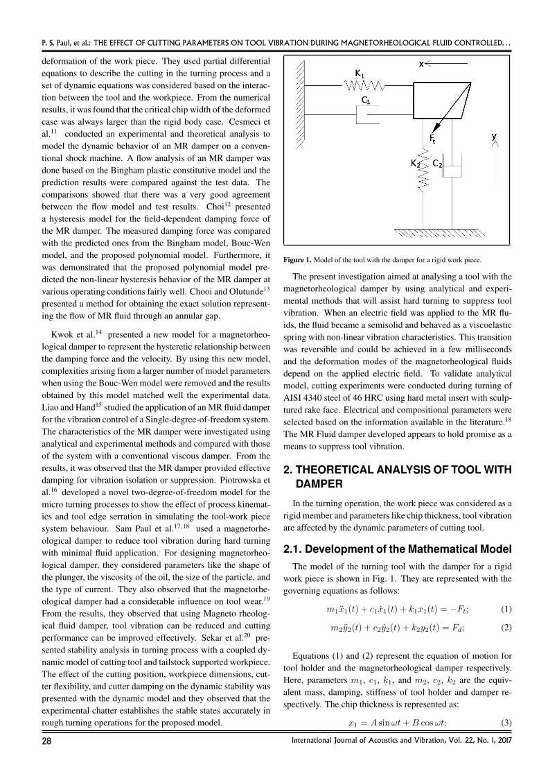
Figure 1. Model of the tool with the damper for a rigid work piece.
The present investigation aimed at analysing a tool with themagnetorheological damper by using analytical and experi-mental methods that will assist hard turning to suppress toolvibration. When an electric field was applied to the MR flu-ids, the fluid became a semisolid and behaved as a viscoelasticspring with non-linear vibration characteristics. This transitionwas reversible and could be achieved in a few millisecondsand the deformation modes of the magnetorheological fluidsdepend on the applied electric field. To validate analyticalmodel, cutting experiments were conducted during turning ofAISI 4340 steel of 46 HRC using hard metal insert with sculp-tured rake face. Electrical and compositional parameters wereselected based on the information available in the literature.18
The MR Fluid damper developed appears to hold promise as ameans to suppress tool vibration.
2. THEORETICAL ANALYSIS OF TOOL WITHDAMPER
In the turning operation, the work piece was considered as arigid member and parameters like chip thickness, tool vibrationare affected by the dynamic parameters of cutting tool.
2.1. Development of the Mathematical ModelThe model of the turning tool with the damper for a rigid
work piece is shown in Fig. 1. They are represented with thegoverning equations as follows:
m1x1(t) + c1x1(t) + k1x1(t) = −Ft; (1)
m2y2(t) + c2y2(t) + k2y2(t) = Fd; (2)
Equations (1) and (2) represent the equation of motion fortool holder and the magnetorheological damper respectively.Here, parameters m1, c1, k1, and m2, c2, k2 are the equiv-alent mass, damping, stiffness of tool holder and damper re-spectively. The chip thickness is represented as:
x1 = A sinωt+B cosωt; (3)
28 International Journal of Acoustics and Vibration, Vol. 22, No. 1, 2017
P. S. Paul, et al.: THE EFFECT OF CUTTING PARAMETERS ON TOOL VIBRATION DURING MAGNETORHEOLOGICAL FLUID CONTROLLED. . .
Table 1. Displacement, velocity, and acceleration values.
t = 0 t = π2ω
x1 = B x1 = A
y2 = D y2 = E
x1 = ωA x1 = −ωBy2 = ωE y2 = −ωD
x1 = −ω2B x1 = −ω2A
y2 = −ω2D y2 = −ω2E
The amplitude of the tool vibration was represented as;
y2 = E sinωt+D cosωt; (4)
Sekar et al.10 derived the equation for cutting force, which wasgiven as:
Ft = Cb {h0 − (x1(t)− x2(t))−− (x1(t− τ)− x2(t− τ))} cos θ. (5)
Spencer et al.11 derived the equation of damping force, whichwas given as:
Fd = Cbh0 {c0v − k0(y − y0) + yz} sin θ. (6)
In this investigation, two time spans, which represented theinitial time (t = 0) and the final time (t = π/2ω), were con-sidered in order to study the machining time. The values ofdisplacement, velocity, and acceleration at two time spans pre-sented in Table 1 are substituted in Eqs.(3) and (4) to calculateconstants A and B.
Substituting the necessary values of Table 1 in the Eq. (3)and further simplifying the equations resulted in the followingsolution:
B =−Ft[
−m1ω2 + ωc1(k1−m1ω2+ωc1)(k1−m1ω2−ωc1) + k1
] ; (7)
A =
[(k1 −m1ω
2 + ωc1)
(k1 −m1ω2 − ωc1)
] −Ft−m1ω2 + ωc1
(k1−m1ω2+ωc1)(k1−m1ω2−ωc1) + k1
. (8)
Similarly following results were obtained after simplifyingEq. (4).
D =Fd[
−m2ω2 + ωc2(k2−m2ω2+ωc2)(k2−m2ω2−ωc2) + k2
] ; (9)
E =
[(k2 −m2ω
2 + ωc2)
(k2 −m2ω2 − ωc2)
] Fd
−m2ω2 + ωc2(k2−m2ω2+ωc2)(k2−m2ω2−ωc2) + k2
. (10)
Ft= 527 N, m1 = 0.8 Kg, ω = 2+π+50060 = 52.3 Hz,
k1 = 20000 N/mm, ωn = 5200 Hz, C = 0.01 Ns/m. FromEqs. (3), (4), and (8) to (10), the chip thickness and amplitudeof tool vibration for the tool holder with the magnetorheolog-ical damper were calculated. On substituting the constant val-ues and by applying boundary conditions, it was found that theamplitude of tool vibration (y2) was found to be 0.029 mm andthe chip thickness (X1) was observed to be 1.25 mm.
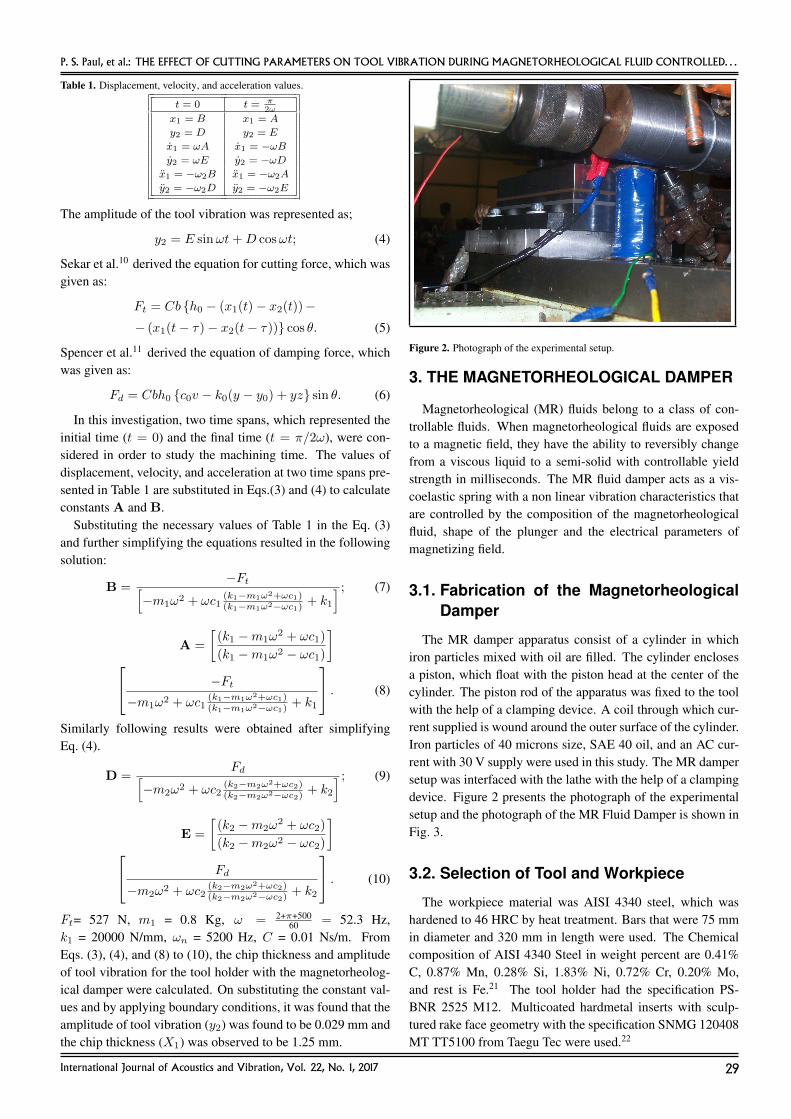
Figure 2. Photograph of the experimental setup.
3. THE MAGNETORHEOLOGICAL DAMPER
Magnetorheological (MR) fluids belong to a class of con-trollable fluids. When magnetorheological fluids are exposedto a magnetic field, they have the ability to reversibly changefrom a viscous liquid to a semi-solid with controllable yieldstrength in milliseconds. The MR fluid damper acts as a vis-coelastic spring with a non linear vibration characteristics thatare controlled by the composition of the magnetorheologicalfluid, shape of the plunger and the electrical parameters ofmagnetizing field.
3.1. Fabrication of the MagnetorheologicalDamper
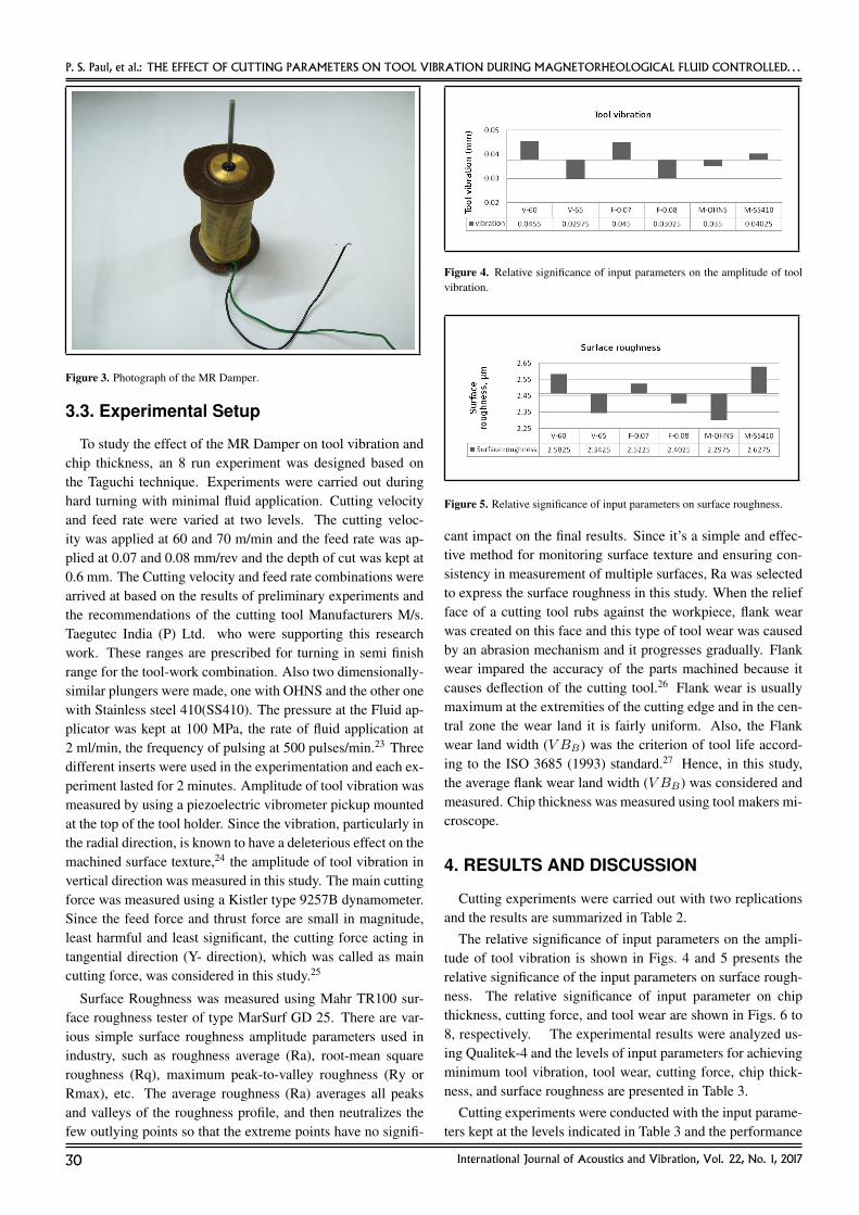
The MR damper apparatus consist of a cylinder in whichiron particles mixed with oil are filled. The cylinder enclosesa piston, which float with the piston head at the center of thecylinder. The piston rod of the apparatus was fixed to the toolwith the help of a clamping device. A coil through which cur-rent supplied is wound around the outer surface of the cylinder.Iron particles of 40 microns size, SAE 40 oil, and an AC cur-rent with 30 V supply were used in this study. The MR dampersetup was interfaced with the lathe with the help of a clampingdevice. Figure 2 presents the photograph of the experimentalsetup and the photograph of the MR Fluid Damper is shown inFig. 3.
3.2. Selection of Tool and Workpiece
The workpiece material was AISI 4340 steel, which washardened to 46 HRC by heat treatment. Bars that were 75 mmin diameter and 320 mm in length were used. The Chemicalcomposition of AISI 4340 Steel in weight percent are 0.41%C, 0.87% Mn, 0.28% Si, 1.83% Ni, 0.72% Cr, 0.20% Mo,and rest is Fe.21 The tool holder had the specification PS-BNR 2525 M12. Multicoated hardmetal inserts with sculp-tured rake face geometry with the specification SNMG 120408MT TT5100 from Taegu Tec were used.22
International Journal of Acoustics and Vibration, Vol. 22, No. 1, 2017 29
P. S. Paul, et al.: THE EFFECT OF CUTTING PARAMETERS ON TOOL VIBRATION DURING MAGNETORHEOLOGICAL FLUID CONTROLLED. . .
Figure 3. Photograph of the MR Damper.
3.3. Experimental Setup
To study the effect of the MR Damper on tool vibration andchip thickness, an 8 run experiment was designed based onthe Taguchi technique. Experiments were carried out duringhard turning with minimal fluid application. Cutting velocityand feed rate were varied at two levels. The cutting veloc-ity was applied at 60 and 70 m/min and the feed rate was ap-plied at 0.07 and 0.08 mm/rev and the depth of cut was kept at0.6 mm. The Cutting velocity and feed rate combinations werearrived at based on the results of preliminary experiments andthe recommendations of the cutting tool Manufacturers M/s.Taegutec India (P) Ltd. who were supporting this researchwork. These ranges are prescribed for turning in semi finishrange for the tool-work combination. Also two dimensionally-similar plungers were made, one with OHNS and the other onewith Stainless steel 410(SS410). The pressure at the Fluid ap-plicator was kept at 100 MPa, the rate of fluid application at2 ml/min, the frequency of pulsing at 500 pulses/min.23 Threedifferent inserts were used in the experimentation and each ex-periment lasted for 2 minutes. Amplitude of tool vibration wasmeasured by using a piezoelectric vibrometer pickup mountedat the top of the tool holder. Since the vibration, particularly inthe radial direction, is known to have a deleterious effect on themachined surface texture,24 the amplitude of tool vibration invertical direction was measured in this study. The main cuttingforce was measured using a Kistler type 9257B dynamometer.Since the feed force and thrust force are small in magnitude,least harmful and least significant, the cutting force acting intangential direction (Y- direction), which was called as maincutting force, was considered in this study.25
Surface Roughness was measured using Mahr TR100 sur-face roughness tester of type MarSurf GD 25. There are var-ious simple surface roughness amplitude parameters used inindustry, such as roughness average (Ra), root-mean squareroughness (Rq), maximum peak-to-valley roughness (Ry orRmax), etc. The average roughness (Ra) averages all peaksand valleys of the roughness profile, and then neutralizes thefew outlying points so that the extreme points have no signifi-
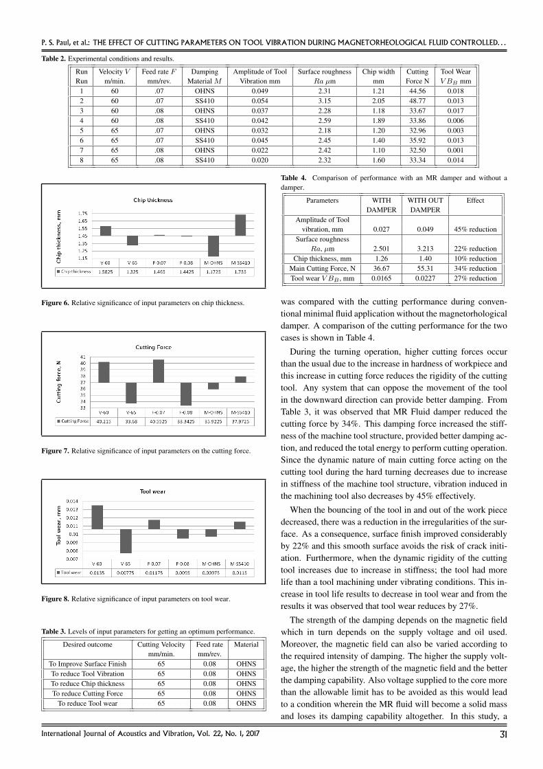
Figure 4. Relative significance of input parameters on the amplitude of toolvibration.
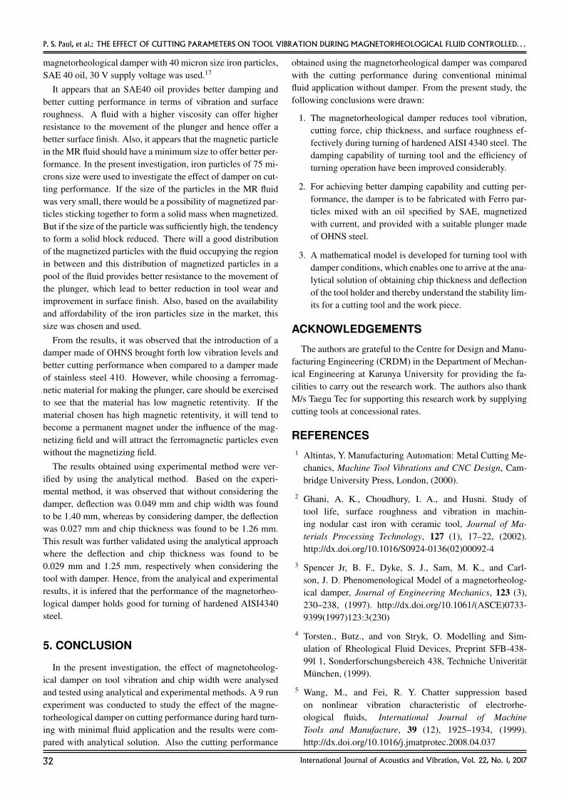
Figure 5. Relative significance of input parameters on surface roughness.
cant impact on the final results. Since it’s a simple and effec-tive method for monitoring surface texture and ensuring con-sistency in measurement of multiple surfaces, Ra was selectedto express the surface roughness in this study. When the reliefface of a cutting tool rubs against the workpiece, flank wearwas created on this face and this type of tool wear was causedby an abrasion mechanism and it progresses gradually. Flankwear impared the accuracy of the parts machined because itcauses deflection of the cutting tool.26 Flank wear is usuallymaximum at the extremities of the cutting edge and in the cen-tral zone the wear land it is fairly uniform. Also, the Flankwear land width (V BB) was the criterion of tool life accord-ing to the ISO 3685 (1993) standard.27 Hence, in this study,the average flank wear land width (V BB) was considered andmeasured. Chip thickness was measured using tool makers mi-croscope.
4. RESULTS AND DISCUSSION
Cutting experiments were carried out with two replicationsand the results are summarized in Table 2.
The relative significance of input parameters on the ampli-tude of tool vibration is shown in Figs. 4 and 5 presents therelative significance of the input parameters on surface rough-ness. The relative significance of input parameter on chipthickness, cutting force, and tool wear are shown in Figs. 6 to8, respectively. The experimental results were analyzed us-ing Qualitek-4 and the levels of input parameters for achievingminimum tool vibration, tool wear, cutting force, chip thick-ness, and surface roughness are presented in Table 3.
Cutting experiments were conducted with the input parame-ters kept at the levels indicated in Table 3 and the performance
30 International Journal of Acoustics and Vibration, Vol. 22, No. 1, 2017
P. S. Paul, et al.: THE EFFECT OF CUTTING PARAMETERS ON TOOL VIBRATION DURING MAGNETORHEOLOGICAL FLUID CONTROLLED. . .
Table 2. Experimental conditions and results.
Run Velocity V Feed rate F Damping Amplitude of Tool Surface roughness Chip width Cutting Tool WearRun m/min. mm/rev. Material M Vibration mm Ra µm mm Force N V BB mm
1 60 .07 OHNS 0.049 2.31 1.21 44.56 0.0182 60 .07 SS410 0.054 3.15 2.05 48.77 0.0133 60 .08 OHNS 0.037 2.28 1.18 33.67 0.0174 60 .08 SS410 0.042 2.59 1.89 33.86 0.0065 65 .07 OHNS 0.032 2.18 1.20 32.96 0.0036 65 .07 SS410 0.045 2.45 1.40 35.92 0.0137 65 .08 OHNS 0.022 2.42 1.10 32.50 0.0018 65 .08 SS410 0.020 2.32 1.60 33.34 0.014
Figure 6. Relative significance of input parameters on chip thickness.
Figure 7. Relative significance of input parameters on the cutting force.
Figure 8. Relative significance of input parameters on tool wear.
Table 3. Levels of input parameters for getting an optimum performance.
Desired outcome Cutting Velocity Feed rate Materialmm/min. mm/rev.
To Improve Surface Finish 65 0.08 OHNSTo reduce Tool Vibration 65 0.08 OHNSTo reduce Chip thickness 65 0.08 OHNSTo reduce Cutting Force 65 0.08 OHNS
To reduce Tool wear 65 0.08 OHNS
Table 4. Comparison of performance with an MR damper and without adamper.
Parameters WITH WITH OUT EffectDAMPER DAMPER
Amplitude of Toolvibration, mm 0.027 0.049 45% reduction
Surface roughnessRa, µm 2.501 3.213 22% reduction
Chip thickness, mm 1.26 1.40 10% reductionMain Cutting Force, N 36.67 55.31 34% reductionTool wear V BB , mm 0.0165 0.0227 27% reduction
was compared with the cutting performance during conven-tional minimal fluid application without the magnetorhologicaldamper. A comparison of the cutting performance for the twocases is shown in Table 4.
During the turning operation, higher cutting forces occurthan the usual due to the increase in hardness of workpiece andthis increase in cutting force reduces the rigidity of the cuttingtool. Any system that can oppose the movement of the toolin the downward direction can provide better damping. FromTable 3, it was observed that MR Fluid damper reduced thecutting force by 34%. This damping force increased the stiff-ness of the machine tool structure, provided better damping ac-tion, and reduced the total energy to perform cutting operation.Since the dynamic nature of main cutting force acting on thecutting tool during the hard turning decreases due to increasein stiffness of the machine tool structure, vibration induced inthe machining tool also decreases by 45% effectively.
When the bouncing of the tool in and out of the work piecedecreased, there was a reduction in the irregularities of the sur-face. As a consequence, surface finish improved considerablyby 22% and this smooth surface avoids the risk of crack initi-ation. Furthermore, when the dynamic rigidity of the cuttingtool increases due to increase in stiffness; the tool had morelife than a tool machining under vibrating conditions. This in-crease in tool life results to decrease in tool wear and from theresults it was observed that tool wear reduces by 27%.
The strength of the damping depends on the magnetic fieldwhich in turn depends on the supply voltage and oil used.Moreover, the magnetic field can also be varied according tothe required intensity of damping. The higher the supply volt-age, the higher the strength of the magnetic field and the betterthe damping capability. Also voltage supplied to the core morethan the allowable limit has to be avoided as this would leadto a condition wherein the MR fluid will become a solid massand loses its damping capability altogether. In this study, a
International Journal of Acoustics and Vibration, Vol. 22, No. 1, 2017 31
P. S. Paul, et al.: THE EFFECT OF CUTTING PARAMETERS ON TOOL VIBRATION DURING MAGNETORHEOLOGICAL FLUID CONTROLLED. . .
magnetorheological damper with 40 micron size iron particles,SAE 40 oil, 30 V supply voltage was used.17
It appears that an SAE40 oil provides better damping andbetter cutting performance in terms of vibration and surfaceroughness. A fluid with a higher viscosity can offer higherresistance to the movement of the plunger and hence offer abetter surface finish. Also, it appears that the magnetic particlein the MR fluid should have a minimum size to offer better per-formance. In the present investigation, iron particles of 75 mi-crons size were used to investigate the effect of damper on cut-ting performance. If the size of the particles in the MR fluidwas very small, there would be a possibility of magnetized par-ticles sticking together to form a solid mass when magnetized.But if the size of the particle was sufficiently high, the tendencyto form a solid block reduced. There will a good distributionof the magnetized particles with the fluid occupying the regionin between and this distribution of magnetized particles in apool of the fluid provides better resistance to the movement ofthe plunger, which lead to better reduction in tool wear andimprovement in surface finish. Also, based on the availabilityand affordability of the iron particles size in the market, thissize was chosen and used.
From the results, it was observed that the introduction of adamper made of OHNS brought forth low vibration levels andbetter cutting performance when compared to a damper madeof stainless steel 410. However, while choosing a ferromag-netic material for making the plunger, care should be exercisedto see that the material has low magnetic retentivity. If thematerial chosen has high magnetic retentivity, it will tend tobecome a permanent magnet under the influence of the mag-netizing field and will attract the ferromagnetic particles evenwithout the magnetizing field.
The results obtained using experimental method were ver-ified by using the analytical method. Based on the experi-mental method, it was observed that without considering thedamper, deflection was 0.049 mm and chip width was foundto be 1.40 mm, whereas by considering damper, the deflectionwas 0.027 mm and chip thickness was found to be 1.26 mm.This result was further validated using the analytical approachwhere the deflection and chip thickness was found to be0.029 mm and 1.25 mm, respectively when considering thetool with damper. Hence, from the analyical and experimentalresults, it is infered that the performance of the magnetorheo-logical damper holds good for turning of hardened AISI4340steel.
5. CONCLUSION
In the present investigation, the effect of magnetoheolog-ical damper on tool vibration and chip width were analysedand tested using analytical and experimental methods. A 9 runexperiment was conducted to study the effect of the magne-torheological damper on cutting performance during hard turn-ing with minimal fluid application and the results were com-pared with analytical solution. Also the cutting performance
obtained using the magnetorheological damper was comparedwith the cutting performance during conventional minimalfluid application without damper. From the present study, thefollowing conclusions were drawn:
1. The magnetorheological damper reduces tool vibration,cutting force, chip thickness, and surface roughness ef-fectively during turning of hardened AISI 4340 steel. Thedamping capability of turning tool and the efficiency ofturning operation have been improved considerably.
2. For achieving better damping capability and cutting per-formance, the damper is to be fabricated with Ferro par-ticles mixed with an oil specified by SAE, magnetizedwith current, and provided with a suitable plunger madeof OHNS steel.
3. A mathematical model is developed for turning tool withdamper conditions, which enables one to arrive at the ana-lytical solution of obtaining chip thickness and deflectionof the tool holder and thereby understand the stability lim-its for a cutting tool and the work piece.
ACKNOWLEDGEMENTS
The authors are grateful to the Centre for Design and Manu-facturing Engineering (CRDM) in the Department of Mechan-ical Engineering at Karunya University for providing the fa-cilities to carry out the research work. The authors also thankM/s Taegu Tec for supporting this research work by supplyingcutting tools at concessional rates.
REFERENCES1 Altintas, Y. Manufacturing Automation: Metal Cutting Me-
chanics, Machine Tool Vibrations and CNC Design, Cam-bridge University Press, London, (2000).
2 Ghani, A. K., Choudhury, I. A., and Husni. Study oftool life, surface roughness and vibration in machin-ing nodular cast iron with ceramic tool, Journal of Ma-terials Processing Technology, 127 (1), 17–22, (2002).http://dx.doi.org/10.1016/S0924-0136(02)00092-4
3 Spencer Jr, B. F., Dyke, S. J., Sam, M. K., and Carl-son, J. D. Phenomenological Model of a magnetorheolog-ical damper, Journal of Engineering Mechanics, 123 (3),230–238, (1997). http://dx.doi.org/10.1061/(ASCE)0733-9399(1997)123:3(230)
4 Torsten., Butz., and von Stryk, O. Modelling and Sim-ulation of Rheological Fluid Devices, Preprint SFB-438-99l 1, Sonderforschungsbereich 438, Techniche UniveritatMunchen, (1999).
5 Wang, M., and Fei, R. Y. Chatter suppression basedon nonlinear vibration characteristic of electrorhe-ological fluids, International Journal of MachineTools and Manufacture, 39 (12), 1925–1934, (1999).http://dx.doi.org/10.1016/j.jmatprotec.2008.04.037
32 International Journal of Acoustics and Vibration, Vol. 22, No. 1, 2017
P. S. Paul, et al.: THE EFFECT OF CUTTING PARAMETERS ON TOOL VIBRATION DURING MAGNETORHEOLOGICAL FLUID CONTROLLED. . .
6 Genc, S., and Phule, P. P. Rheological Properties of Mag-netorheological Fluids, Smart Materials and Structures,11 (1), 140–146, (2002). http://dx.doi.org/10.1088/0964-1726/11/1/316
7 Deqing Mei., Tianrong Kong., Albert, J., and ShihZichen Chen. Magnetorheological fluid-controlled bor-ing bar for chatter suppression, Journal of materi-als processing technology, 209 (4), 1861–1870, (2009).http://dx.doi.org/10.1016/j.jmatprotec.2008.04.037
8 Sathianarayanan, D., Karunamoorthy, L., Srini-vasan, J., Kandasami, G. S., and Palanikumar, K.Chatter Suppression in Boring Operation UsingMagnetorheological Fluid Damper, Materials andManufacturing processes, 23 (4), 29–335, (2008).http://dx.doi.org/10.1080/10426910701860897
9 Bajkowski, J., Nachman, J., Shillor, M., and Sofonea,M. A model for a magnetorheological damper, Mathemat-ical and Computer Modelling, 48 (12), 56–68, (2007).http://dx.doi.org/10.1016/j.mcm.2007.08.014
10 Chen, C. K., and Tsao, Y. M. A stability analysis of re-generative chatter in turning process without using tail-stock, Int J Adv Manuf Technol, 29 (7–8), 648–654, (2006).http://dx.doi.org/10.1007/s00170-005-2573-5
11 Cesmeci, S., and Engin, T. Modeling and testing of a field-controllable magnetorheological fluid damper, Interna-tional Journal of Mechanical Sciences, 52 (8), 1036–1046,(2010). http://dx.doi.org/10.1016/j.ijmecsci.2010.04.007
12 Choi, S. B., Lee, S. K., and Park, Y. P. A hysteresis modelfor the field-dependent damping force of a magnetorheo-logical damper, Journal of Sound and vibration, 245 (2),375–383, (2001). http://dx.doi.org/10.1006/jsvi.2000.3539
13 Chooi, W. W., and Olutunde, O. S. Mathematical Model-ing, Analysis, and Design of Magnetorheological Dampers,Journal of Vibration and Acoustics, 131 (6), 1–10, (2009).http://dx.doi.org/10.1115/1.3142884
14 Kwok, N. M., Ha, Q. P., Nguyen, T. H., Li, J.,and Samali, B. A novel hysteretic model for mag-netorheological fluid dampers and parameter identifica-tion using particle swarm optimization, Sensors andActuators A: Physical, 132 (2), 441–451, (2006).http://dx.doi.org/10.1016/j.sna.2006.03.015
15 Liao, W., and Hand Lai, C. Y. Harmonic analysisof a magnetorheological damper for vibration control,Smart Materials and Structures, 11, 288–296, (2002).http://dx.doi.org/10.1088/0964-1726/11/2/312
16 Piotrowska, I., Brandt, C., Karimi, H., and Maass.P. Mathematical model of micro turning process,Int J Adv Manuf. Technol, 45 (1), 33–40, (2009).http://dx.doi.org/10.1007/s00170-009-1932-z
17 Sam Paul, P., and Varadarajan,. A. S. Effect of magnetorheological damper on tool vibration during hard turn-ing., Frontiers in Mechanical Engineering, 7 (4), 410–416,(2012). http://dx.doi.org/10.1007/s11465-012-0341-4
18 Sam Paul, P., Varadarajan,. A. S., Ajay vasanth, X., andLawrance G. Effect of magnetic field on damping ability ofmagnetorheological damper during hard turning, Archivesof civil and mechanical Engineering, 14 (3), 433–444,(2014). http://dx.doi.org/10.1016/j.acme.2013.11.001
19 Sam Paul, P., Varadarajan, A. S., and Mohanasun-daram, S. Effect of magnetorheological fluid on toolwear during hard turning with minimal fluid application,Archives of civil and mechanical Engineering, 15(1), 124–132, (2015). http://dx.doi.org/10.1016/j.acme.2014.03.007http://dx.doi.org/10.1016/j.acme.2014.03.007
20 Sekar, M., Srinivas, J., Kotaiah, KR., and Yang, S. H. Sta-bility analysis of turning process with tailstock-supportedworkpiece, Int J Adv Manuf Technol, 43, 862–871, (2009).http://dx.doi.org/10.1007/s00170-008-1764-2
21 Sam Paul, P., and Varadarajan, A. S. A multi-sensorfusion model based on an artificial neural networkto predict tool wear during hard turning, Journal ofEngineering Manufacture, 226 (5), 853–860, (2012).http://dx.doi.org/10.1177/0954405411432381
22 Sam Paul, P., and Varadarajan, A. S. Performance evalua-tion of hard turning of AISI 4340 steel with minimal fluidapplication in the presence of semi-solid lubricants, Jour-nal of Engineering Tribology, 227 (7), 739–748, (2013).http://dx.doi.org/10.1177/1350650112468376
23 Varadarajan, A. S., Philip, P. K., and Ramamoorthy,B. Investigations on hard turning with minimal cut-ting fluid application (HTMF) and its comparison withdry and wet turning, International Journal of Ma-chine Tools and Manufacture, 42 (2), 193–200, (2002).http://dx.doi.org/10.1016/S0890-6955(01)00119-5
24 Moon, K. S., and Sutherland, J. W. The Origin and Inter-pretation of Spatial Frequencies in a Turned Surface Profile,Journal of Engineering for Industry, Trans. ASME, 116 (3),340-347, (1994). http://dx.doi.org/10.1115/1.2901950
25 Kistler. Guide to the measurement of force, The institute ofMeasurement and Control ISBN 0 904457 28 1, London,(1998).
26 Stephenson, D. A., and Agapiou, J. S. Metal Cutting Theoryand Practice, Marcel Dekker, New York, (1997).
27 International Organization for Standardization, Tool-lifetesting with single point turning tools, ISO 3685-1993(E), 2nd Edition, Case Postale 56, CH-1211 Geneva 20,Switzerland,(1993). URL https://www.evs.ee/preview/iso-3685-1993-en.pdf
International Journal of Acoustics and Vibration, Vol. 22, No. 1, 2017 33