Embed Size (px)
Citation preview

THE DEVELOPMENT OF THE LOCOMOTION PERFORMANCE MODEL (LPM) FOR THE EXOMARS ROVER VEHICLE
Paul Meacham (1), Nuno Silva (1), Richard Lancaster (1)
(1) Astrium Ltd., Gunnels Wood Road, Stevenage, SG1 2AS, UK, Email: [email protected]
ABSTRACT
ExoMars is a European Space Agency mission to send an Orbiter and an Entry, Descent & Landing demonstrator to Mars in 2016, followed by a Rover in 2018. The mission goal is to establish if life has ever existed on the surface of Mars. Astrium Ltd are responsible for the Rover Vehicle, the elements of the Rover excluding payload. The development of the ExoMars Rover Vehicle requires a unique model philosophy to develop and qualify the mission requirements, which differs considerably from a ‘standard’ spacecraft. One of the key models in the development of the required autonomous driving capability is the Locomotion Performance Model (LPM). The LPM is a breadboard of Mars-representative weight that incorporates a suite of COTS sensors and actuators that are functionally equivalent to the sensors/actuators used on the flight Rover Vehicle for autonomous driving. This paper describes the role of the LPM in the context of the Rover Vehicle, its initial configuration and the subsequent modifications made to it, in order to meet the needs of the Mobility system. The sensor/actuator suite on the LPM and its relationship to the flight equivalent is explored. The LPM GNC Algorithms Cradle, a piece of software which allows proto-flight GNC algorithms to run on the LPM, is described in detail, including how it replicates the flight processing environment. 1. OVERVIEW OF THE EXOMARS MISSION
ExoMars (Exobiology on Mars) is a planned European Space Agency mission to Mars to search for possible biosignatures of Martian life, past or present. The mission is divided into two parts, both in collaboration with the Russian Space Agency, Roscosmos. The first part consists of a Trace Gas Orbiter (TGO) and an Entry, Descent and Landing Demonstrator Module (EDM), to be launched in 2016. The second part features a 300kg, six-wheeled Rover along with a supporting carrier module and EDM. The Rover Module (shown in Fig. 1) is used to meet the ExoMars science objectives of surface mobility, access to the subsurface to acquire samples and sample
acquisition, preparation, distribution and analysis. The Rover Module is the responsibility of Thales Alenia Space (Italy). The Rover Vehicle, which is defined as the Rover Module less the scientific instruments and the drill, is the responsibility of Astrium Ltd.
Stereo Navigation CamerasScience Cameras
Sun Sensor
Rear Bogie
Left Front Bogie
WISDOM ground penetrating radar attached to rear of Rover
Pan Tilt Mechanism
Wheel
Steering Motor
Drive Motor
Subsurface Drill
Stereo Localisation Cameras
Solar Panels
Figure 1. ExoMars Rover
The Rover Vehicle is highly autonomous and is designed to allow an operator on Earth to designate target destinations for the Rover to travel to, but no further information on terrain or optimal paths. The Rover Vehicle is then able to perceive the terrain immediately surrounding it, analyse it and path a path through it, avoiding hazardous terrain features. The Rover Vehicle will drive the planned path, correcting for disturbances as it does so. This process will repeat until the specified target has been reached. 2. MODEL PHILOSOPHY
The overall development and verification of the Rover Vehicle is supported by adequate models at all levels and stages with the objectives of achieving, as necessary: The qualification of each equipment and subsystem,
as well as the qualification of the overall vehicle from the following points of view: Mechanical, Thermal, Electromagnetic, RF, Electrical, Functional and Performance.
The on-board software verification. The qualification of the RV operations. The full acceptance of each flight equipment, as
well as the acceptance of the overall vehicle Definition of realistic development sequence in
order to ensure the schedule, to secure the industrial

aspects and the production of the flight model Ensuring the design suitability and compliance to
the technical and industrial requirements by means of proper verification at different levels, performed throughout the development sequence
The summation of all the models required to meet these objectives forms the Rover Vehicle model philosophy. This philosophy is considerably different to other spacecraft and reflects both the different challenges of a Mars surface mission as well as the maturity of the technologies required by the Rover Vehicle. The models are as follows: Locomotion Performance Model (LPM) Mobility Development Model (MDM) Locomotion Verification Model (LVM) Functional Validation Bench (FVB) Hybrid Software Verification Facility (HSVF) Numerical Software Verification Facility (NSVF) Electrical Test Model (ETM) Structural Thermal Model (STM) Proto Flight Model (PFM) The subject of this paper, the Locomotion Performance Model, is one of the first models produced under the model philosophy and is described in more detail in the following section. 3. LOCOMOTION PERFORMANCE MODEL
3.1. Introduction
The Locomotion Performance Model (LPM), shown in Fig. 2, is used to develop the mobility functionality and performance of the Rover Vehicle. In particular, the LPM is essential in achieving the goal of TRL 6, defined as “system/subsystem model or prototype demonstration in a relevant environment (ground or space)” in [1], for the Guidance Navigation and Control (GNC) algorithms that provide the ability to autonomously traverse the Martian terrain, by the Rover Vehicle’s Delta Preliminary Design Review (PDR). The LPM is designed and managed to have a mass of ~38% of the flight model so that the loads on the locomotion system are representative of those seen on Mars (motor torque, wheel/soil interaction, etc) although the LPM is not specifically used for the verification of the locomotion system – this is the role of the Locomotion Verification Model (LVM). Instead, the Mars-representative weight allows the GNC algorithms to be tuned for the flight Rover’s responses when driving over the expected terrain. The LPM incorporates a suite of Commercial Off-The-Shelf (COTS) sensors and actuators that are designed to be functionally equivalent to the sensors/actuators used on the flight Rover Vehicle for autonomous traverses.
Figure 2, Locomotion Performance Model
The initial configuration of the LPM was the merged combination of breadboards and equipments procured during Phase B1 of the Rover Vehicle project. These subcontracts provided the chassis and locomotion system for the LPM, a vision system designed to be representative of the flight Navigation Cameras (NavCams) and some basic autonomous traverse algorithms. These algorithms have now been superseded by the GNC algorithms, and therefore will not be explored in this paper. The LPM has subsequently been modified and updated through Phases B2X and B2X2 to more closely reflect the functional capabilities of the flight Rover, as well as the addition of further sensors required by the GNC algorithms - specifically a vision system designed to be representative of the flight Localisation Cameras and an inertial reference system functionally similar to the flight Inertial Measurement Unit (IMU). In addition, a ground truth subsystem has been added to provide a mechanism for checking the estimated position and attitude of the LPM against the actual position and attitude. The current architecture of the LPM is shown in Fig. 3.

Figure 3. LPM System Architecture
The subsystems that comprise the LPM and their relation to the flight Rover Vehicle equivalent are explored in the following sections. 3.2. MDA Chassis & Locomotion Subsystem
The LPM’s Chassis & Locomotion Subsystem (CLS), shown in Fig. 4, consists of a Rover chassis and locomotion system with control software running on a LEON2 processor, provided as part of a Phase B1 breadboard subcontract with MDA Robotics of Canada.
Figure 4. MDA Chassis & Locomotion Subsystem
The MDA CLS is a six-wheeled vehicle supporting a main chassis. The wheels are configured as three pairs with each pair attached to a single bogie. Two bogies attach to the side of the main chassis and the third is attached to the rear of the chassis, perpendicular to the direction of movement. All bogies are free to rotate around the attachment. The MDA CLS is propelled by six electric drives located in the hubs of the wheels. Each wheel is connected to a leg which may be rotated with similar electric drives round the wheel axis so the MDA CLS may perform a variety of steering movements, including: Point Turn (Fig. 5)
- where the Rover spins on the spot Crab Motion (Fig. 6)
- where the Rover aligns all wheels to the same angle and moves along the vector described by that angle
Simple Ackermann (Fig. 7) - where the Rover follows a curve of constant
radius with its centre along the middle wheel axis
Generic Ackermann (Fig. 8) - where the Rover combines simple Ackermann
motion with crab motion
Figure 5. MDA CLS Point Turn
Figure 6. MDA CLS Crab Motion
Figure 7. MDA CLS Simple Ackermann
Figure 8. MDA CLS Generic Ackermann

These motion modes are equivalent to the flight motion modes, although Generic Point Turn (where the Rover can manipulate the location of the centre point of a point turn relative to the Rover body) is not present on the LPM due to the limitations of the steering range. The legs themselves may be rotated with electric drives round the interface with the bogie, so the CLS is able to wheel walk, i.e. the MDA CLS has six-wheel drive, steer and walk capability. Absolute and incremental encoders are used to measure the angular displacement of the three bogies and all motor positions and rates. 3.3. Magellium Vision Subsystem
The first of the LPM’s Vision Subsystems (VS) is designed to be functionally representative of the flight Rover’s Navigation Cameras (NavCams) and consists of a pair of stereoscopic cameras, a pan and tilt unit (PTU), carbon fibre mast and control software, provided as part of a Phase B1 breadboard subcontract with Magellium (France). It is shown in Fig. 9. The mast, PTU and cameras are positioned such that the centre of the camera’s field-of-view (FOV), when the cameras are pointing directly forward, is 2m above ground level, consistent with the flight equivalent.
Figure 9. Magellium Vision Subsystem
The camera sensor is a CMOS sensor which allows 1280x1024 monochromatic image acquisitions. The camera lens has a focal length of 4.8mm which when combined with the sensor gives a FOV of 69°. The stereo baseline of the cameras is 100mm which gives the ground field of view given in Table 1.
Table 1. Magellium VS Ground FOV
However, the FOV and stereo baseline are no longer representative of the flight NavCams, and the Magellium VS is intended to be replaced with breadboard NavCams from the flight NavCam supplier. The PTU allows the stereo bench to have a tilt range of ±90° and a pan range of ±175°. The tilt range is equivalent to the range of the flight equipment; the range of pan angles on the flight equipment is 10° wider at each end of the range. However, since the limits of the pan range are never used, this does not pose issues for the work done with the LPM. 3.4. Stemmer Vision Subsystem
The second of the LPM’s Vision Subsystems (VS) is designed to be functionally representative of the flight Rover’s Localisation Cameras (LocCams) and consists of a pair of stereoscopic cameras and control software, provided as part of a Phase B2X2 equipment procurement with Stemmer Imaging (UK) – see Fig. 10.
Figure 10. Stemmer Vision Subsystem
Each camera is a 1.4 megapixel CCD monochrome sensor combined with a lens of focal length 4.8mm. This gives a FOV of 69°. The stereo baseline between the two cameras is 100mm (as with the Magellium VS), and the centre of each camera FOV is positioned 0.9m above ground level, with a fixed pointing of 13° below the horizontal plane as shown in Figs. 11 and 12.
Figure 11. Stemmer VS Vertical Position

Figure 12. Stemmer VS Pointing
Like the Magellium equivalent, the FOV and stereo baseline are no longer representative of the flight LocCams and the Stemmer VS is intended to be replaced with the same breadboard NavCams from the flight NavCam supplier as the Magellium VS, but mounted in the LocCam position. Further, the pointing angle of the flight LocCams has increased to 18° below the horizontal plane. However, the mounting position of the Stemmer VS is designed to be equivalent with the flight LocCams so this element is representative. 3.5. Memsense Inertial Reference Subsystem
The LPM’s Inertial Reference Subsystem (IRS) consists of a MEMS Inertial Measurement Unit (IMU) and supporting software that was procured from Memsense (USA) in Phase B2X2. It is shown in Fig. 13
Figure 13. Memsense Inertial Reference Subsystem
The IMU is capable of measuring acceleration (through 3-axis accelerometers), angular rates (through 3-axis gyroscopes) and magnetic field strength (through 3-axis magnetometers), although only the first two of these are actively acquired by the LPM as the flight equivalent unit does not feature any magnetic field measurements.
The technology used in the flight IMU, which could be part-MEMS, has yet to be decided so it is not yet possible to compare the Memsense IRS with its flight equivalent in any further detail. However, the Memsense IRS was chosen to approximately match the specified performance of the flight IMU over the same operational range.
The Memsense IRS has dynamic range of 10g (acceleration) and 150°/s (angular rate), with a bandwidth of 50Hz. 3.6. Inition Ground Truth Subsystem
The LPM’s Ground Truth Subsystem (GTS) consists of a camera/IMU unit and supporting software which was part of a Phase B2X subcontract for the procurement and installation of a motion tracking system developed by Intersense (USA) and installed by Inition (UK).
Figure 14. Inition Ground Truth Subsystem
The Inition GTS is a 6 degree-of-freedom motion tracking system for determining the position and attitude of the LPM within the confines of the Astrium Ltd. Mars Yard. The main element of the GTS is the InertiaCam (shown in Fig. 14), a high resolution optical-inertial sensor which integrates 6 MEMS inertial sensors with a DSP vision sensor (smart camera) and interfaces with a Windows PC via a USB link. The InertiaCam smart camera identifies fiducials in its field-of-view and compares them to the pre-loaded constellation ‘map’ to determine its position using advanced image processing algorithms. It also uses Kalman filters to perform drift correction by fusing the output of the inertial sensors with the position measurements.
Figure 15, Fiducials used by the Inition GTS
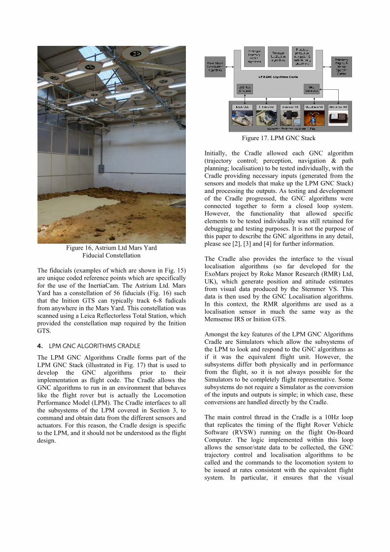
Figure 16, Astrium Ltd Mars Yard
Fiducial Constellation The fiducials (examples of which are shown in Fig. 15) are unique coded reference points which are specifically for the use of the InertiaCam. The Astrium Ltd. Mars Yard has a constellation of 56 fiducials (Fig. 16) such that the Inition GTS can typically track 6-8 fudicals from anywhere in the Mars Yard. This constellation was scanned using a Leica Reflectorless Total Station, which provided the constellation map required by the Inition GTS. 4. LPM GNC ALGORITHMS CRADLE
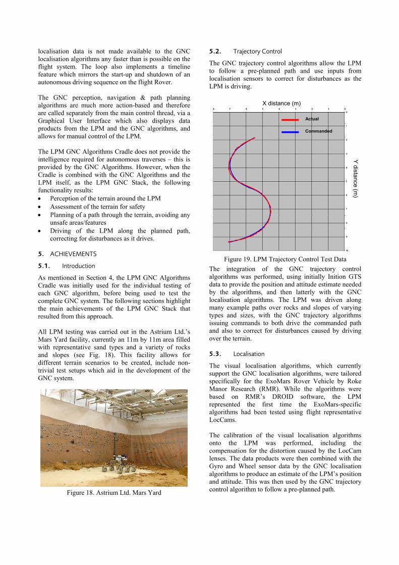
The LPM GNC Algorithms Cradle forms part of the LPM GNC Stack (illustrated in Fig. 17) that is used to develop the GNC algorithms prior to their implementation as flight code. The Cradle allows the GNC algorithms to run in an environment that behaves like the flight rover but is actually the Locomotion Performance Model (LPM). The Cradle interfaces to all the subsystems of the LPM covered in Section 3, to command and obtain data from the different sensors and actuators. For this reason, the Cradle design is specific to the LPM, and it should not be understood as the flight design.
Figure 17. LPM GNC Stack
Initially, the Cradle allowed each GNC algorithm (trajectory control; perception, navigation & path planning; localisation) to be tested individually, with the Cradle providing necessary inputs (generated from the sensors and models that make up the LPM GNC Stack) and processing the outputs. As testing and development of the Cradle progressed, the GNC algorithms were connected together to form a closed loop system. However, the functionality that allowed specific elements to be tested individually was still retained for debugging and testing purposes. It is not the purpose of this paper to describe the GNC algorithms in any detail, please see [2], [3] and [4] for further information. The Cradle also provides the interface to the visual localisation algorithms (so far developed for the ExoMars project by Roke Manor Research (RMR) Ltd, UK), which generate position and attitude estimates from visual data produced by the Stemmer VS. This data is then used by the GNC Localisation algorithms. In this context, the RMR algorithms are used as a localisation sensor in much the same way as the Memsense IRS or Inition GTS. Amongst the key features of the LPM GNC Algorithms Cradle are Simulators which allow the subsystems of the LPM to look and respond to the GNC algorithms as if it was the equivalent flight unit. However, the subsystems differ both physically and in performance from the flight, so it is not always possible for the Simulators to be completely flight representative. Some subsystems do not require a Simulator as the conversion of the inputs and outputs is simple; in which case, these conversions are handled directly by the Cradle. The main control thread in the Cradle is a 10Hz loop that replicates the timing of the flight Rover Vehicle Software (RVSW) running on the flight On-Board Computer. The logic implemented within this loop allows the sensor/state data to be collected, the GNC trajectory control and localisation algorithms to be called and the commands to the locomotion system to be issued at rates consistent with the equivalent flight system. In particular, it ensures that the visual
localisation data is not made available to the GNC localisation algorithms any faster than is possible on the flight system. The loop also implements a timeline feature which mirrors the start-up and shutdown of an autonomous driving sequence on the flight Rover. The GNC perception, navigation & path planning algorithms are much more action-based and therefore are called separately from the main control thread, via a Graphical User Interface which also displays data products from the LPM and the GNC algorithms, and allows for manual control of the LPM. The LPM GNC Algorithms Cradle does not provide the intelligence required for autonomous traverses – this is provided by the GNC Algorithms. However, when the Cradle is combined with the GNC Algorithms and the LPM itself, as the LPM GNC Stack, the following functionality results: Perception of the terrain around the LPM Assessment of the terrain for safety Planning of a path through the terrain, avoiding any
unsafe areas/features Driving of the LPM along the planned path,
correcting for disturbances as it drives. 5. ACHIEVEMENTS
5.1. Introduction
As mentioned in Section 4, the LPM GNC Algorithms Cradle was initially used for the individual testing of each GNC algorithm, before being used to test the complete GNC system. The following sections highlight the main achievements of the LPM GNC Stack that resulted from this approach. All LPM testing was carried out in the Astrium Ltd.’s Mars Yard facility, currently an 11m by 11m area filled with representative sand types and a variety of rocks and slopes (see Fig. 18). This facility allows for different terrain scenarios to be created, include non-trivial test setups which aid in the development of the GNC system.
Figure 18. Astrium Ltd. Mars Yard
5.2. Trajectory Control
The GNC trajectory control algorithms allow the LPM to follow a pre-planned path and use inputs from localisation sensors to correct for disturbances as the LPM is driving.
Actual
Commanded
X distance (m)
Y distance (m
)
Figure 19. LPM Trajectory Control Test Data
The integration of the GNC trajectory control algorithms was performed, using initially Inition GTS data to provide the position and attitude estimate needed by the algorithms, and then latterly with the GNC localisation algorithms. The LPM was driven along many example paths over rocks and slopes of varying types and sizes, with the GNC trajectory algorithms issuing commands to both drive the commanded path and also to correct for disturbances caused by driving over the terrain. 5.3. Localisation
The visual localisation algorithms, which currently support the GNC localisation algorithms, were tailored specifically for the ExoMars Rover Vehicle by Roke Manor Research (RMR). While the algorithms were based on RMR’s DROID software, the LPM represented the first time the ExoMars-specific algorithms had been tested using flight representative LocCams. The calibration of the visual localisation algorithms onto the LPM was performed, including the compensation for the distortion caused by the LocCam lenses. The data products were then combined with the Gyro and Wheel sensor data by the GNC localisation algorithms to produce an estimate of the LPM’s position and attitude. This was then used by the GNC trajectory control algorithm to follow a pre-planned path.

‐3
‐2.5
‐2
‐1.5
‐1
‐0.5
0
‐0.5 0 0.5
Y Distance (m)
X Distance (m)
GroundTruth
VisLocOutput
Figure 20. LPM Visual Localisation Test Data
5.4. GNC System
The LPM uses the Cradle to run all the GNC algorithms in a closed-loop system to reach targets placed up to 9 metres away from it, in scenarios where it was not possible to drive in a straight line from the starting position to the target. Rocks larger than the LPM could surmount were placed in between the starting position and the target, such that the LPM had to drive a non-direct route, stopping several times to re-analyse the terrain and plan a new path. This was achieved successfully, and demonstrated that the different elements of the GNC system could work together coherently.
Figure 21, GNC Terrain Model at Starting Position
TARGET
START
Figure 21. LPM GNC System Test Data
This testing was an important milestone for the ExoMars Rover Vehicle as the GNC algorithms reached Technology Readiness Level 6, well in advance of the Rover Vehicle Delta Preliminary Design Review. 6. CONCULSIONS
This paper has shown that the Locomotion Performance Model is a key element of the model philosophy for the ExoMars Rover Vehicle. It provides all the capabilities, through its suite of sensors and actuators, to allow the GNC algorithms that provide the autonomous traverse intelligence to be developed and tested. The LPM GNC Algorithms Cradle provides the interface between the LPM and the GNC algorithms in such a way that the algorithms run as they would on the flight Rover, which has allowed several important milestones to be reached, in particular the demonstration of the complete closed-loop GNC system in a representative environment. 7. REFERENCES
1. MSA-TRL-ESA(HME)-001. Aurora Use of Technology Readiness Levels, ESA.
2. Silva, N., Lancaster, R. & Clemmet, J. (2013). ExoMars Rover Vehicle Mobility Functional Architecture and Key Design Drivers. ASTRA Conference 2013
3. Lancaster, R., Silva, N., Davies, A. & Clemmet, J. (2013). ExoMars Rover GNC Design and Development. ESA GNC Conference 2011
4. McManamon, K., Lancaster, R. & Silva, N. (2013). ExoMars Rover Vehicle Perception System Architecture & Test Results. ASTRA Conference 2013


![Locomotion [2015]](https://img.dokumen.tips/doc/110x75/55d39c9ebb61ebfd268b46a2/locomotion-2015.jpg)