Embed Size (px)
Citation preview

MicroLogix 1100SELECTION GUIDE
PROGRAMMABLECONTROLLER
1763

MicroLogix 1100 Programmable Controller Selection Guide2
1763-SG001A-EN-P — August 2005

3
1763-SG001A-EN-P — August 2005
MicroLogix 1100 Programmable Controller Selection Guide
MicroLogixFamily Overview
The MicroLogix family of programmable controllers provides four levels of control. Smallon size, big on performance, the MicroLogix 1000 offers control capabilities in anaffordable, compact package. The MicroLogix 1200 is small enough to fit in tight spaces,but powerful enough to accommodate a broad range of applications. Designed to grow asyour needs grow, the MicroLogix 1500 helps you achieve high-level control in a variety ofapplications. The MicroLogix family’s newest member, the MicroLogix 1100, furtherenhances the MicroLogix family by expanding the application coverage area while offeringgreat new features at an affordable price.
MMiiccrrooLLooggiixx 11110000DDeessccrriippttiioonn
The MicroLogix 1100 is our newest family of controllers to join the popular MicroLogix1000, MicroLogix 1200, and MicroLogix 1500 controllers, and is designed to broadenapplication coverage through embedded analog inputs, Ethernet communications andvisualization capabilities. MicroLogix 1100 controllers maintain the same critical featuresyou have come to expect from the MicroLogix family, and expand that capability to includetrue online editing. MicroLogix 1100 controllers complement our low-end controllers forapplications that require up to 80 digital I/O.
Each MicroLogix 1100 contains two embedded analog inputs, with 10 digital inputs and 6digital outputs. The controller may also expand its I/O capabilities using the samemodules as the MicroLogix 1200. Up to four of the 1762 I/O modules can be used with asingle MicroLogix 1100 controller.
Utilizing the latest version of our world class RSLogix 500 programming software, theMicroLogix 1100 controller may be programmed with an instruction set that is commonwith the MicroLogix 1000, MicroLogix 1200, MicroLogix 1500 and SLC 500 families ofcontrollers. RSLogix 500 Starter, Standard, and Professional all support the MicroLogix1100, including its online editing capabilities.
Each controller supports a built-in RS-232 / RS-485 combo port for serial and networkedcommunication and a second built-in EtherNet/IP port, which supports Ethernet peer-to-peer messaging.
An embedded LCD screen allows you to monitor controller and I/O status, as well as makechanges to bit and integer data.
A field-upgradable flash operating system protects your investment and ensures you willalways be up-to-date with the latest enhancements. The controller can be easily updatedwith the latest firmware via a Web site download.

4
1763-SG001A-EN-P — August 2005
MicroLogix 1100 Programmable Controller Selection Guide
AAddvvaannttaaggeess ffoorr tthhee MMiiccrrooLLooggiixx 11110000 CCoonnttrroolllleerrssLarge 8K memory (4K User Program with 4K User Data) to solve a variety of applications
True online editing allows tuning of program, including PID, without going off-line.
Support for MicroLogix 1100 online editing in RSLogix 500 Professional, Standard, and Starter version 7.0 and above.
Mode switch for Run/Remote/Program
Time based or event triggered data logging capability stores controller data records with optional time stamp in a separate 128K bytememory area for later analysis (trending, I/O status during alarm condition, etc.)
Recipe storage (up to 64K bytes that is deducted from Data Logging memory), that is accessible by your ladder program, enabling quickand easy batch changes of program data for timers, counters, etc.
High performance expansion I/O options (up to four 1762 I/O modules, in any combination)
Four high-speed inputs (1763-L16BWA and 1763-L16BBB only) that can be used individually as latching (pulse-catch) inputs, eventinterrupts, or alternately combined as one 20 kHz high-speed counter featuring eight modules of operation
Two built-in 0-10V dc analog inputs with 10 bit resolution (not isolated)
Two high-speed outputs that can be configured as 20 kHz PTO (Pulse Train Output) or as PWM (Pulse Width Modulated) outputs (1763-L16BBB only)
Multiple input commons allow you to use the controller for either sinking or sourcing input devices and multiple output commonsprovide individual isolation in multi-voltage output applications
One, 1 ms, selectable timed interrupt (STI)
High-resolution, 1 ms timers
Communication Channel 0 provides isolated RS-232 or RS-485 electrical compatibility (selectable through the choice of communication cables)

5
1763-SG001A-EN-P — August 2005
MicroLogix 1100 Programmable Controller Selection Guide
Through RS-232, we support DF1 Full Duplex / DF1 Half Duplex Master and Slave / DF1 Radio Modem / ASCII. Additionally, DH-485,Modbus™ RTU Master and Slave are also supported through the 1761-NET-AIC module– see "Through RS-485" below
Through RS-485, we support direct interface to DH-485 and Modbus RTU Master / Slave networks (without an external electricalinterface converter)
Communication Channel 1 consists of an embedded RJ45 port that supports EtherNet/IP for peer-to-peer messaging. This 10/100 Mbpsport supports BOOTP and DHCP
Communications toggle push button that allows the controller's Channel 0 port to toggle between user configured communicationsparameters and factory default settings for an easy means to switch from Modbus RTU or ASCII protocols (which do not supportprogramming) to DF1 Full duplex (to upload / download, monitor, or edit your program), so a programming computer is able to connect toa controller with an unknown or incorrect communication parameter settings for troubleshooting.
Embedded real-time clock
Optional memory module for external program backup, for program transport, and transfer to another controller. Program and data in thecontroller is also battery backed for secure storage.
Data file download protection prevents critical user data from being altered via program downloads from programming computers ormemory modules
Built-in LCD provides access to 48 bits and 48 integers that may be changed, or optionally protected, for monitor only access by anoperator
New LCD instruction allows the controller to output messages to the LCD, and optionally receive user input
IP address can be monitored directly through the built-in LCD
Two built-in digital trim potentiometers
32-bit signed integer math
Floating-point and double integer data file support
Built-in PID capabilities
Finger-safe terminal blocks meet global safety standards
Regulatory agency certifications for world-wide market (CE, C-Tick, UL, c-UL, including Class 1 Division 2 Hazardous Location)

6
1763-SG001A-EN-P — August 2005
MicroLogix 1100 Programmable Controller Selection Guide
OtherMicroLogixFamilyControllersOverview
MMiiccrrooLLooggiixx 11000000DDeessccrriippttiioonn
Based on the architecture of the market-leading SLC 500 controller family, the MicroLogix1000 brings high speed, powerful instructions and flexible communications to applicationsthat demand compact, cost-effective solutions.
The MicroLogix 1000 programmable controller is available in 10-point, 16-point or 32-pointdigital I/O versions. Analog versions are also available with 20 digital I/O points, with 4analog inputs (two voltage and two current) and 1 analog output (configurable for eithervoltage or current).
The analog I/O circuitry for the MicroLogix 1000 units is embedded into the basecontroller, not accomplished through add-on modules. So, it provides very cost-effectiveanalog performance.
The MicroLogix 1000 controller utilizes RSLogix 500 programming software and shares acommon instruction set with the MicroLogix 1100, MicroLogix 1200, MicroLogix 1500 andSLC 500 families of controllers.

7
1763-SG001A-EN-P — August 2005
MicroLogix 1100 Programmable Controller Selection Guide
AAddvvaannttaaggeess ffoorr tthhee MMiiccrrooLLooggiixx 11000000 CCoonnttrroolllleerrssPreconfigured 1K program and data memory to ease configuration (bit, integer, timers, counters, etc.)
Fast processing allows for typical throughput time of 1.5 ms for a 500-instruction program
Built-in EEPROM memory retains all of your ladder logic and data if the controller loses power, eliminating the need for battery back-upor separate memory module
Multiple input commons allow you to use the controller for either sinking or sourcing input devices and multiple output commonsprovide isolation in multi-voltage output applications
RS-232 communication channel allows for simple connectivity to a personal computer for program upload, download and monitoringusing multiple protocols, including DF1 Full Duplex
RTU slave protocol support using DF1 Half-Duplex Slave allows up to 254 nodes to communicate with a single master using radiomodems, leased-line modems or satellite uplinks
Peer-to-peer messaging capability allows you to network up to 32 controllers on a DH-485 network (using a 1761-NET-AIC module)
Advanced communications networks, including DeviceNet and EtherNet/IP through the 1761-NET-DNI and 1761-NET-ENI communicationmodules
Controllers that have 24V dc inputs include a built-in high-speed counter (6.6 kHz)
Adjustable DC input filters allow you to customize the input response time and noise rejection to meet your application needs
Regulatory agency certifications for world-wide market (CE, C-Tick, UL, c-UL, including Class 1 Division 2 Hazardous Location)

8
1763-SG001A-EN-P — August 2005
MicroLogix 1100 Programmable Controller Selection Guide
MMiiccrrooLLooggiixx 11220000DDeessccrriippttiioonn
The MicroLogix 1200 controllers provide more computing power and greater I/O flexibilitythan the MicroLogix 1000 to solve a variety of application needs.
Available in 24 and 40-point versions, the I/O count can be expanded using rackless I/Omodules. This results in larger control systems, greater application flexibility andexpandability at a lower cost and reduced parts inventory.
A field-upgradable flash operating system ensures you will always be up-to-date with thelatest features, without having to replace hardware. The controller can be easily updatedwith the latest firmware via a web site download.
Building on the features of the MicroLogix 1000, the MicroLogix 1200 also has additionaladvantages.

9
1763-SG001A-EN-P — August 2005
MicroLogix 1100 Programmable Controller Selection Guide
AAddvvaannttaaggeess ffoorr tthhee MMiiccrrooLLooggiixx 11220000 CCoonnttrroolllleerrssLarge 6K memory (4k User Program with 2K User Data) to solve a variety of applications
High performance expansion I/O options (up to 6 modules depending on current / power budget)
Four high-speed inputs (for controllers with 24V dc inputs) that can be used individually as latching (pulse-catch) inputs, event interrupts,or alternately combined as one 20 kHz high-speed counter featuring eight modes of operation
One high-speed output that can be configured as 20 kHz PTO (Pulse Train Output) or as PWM (Pulse Width Modulated) output (availableon controllers with embedded 24V dc outputs)
One, 1 ms, selectable timed interrupt (STI)
High-resolution, 1 ms timers
The same advanced communications options as the MicroLogix 1000, including peer-to-peer and SCADA/RTU networks, DF1 Full Duplex,DF1 Half Duplex Slave, DH-485, DeviceNet and EtherNet/IP , plus DF1 Half Duplex Master, Modbus Master and Slave, and DF1 RadioModem protocols
ASCII read / writes
An additional Programming / HMI Port, providing connectivity to a DF1 Full Duplex compatible device such as an operator interface orprogramming terminal (MicroLogix 1200R only, 1762-LxxxxxR controllers)
Communications toggle push button that allows the controller's Channel 0 port to toggle between user configured communicationsparameters and factory default settings for an easy means to switch from Modbus RTU or ASCII protocols (which do not supportprogramming) to DF1 Full duplex (to upload / download, monitor, or edit your program), so a programming computer is able to connect toa controller with an unknown or incorrect communication parameter settings for troubleshooting.
Optional real-time clock, to allow control to be based on actual time of day, day of week, or other calendar related timing.
Optional memory module, for external program backup, transport and transfer to another controller. Control program and data aresecurely backed up to internal flash memory when power is not applied.
Data file download protection prevents critical user data from being altered via program downloads from programming computers ormemory modules
Two built-in analog trim potentiometers
32-bit signed integer math
Floating-point and double integer data file support
Built-in PID capabilities
Finger-safe terminal blocks meet global safety standards
Removable terminal blocks on 40-point controllers allow pre-wiring
Regulatory agency certifications for world-wide market (CE, C-Tick, UL, c-UL, including Class 1 Division 2 Hazardous Location)

10
1763-SG001A-EN-P — August 2005
MicroLogix 1100 Programmable Controller Selection Guide
MMiiccrrooLLooggiixx 11550000DDeessccrriippttiioonn
The MicroLogix 1500 is a world-class programmable logic control platform with even moreadvanced features and performance than the MicroLogix 1200. Many of these featuresallow this controller to be used in applications where much larger controllers wererequired in the past.
MicroLogix 1500 architecture features an innovative two-piece design with a smallfootprint. The processor and base units slide together to form the complete controller. Theprocessor and base are independently replaceable, allowing you to maximize yourembedded I/O, memory, and communication options while minimizing inventory stocking costs.
Bulletin 1769 Compact I/O modules expand the controller's embedded I/O offerings andprovide the additional flexibility to cover a wide range of applications. This high-performance modular and rackless I/O platform provides front accessibility for removaland insertion. Removable terminal blocks further lower the total system cost by reducingstart-up and maintenance time.
New features are provided with an enhanced user interface that uses function files toconsolidate programming parameters. This simplifies the user interface and increasescontroller performance.
The MicroLogix 1500 includes all the features of the MicroLogix 1200, plus more.

11
1763-SG001A-EN-P — August 2005
MicroLogix 1100 Programmable Controller Selection Guide
AAddvvaannttaaggeess ffoorr tthhee MMiiccrrooLLooggiixx 11550000 CCoonnttrroolllleerrss ((iinn aaddddiittiioonn ttoo MMiiccrrooLLooggiixx 11220000 ffeeaattuurreess))
Large memory to solve a variety of applications.1764-LSP: 7K user program capacity (3.65K User Program with 4K User Data)1764-LRP: 14K user program capacity (10K User Program with 4K User Data)
Mode switch for Run / Remote / Program
MicroLogix 1500 controllers using the 1764-LRP processor, can perform time based or event triggered data logging. This allows thecontroller to store data records with optional time stamp in a separate 48K byte memory area for later analysis (trending, I/O statusduring alarm condition, etc.)
Recipe storage (up to 48K bytes that is deducted from Data Logging memory), that is accessible by your ladder program, enabling quickand easy batch changes of program data for timers, counters, etc.
High performance expansion I/O options (up to 16 modules using an additional bank of expansion I/O and expansion power supply)
There is an additional Channel 1 configurable isolated RS-232 communications port on the 1764-LRP processor
Battery for non-volatile user program and user data (built-in and optional replacement)
Optional data access tool (1764-DAT) allows a user to change integer and bit values within the controller, or optionally protect theseelements for monitor only.
Eight high-speed inputs (for controllers with 24V dc inputs) that can be used individually as latching (pulse-catch) inputs, eventinterrupts, or alternately combined in groups of four (0 through 3, and 4 through 7) as two 20 kHz high-speed counter featuring eightmodes of operation
Two high-speed output that can be configured as 20 kHz PTO (Pulse Train Output) or as PWM (Pulse Width Modulated) output (availableon controllers with embedded 24V dc outputs)
Removable terminal blocks on all MicroLogix 1500 Base Units and I/O modules enable pre-wiring

12
1763-SG001A-EN-P — August 2005
MicroLogix 1100 Programmable Controller Selection Guide
MicroLogixSystem SelectionChecklist
Use the following Checklist as a guide to completing your own system specification. Skipany sections that do not apply.
SStteepp SSeeee
1 Select Controller Family: MicroLogix 1000, 1100, 1200 or 1500controller family - based on memory, I/O, required control functionality, and dimensionsconsider future expansion requirementsconsider requirement for online editingconsider the need for networked communicationsif selecting the MicroLogix 1000, 1200 or 1500, see 1761-SG001 (MicroLogixProgrammable Controllers Family Selection Guide)
page 13
2 Select MicroLogix Communication Interface Devicescommunication network - based on application requirementsrecord your selection in the Selection Record (starts on page 39 )
page 19
3 Select Programming Softwaresoftware - the appropriate RSLogix 500 package for your applicationrecord your selection in the Selection Record (starts on page 39 )
page 25
4 Select Cablescables - review device port identification to find cable in the selection chartrecord your selection in the Selection Record (starts on page 39 )
page 26
5 Select MicroLogix 1100 Controllers and Accessoriescontroller - review power and I/O configurations to select a controller catalog number; seepower supply and I/O specifications for more detailed informationaccessories - memory modulerecord your selection in the Selection Record (starts on page 39 )
page 29
6 Select MicroLogix 1100 Expansion I/OI/O modules - digital, analog and temperaturerecord your selection in the Selection Record (starts on page 39 )
page 33
7 Fill in Your Selection Listingall catalog numbers required for your system specification page 39

13
1763-SG001A-EN-P — August 2005
MicroLogix 1100 Programmable Controller Selection Guide
Select ControllerFamily:MicroLogix 1000, 1100,1200 or 1500Step 1 - Select:
Review the Features, Programming Instructions, Controller Specifications and ControllerDimensions to determine which level of MicroLogix controller is required.
FFeeaattuurreessMMiiccrrooLLooggiixx 11000000,, 11110000,, 11220000 aanndd 11550000 FFeeaattuurree CCoommppaarriissoonn CChhaarrtt
controller family - based on memory, I/O,added functionality, programminginstructions and dimensions
consider future expansion requirements
consider requirement for online editing
consider the need for networkedcommunications
if selecting the MicroLogix 1000,MicroLogix 1200 or MicroLogix 1500,see 1761-SG001 (MicroLogixProgrammable Controllers SelectionGuide), for more information.
CCoonnttrroolllleerrBBuulllleettiinn NNuummbbeerr
Up to 1K
Up to 6K
Up to 7K
Up to 8K
Up to 14K
Online editing
Non-volatile program and data
Memory Module (for program back-upand transport)
Embedded digital I/O (max.)
Embedded analog I/O
Local Expansion I/O (max.)
Thermocouple / RTD
Networked Expansion I/O
Trim Potentiometers
PID
High Speed Counters (embedded)
High Speed Counters (expansion)
Motion: Pulse Width Modulated orPulse Train Outputs for use with stepperor servos
MMiiccrrooLLooggiixx 11000000
MMiiccrrooLLooggiixx 11110000
MMiiccrrooLLooggiixx 11220000 //11220000RR
MMiiccrrooLLooggiixx 11550000 11776644--LLSSPP // 11776644--LLRRPP
11776611 11776633 11776622 11776644MMeemmoorryy ((iinn uusseerr wwoorrddss)) UUsseerr PPrrooggrraamm // UUsseerr DDaattaa
1K combined(preconfigured)
4K / 2K
3.6K / 4K 1764-LSP
4K / 4K
10K / 4K 1764-LRP
EEPROM Battery back-upstatic RAM Flash Battery back-up static RAM
through hand-heldprogrammer Optional Optional Optional
II//OO32 16 40 28
Two current andtwo voltage inputswith one current orvoltage output on20 pt. controllers
Two 0 - 10V dcinputs on allcontrollers
none 64 96 512
Expansion Expansion Expansion
none none none
DeviceNet using 1769-SDNscanner can own 63 slavedevices (such as a 1769-ADNwith up to 30 I/O modules per1769-ADN)
AAddddeedd FFuunnccttiioonnaalliittyyTwo (digital) 2 2
One @ 6.6 kHz One @ 20 kHz One @ 20 kHz Two @ 20 kHz
with 1769-HSCTwo quadrature or fourpulse/count @ 1 MHz
Two @ 20 kHz One @ 20 kHz Two @ 20 kHz

14
1763-SG001A-EN-P — August 2005
MicroLogix 1100 Programmable Controller Selection Guide
MMiiccrrooLLooggiixx 11000000,, 11110000,, 11220000 aanndd 11550000 FFeeaattuurree CCoommppaarriissoonn CChhaarrtt
CCoonnttrroolllleerrMMiiccrrooLLooggiixx 11000000
MMiiccrrooLLooggiixx 11110000
MMiiccrrooLLooggiixx 11220000 // 11220000RR
MMiiccrrooLLooggiixx 11550000 11776644--LLSSPP // 11776644--LLRRPP
BBuulllleettiinn NNuummbbeerr 11776611 11776633 11776622 11776644Real Time Clock Embedded Optional Optional
Data Access Tool Optional
LCD: monitor I/O andcontroller status / dataadjustment
Embedded
Data Logging Up to 128Kb Up to 48Kb, 1764-LRP
Recipe (uses data logging memory) Up to 68Kb
Up to 48Kb, 1764-LRP(1764-LSP can useprogram memory)
Floating Point Math
ASCII Data File
PPrrooggrraammmmiinngg
Windows - RSLogix 500Software
Hand-Held Programmer
CCoommmmuunniiccaattiioonnss
Serial Ports One RS-232 8-pinmini DIN
One isolated RS-232/ RS-485 combo 8-pin mini DIN
(1) 8-pin mini DIN 1200controllers(1) 8-pin mini DIN & (1) 8-pin mini DIN Programming /HMI only port1200R controllers
(1) 8-pin mini DIN 1764-LSP processors(1) 8-pin mini DIN & (1)isolated 9-pin D-shell,1764-LRP processors
Ethernet Ports One 10/100 MbpsRJ-45
DeviceNet peer-to-peermessaging / Slavefunctionality
with 1761-NET-DNI with 1761-NET-DNI with 1761-NET-DNI with 1761-NET-DNI
DeviceNet Scanner, withMaster and Peer-to-Peercomms
with 1769-SDN (1764-LRP only)
EtherNet/IP Peer-to-PeerMessaging
with 1761-NET-ENIor 1761-NET-ENIW
Embedded or w/1761-NET-ENI or1761-NET-ENIW
with 1761-NET-ENIor 1761-NET-ENIW
with 1761-NET-ENIor 1761-NET-ENIW
Web Server Capabilities with 1761-NET-ENIW
Embedded or w/1761-NET-ENIW with 1761-NET-ENIW with 1761-NET-ENIW
DH-485 Networking with 1761-NET-AIC Embedded with 1761-NET-AIC with 1761-NET-AIC
SCADA RTU - DF1 Half-Duplex Slave only Master / Slave Master / Slave Master / Slave
SCADA RTU - DF1 RadioModem
SCADA RTU - Modbus RTU Master / Slave Master / Slave Master / Slave
ASCII - Read/Write
OOppeerraattiinngg PPoowweerr120/240V ac
24V dc
AAggeennccyy CCeerrttiiffiiccaattiioonnss
CE, C-Tick, UL and C-UL(including Class 1, Division 2for Hazardous Location)

15
1763-SG001A-EN-P — August 2005
MicroLogix 1100 Programmable Controller Selection Guide
PPrrooggrraammmmiinngg IInnssttrruuccttiioonnssMicroLogix controllers have the range of functionality necessary to address diverseapplications. The controllers use the following types of instructions:
Basic Instructions (i.e., Examine if On, Examine if Off)
Data Comparison Instructions (i.e., Equal, Greater than or Equal, Less than or Equal)
Data Manipulation Instructions (i.e., Copy, Move)
Math Instructions (i.e., Add, Subtract, Multiply)
Program Flow Control Instructions (i.e., Jump, Subroutine)
Application Specific Instructions (i.e., Programmable Limit Switch, Sequencer)
High-Speed Counter Instruction
High-Speed PTO (Pulse Train Output) and PWM (Pulse Width Modulated) Instructions (forMicroLogix 1100, 1200 and 1500 only)
Communication Instruction (including ASCII for MicroLogix 1100, 1200, and 1500 only)
Recipe Instruction (MicroLogix 1100 and 1500 only)
Data Logging Instruction (MicroLogix 1100 and 1500 1764-LRP processor only)
LCD Instruction (MicroLogix 1100 only)

16
1763-SG001A-EN-P — August 2005
MicroLogix 1100 Programmable Controller Selection Guide
CCoonnttrroolllleerr SSppeecciiffiiccaattiioonnss ffoorr MMiiccrrooLLooggiixx 11110000 CCoonnttrroolllleerrssCCoonnttrroolllleerr GGeenneerraall SSppeecciiffiiccaattiioonnss
EEnnvviirroonnmmeennttaall SSppeecciiffiiccaattiioonnss aanndd CCeerrttiiffiiccaattiioonnss
SSppeecciiffiiccaattiioonn 11776633 CCoonnttrroolllleerrssOperating Temperature -20…65 °C (-4…149 °F)
Storage Temperature -40…85 °C (-40…185 °F)
Relative Humidity 5…95% non-condensing
Vibration Operating: 10…500 Hz, 5 g, 0.015 in max. peak-to-peak (Relay Operation: 1.5 g)
Shock, Operating 30 g; 3 pulses each direction, each axis (Relay Operation: 10 g)
Shock, Non-Operating 50 g panel mounted (40 g Din Rail mounted); 3 pulses each direction, each axis
Certifications
UL Listed Industrial Control Equipment for use in class 1, Division 2, Hazardous Locations, Groups A, B, C, D
C-UL Listed Industrial Control Equipment for use in Canada
CE marked for all applicable directives
C-Tick marked for all applicable acts
Electrical/EMC The controller has passed testing at the following levels
ESD Immunity EN 61000-4-24 kV contact, 8 kV air, 4 kV indirect
Radiated Immunity ENV 5020410V/m, 1000 MHz
Radiated RF Immunity EN 61000-4-310V/m, 26…1000 MHz (alternatively, 80…1000 MHz), 80% amplitude modulation, +900 MHz keyed carrier
EFT/B ImmunityEN 61000-4-4Power Supply, I/O: 2 kV , 5 kHzCommunications Cable: 1 kV , 5 kHz
Surge TransientImmunity
EN 61000-4-5Unshielded Communications Cable: 2 kV CM (common mode), 1 kV DM (differential mode)Shielded Communications Cable: 1 kV galvanic gunI/O: 2 kV CM (common mode), 1 kV DM (differential mode)AC Power Supply: 4 kV CM (common Mode), 2 kV DM (differential mode)DC Power Supply: 500V CM (common mode), 500V DM (differential mode)AC/DC Auxiliary Output: 500V CM (common mode), 500V DM (differential mode)
Conducted RFImmunity
EN 61000-4-6Power Supply, I/O: 10V, 150 kHz…80 MHz
Conducted Emissions EN 55011AC Power Supply Input: 150 kHz…30 MHz
Radiated Emissions EN 5501130 MHz…1000 MHz
Line Related Tests
EN 61000-4.11AC Power Supply Input:
voltage drop: -30% for 10 ms, -60% for 100msvoltage interrupt: at voltage greater than -95% for 5 sec.voltage fluctuation: +10% for 15 minutes
DC Power Supply Inputvoltage fluctuation: +20% for 15 minutes, -20% for 15 minutes
SSppeecciiffiiccaattiioonnMMiiccrrooLLooggiixx 11110000((BBuulllleettiinn 11776633))
User Program and Data Memory8K battery backed RAM: 4K user program, 4K user data
Data Elements configurable, user defined file structure, 4Kmax. data size

17
1763-SG001A-EN-P — August 2005
MicroLogix 1100 Programmable Controller Selection Guide
CCoonnttrroolllleerr DDiimmeennssiioonnss
Dimensions are in millimeters (inches).
Controller spacing = 50 mm (2 in) on all sides for adequate ventilation.
MMiiccrrooLLooggiixx 11110000 CCoonnttrroolllleerr DDiimmeennssiioonn DDrraawwiinngg
C
BA
MMiiccrrooLLooggiixx 11110000 CCoonnttrroolllleerr DDiimmeennssiioonnss
DDiimmeennssiioonnA
B
C
11776633--LL1166AAWWAA,, 11776633--LL1166BBWWAA,, 11776633--1166BBBBBB90 mm (3.5 in)
110 mm (4.33 in)
87 mm (3.43 in)
1763-L16AWA, 1763-L16BWA, 1763-L16BBB

18
1763-SG001A-EN-P — August 2005
MicroLogix 1100 Programmable Controller Selection Guide
11776622 EExxppaannssiioonn II//OO DDiimmeennssiioonnss
A
B
C
DDiimmeennssiioonnA
B
C
EExxppaannssiioonn II//OO MMoodduullee90 mm (3.5 in)
40 mm (1.57 in)
87 mm (3.43 in)
CCoonnttrroolllleerr SSppaacciinnggThe controller mounts horizontally, with the expansion I/O extending to the right of thecontroller. Allow 50 mm (2 in) of space on all but the right side for adequate ventilation, as shown below.
ESC OK
DDIINN RRaaiill MMoouunnttiinnggThe maximum extension of the latch is 14 mm (0.55 in) in the open position. A flat-bladescrewdriver is required for removal of the controller. The controller can be mounted toEN50022-35 x 7.5 or EN50022-35 x 15 DIN rails. DIN rail mounting dimensions are shown below.
A
B
C
DDiimmeennssiioonn HHeeiigghhttA 90 mm (3.5 in)
B 27.5 mm (1.08 in)
C 27.5 mm (1.08 in)

19
1763-SG001A-EN-P — August 2005
MicroLogix 1100 Programmable Controller Selection Guide
SelectMicroLogixCommunicationInterface DevicesStep 2 - Select:
communication network - based onapplication requirements
record your selection in the SelectionRecord (starts on Page 39)
CCoommmmuunniiccaattiioonn NNeettwwoorrkkssMicroLogix controllers allow you to choose the network that best meets your needs.
Note: The MicroLogix 1100 controller does not provide 24V dc power for network interfacewhereas all other MicroLogix controllers do. The 24V dc comms power must be providedexternally when 1761-NET-AIC or 1761-NET-ENI or 1761-NET-ENIW modules are used witha MicroLogix 1100 controller. MicroLogix 1100 controllers provide direct connection to RS-485 networks using the same pins used by the other MicroLogix controllers for 24V dccommunication power.
Channel 0 Isolated RS-232 / RS-485 Combo port
For RS-232 communications:
− 300; 600; 1200; 4800; 9600; 19.2K and 38.4K baud rates
− RTS/CTS hardware handshake signals
− Connection to DH-485, DeviceNet and Ethernet networks through the 1761-NET-AIC,1761-NET-DNI and 1761-NET-ENI interface modules, respectively (MicroLogix 1100controllers also connect to DH-485 directly through 1763-NC01 cable to Channel 0and to Ethernet networks directly through Channel 1. MicroLogix 1500 controllers alsoprovide DeviceNet Master capability via the 1769-SDN DeviceNet Scanner Module)
− Connection to modems for remote communications
− ASCII messaging provides dial-out capability
− DF1 Half-Duplex Slave
− DF1 Full-Duplex Master
− Modbus RTU Master / Slave through the 1761-NET-AIC module ( MicroLogix 1100controllers also connect to Modbus RTU Master / Slave directly through 1763-NC01cable to Channel 0)

20
1763-SG001A-EN-P — August 2005
MicroLogix 1100 Programmable Controller Selection Guide
MMiiccrrooLLooggiixx NNeettwwoorrkk OOppttiioonnss ((RRSS--223322 uunnlleessss ootthheerrwwiissee nnootteedd))
IIff yyoouurr aapppplliiccaattiioonn rreeqquuiirreess:: UUssee tthhiiss nneettwwoorrkk::Connection to dial-up modems for remote programmaintenance or data collectionConnection to leased-line or radio modems for use inSCADA systemsRemote Terminal Unit (RTU) functionsProgram upload, download and monitoring
DF1 Full-DuplexDF1 Half-Duplex SlaveDF1 Radio Modem
Plant-wide and cell-level data sharing with programmaintenanceData sharing between 32 controllersPeer-to-peer communicationProgram upload, download and monitoringCompatibility with multiple Allen-Bradley HMI devices
DH-485 directly through channel 0 RS-485 port using 1763-NC01 cableDH-485 via the 1761-NET-AIC Advanced Interface Converter or1747-UIC USB to DH-485 Converter
Data sharing between 64 devicesBetter diagnostics for improved data collection and faultdetectionLess wiring and reduced start-up time than traditional, hard-wired systemsProgram upload, download and monitoringPeer-to-peer communication
DeviceNet via the 1761-NET-DNI DeviceNet Interface
Program upload, download and monitoringPeer-to-peer communicationEmail communication10/100Base-T port with embedded LEDSWeb server capability via the 1761-NET-ENIW
EtherNet/IP directly through Channel 1 10/100 Mbpscommunication portEtherNet/IP via the 1761-NET-ENI Ethernet Interface or1761-NET-ENIW Web enabled Ethernet Interface
Connection to third party devices for remote data collectionin a SCADA system (i.e., telephone modems, radio modems,leased lines, etc.)Remote Terminal Unit (RTU) functions
Modbus RTU Master / Slave directly through channel 0 RS-485port using 1763-NC01 cableModbus RTU Slave via the 1761-NET-AIC Advanced InterfaceConverter Modbus RTU Master via the 1761-NET-AIC Advanced InterfaceConverter
MicroLogix 1100 controllers do not provide 24V dc power for network interface devices. External 24V dc module power must be supplied.Direct EtherNet/IP connections through MicroLogix 1100 controllers provide web server capabilities but do not support email communications.

21
1763-SG001A-EN-P — August 2005
MicroLogix 1100 Programmable Controller Selection Guide
MMiiccrrooLLooggiixx NNeettwwoorrkk IInntteerrffaaccee DDeevviicceess
The following information describes the functionality of the MicroLogix Interface Modules.For most applications, the embedded RS-485 and Ethernet / IP functionality of theMicroLogix 1100 communication ports replaces the 1761-NET-AIC, 1761-NET-ENI, and the1761-NET-ENIW (or AIC+, ENI, and ENIW) modules.
The network interface devices can be mounted on a panel or DIN rail. See NetworkInterface Devices Communication Port Identification on page 24 for device drawings.
AAIICC++ AAddvvaanncceedd IInntteerrffaaccee CCoonnvveerrtteerr ((11776611--NNEETT--AAIICC))
The AIC+ is an isolated, RS-232 to RS-485 electrical signal converter for supporting serial,half-duplex, multi-drop protocols; such as:
DH-485
DF1 Half-Duplex Master/Slave
Modbus RTU (a single master can communicate with a maximum of 247slave devices)
Since RS-232 ports can only be connected point-to-point between two devices, an AIC+ (orsimilar device) is required whenever a MicroLogix controller is configured for one of theseprotocols and needs to communicate with more than one other device at a time. The AIC+also provides electrical isolation between each of its three ports for a more stablenetwork and protection for connected devices.
When using the 1763-NC01 cable, the MicroLogix 1100 provides isolated connection toRS-485 networks directly from the Channel 0 combo port.
Any MicroLogix controller can connect to either of the two RS-232 ports on the AIC+.When Channel 0 on a MicroLogix 1000, 1200, or 1500 controller is connected to Port 2(RS-232 8-pin mini-DIN) of the AIC+, the Interface Module can draw its power from theMicroLogix controller. In all other cases, including utilizing MicroLogix 1100 controllers,the AIC+ must be powered from an external, 24V dc power supply. The AIC+ can also beused as an RS-232 to RS-485 converter and port isolator for any other Allen-Bradleycontroller or terminal with an RS-232 port.
Since the AIC+ is not a protocol converter, all devices connected to a single AIC+ (or anetwork of AIC+s) must be configured for the same communication protocol.
DDHH--448855//RRSS--448855 NNeettwwoorrkk SSppeecciiffiiccaattiioonnss
SSppeecciiffiiccaattiioonn 11776611--NNEETT--AAIICCMaximum Number of Nodes 32 per multi-drop network
Maximum Length 1219 m (4,000 ft) per multi-drop network

22
1763-SG001A-EN-P — August 2005
MicroLogix 1100 Programmable Controller Selection Guide
DDNNII DDeevviicceeNNeett IInntteerrffaaccee ((11776611--NNEETT--DDNNII))
DNI capabilities:
DDeevviicceeNNeett SSppeecciiffiiccaattiioonnss
SSppeecciiffiiccaattiioonn 11776611--NNEETT--DDNNIIMaximum Number of Nodes 64
Maximum Length 500 m @ 125K baud or 100 m @ 500K baud
DeviceNet Agency Certification ODVA conformance 2.0-A12
Peer-to-peer messaging between Allen-Bradley controllers and other devices using theDF1 Full-Duplex protocol
Programming and online monitoring over the DeviceNet network
With a DNI connected to a modem, you can dial in to any other DNI-controllercombination on DeviceNet
Other DeviceNet products can send explicit (Get or Set) messages with the DNI at any time
The controller can initiate an explicit message to a UCMM (Unconnected MessageManager) compatible device on DeviceNet

23
1763-SG001A-EN-P — August 2005
MicroLogix 1100 Programmable Controller Selection Guide
The following information describes the functionality of the MicroLogix InterfaceConverter Modules.
EENNII EEtthheerrnneett IInntteerrffaaccee ((11776611--NNEETT--EENNII)) aanndd EENNIIWWEEtthheerrnneett IInntteerrffaaccee wwiitthh WWeebb SSeerrvveerr CCaappaabbiilliittiieess((11776611--NNEETT--EENNIIWW))
The ENI provides EtherNet/IP connectivity for all MicroLogix controllers and other DF1Full-Duplex devices. The ENI allows you to easily connect a MicroLogix controller to a newor existing Ethernet network to update/download programs, communicate betweencontrollers and generate email messages via SMTP (simple mail transport protocol).
The ENIW adds web server capabilities, enabling the display of four standard data webpages with user-configurable data descriptions and 10 user-configurable web page linkson the ENIW home page.
MicroLogix 1100 controllers also provide EtherNet/IP connectivity and Web servercapabilities directly through Channel 1 but do not support email communications (in thePhase 1 release).
EEtthheerrnneett SSppeecciiffiiccaattiioonnss
SSppeecciiffiiccaattiioonn 11776611--NNEETT--EENNIICommunication Rate 10/100 MHz (Series C), 10 MHz (Series A and B)
Connector 100Base-T (Series C), 10Base-T (Series A and B)

24
1763-SG001A-EN-P — August 2005
MicroLogix 1100 Programmable Controller Selection Guide
SSppeecciiffiiccaattiioonnss 11776611--NNEETT--AAIICC 11776611--NNEETT--DDNNII 11776611--NNEETT--EENNII,, 11776611--NNEETT--EENNIIWWPower Supply DC Voltage Range 20.4…28.8V dc 11…25V dc 20.4…26.4V dc
Current Draw (mA) at 24V dc 120 mA 200 mA 50 mA
Inrush Current, Max. 200 mA @ 24V 400 mA @ 24V 200 mA @ 24V
Isolation Voltage 500V dc for one minute 500V dc for 1 minute 710V dc for one minute
Operating Temperature 0…60 °C (32…140 °F)
Storage Temperature -40…85 °C (-40…185 °F)
Relative Humidity 5…95% non-condensing
Vibration Operating: 10…500 Hz, 5.0 g, 0.030 in. peak-to-peak, 2 hour each axis
Operating: 5…2000 Hz, 2.5 g, 0.015 in. peak-to-peak, 1 hour each axisNon-operating: 5…2000 Hz, 5.0g, 0.030 in. peak-to-peak, 1 hour each axis
Operating: 10…500 Hz, 5.0 g, 0.030 in. peak-to-peak, 2 hour each axis
Shock, Operating 30 g, ±3 times each axis 30 g, ±3 times each axis 30 g, ±3 times each axis
Shock, Non-Operating 50 g, ±3 times each axis 50 g, ±3 times each axis 35 g (DIN rail mount) 50 g (panel mount) ±3 timeseach axis
Certifications
UL Listed Industrial Control Equipment for use in Class 1, Division 2, Hazardous Locations, Groups A, B, C, D.
c-UL Listed Industrial Control Equipment for use in Canada.
CE marked for all applicable directives.
C-Tick marked for applicable acts.
When the device is connected to a MicroLogix 1000, 1200, or 1500 controller, power is provided by the MicroLogix controller's communication port. Power is not supplied by the MicroLogix 1100 controllers. External 24V dcmodule power must be supplied.
AAIICC++,, DDNNII aanndd EENNII//EENNIIWW SSppeecciiffiiccaattiioonnss
NNeettwwoorrkk MMoodduulleess SSppeecciiffiiccaattiioonnss
AAIICC++,, DDNNII aanndd EENNII//EENNIIWW DDiimmeennssiioonnss
NNeettwwoorrkk IInntteerrffaaccee DDeevviicceess DDiimmeennssiioonnss
Allow 15 mm (0.6 in) for
27.7 mm
107 mm118 mm
52.07 mm
6.6 mm
64.8 mm
71.4 mm
(2.05 in)
(4.64 in)
(1.09 in)
(4.20 in)
(2.81 in) AIC+ only
(2.55 in)
AIC+ only(0.26 in)
during installation and removal.DIN rail latch movement

25
1763-SG001A-EN-P — August 2005
MicroLogix 1100 Programmable Controller Selection Guide
SelectProgrammingSoftwareStep 3 - Select:
software - the appropriate RSLogix 500package for your application
record your selection in the SelectionRecord (starts on page 39)
PPrrooggrraammmmiinngg SSooffttwwaarree
The RSLogix 500 ladder logic programming package helps you maximize performance,save project development time and improve productivity. This product has been developedto operate on Windows® operating systems. RSLogix 500 can be used for programmingboth the SLC 500 and MicroLogix controller families.
RRSSLLooggiixx 550000 SSeelleeccttiioonn CChhaarrtt
CCaatt.. NNoo.. DDeessccrriippttiioonn
9324-RL0100ENERSLogix 500 Starter EditionProgramming Software for MicroLogixcontroller families. (CD-ROM)
9324-RL0300ENE
RSLogix 500 Standard EditionProgramming Software for SLC 500and MicroLogix controller families.(CD-ROM)
9324-RL0700NXENE
RSLogix 500 Professional Edition. CD-ROM also includes RSLogix Emulate500, RSNetWorx for DeviceNet andRSNetWorx for ControlNet.

26
1763-SG001A-EN-P — August 2005
MicroLogix 1100 Programmable Controller Selection Guide
Select CablesStep 4 - Select:
cables - review device port identificationto find cable in the selection chart
record your selection in the SelectionRecord (starts on page 39)
Cables come in several lengths and connector styles to provide connectivity betweenMicroLogix controllers and other devices.
NNeettwwoorrkk CCaabbllee SSeelleeccttiioonnCCoonnttrroolllleerr aanndd PPCC PPoorrtt IIddeennttiiffiiccaattiioonn
DDeevviiccee CCoommmmuunniiccaattiioonn PPoorrtt DDeessccrriippttiioonn CCoonnnneeccttoorr TTyyppee
MicroLogix 1100
RS-232/RS-485 Communications Port (Channel 0, no24V dc power for communication Interface Modules) 8-pin Mini DIN
10/100Mbps EtherNet/IP Communications Port (Channel 1) RJ-45
Personal ComputerPersonal Computer Serial Communications Port 9-pin D Shell
Personal Computer Ethernet Communications Port RJ-45
NNeettwwoorrkk IInntteerrffaaccee DDeevviicceess CCoommmmuunniiccaattiioonn PPoorrtt IIddeennttiiffiiccaattiioonn
NODE
DANGER
GND
TX/RX
V±
CAN_L
SHIELDCAN_H
V+
NET
MOD
ETHERNET
FAULT
RS232
NET
TX/RXTX/RX
PWR
CABLE
EXTERNAL
IP
AIC+ DNI ENI/ENIW
DH-485
RS-232
DeviceNet
RS-232Ethernet
9-PIn D Shell
8-PIn Mini DIN
8-PIn Mini DINRS-232
8-PIn Mini DINRS-232

27
1763-SG001A-EN-P — August 2005
MicroLogix 1100 Programmable Controller Selection Guide
NNeettwwoorrkk CCaabbllee SSeelleeccttiioonn CChhaarrtt
PPrrooggrraammmmiinngg CCaabblleeSSeelleeccttiioonnPPrrooggrraammmmiinngg CCaabbllee SSeelleeccttiioonn CChhaarrtt -- PPrrooggrraammmmiinngg DDeevviiccee ttoo CCoonnttrroolllleerr
MMiiccrrooLLooggiixx 11110000CChhaannnneell 00 ((88--ppiinn MMiinnii DDIINN))
MMiiccrrooLLooggiixx 11110000CChhaannnneell 11 ((RRJJ--4455))PPrrooggrraammmmiinngg
DDeevviiccee CCaatt.. NNoo.. LLeennggtthh CCaatt.. NNoo.. LLeennggtthhPersonal Computer (9-pinD Shell)
1761-CBL-PM02 (Series C or laterfor Class I Div 2 applications) 2 m (6.5 ft) ⎯ ⎯
Personal Computer (RJ-45) ⎯ ⎯ Ethernet Cable(Commercially available)
100 m (328 ft)maximum
11774477--UUIICC UUnniivveerrssaall SSeerriiaall BBuuss ttoo DDHH--448855 IInntteerrffaaccee CCoonnvveerrtteerrThis device allows a computer with a USB port to interface to DH-485 ports on an SLC500, MicroLogix, or other Rockwell Automation controllers and on PanelView terminals.The 1747-UIC features a USB connector as well as both an RS-232 and an RS-485 port.Use the RS-232 port to connect to SLC 5/03, 5/04, 5/05 (Channel 0), MicroLogix,CompactLogix, FlexLogix, ControlLogix, PanelView 300 or higher, or AIC+. Use the RS-485Port to connect to SLC 5/01, 5/02, 5/03 (Channel 1), PanelView 300 or higher, or 1747-AIC.
UUSSBB ttoo DDHH--448855 IInntteerrffaaccee CCoonnvveerrtteerr SSppeecciiffiiccaattiioonnss
CCaatt.. NNoo..USB Power Consumption
USB Speed
DH-485 Baud Rate
11774477--UUIICC<100 mA (low power)
USB 1.1 (12 Mbps)
19.2K bps
CCoonnnneeccttoorrss LLeennggtthh CCaatt.. NNoo..
8-pin Mini DIN to 8-pin Mini DIN 45 cm (17.7 in) 1761-CBL-AM00 (Series C or later for Class 1 Div2 applications)
8-pin Mini DIN to 8-pin Mini DIN 2 m (6.5 ft) 1761-CBL-HM02 (Series C or later for Class 1 Div2 applications)
8-pin Mini DIN to 9-pin D Shell 45 cm (17.7 in) 1761-CBL-AP00 (Series C or later for Class 1 Div2 applications)
8-pin Mini DIN to 9-pin D Shell 2 m (6.5 ft) 1761-CBL-PM02 (Series C or later for Class 1 Div2 applications)
8-pin Mini DIN to 8-pin Mini DIN 15 m (49.2 ft) 2707-NC9 (Series C or later for Class 1 Div 2applications)
8-pin Mini DIN to 6-pin DH-485 terminal 30 cm (11.8 in) 1763-NC01 Series A
RJ-45 to RJ-45 100 m (328 ft) maximum Ethernet Cable (commercially available)

28
1763-SG001A-EN-P — August 2005
MicroLogix 1100 Programmable Controller Selection Guide
PPrrooggrraammmmiinngg CCaabbllee SSeelleeccttiioonn CChhaarrtt -- PPrrooggrraammmmiinngg DDeevviicceettoo CCoonnttrroolllleerr vviiaa 11774477--UUIICC
MMiiccrrooLLooggiixx 11110000 CChhaannnneell 00 ((88--ppiinn MMiinnii DDIINN)) ttoo PPCC vviiaa 11774477--UUIICC UUnniivveerrssaall SSeerriiaall BBuuss ttoo DDHH--448855 IInntteerrffaaccee CCoonnvveerrtteerr
PPrrooggrraammmmiinngg DDeevviiccee CCaatt.. NNoo.. LLeennggtthhPersonal Computer (USB Port) 1761-CBL-PM02 Series C or later 2 m (6.5 ft)
PPrrooggrraammmmiinngg CCaabbllee SSeelleeccttiioonn CChhaarrtt -- PPrrooggrraammmmiinngg DDeevviicceettoo AAIICC++ ((DDHH--448855 oonnllyy)) vviiaa 11774477--UUIICC
PPrrooggrraammmmiinngg DDeevviicceePersonal Computer (USB Port)
11776611--NNEETT--AAIICC ((88--PPIINN MMiinnii DDIINN)) ttoo PPCC vviiaa 11774477--UUIICC UUnniivveerrssaallSSeerriiaall BBuuss ttoo DDHH--448855 IInntteerrffaaccee CCoonnvveerrtteerrCCaatt.. NNoo.. LLeennggtthh1763-NC01 Series A or later 30 cm (11.8 in)
PPrrooggrraammmmiinngg CCaabbllee SSeelleeccttiioonn CChhaarrtt -- PPrrooggrraammmmiinngg DDeevviicceettoo CCoonnttrroolllleerr vviiaa 99330000--UUSSBBSS
PPrrooggrraammmmiinngg DDeevviicceePersonal Computer (USB Port)
MMiiccrrooLLooggiixx 11110000 CChhaannnneell 00 ((88--ppiinn MMiinnii DDiinn)) ttoo PPCC vviiaa 99330000--UUSSBBSSUUnniivveerrssaall SSeerriiaall BBuuss ttoo DDFF11 IInntteerrffaaccee CCoonnvveerrtteerrCCaatt.. NNoo.. LLeennggtthh1761-CBL-PM02 Series C or later 2 m (6.5 ft)

29
1763-SG001A-EN-P — August 2005
MicroLogix 1100 Programmable Controller Selection Guide
SelectMicroLogix 1100ControllersStep 5 - Select:
controller - review power and I/Oconfigurations to select a controllercatalog number; see power supply andI/O specifications for more detailedinformation
accessories - memory modules
record your selection in the SelectionRecord (starts on page 39)
MMiiccrrooLLooggiixx 11110000 SSppeecciiffiiccaattiioonnssMMiiccrrooLLooggiixx 11110000 CCoonnttrroolllleerr PPoowweerr aanndd II//OO CCoonnffiigguurraattiioonn
CCaatt.. NNoo.. LLiinnee VVoollttaaggee NNuummbbeerr ooff IInnppuuttss NNuummbbeerr ooff OOuuttppuuttss HHiigghh SSppeeeedd II//OO
1763-L16AWA 120/240V ac (10) 120V ac(2) Analog Voltage (6) Individually Isolated Relay None
1763-L16BWA 120/240V ac(6) 24V dc(4) Fast 24V dc(2) Analog Voltage
(6) Individually Isolated Relay (4) 20 kHz Input
1763-L16BBB 24V dc(6) 24V dc(4) Fast 24V dc(2) Analog Voltage
(2) Individually Isolated Relay(2) 24V dc FET(2) Fast 24V dc FET
(4) 20 kHz input(2) 20 kHz Output
MMiiccrrooLLooggiixx 11110000 CCoonnttrroolllleerr PPoowweerr SSuuppppllyy SSppeecciiffiiccaattiioonnss
SSppeecciiffiiccaattiioonnPower Supply Voltage
Power Consumption
Power Supply InrushCurrent (max.)
24V dc Sensor Power
11776633--LL1166AAWWAA 11776633--LL1166BBWWAA 11776633--LL1166BBBBBB85…264V ac @ 47…63 Hz 20.4…26.4V dc Class 2 SELV
46 VA 52 VA 35 W
120V ac: 25 A for 8 ms240V ac: 40 A for 4 ms 24V dc: 15 A for 20 ms
⎯ 200 mA, 400 µFcapacitance max. ⎯
MMiiccrrooLLooggiixx 11110000 DDCC IInnppuutt PPoowweerr RReeqquuiirreemmeennttss ffoorr 11776633--LL1166BBBBBB UUnniitt
Calculated Load Power (Watts)
1763-L16BBB Typical Power Requirements
Inpu
t Pow
er R
equi
red
at 2
4V d
c (W
atts
)
0 4 8 12 16 200
7
14
21
28

30
1763-SG001A-EN-P — August 2005
MicroLogix 1100 Programmable Controller Selection Guide
MMiiccrrooLLooggiixx 11110000 CCoonnttrroolllleerr DDiiggiittaall IInnppuutt SSppeecciiffiiccaattiioonnss
SSppeecciiffiiccaattiioonn
On-State Voltage Range
Off-State Voltage Range
Operating Frequency
Signal Delay (max.)
MinimumNominalMaximum
Off-State Leakage Current(max.)
Nominal Impedance
Maximum Inrush Current
11776633--LL1166AAWWAA11776633--LL1166BBWWAA aanndd 11776633--LL1166BBBBBBIInnppuuttss 00 tthhrroouugghh 33 IInnppuuttss 44 aanndd hhiigghheerr
79…132V ac @ 47…63 Hz 14…26.4V dc @ 65 °C (149 °F)14…30.0V dc @ 30 °C (86 °F)
10…26.4V dc @ 65 °C (149 °F)10…30.0V dc @ 30 °C (86 °F)
0…20V ac 0…5V dc
47…63 Hz 0 Hz…20 kHz 0 Hz…1 kHz
On Delay = 20 msOff Delay = 20 ms
standard inputs: selectable from 0.5…16 mshigh-speed inputs: selectable from 0.025…16 ms
On-State Current:
5.0 mA @ 79V ac12 mA @ 120V ac16.0 mA @ 132V ac
2.5 mA @ 14V dc8.8 mA @ 24V dc12.0 mA @ 30V dc
2.0 mA @ 10V dc8.5 mA @ 24V dc12.0 mA @ 30V dc
2.5 mA max. 1.5 mA min.
12 kΩ @ 50 Hz10 kΩ @ 60 Hz 3.1 kΩ
250 mA @ 120V ac ⎯
MMiiccrrooLLooggiixx 11110000 CCoonnttrroolllleerr DDiiggiittaall OOuuttppuutt SSppeecciiffiiccaattiioonnss
SSppeecciiffiiccaattiioonn
Operating Voltage Range
Continuous Current perPoint (max.)
Continuous Current perCommon (max).
Continuous Current perController (max).
On-State Current (min.)
Off-State Leakage Current(max.)
Signal Delay (max.) -resistive load
Surge Current per Point(peak)
11776633--LL1166AAWWAA aanndd11776633--LL1166BBWWAA 11776633--LL1166BBBBBB
RReellaayyFFEETT SSttaannddaarrddOOppeerraattiioonn
FFEETT HHiigghh--SSppeeeeddOOppeerraattiioonn ((OOuuttppuutt 22 oonnllyy))
5…125V dc5…264V ac 20.4…26.4V dc
See MicroLogix 1100Relay Contact Rating
See MicroLogix 1100 FETStandard Outputs ContinuousCurrent per Point (max.)
100 mA
5 A / 3 A
30 A or total of per-point loads, whichever is less at 150V max.20 A or total of per-point loads, whichever is less at 240V max.
10.0 mA 1 mA 10.0 mA
0 mA 1 mA
On Delay = 10 msOff Delay = 10 ms
On Delay = 0.1 msOff Delay = 1.0 ms
On Delay = 6 µsOff Delay = 18 µs
⎯ 4 A for 10 ms ⎯
5 A for UL 5083 A for UL 1604, Class 1, Division 2, Hazardous Locations, Groups A, B, C, D
Repeatability is once every 2 seconds at 65 °C (149 °F), once every 1 second at 30 °C (86 °F).
31
1763-SG001A-EN-P — August 2005
MicroLogix 1100 Programmable Controller Selection Guide
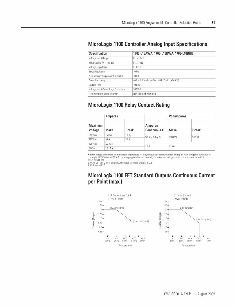
MMiiccrrooLLooggiixx 11110000 CCoonnttrroolllleerr AAnnaalloogg IInnppuutt SSppeecciiffiiccaattiioonnss
SSppeecciiffiiccaattiioonnVoltage Input Range
Input Coding (0…10V dc)
Voltage Impedance
Input Resolution
Non-linearity (in percent full scale)
Overall Accuracy
Update Time
Voltage Input Overvoltage Protection
Field Wiring to Logic Isolation
11776633--LL1166AAWWAA,, 11776633--LL1166BBWWAA,, 11776633--LL1166BBBBBB0…+10V dc
0…+1023
210 kΩ
10 bit
±0.5%
±0.5% full scale at -20…+65 °C (-4…+149 °F)
100 ms
10.5V dc
Non-isolated with logic
MMiiccrrooLLooggiixx 11110000 RReellaayy CCoonnttaacctt RRaattiinngg
MMaaxxiimmuumm VVoollttaaggee240V ac
120V ac
125V dc
24V dc
AAmmppeerreess
AAmmppeerreessCCoonnttiinnuuoouuss ‡‡
VVoollttaammppeerreess
MMaakkee BBrreeaakk MMaakkee BBrreeaakk15.0 A 1.5 A
5.0 A / 3.0 A 3600 VA 360 VA30 A 3.0 A
.22 A 1.0 A 28 VA
1.2 A
For dc voltage applications, the make/break ampere rating for relay contacts can be determined by dividing 28 VA by the applied dc voltage. Forexample, 28 VA/48V dc = 0.58 A. For dc voltage applications less than 14V, the make/break ratings for relay contacts cannot exceed 2 A.5.0 A for UL 508
3.0 A for UL 1604, Class 1, Division 2, Hazardous Locations, Group A, B, C, D‡ 3.0 A above 40° C
MMiiccrrooLLooggiixx 11110000 FFEETT SSttaannddaarrdd OOuuttppuuttss CCoonnttiinnuuoouuss CCuurrrreennttppeerr PPooiinntt ((mmaaxx..))
0.5
10°C(50°F)
30°C(86°F)
50°C(122°F)
1.5A, 70°C (158°F)
3.0A, 30°C (86°F)
70°C(158°F)
80°C(176°F)
1.0
1.5
2.0
2.5
3.0
3.5
4.0
0.25
10°C(50°F)
30°C(86°F)
50°C(122°F)
0.75A, 70°C (158°F)
Curre
nt (A
mps
)
Curre
nt (A
mps
)
FET Current per Point(1763-L16BBB)
FET Total Current(1763-L16BBB)
Temperature Temperature
1.5A, 30°C (86°F)
70°C(158°F)
80°C(176°F)
0.5
0.75
1.0
1.25
1.5
1.75
2.0

32
1763-SG001A-EN-P — August 2005
MicroLogix 1100 Programmable Controller Selection Guide
MMiiccrrooLLooggiixx 11110000 MMeemmoorryy MMoodduullee
The controller is shipped with a memory module port cover in place. You can order thememory module to provide removable backup of your User Program and User Data, or totransport your program between controllers.
MMeemmoorryy MMoodduullee ((11776633--MMMM11))
Memory modules allow:
user programs and data to be stored as backup
transport programs for use with other controllers
special safety/security features for press control and other critical applications
auto-recovery, through a power cycle, after a controller fault
comparison of programs
data file and memory module write protection
removal/insertion under power

33
1763-SG001A-EN-P — August 2005
MicroLogix 1100 Programmable Controller Selection Guide
SelectMicroLogix 1100Expansion I/OStep 6 - Select:
I/O modules - digital, analog andtemperature
record your selections in the SelectionRecord (starts on page 39)
MicroLogix 1100 controllers expand using the same 1762 I/O platform as MicroLogix 1200controllers. The 1762 I/O expansion modules provide superior functionality in a small sizedlow-cost package. A variety of modules complement and extend the capabilities ofMicroLogix 1100 controllers by maximizing the flexibility of I/O count and type.
The MicroLogix 1100 system design allows modules to be either DIN-rail or panelmounted. The DIN latches and screw mounting holes are an integral part of the package design.
Controller I/O can be expanded using up to four 1762 I/O modules.
AAddvvaannttaaggeess
Rackless design, eliminating added system costs and inventory
Small footprint with high density I/O, minimizing panel space requirements
Integral high-performance I/O bus
Software keying to prevent incorrect positioning within the system
Feature-rich I/O functionality addresses a wide range of applications
AC/DC relay, 24V dc, 120V ac and 240V ac voltages
Thermocouple/mV and RTD/Resistance temperature input modules

34
1763-SG001A-EN-P — August 2005
MicroLogix 1100 Programmable Controller Selection Guide
11776622 EExxppaannssiioonn II//OO MMoodduulleess
CCaatt.. NNoo..
1762-IA8
1762-IQ8
1762-IQ16
1762-OA8
1762-OB8
1762-OB16
1762-OW8
1762-OW16
1762-OX6I
1762-IF4
1762-OF4
1762-IF2OF2
1762-IR4
1762-IT4
DDeessccrriippttiioonnDigital:
8-Point 120V ac Input Module
8-Point Sink/Source 24V dc Input Module
16-Point Sink/Source 24V dc Input Module
8-Point 120/240V ac Triac Output Module
8-Point Sourcing 24V dc Output Module
16-Point Sourcing 24V dc Output Module
8-Point AC/DC Relay Output Module
16-Point AC/DC Relay Output Module
6-Point Isolated AC/DC Relay Output Module
Analog:
4-Channel Voltage/Current Analog Input Module
4-Channel Voltage/Current Analog Output Module
Combination 2-Channel Input 2-Channel Output Voltage/Current Analog Module
Specialty:
4-Channel RTD/Resistance Input Module
4-Channel Thermocouple/mV Input Module
11776622 DDiiggiittaall II//OO
11776622 DDiiggiittaall EExxppaannssiioonn IInnppuutt MMoodduulleess SSppeecciiffiiccaattiioonnss
SSppeecciiffiiccaattiioonn 11776622--IIAA88 11776622--IIQQ88 11776622--IIQQ1166Voltage Category 100/120V ac 24V dc (sink/source) 24V dc (sink/source)
Operating Voltage Range 79…132V ac @ 47…63 Hz 10…26.4V dc @ 55 °C (131 °F)10…30V dc @ 30 °C (86 °F)
10…26.4V dc @ 55 °C (131 °F)10…30V dc @ 30 °C (86 °F)
Number of Inputs 8 8 16
Number of Commons 1 1 2
Bus Current Draw (max.) 50 mA @ 5V dc (0.25 W) 50 mA @ 5V dc (0.25 W) 60 mA @ 5V dc (0.25 W)
Heat Dissipation (max.) 2.0 Total Watts 3.7 Total Watts 5.3 Total Watts @ 30V4.2 Total Watts @ 26.4V
Signal Delay (max.) On Delay: 20.0 msOff Delay: 20.0 ms
On Delay: 8.0 msOff Delay: 8.0 ms
On Delay: 8.0 msOff Delay: 8.0 ms
Off-State Voltage (max.) 20V ac 5V dc 5V dc
Off-State Leakage Current (max.) 2.5 mA 1.5 mA 1.5 mA
On-State Voltage (min.) 79V ac (min.) 132V ac (max.) 10V dc 10V dc
On-State Current:
minimumnominalmaximum
5.0 mA @ 79V ac @ 47 Hz12.0 mA @ 120V ac @ 60 Hz16.0 mA @ 132V ac @ 63 Hz
2.0 mA @ 10V dc8.0 mA @ 24V dc12.0 mA @ 30V dc
2.0 mA @ 10V dc8.0 mA @ 24V dc12.0 mA @ 30V dc
Inrush Current (max.) 250 mA — —
Nominal Impedance 12 kΩ @ 50 Hz10 kΩ @ 60 Hz 3 kΩ 3 kΩ
Isolated Groups Group 1: inputs 0…7(internally connected commons)
Group 1: inputs 0…7(internally connected commons)
Group 1: inputs 0…7Group 2: inputs 8…15
Input Group to Backplane Isolation
Verified by one of the following dielectric tests:1517V ac for 1 s or 2145V dc for 1 s132V ac working voltage (IEC Class 2 reinforcedinsulation)
Verified by one of the following dielectric tests: 1200V ac for 1 s or 1697V dc for 1 s75V dc working voltage (IEC Class 2 reinforced insulation)
Sinking/Sourcing Inputs - Sourcing/sinking describes the current flow between the I/O module and the field device. Sourcing I/O circuits supply (source) current to sinking field devices. Sinking I/O circuits are driven by a currentsourcing field device. Field devices connected to the negative side (DC Common) of the field power supply are sinking field devices. Field devices connected to the positive side (+V) of the field supply are sourcing field devices.
AAvvaaiillaabbllee MMoodduulleess

35
1763-SG001A-EN-P — August 2005
MicroLogix 1100 Programmable Controller Selection Guide
11776622 DDiiggiittaall EExxppaannssiioonn OOuuttppuutt MMoodduulleess SSppeecciiffiiccaattiioonnss
SSppeecciiffiiccaattiioonnVoltage Category
Operating VoltageRange
Number of Outputs
Number of Commons
Bus Current Draw(max.)
Heat Dissipation (max.)
Signal Delay (max.) -resistive load
Off-State LeakageCurrent (max.)
On-State Current (min.)
On-State Voltage Drop (min.)
Continuous Current perPoint (max.)
Continuous Current perCommon (max.)
Continuous Current perModule (max.)
Surge Current (max.)
11776622--OOAA88 11776622--OOBB88 11776622--OOBB1166 11776622--OOWW88 11776622--OOWW1166 11776622--OOXX66II100/120V ac 24V dc 24V dc AC/DC normally open relay AC/DC normally open relay AC/DC Type C Relay
85…265V ac @ 47…63 Hz 20…26.4V dc 20…26.4V dc 5…265V ac5…125V dc
5…265V ac5…125V dc
5…265V ac5…125V dc
8 8 16 8 16 6 (N.C., N.O.)
2 1 1 2 2 6
115 mA @ 5V dc (0.575 W) 115 mA @ 5V dc (0.575 W) 175 mA @ 5V dc (0.88 W) 80 mA @ 5V dc (0.40 W)90 mA @ 24V dc (2.16 W)
120 mA @ 5V dc (0.60 W)140 mA @ 24V dc (3.36 W)
110 mA @ 5V dc (0.55 W)110 mA @ 24V dc (2.64 W)
2.9 Total Watts 1.61 Total Watts
2.9 Total Watts @ 30 °C(86 °F)2.1 Total Watts @ 55 °C(131 °F)
2.9 Total Watts 5.6 Total Watts 2.8 Total Watts
On Delay: 1/2 cycleOff Delay: 1/2 cycle
On Delay: 0.1 msOff Delay: 1.0 ms
On Delay: 0.1 msOff Delay: 1.0 ms
On Delay: 10 msOff Delay: 10 ms
On Delay: 10 msOff Delay: 10 ms
On Delay: 10 msOff Delay: 20 ms
2 mA @ 132V2.5 mA at 265V 1.0 mA 1.0 mA 0 mA 0 mA 0 mA
10 mA 1.0 mA 1.0 mA 10 mA @ 5V dc 10 mA 100 mA
1.5V @ 0.5A 1.0V dc 1.0V dc — — —
0.25 A @ 55 °C (131 °F)0.5 A @ 30 °C (86 °F)
0.5 A @ 55 °C (131 °F)1.0 A @ 30 °C (86 °F)
0.5 A @ 55 °C (131 °F)1.0 A @ 30 °C (86 °F)
2.5 A (Also see 1761-SG001 (MicroLogix ProgrammableControllers Family Selection Guide), MicroLogix 1200Relay Contact Rating on Page 31.)
7 A (Also see 1761-SG001(MicroLogix ProgrammableControllers FamilySelection Guide),MicroLogix 1200 RelayContact Rating on Page 31.)
1.0 A @ 55 °C (131 °F)2.0 A @ 30 °C (86 °F)
4.0 A @ 55 °C (131 °F)8.0 A @ 30 °C (86 °F)
4.0 A @ 55 °C (131 °F)8.0 A @ 30 °C (86 °F) 8 A 8 A
7 A (Also see 1761-SG001(MicroLogix ProgrammableControllers FamilySelection Guide),MicroLogix 1200 RelayContact Rating on Page 31.)
2.0 A @ 55 °C (131 °F)4.0 A @ 30 °C (86 °F)
4.0 A @ 55 °C (131 °F)8.0 A @ 30 °C (86 °F)
4.0 A @ 55 °C (131 °F)8.0 A @ 30 °C (86 °F) 16 A 16 A 30 A
5.0 A 2.0 A 2.0 A See 1761-SG001 (MicroLogix Programmable Controllers Family Selection Guide),MicroLogix 1200 Relay Contact Rating on Page 31.
Repeatability is once every 2 seconds for a duration of 25 ms.Repeatability is once every 2 seconds @ 55 °C (131 °F), once every second @ 30 °C (86 °F) for a duration of 10 ms.

36
1763-SG001A-EN-P — August 2005
MicroLogix 1100 Programmable Controller Selection Guide
11776622 AAnnaalloogg MMoodduulleess
11776622 AAnnaalloogg EExxppaannssiioonn MMoodduulleess CCoommmmoonn SSppeecciiffiiccaattiioonnss
SSppeecciiffiiccaattiioonnBus Current Draw(max.)
Analog NormalOperating Ranges
Full Scale AnalogRanges
Resolution
Repeatability
Input and OutputGroup to SystemIsolation
11776622--IIFF44 11776622--IIFF22OOFF22 11776622--OOFF4440 mA @ 5V dc50 mA @ 24V dc
40 mA @ 5V dc105 mA @ 24V dc
40 mA @ 5V dc165 mA @ 24V dc
Voltage: -10…+10V dcCurrent: 4…20 mA
Voltage: 0…10V dcCurrent: 4…20 mA
Voltage: 0…10V dcCurrent: 4…20 mA
Voltage: -10.5…+10.5V dcCurrent: -21…+21 mA
Voltage: 0…10.5V dcCurrent: 0…21 mA
Voltage: 0…10.5V dcCurrent: 0…21 mA
15 bits 12 bits (unipolar) 12 bits (unipolar)
±0.1% ±0.1% ±0.1%
30V ac/30V dc rated working voltage ‡(N.E.C. Class 2 required)(IEC Class 2 reinforced insulation) type test: 500V ac or 707V dc for 1 minute
30V ac/30V dc rated working voltage(IEC Class 2 reinforced insulation) type test: 500V ac or 707V dc for 1minute
The over- or under-range flag is set when the normal operating range is exceeded. The module continues to convert the analog input up to the maximum full scale range.Repeatability is the ability of the input module to register the same reading in successive measurements for the same input signal.
‡ Rated working voltage is the maximum continuous voltage that can be applied at the terminals with respect to earth ground.
11776622 AAnnaalloogg EExxppaannssiioonn IInnppuutt MMoodduulleess SSppeecciiffiiccaattiioonnss
SSppeecciiffiiccaattiioonn 11776622--IIFF44 11776622--IIFF22OOFF22Number of Inputs 4 differential (bipolar) 2 differential (unipolar)
Update Time (typical) 130, 250, 290, 450, 530 ms (selectable) 2.5 ms
A/D Converter Type Successive approximation Successive approximation
Common Mode Voltage Range § ±27V ±27V
Common Mode Rejection ♣ > 55 dB @ 50 and 60 Hz > 55 dB @ 50 and 60 Hz
Non-linearity (in percent full scale) ±0.1% ±0.1%
Typical Overall Accuracy ±0.3% full scale at 0…55 °C (32…131 °F)±0.24% full scale at 25 °C (77 °F)
±0.5% full scale at 0…55 °C (32…131 °F)±0.3% full scale at 25 °C (77 °F)
Input Impedance Voltage Terminal: 200 kΩCurrent Terminal: 275 Ω
Voltage Terminal: 200 kΩCurrent Terminal: 250 Ω
Current Input Protection ±32 mA ±32 mA
Voltage Input Protection ±30V ±30V
Channel Diagnostics Over or under range or open circuit condition by bit reporting for analog inputs.
§ For proper operation, both the plus and minus input terminals must be within ±27V of analog common.♣ Vcm = 1 V pk-pk AC
Vcm = 0 (includes offset, gain, non-linearity and repeatability error terms)

37
1763-SG001A-EN-P — August 2005
MicroLogix 1100 Programmable Controller Selection Guide
11776622 AAnnaalloogg EExxppaannssiioonn OOuuttppuutt MMoodduulleess SSppeecciiffiiccaattiioonnss
SSppeecciiffiiccaattiioonnNumber of Outputs
Update Time (typical)
D/A Converter Type
Resistive Load on Current Output
Load Range on Voltage Output
Reactive Load, Current Output
Reactive Load, Voltage Output
Typical Overall Accuracy
Output Ripple, range 0…500 Hz(referred to output range)
Non-linearity (in percent full scale)
Open and Short-Circuit Protection
Open Protection
11776622--IIFF22OOFF22 11776622--OOFF442 single-ended (unipolar) 4 single-ended (bipolar)
4.5 ms 2.5 ms
Resistor string R-2R Ladder voltage switching
0…500 Ω (includes wire resistance) 0…500 Ω (includes wire resistance)
> 1 kΩ > 1 kΩ
< 1 mH < 1 mH
< 1 µF < 1 µF
±1% full scale @ 0…55 °C (32…131 °F)±0.5% full scale @ 25 °C (77 °F)
±1% full scale @ 0…55 °C (32…131 °F)±0.5% full scale @ 25 °C (77 °F)
< ±0.1% < ±0.1%
< ±0.5% < ±0.5%
Continuous Continuous
±32 mA ±32 mA
Includes offset, gain, non-linearity and repeatability error terms.
11776622 TTeemmppeerraattuurree IInnppuutt MMoodduulleess
Use these modules as a cost-effective means of addressing process applications thatrequire temperature measurement and control. Each channel can be individuallyconfigured using RSLogix 500 programming software. On-screen configuration allows youto choose the input type, filtering frequency, data format and status data. On-boardscaling is also provided.

38
1763-SG001A-EN-P — August 2005
MicroLogix 1100 Programmable Controller Selection Guide
11776622 TTeemmppeerraattuurree EExxppaannssiioonn IInnppuutt MMoodduulleess SSppeecciiffiiccaattiioonnss
SSppeecciiffiiccaattiioonn
Bus Current Draw (max.)
Number of Channels
Accepted Inputs
Filter Frequency
Temperature Units
Data Formats
Accuracy @ 25 °C (77 °F)
Accuracy @ 0…55 °C (32…131 °F)
Channel Update Time (typical)
Channel Diagnostics
Calibration
Common Mode Noise Rejection
Normal Mode Noise Rejection
Input Group to System Isolation
Channel-to-Channel Isolation
Repeatability
Input Impedance
11776622--IITT44 11776622--IIRR4440 mA @ 5V dc50 mA @ 24V dc
40 mA @ 5V dc50 mA @ 24V dc
4 input channels plus a CJC sensor 4 input channels
Thermocouples Types: J, K, T, E, R, S, B, N, CMillivolt Input Ranges: ±50 mV and ±100 mV
RTDs: Platinum (385 and 3916), Copper (426), Nickel (672 and 618), Nickel-Iron (518)Resistance Ranges: 0…3000 Ω
10 Hz…1 kHz 10 Hz…1 kHz
°C or °F °C or °F
Raw/Proportional, Engineering Units, Engineering Units x 10, Scaled-for-PID, Percent Range
Thermocouple Inputs: ±0.5…±3.0 °C (±0.9…±5.4 °F) depending onthermocouple typeMillivolt Inputs: ±15…±20 mV
With Autocalibration enabled…RTD Inputs: ±0.2…±0.6 °C (±0.36…±1.08 °F) depending on RTD typeResistance Inputs: ±0.5…±1.5 Ω depending on resistance value
±0.8…±10 °C (±1.5…±18 °F) depending on thermocouple typeMillivolt Inputs: ±25…±30 mV
With Autocalibration enabled…RTD Inputs: ±0.4…±1.1 °C (±0.72…±1.98 °F) depending on RTD typeResistance Inputs: ±0.25…±2.5 Ω depending on resistance value
7…303 ms per enabled channel + CJC update time, depending on filterselection (CJC update time is equal to the largest enabled channel's updatetime.)
6…303 ms per enabled channel, depending on filter selection
Over- or under-range and open circuit by bit reporting Over or under range and open circuit by bit reporting
The module performs autocalibration on channel enable and on a configuration change between channels. You can also program the module to calibrateevery five minutes.
115 dB minimum @ 50 Hz (with 10 Hz or 50 Hz filter)115 dB minimum @ 60 Hz (with 10 Hz or 60 Hz filter)
110 dB minimum @ 50 Hz (with 10 or 50 Hz filter)110 dB minimum @ 60 Hz (with 10 or 60 Hz filter)
85 dB minimum @ 50 Hz (with 10 Hz or 50 Hz filter)85 dB minimum @ 60 Hz (with 10 Hz or 60 Hz filter)
70 dB minimum @ 50 Hz (with 10 or 50 Hz filter)70 dB minimum @ 60 Hz (with 10 or 60 Hz filter)
720V dc for 1 minute 707V dc for 1 minute
±10V dc ±10V dc
Thermocouples @ 25 °C (77 °F) and 10 Hz filter selected: ±0.1…±2.0 °C (±0.18…±3.6 °F) depending on thermocouple typeMillivolt Inputs: ±6 µV
±0.1 °C (±0.18 °F) for Nickel and Nickel-Iron±0.2 °C (±0.36 °F) for other RTD inputs±0.04 Ω for 150 Ω resistances±0.2 Ω for other resistances
> 10 MΩ > 10 MΩ
Repeatability is the ability of the input module to register the same reading in successive measurements for the same input signal.

39
1763-SG001A-EN-P — August 2005
MicroLogix 1100 Programmable Controller Selection Guide
Fill in YourSelection Listing
Step 7 - Select:
CCaatt.. NNoo.. DDeessccrriippttiioonn QQuuaannttiittyy SSeelleecctteeddMMiiccrrooLLooggiixx 11110000 CCoonnttrroolllleerrss aanndd AAcccceessssoorriieess1763-L16AWA MicroLogix 1100 16-Point AC Controller
1763-L16BWA MicroLogix 1100 16-Point AC Controller
1763-L16BBB MicroLogix 1100 16-Point DC Controller
MMiiccrrooLLooggiixx 11110000 II//OO1762-IA8 8-Point 120V ac Input Module
1762-IF2OF2 Combination 2-Channel Input 2-Channel OutputVoltage/Current Analog Module
1762-IF4 4-Channel Voltage/Current Analog Input Module
1762-IQ16 16-Point Sink/Source 24V dc Input Module
1762-IQ8 8-Point Sink/Source 24V dc Input Module
1762-IR4 4-Channel RTD/Resistance Input Module
1762-IT4 4-Channel Thermocouple/mV Input Module
1762-OA8 8-Point 120/240V ac Triac Output Module
1762-OB16 16-Point Sourcing 24V dc Output Module
1762-OB8 8-Point Sourcing 24V dc Output Module
1762-OF4 4-Channel Voltage/Current Analog Output Module
1762-OW16 16-Point AC/DC Relay Output Module
1762-OW8 8-Point AC/DC Relay Output Module
1762-OX6I 6-Point Isolated AC/DC Relay Output Module
MMiiccrrooLLooggiixx CCoommmmuunniiccaattiioonn aanndd IInntteerrffaaccee DDeevviicceess1761-NET-AIC MicroLogix Advanced Interface Converter Module
1761-NET-DNI MicroLogix DeviceNet Interface Module
1761-NET-ENI MicroLogix EtherNet/IP Interface Module
1761-NET-ENIW MicroLogix EtherNet/IP Interface Module with Web ServerFunctionality
PPrrooggrraammmmiinngg SSooffttwwaarree9324-RL0100ENE RSLogix 500 Starter
9324-RL0300ENE RSLogix 500 Programming for the SLC 500 and MicroLogixFamilies
9324-RL0700NXENE RSLogix 500 Professional
CCaabblleess
1747-UIC Universal Serial Bus (USB) to DH-485 Interface Converter
9300-USBS Universal Serial Bus to DF1 Interface Converter
1761-CBL-AC00 RS-232 Operating Cable, 9-Pin D Shell to 9-Pin D Shell(MicroLogix), 0.5 m (1.5 ft)
1761-CBL-AM00 RS-232 Operating Cable, 8-Pin Mini DIN to 8-Pin Mini DIN(MicroLogix), 0.5 m (1.5 ft)
1761-CBL-AP00 (Series C or later for Class I Div 2 applications) RS-232 Operating Cable, 8-Pin Mini DIN to 9-Pin D Shell(MicroLogix), 45 CM (17.7 in)
1761-CBL-HM02 (Series C or later for Class I Div 2 applications) RS-232 Operating/Programming Cable, 8-Pin Mini DIN to 8-Pin Mini DIN (MicroLogix), 2 M (6.5 ft)
1761-CBL-PM02 (Series C or later for Class I Div 2 applications) RS-232 Operating/Programming Cable, 8-Pin Mini DIN to 9-Pin D Shell (MicroLogix), 2 M (6.5 ft)
2707-NC9 (Series C or later for Class I Div 2 applications) RS-232 Operating/Programming Cable, 8-Pin Mini DIN to 8-Pin Mini DIN, 15 M (49.2 ft)
1763-NC01 DH-485, 8-Pin Mini DIN to 6-Pin DH-485 connector(MicroLogix), 30 cm (11.8 in)
SSeelleeccttiioonn RReeccoorrdd
all catalog numbers required for yoursystem specification

39
1763-SG001A-EN-P — August 2005
MicroLogix 1100 Programmable Controller Selection Guide
Fill in YourSelection Listing
Step 7 - Select:
CCaatt.. NNoo.. DDeessccrriippttiioonn QQuuaannttiittyy SSeelleecctteeddMMiiccrrooLLooggiixx 11110000 CCoonnttrroolllleerrss aanndd AAcccceessssoorriieess1763-L16AWA MicroLogix 1100 16-Point AC Controller
1763-L16BWA MicroLogix 1100 16-Point AC Controller
1763-L16BBB MicroLogix 1100 16-Point DC Controller
MMiiccrrooLLooggiixx 11110000 II//OO1762-IA8 8-Point 120V ac Input Module
1762-IF2OF2 Combination 2-Channel Input 2-Channel OutputVoltage/Current Analog Module
1762-IF4 4-Channel Voltage/Current Analog Input Module
1762-IQ16 16-Point Sink/Source 24V dc Input Module
1762-IQ8 8-Point Sink/Source 24V dc Input Module
1762-IR4 4-Channel RTD/Resistance Input Module
1762-IT4 4-Channel Thermocouple/mV Input Module
1762-OA8 8-Point 120/240V ac Triac Output Module
1762-OB16 16-Point Sourcing 24V dc Output Module
1762-OB8 8-Point Sourcing 24V dc Output Module
1762-OF4 4-Channel Voltage/Current Analog Output Module
1762-OW16 16-Point AC/DC Relay Output Module
1762-OW8 8-Point AC/DC Relay Output Module
1762-OX6I 6-Point Isolated AC/DC Relay Output Module
MMiiccrrooLLooggiixx CCoommmmuunniiccaattiioonn aanndd IInntteerrffaaccee DDeevviicceess1761-NET-AIC MicroLogix Advanced Interface Converter Module
1761-NET-DNI MicroLogix DeviceNet Interface Module
1761-NET-ENI MicroLogix EtherNet/IP Interface Module
1761-NET-ENIW MicroLogix EtherNet/IP Interface Module with Web ServerFunctionality
PPrrooggrraammmmiinngg SSooffttwwaarree9324-RL0100ENE RSLogix 500 Starter
9324-RL0300ENE RSLogix 500 Programming for the SLC 500 and MicroLogixFamilies
9324-RL0700NXENE RSLogix 500 Professional
CCaabblleess
1747-UIC Universal Serial Bus (USB) to DH-485 Interface Converter
9300-USBS Universal Serial Bus to DF1 Interface Converter
1761-CBL-AC00 RS-232 Operating Cable, 9-Pin D Shell to 9-Pin D Shell(MicroLogix), 0.5 m (1.5 ft)
1761-CBL-AM00 RS-232 Operating Cable, 8-Pin Mini DIN to 8-Pin Mini DIN(MicroLogix), 0.5 m (1.5 ft)
1761-CBL-AP00 (Series C or later for Class I Div 2 applications) RS-232 Operating Cable, 8-Pin Mini DIN to 9-Pin D Shell(MicroLogix), 45 CM (17.7 in)
1761-CBL-HM02 (Series C or later for Class I Div 2 applications) RS-232 Operating/Programming Cable, 8-Pin Mini DIN to 8-Pin Mini DIN (MicroLogix), 2 M (6.5 ft)
1761-CBL-PM02 (Series C or later for Class I Div 2 applications) RS-232 Operating/Programming Cable, 8-Pin Mini DIN to 9-Pin D Shell (MicroLogix), 2 M (6.5 ft)
2707-NC9 (Series C or later for Class I Div 2 applications RS-232 Operating/Programming Cable, 8-Pin Mini DIN to 8-Pin Mini DIN, 15 M (49.2 ft)
1763-NC01 DH-485, 8-Pin Mini DIN to 6-Pin DH-485 connector(MicroLogix), 30 cm (11.8 in)
SSeelleeccttiioonn RReeccoorrdd
all catalog numbers required for yoursystem specification

Publication 1763-SG001A-EN-P ⎯ August 2005 Copyright © 2005 Rockwell Automation, Inc. All rights reserved. Printed in USA.
RRoocckkwweellll AAuuttoommaattiioonn SSuuppppoorrttRockwell Automation provides technical information on the web to assist you in using our products. Athttp://support.rockwellautomation.com, you can find technical manuals, a knowledge base of FAQs, technical and application notes,sample code and links to software service packs, and a MySupport feature that you can customize to make the best use of these tools.
For an additional level of technical phone support for installation, configuration and troubleshooting, we offer TechConnect Supportprograms. For more information, contact your local distributor or Rockwell Automation representative, or visithttp://support.rockwellautomation.com.
IInnssttaallllaattiioonn AAssssiissttaanncceeIf you experience a problem with a hardware module within the first 24 hours of installation, please review the information that iscontained in this manual. You can also contact a special Customer Support number for initial help in getting your module up and running.
United States
Outside United States
1.440.646.3223Monday - Friday, 8am - 5 pm EST
Please contact your local Rockwell Automation representative for any technical support issues.
NNeeww PPrroodduucctt SSaattiissffaaccttiioonn RReettuurrnnWe test all of our products to ensure that they are fully operational when shipped from the manufacturing facility. However, if yourproduct is not functioning and needs to be returned:
United States
Outside United States
Contact your distributor. You must provide a Customer Support case number (see phone number above to obtain one) to your distributor in order to complete thereturn process.
Please contact your local Rockwell Automation representative for return procedure.
MicroLogix, SLC and RSLogix are trademarks of Rockwell Automation, Inc. Modbus is a trademark of Modicon.