Embed Size (px)
Citation preview
BRIMACOMBE, J.K., KUMAR, S.. HLADY. CO., and SAMARASEKERA. I.V. The continuous casting of stainless steels. INFACON 6.Proceedings olllle 1st 1"lenwtiofllll Chromium Steel and Alloys Congress, Cape TOIVII. Volume 2. Johannesburg, SAIMM, 1992. pp. 7-23.
The Continuous Casting of Stainless Steels
J.K. BRIMACOMBE, S. KUMAR, C.O. HLADY, and LV. SAMARASEKERA
Centre jar Metallurgical Process Engineering, University ofBritish Columbia, Canada
The continuous casting of stainless steels is now an established technology, althoughnewer processes like thin-strip casting and horizontal casting are the harbingers of anemerging era. This review examines the various aspects of the continuous casting ofstainless steels. The different processes employed to manufacture stainless-steel billets,blooms, slabs, and strip are described. Fundamental knowledge pertaining to thecasting of stainless steels is examined to provide a basic understanding of the importantevents that occur during the process. Quality problems in the cast products arediscussed in terms of the mechanisms and operating design parameters that influencethem.
IntroductionStainless steel has been continuously cast for more thanfour decades I,The first major installation in North Americafor the continuous casting of stainless-steel slabs wasestablished in the early 1950's at Atlas Steel in Canada'.Over the years, the continuous-casting process for theproduction of steel billets, blooms, and slabs has emergedas one of the most important technologies in the steelindustry worldwide2, particularly in the stainless-steelsector. A revolutionary development in refining in the1970's, namely the invention of the AOO, followed by thedevelopment of similar novel processes such as the VOD,paved the way for the production of high-quality stainlesssteel at reduced cost. Stainless steel is now manufacturedby the process route shown in Figure 1, where, followingmelting in an electric furnace, the molten steel is refined inan AOO or VOO furnace and then stirred to homogenizethe temperature before continuous casting3- 7.
STEELMAKING( Elltctrlc Arc """-I
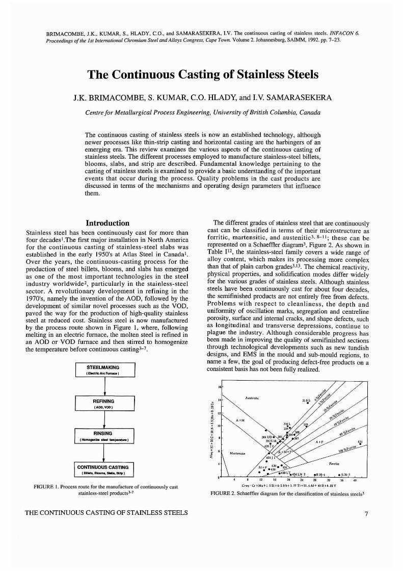
The different grades of stainless steel that are continuouslycast can be classified in terms of their microstructure asferritic, martensitic, and austenitic3, 8-1 I; these can berepresented on a Schaeffler diagramJ , Figure 2. As shown inTable 112, the stainless-steel family covers a wide range ofalloy content, which makes its processing more complexthan that of plain carbon gradesJ,IJ. The chemical reactivity,physical properties, and solidification modes differ widelyfor the various grades of stainless steels. Although stainlesssteels have been continuously cast for about four decades,the semifinished products are not entirely free from defects.Problems with respect to cleanliness, the depth andunifonnity of oscillation marks, segregation and centrelineporosity, surface and internal cracks, and shape defects, suchas longitudinal and transverse depressions, continue toplague the industry, Although considerable progress hasbeen made in improving the quality of semifil1ished sectionsthrough technological developments such as new tundishdesigns, and EMS in the mould and sub-mould regions, toname a few, the goal of producing defect-free products on aconsistent basis has not been fully realized.
"+ "~"f 10Z•+u ,
~i•!
A+M
MIIII .....;t"
" "
A' F ',I,Ql.l<y,.~c.i\\e
F""it"
FIGURE I. Process route for the manufacture of continuously caststainless-steel products)'7
THE CONTINUOUS CASTING OF STAINLESS STEELS
C'C<J-Cc I·Ma+I.SSi "0.SNb11.nTi·UI.1 Alt 101l ..M.UV
FIGURE 2. SchaefOer diagram for the classification of stainless steels)
7
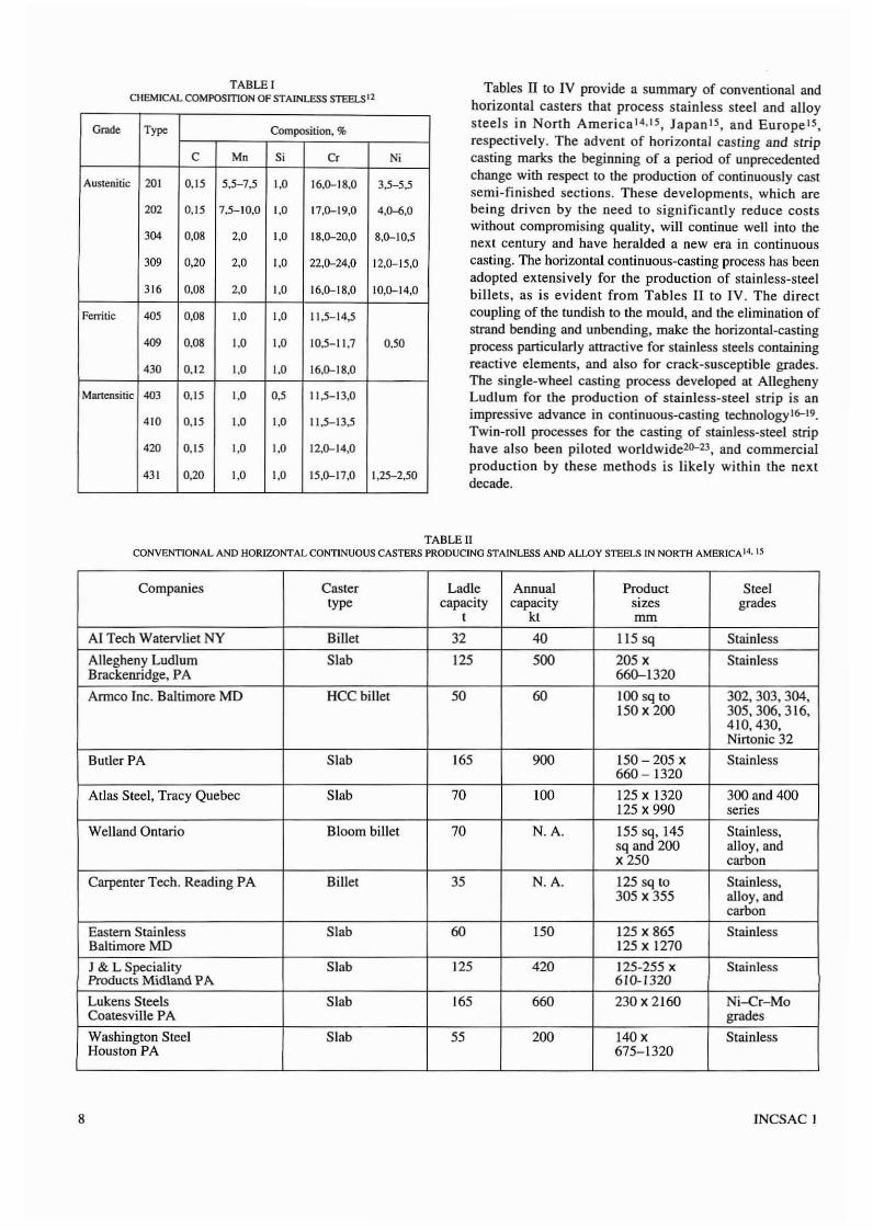
TABLE ICHEMICAL COMPOSmON OF STAINLESS STEELS 12
Grade Type Composition. %
C Mn 51 Cr N1
AusteniLic 201 0,15 5,5-7,5 1,0 16,~18,0 3,5-5,5
202 0,15 7,5-10,0 1,0 17,~19,0 4,~,0
304 0,08 2,0 1,0 18,~20,0 8,~10,5
309 0,20 2,0 1,0 22,~24,0 12,~15,0
316 0,08 2,0 1,0 16,~18,0 10,~14,0
Fcrritic 405 0,08 1,0 1,0 11,5-14,5
409 0,08 1,0 \,0 10,5-11,7 0,50
430 0,12 1,0 1,0 16,~18,0
Mancnsitic 403 0,15 1,0 0,5 11,5-13,0
410 0,15 1,0 1,0 11,5-13,5
420 0,15 1,0 1,0 12,~14,0
431 0,20 1,0 1,0 15,~17,0 1,25-2,50
Tables II to IV provide a summary of conventional andhorizontal casters that process stainless steel and alloysteels in North America l4 . 15 , Japan 15 • and Europe15,respectively. The advent of horizontal cas ring and stripcasting marks the beginning of a period of unprecedentedchange with respect to the production of continuously castsemi-finished sections. These developments, which arebeing driven by the need to significantly reduce costswithout compromising quality. will continue well into thenext century and have heralded a new era in continuouscasting. The horizontal continuous-casting process has beenadopted extensively for the production of stainless-steelbillets, as is evident from Tables II to IV. The directcoupling of the tundish to the mould, and the elimination ofstrand bending and unbending, make the horizontal-castingprocess particularly attractive for stainless steels containingreactjve elements, and also for crack-susceptible grades.The single-wheel casting process developed at AlleghenyLudlum for the production of stainless-steel strip is animpressive advance in continuous-casting technologyl6-19.Twin-roll processes for the casting of stainless-steel striphave also been piloted worldwide2o-23 , and commercialproduction by these methods is likely within the nextdecade.
TABLE IICONVENTIONAL AND HORlZONTALCONTlNUOUS CASTERS PRODUCING STAINLESS AND ALLOY STEELS IN NORTH AMERICAI4, 15
Companies Caster Ladle Annual Product Steeltype capacity capacity sizes grades
t let mm
AI Tech Watervliet NY Billet 32 40 115 sq Stainless
Allegheny Ludlum Slab 125 500 205 X StainlessBrackenridge, PA 660-1320
Armco Inc. Baltimore MD HCC billet 50 60 100 sq to 302, 303, 304,150 X200 305, 306, 316,
410,430,Nirtonic 32
Butler PA Slab 165 900 150-205 x Stainless660 - 1320
Atlas Steel, Tracy Quebec Slab 70 100 125 x 1320 300 and 400125 x 990 series
Weiland Ontario Bloom billet 70 N.A. 155 sq, 145 Stainless,sq and 200 alloy, andX250 carbon
Carpenter Tech. Reading PA Billet 35 N.A, 125 sq to Stainless,305 x 355 alloy, and
carbon
Eastern Stainless Slab 60 150 125 x 865 StainlessBaltimore MD 125 X 1270
J & L Speciality Slab 125 420 125-255 x StainlessProducts Midland PA 610-1320
Lukens Steels Slab 165 660 230 x 2160 Ni-Cr-MoCoatesville PA grades
Washington Steel Slab 55 200 140 x StainlessHouston PA 675-1320
8 INCSAC I
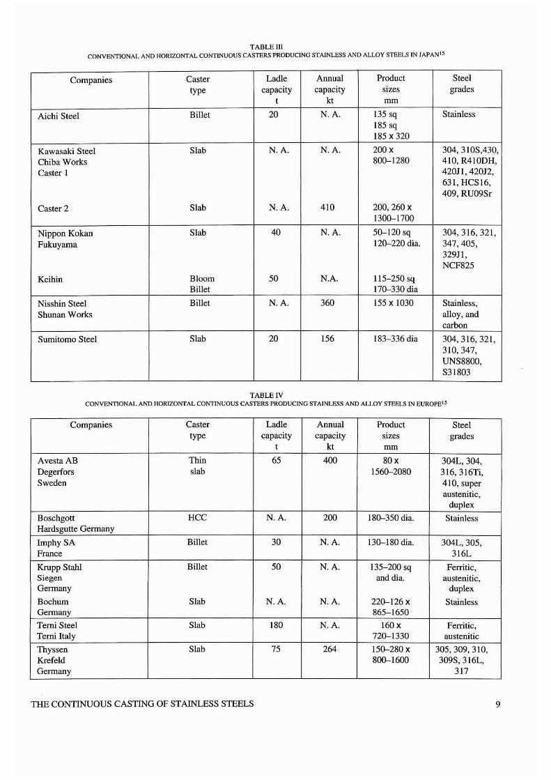
TABLE IIICONVENTIONAL AND HORIZONTAL CONTINUOUS CASTERS PRODUCING STAINLESS AND ALLOY STEELS IN JAPANIS
Companies Caster Ladle Annual Product Steeltype capacity capacity sizes grades
t kt mm
Aichi Steel Billet 20 N.A. 135 sq Stainless185 sq185 X 320
Kawasaki Steel Slab N.A. N.A. 200 X 304, 31 OS,430,Chiba Works 800-1280 410, R410DH,Caster I 420J I, 420J2,
631, HCSI6,409, RU09Sr
Caster 2 Slab N.A. 410 200,260 X
1300-1700
Nippon Kokan Slab 40 N.A. 50-120 sq 304,316,321,Fukuyama 120-220 rna. 347,405,
329Jl,NCF825
Keihin Bloom 50 N.A. 115-250 sqBillet 170-330 dia
Nisshin Steel Billet N.A. 360 155 X 1030 StainJess,Shunan Works alloy, and
carbon
Sumitomo Steel Slab 20 156 183-336 dia 304,316,321,310,347,UNS8800,S31803
TABLE IVCONVENTIONAL AND HORIZONTAL CONTINUOUS CASTERS PRODUCING STAINLESS AND ALLOY STEELS IN EUROPEIS
Companies Caster Ladle Annual Product Steeltype capacity capacity sizes grades
t kt mrn
Avesta AB Thin 65 400 80x 304L,304,Degerfors slab 1560-2080 316,316Ti,Sweden 410, super
austenitic,duplex
Boschgott HCC N.A. 200 180-350 dia. StainlessHardsgutte Germany
ImphySA Billet 30 N.A. 130-180 dia. 304L,305,France 316L
Krupp StaW Billet 50 N.A. 135-200 sq Ferritic,Siegen anddia. austenitic,Germany duplex
Bochum Slab N.A. N.A. 220-126 X StainlessGermany 865-1650
Temi Steel Slab 180 N.A. 160x Ferritic,Terni Italy 720-1330 austenitic
Thyssen Slab 75 264 150-280 X 305,309,310,Krefeld 800-1600 309S,316L,Germany 317
THE CONTINUOUS CASTING OF STAINLESS STEELS 9
This paper reviews the state-of-the-art in the productionof stainless steels by continuous casting. with specialattention to new developments and product quality. Thesolidification structure and high-temperature mechanicalbehaviour of a variety of stainless-steel grades areexamined and linked to quality problems such assegregation and crack formation. The mechanisms involvedin the fonnation of surface and internal cracks, as weU as inlongitudinal and transverse depressions, are also described;and the influence of machine design and operatingparameters on these defects is delineated.
Continuous Casting Processes for StainlessSteels
Conventional Continuous Casting
The conventional continuous-casting process for billets,blooms, and slabs has been the subject of detailed analysesfor the past three decades. The knowledge generated isbased on the results of mathematical modelling, physicalmodelling, in-plant measurements, and laboratoryexperiments, and provides important linkages amongquality problems and process (operating and design)parameters2. Details concerning optimization of the processparameters from the viewpoint of quality products are welldocumented in the literature 24- 27 . Numerous newtechnologies are being evaluated in tbis area to furtherenhance the quality of continuously cast products.
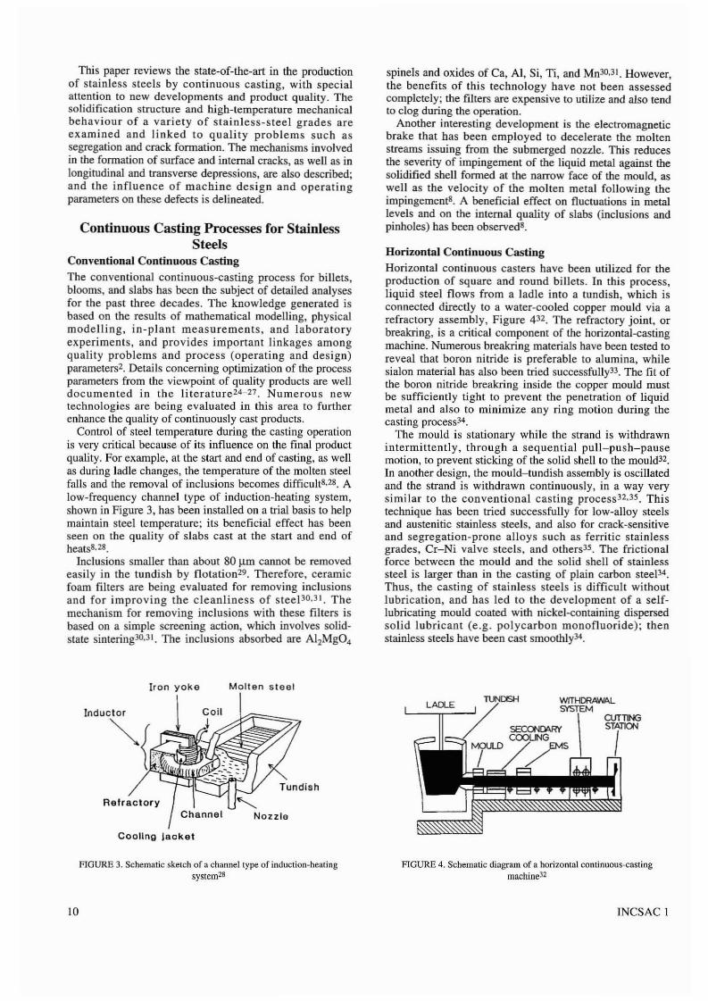
Control of steel temperature during the casting operationis very critical because of its influence on the final productquality. For example, at the start and end of casting, as wellas during ladle changes, the temperature of the molten steelfalls and the removal of inclusioos becomes difficult',2'. Alow-frequency channel type of induction-heating system,shown in Figure 3, has been installed on a trial basis to helpmaintain steel temperature~ its beneficial effect has beenseen on the quality of slabs cast at the start and end ofheats'·2'.
Inclusions smaller than about 80 J.lrn cannot be removedeasily in the tundish by flotation29. Therefore, ceramicfoam filters are being evaluated for removing i.Delusionsand for improving the cleanliness of steePO.31. Themechanism for removing inclusions with these filters isbased on a simple screening action, which involves solidstate sintering30,Jl. The inclusions absorbed are AI2MgO.
Molten steel
Inductor
Tundish
RefractoryNozzle
Cooling Jacket
HGVRE 3. Schematic sketch of a channellype of induction-heatingsystem28
10
spinels and oxides of Ca, AI, Si, Ti, and MnJO,Jl. However,the benefits of this technology have not been assessedcompletely~ the filters are expensive to utilize and also tendto clog during the operation.
Another interesting development is the electromagneticbrake that has been employed to decelerate the moltenstreams issuing from the submerged nozzle. This reducesthe severity of impingement of the liquid metal against thesolidified shell formed at the narrow face of the mould, aswell as the velocity of the molten metal following theimpingements. A beneficial effect on fluctuations in metallevels and on the internal quality of slabs (inclusions andpinholes) has been observed'.
Horizontal Continuous Casting
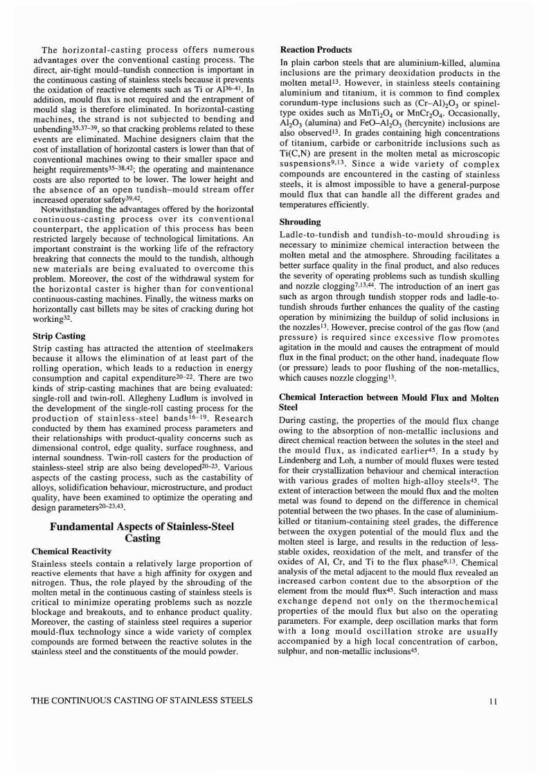
Horizontal continuous casters have been utilized for theproduction of square and round billets. In this process,liquid steel flows from a ladle into a tundish, which isconnected directly to a water-cooled copper mould via arefractory assembly, Figure 432. The refractory joint, orbreakring, is a critical component of the horiwntal-castingmachine. Numerous breakring materials have been tested toreveal that boron nitride is preferable to alumina, whilesialon material has also been tried successfully33. The fit ofthe boron nitride breakring inside the copper mould mustbe sufficiently tight to prevent the penetration of liquidmetal and also to minimize any ring motion during thecasting process34.
The mould is stationary while the strand is withdrawnintermittently, through a sequential pull-push-pausemotion, to prevent sticking of the solid shell to the mould".In another design, the mould-tundish assembly is oscillatedand the strand is withdrawn continuously, in a way verysimilar to the conventional casting process 32•35 . Thistechnique has been tried successfuUy for low-alloy steelsand austenitic stainless steels, and also for crack-sensitiveand segregation-prone alloys such as ferritic stainlessgrades, Cr-Ni valve steels, and others35. The frictionalforce between the mould and the solid shell of stainlesssteel is larger than in the casting of plain carbon steeP4.Thus, tbe casting of stainless steels is difficult withoutlubrication, and has led to the development of a selflubricating mould coated with nickel-containing dispersedsolid lubricant (e.g. polycarbon monofluoride); thenstainless steels have been cast smoothly34.
FIGURE 4. Schematic diagram of a horizontal cOnljnuous~cas(ingmachine32
INCSAC I
The horizontal-casting process offers numerousadvantages over the conventional casting process. Thedirect, air-tight mould-tundish connection is important inthe continuous casting of stainless steels because it preventsthe oxidation of reactive elements such as Ti or AJ36-41. Inaddition. mould flux is not required and the entrapment ofmould slag is therefore eliminated. In horizontal-castingmachines, the strand is not subjected to bending andunbending35•J1- 39, so that cracking problems related to theseevents are eliminated. Machine designers claim that thecost of installation of horizontal casters is lower than that ofconventional machines owing to their smaller space andheight requirements35-38,42; the operating and maintenancecosts are also reported to be lower. The lower height andthe absence of an open tundisb-mould stream offerincreased operator safety39A2.
Notwithstanding the advantages offered by the horizontalcontinuous-casting process over its conventionalcounterpart. the application of this process has beenrestricted largely because of technological limitations. Animportant constraint is the working life of the refractorybreakring that connects the mould to the tundish, althoughnew materials are being evaluated to overcome thisproblem. Moreover, the cost of the withdrawal system forthe horizontal caster is higher than for conventionalcontinuous-casting machines. Finally, the witness marks onhorizontally cast billets may be sites of cracking during hotworking32.
Strip CastingStrip casting has attracted the attention of steel makersbecause it allows the elimination of at least part of therolling operation, which leads to a reduction in energyconsumption and capital expenditure20-22. There are twokinds of strip-casting machines that are being evaluated:single-roll and twin-roll. Allegheny Ludlum is involved inthe development of the single-roll casting process for theproduction of stainless-steel bands I6- 19 . Researchconducted by them has examined process parameters andtheir relationships with product-quality concerns such asdimensional control. edge quality, surface roughness, andinternal soundness. Twin-roll casters for the production ofstainless-steel strip are also being developed20-23 . Variousaspects of the casting process, such as the castability ofalloys, solidification behaviour, microstructure, and productquality. have been examined to optimize the operating anddesign parameters20-23,4J.
Fundamental Aspects of Stainless-SteelCasting
Chemical Reactivity
Stainless steels contain a relatively large proportion ofreactive elements that have a high affinity for oxygen andnitrogen. Thus, the role played by the shrouding of themolten metal in the continuous casting of stainless steels iscritical to minimize operating problems such as nozzleblockage and breakouts, and to enhance product quality.Moreover, the casting of stainless steel requires a superiormould-flux technology since a wide variety of complexcompounds are formed between the reactive solutes in thestainless steel and the constituents of the mould powder.
THE CONTINUOUS CASTING OF STAINLESS STEELS
Reaction Products
In plain carbon steels that are aluminium-killed, aluminainclusions are the primary deoxidation products in themolten metal lJ. However, in stainless steels containingaluminium and titanium, it is common to find complexcorundum-type inclusions such as (Cr-A1hOJ or spineltype oxides such as MnTi20 4 or MnCr204' Occasionally.A1,O, (alumina) and FeO-Al,O, (hercynite) inclusions arealso observed 13. In grades containing high concentrationsof titanium, carbide or carbonitride inclusions such asTi(C,N) are present in the molten metal as microscopicsuspensions9. 13 . Since a wide variety of complexcompounds are encountered in the casting of stainlesssteels. it is almost impossible to have a general-purposemould flux that can bandle all the different grades andtemperatures efficiently.
Shrouding
Ladle-to-lundish and tundish-to-rnould shrouding isnecessary to minimize chemical interaction between themolten metal and the atmosphere. Shrouding facilitates abelter surface quality in the final product, and also reducesthe severity of operating problems such as tundish skullingand nozzle c1ogging7.13,44 The introduction of an inert gassuch as argon through tundish stopper rods and ladle-totundish shrouds further enhances the quality of the castingoperation by minimizing the buildup of solid inclusions inthe nozzles l3. However, precise control of the gas flow (andpressure) is required since excessive flow promotesagitation in the mould and causes the entrapment of mouldflux in the final product; on the other hand, inadequate flow(or pressure) leads to poor flushing of the non-metallics,which causes nozzle clogging l3 .
Chemical Interaction between Mould Flux and MoltenSteel
During casting, the properties of the mould flux changeowing to the absorption of non-metallic inclusions anddirect chemical reaction between the solutes in the steel andthe mould flux, as indicated earlier45. In a study byLindenberg and Loh, a number of mould fluxes were testedfor their crystallization behaviour and chemical interactionwith various grades of molten high-alloy steels". Theextent of interaction between the mould flux and the moltenmetal was found to depend on the difference in chemicalpotential between the two phases. In the case of aluminiumkilled or titanium-containing steel grades. the differencebetween the oxygen potential of the mould flux and themolten steel is large, and results in the reduction of less·stable oxides, reoxidation of the meh, and transfer of theoxides of AI, Cr, and Ti to the flux phase.· l3 . Chemicalanalysis of the metal adjacent to the mould flux revealed anincreased carbon content due to the absorption of lhcelement from the mould flux45. Such interaction and massexchange depend not only on the thermochemicalproperties of the mould flux but also on the operatingparameters. For example, deep oscillation marks that formwith a long mould oscillation stroke are usuallyaccompanied by a high local concentration of carbon.sulphur, and non-metallic inclusions45.
II
Temperature. "c
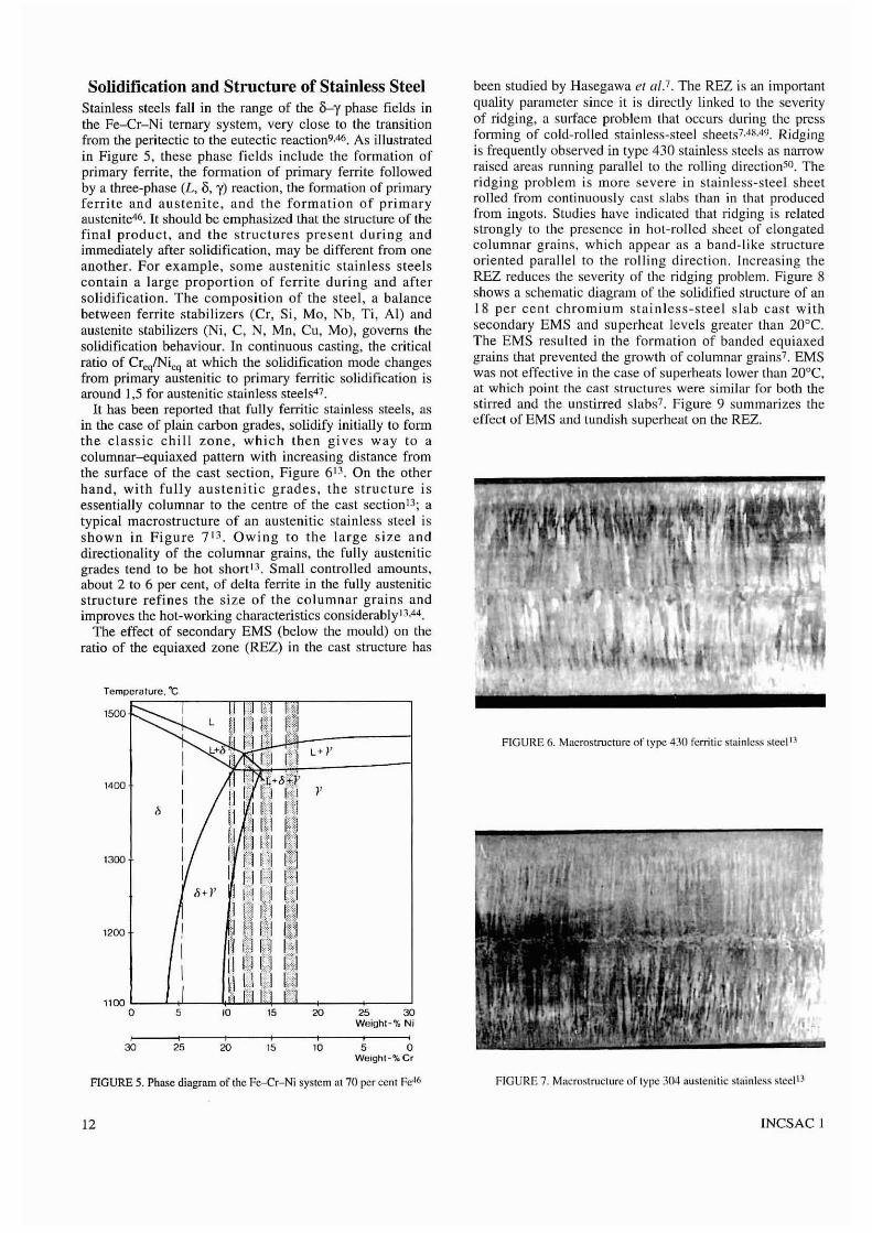
Solidification and Structure of Stainless SteelStainless steels fall in the range of the &--y phase fields inthe Fe-Cr-Ni tcrnary system, very close to the transitionfrom the peritectic to the eutectic reaction9A6. As illustratedin Figure 5, these phase fields include the formation ofprimary ferrite, the formation of primary ferrile followedby a three-phase (L, 8, y) reaction, the formation of primaryferrite and austenite, and the formation of primaryaustenite46 . It should be emphasized that the structure of thefinal product, and the structures present during andimmediately after solidification, may be different from oneanother. For example, some austenitic stainless steelscontain a large proportion of ferrite during and aftersolidification. The composition of the steel, a balancebetween ferrite stabilizers (Cr, Si, Mo, Nb, Ti, AI) andaustenite stabilizers (Ni, C, N, Mn, Cu, Moj, governs thesolidification behaviour. In continuous casting, the criticalratio of CreqINieq at which the solidification mode changesfrom primary austenitic to primary ferritic solidification isaround 1,5 for austenitic stainless steels47.
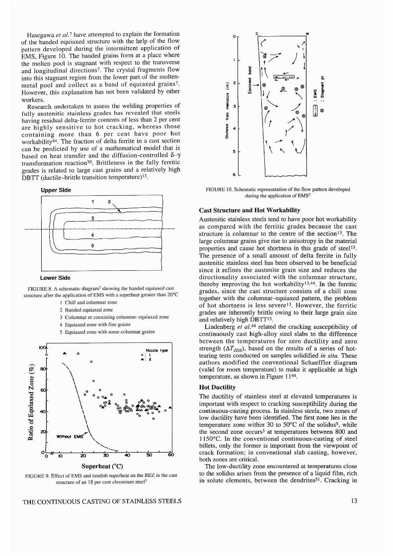
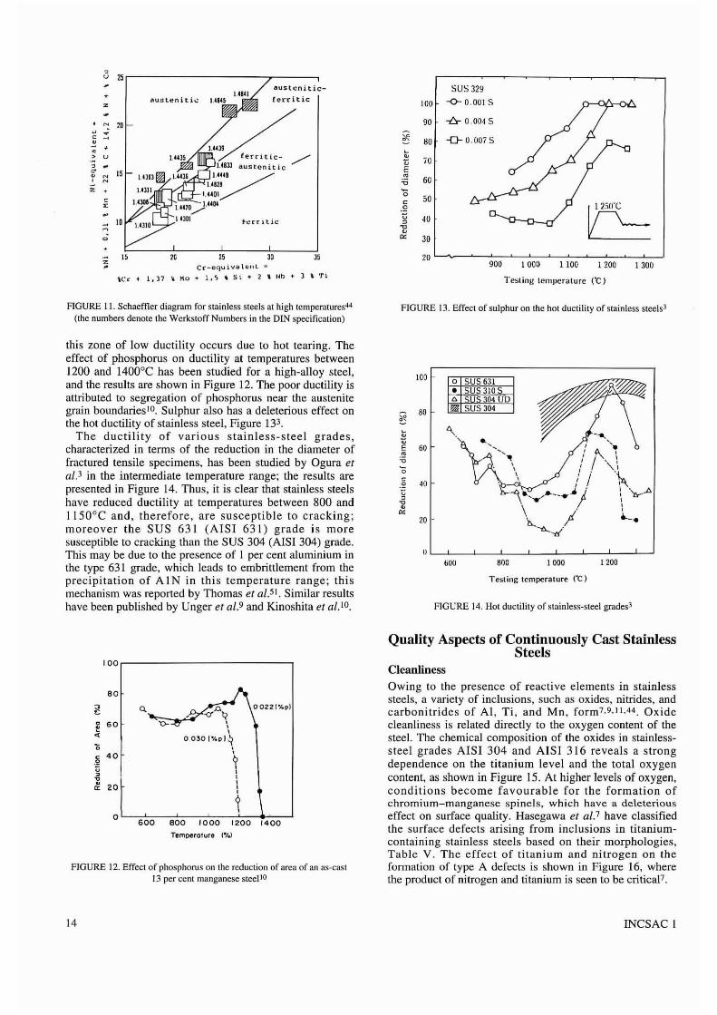
It has been reported that fully ferritic stainless steels, asin the case of plain carbon grades, solidify initially to formthe classic chill zone, which then gives way to acolumnar-equiaxed pattern with increasing distance fromthe surface of the cast sectjon, Figure 6 13. On the otherhand, with fully austenitic grades, the structure isessentially columnar to the centre of the cast section 13; atypical macrostructure of an austenitic stainless steel isshown in Figure 7 13 . Owing to the large size anddirectionality of the columnar grains, the fully austeniticgrades tend to be hot short l3 . Small controlled amounts.about 2 to 6 per cent, of delta ferrite in the fully austeniticstructure refines the size of the columnar grains andimproves the hot-working characteristics considerably13.44.
The effect of secondary EMS (below the mould) on theratio of the equiaxed zone (REZ) in the cast structure has
FIGURE 6. Macrostructure of tyflC 430 fcrritic stainless sleel 13
been studied by Hasegawa e/ (/1.'. The REZ is an importantquality parameter since it is directly linked to the severityof ridging, a surface problem that occurs during the press~orming of cold-rolled stainless-steel sheets7.4ii.4\). RidgingIS frequently observed in type 430 stainless steels as narrowraised areas running parallel to the rolling direclion5o. Theridging problem is more severe in stainless-steel sheetrolled from continuously cast slabs than in that producedfrom ingots. Studjes have indicated that ridging is relatedstrongly to the presence in hal-rolled sheet of elongatedcolumnar grains, which appear as a band-like structureoriented parallel to the rolling direction. Increasing theREZ reduces the severity of the ridging problem. Figure 8shows a schematic diagram of the solidified structure of an18 per cent chromium stainless-steel slab cast withsecondary EMS and superheat levels greater than 20°C.The EMS resulted in the formation of banded equiaxedgrains that prevented the growth of columnar grains? EMSwas not effective in the case of superheats lower than 20°C,at which point the cast structures were similar for both thestirred and the unstirred slabs7. Figure 9 summarizes theeffect of EMS and tundish superheat on the REZ.
5 10 15 20 25 30Weight-"/" Ni
I I ,25 20 15 10 5 0
Weighl-"1o Cr
1200
1500
1400
30
'300
FIGURE 5. Phase diagram of the Fe-Cr-Ni systcm at 70 per ccnt Fe46 FIGURE 7. Macrostructure of type 304 austenitic slllinlcss laeel B
12 INCSAC 1
Hasegawa el al.7 have attempted to explain the formationof the banded equiaxed structure with the help of the !lowpattern developed during the intermittent application ofEMS, Figure 10. The banded grains form at a place wherethe molten pool is stagnant with respect to the transverseand longitudinal directions? The crystal fragments flowinto this stagnant region from the lower part of the moltenmetal pool and collect as a band of equiaxed grains?However, this explanation has not been validated by otherworkers.
Research undertaken to assess the welding properties offully austenitic slain less grades has revealed that steelshaving residual delta-ferrite contents of less than 2 per centare highly sensitive to hot cracking, whereas thosecontaining more than 6 per cent have poor hotworkability44. The fraction of delta ferrite in a cast sectioncan be predicted by use of a mathematical model lhat isbased on heat transfer and the diffusion-controlled '6-ytransformation reaction5o. Brittleness in the fully ferriticgrades is related to large cast grains and a relatively highOBIT (ductile-brittle transition temperature)13.
Upper Side
3
- --f---'--~-------'-'-'-'-'-'-5
Lower Side
FIGURE 8. A schematic diagram? showing the banded equiaxed caststructure after the appliciltion of EMS wilh a superheat grealer lhun 20°C
I Chill and columnar ZOlle
2 Banded cquiaxcd zone
3 Columnar or coexisting colurnnur--equiaxcJ zone
4 Equiax.cd zone with fine grains
5 Equiax.ed zone with some (;olumnar grains
oof • 0Nozrle 1)PIll
0 0: I
0.. : I
~"-
\~ \'"" \ 00
N 00
'" 0 0 00...0 0
'" \.. \ 0>,2 o g 0""'0 0 O?"oS \ 0 ..0 g"~ t"eo.,"'tiIe:cr "" \ W 0
00 0 0
0
"" \.... \0
00
Wlfhout ....r\.."~ \ .....
"-030 ""0 lO 20
Superheat ('C)
FIGURE 9. Effect of EMS and lundish superheat on the REZ in the caslstruclure of an 18 per CCIlI chromium sleeP
THE CONTINUOUS CASTING OF STAlNLESS STEELS
00 w
( ,I','it~ ) I,/
jR t\ -'..... - ' .. "- 2 1 - -E O~ Ill>
Ill> Ill> I'~
1/ JP... ~
~~
'\ ~~ ~
I 3 Ill>'--.....~ mill>
~ (, Ill>
j .. r-;'\a
\ --- \J, \ "6
FIGURE 10. Schcmalic represenlation of lhe flow pattern developedJuring the application of EMS7
Cast Structure and Hot Workability
Austenitic stainless steels tend to have poor hot workabilityas compared with the ferritic grades because the caststructure is columnar to the centre of the section l3. Thelarge columnar grains give rise to anisotropy in the materialproperties and calise hot shortness in this grade of steeP3.The presence of a small amounl of delta ferrite in fullyaustenitic stainless steel has been observed to be beneficialsince it refines the austenite grain size and reduces thedirectionality associated with the columnar structure,thereby improving the hot workability I3,44. In the ferriticgrades, since the cast structure consists of a chill zonetogether with the columnar--equiaxed pattern, the problemof hot shortness is less severe 13. However, the ferriticgrades are inherently brittle owing to their large grain sizeand relatively high DBIT",
Lindenberg el al. 44 related the cracking susceptibility ofcontinuously cast high-alloy steel slabs to the differencebetween the temperatures for zero ductility and zerostrength (t1TZDS), based on the resulls of a series of hottearing tests conducted on samples solidified ill situ. Theseauthors modified the conventional Schaeffler diagram(valid for room temperature) to make it applicable at hightemperature, as shown in Figure I )44.
Hot Ductility
The ductility of stainless steel at elevated temperatures isimportant with respect to cracking susceptibility during thecontinuous-casting process. In stainless steels, two zones oflow ductility have been identified. The first zone lies in thetemperature zone within 30 to SO°C of the solidus9, whilethe second zone occurs3 at temperatures between 800 and) ISO°C. In the conventional continuous-casting of steelbillets, only the former is important from the viewpoint ofcrack formation; in conventional slab casting, however,both zones are critical.
The low-ductility zone encountered at temperatures closeto the solidus arises from the presence of a liquid film, richin solute elements, between the dendrites51 • Cracking in
13
Cc-cquiV/lII:"l\c.'c t 1,)7 ~ Ho -+ l,~ Ii ~i -+ 2' Ilb t ) .. Ti
-o-U.OU75
70 .
60
50
'0
30
4U
Testing lempcrature rC)
2U L-'-~-=~~=--~:-7:::-'-:-=:~--:-'-:c:---'900 1UOU 1 100 1 200 1 300
SUS 32'100 -0- 0.00) S
90 -fr (J.(J(J4 S
"
"ustcnitic_
3D
h:n llic
ferritlc-
25
U813 austeni.tic
I.
U
Y'um1.'(01
I mo.•••.•..!-U04IIJlII
"
lIU:.lLen I ti...::
I'
,u 25
+z
~ 10" ~c•• +> u, .~
~15,
Z
z
;:;<;
AGURE 11. Schacfflcr diagram for stainless steels at high tcmpcraturcs44
(the numbers denote the Wcrkstoff Numbers in the DIN specification)FIGURE 13. Effect of sulphur on the hot ductility of stainless steels]
Testins temperature ("C)
FIGURE 14. Hot ductjlity of stainless-slee! grades3
1I'-----'-_-J-_.L...._.L...._.L--_.L--~'-:-___J__'
60U 800 1 000 1 200
o SUS 631• SUS 3100.. 304 UD~ SUS 304
'\
100
g 80
."~ 60
'0'0.§ ·10U,'l:" 20
this zone of low ductility occurs due to hot tearing. Theeffect of phosphorus on ductility at temperatures between1200 and 14000 C has been studied for a high-alloy steel,and the results are shown in Figure 12. The poor ductility isattributed to segregation of phosphorus near the austenitegrain boundaries JO. Sulphur also has a deleterious effect onthe hot ductility of stainless steel, Figure 133,
The ductility of various stainless-steel grades,characterized in terms of the reduction in the diameter offractured tensile specimens, has been studied by Ogura eflIf.3 in the intermediate temperature range; the results arepresented in Figure 14. Thus, it is clear that stainless steelshave reduced ductility at temperatures between 800 andI I50°C and, therefore, are susceptible to cracking;moreover the SUS 631 (AISI 631) grade is moresusceptihle to cracking than the SUS 304 (AISI304) grade.This may be due to the presence of I per cent aluminium inthe type 631 grade, which leads to embrittlement from theprecipitation of Al N in this temperature range; thismechanism was reported by Thomas et af.5 l . Similar resultshave been published by Unger ef aU and Kinoshita ef al. lO.
Quality Aspects of Continuously Cast StainlessSteels
100
80
i! Q.-O''''~
0 60 "t>-• ,,~
0030[%pl~...~
40~,, ,
~ ,'" 20 ,,
~0
600 800 1000 1200 1400
Temperolure l~/.l
FIGURE 12. Effect of phosphorus on the reduction of area of an as-cast13 per cellI IllClllganese slee1 tO
Cleanliness
Owing to the presence of reactive elements in stainlesssteels, a variety of inclusions, such as oxides, nitrides, andcarbonitrides of AI, Ti, and Mn, form 7.9. 11 ,44. Oxidecleanliness is related directly to the oxygen content of thesteel. The chemical composition of the oxides in stainlesssteel grades AISI 304 and AISI 316 reveals a strongdependence on the titanium level and the total oxygencontent, as shown in Figure IS. At higher levels of oxygen,conditions become favourable for the formation ofchromium-manganese spinels, which have a deleteriouseffect on surface quality. Hasegawa et aU have classifiedthe surface defects arising from inclusions in titaniumcontaining stainless steels based on their morphologies,Table v. The effect of titanium and nitrogen on theformation of type A defects is shown in Figure 16, wherethe product of nitrogen and titanium is seen to be criticaP,
14 INCSAC I
rr .;onlon!: 0,019/0,021 "
"'0,-----",-----,,----,
°'--'---'-''--'-+-~~---'° 0.1 0,2 0,3 0," 0,5
FIGURE [5. Oxide composition as a function of the titanium and tolaloxygen contents of steel9
TABLEYINCLUSION -RELATED SURFACE DEFECTS IN TITANIUM-CONTAINING
GRADES?
Type Morphology
A Rough surface with clusters of subsurfaceblowholes filled with mould slag
B Clusters of alumina and titanium nitride
C Blowholes (not clustered) filled with mould slag
D Entrapped scum
oxides of chromium, manganese, silicon, and aluminium,with lengths up to 50 mm52
In horizontal casting, the problem of inclusions is lesssevere because of the direct mould-tundish coupling. Thedistribution of inclusions in the cast product is interestingbecause, owing to their low density, more inclusions arefound in the upper portions than in the lower part of thecast billet section53.54 . Water-model studies on horizontalmoulds have revealed forward flow in the lower regionsand reverse flow in the upper zone of the liquid pool in themoulds4 . The reverse flow apparently entrains inclusions ofalumina and titanium nitrides, which become entrapped bythe advancing solidification frontS4 .
OsciUation and Witness Marks
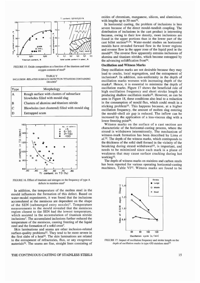
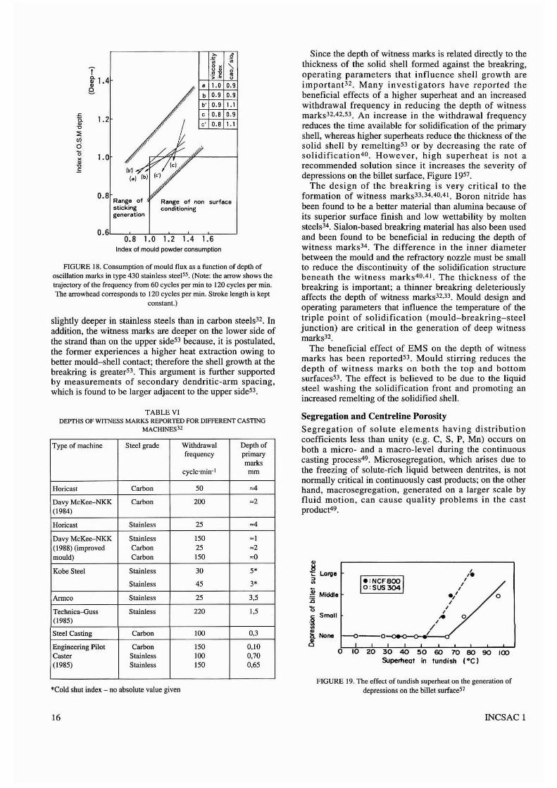
Deep oscillation marks are not desirable because they maylead to cracks, local segregation, and the entrapment ofinclusions8. In addition, non-uniformity in the depth ofoscillation marks worsens with increasing depth of themarks8 . Hence, it is essential to minimize the depth ofoscillation marks. Figure 17 shows the beneficial role ofhigh oscillation frequency and short stroke length inproducing shtillow oscillation rnarksS5 • However, as can beseen in Figure 18, these conditions also lead to a reductionin the consumption of mould flux, which could result in asticking problem55 . This happens because, at a higheroscillation frequency, the amount of molten slag enteringthe mould-shell air gap is reduced. The inflow can beincreased by the application of a less-viscous slag with alower freezing point56 .
Witness marks on the surface of a cast section arecharacteristic of the horizontal-casting process, where thestrand is withdrawn intermittently. The mechanism ofwitness-mark formation has been described by Lima etai. 32. The depth of the witness marks, which corresponds tothe thickness of the solid shell formed in the vicinity of thebreakring during strand withdrawal s3 , is important, andneeds to be minimized since each mark is a plane ofweakness that may cause surface cracking during hotworking32.
The depth of witness marks on stainless and carbon steelshas been reported for various operating horizontal-castingmachines, Table VP2. Witness marks are found to be
~ 80 100 120
Oscillation cycle (c/min)
FIGURE 17. Impact of oscillation frequency and stroke length on thedepth of oscillation marks in lype 430 stainless steel55
FIGURE 16. Effect of titanium and nitrogen on the frequency of type Adefects in stainless stee[1
In addition, the temperature of the molten steel in themould influences the formation of this defect. Based onwater-model experiments, it was found that the inclusionsaccumulated at the meniscus are dependent on the shapeof the SEN (submerged entry nozzle)'. Temperaturemeasurements in the mould revealed that the meniscusregion closest to the SEN had the lowest temperature,which assisted in the accumulation of titanium nitrideinclusions7 . The accumulated inclusions further reduced thetemperature of the meniscus, causing freezing of the liquidsteel and the formation of a solid crust7.
Skin laminations and seams are other inclusion-relatedsurface-quality problemsS2 • They tend to be more severe inthe first slabs of a heat52 . The skin laminations are relatedto the entrapment of refractories, flux, or any exogenousmaterials52 . The seams are fine, straight lines consisting of
T 1.4~••8-£ 1.2~
~
"ui 1.0o
~ 0.8E
Stroke
• Large
a Mlddla
)( Small
THE CONTINUOUS CASTING OF STAINLESS STEELS 15
*Cold shut index - no absolute value given
o
,,.,,,./,,,
,. 0,/--O-Q400--o-__--<f
~ Middle:0'0.~ Small
~a None
~
FIGURE 19. The effect of tundish superheat on the generation ofdepressions on the billet surfaceS7
o 10 20 30 40 50 60 10 80 90 100Supemeaf In fundish (·C)
Since the depth of witness marks is related directly to thethickness of the solid shell formed against the breakring,operating parameters that influence shell growth areimportant32 , Many investigators have reported thebeneficial effects of a higher superheat and an increasedwithdrawal frequency in reducing the depth of witnessmarks32.42,53, An increase in the withdrawal frequencyreduces the time available for solidification of the primaryshell, whereas higher superheats reduce the thickness of thesolid shell by remelting53 or by decreasing the rate ofsolidification 4o , However, high superheat is not arecommended solution since it increases the severity ofdepressions on the billet surface, Figure 195'.
The design of the hreakring is very critical to theformation of witness marks33 ,34.40.41, Boron nitride hasbeen found to be a better material than alumina because ofits superior surface finish and low wettability by moltensteels34. Sialon-hased breakring material has also been usedand been found to be beneficial in reducing the depth ofwitness marks34, The difference in the inner diameterbetween the mould and the refractory nozzle must be smallto reduce the discontinuity of the solidification structurebeneath the witness marks40.4l , The thickness of thebreakring is important; a thinner breakring deleteriouslyaffects the depth of witoess marks32.33 . Mould design andoperating parameters that influence the temperature of thetriple point of solidification (mould-breakring-steeljunction) are critical in the generation of deep witnessmarks32•
The beneficial effect of EMS on the depth of witnessmarks has been reported53 , Mould stirring reduces thedepth of witness marks on both the top and bottomsurfaces53 , The effect is believed to be due to the liquidsteel washing the solidification front and promoting anincreased remelting of the solidified shell.
Segregation and Centreline Porosity
Segregation of solute elements having distributioncoefficients less than unity (e.g. C, S, P, Mn) occurs onboth a micro- and a macro-level during the continuouscasting process49 , Microsegregation, which arises due tothe freezing of solute-rich liquid between dentrites, is notnormally critical in continuously cast products; on the otherhand, macrosegregation, generated on a larger scale byfluid motion, can cause quality problems in the castproduct49,
Range of non surfaceconditioning
Range ofstickinggeneration
0.8
.~ §• •
"1o < "-~ . 0
t 1.4":;: :2 ~
• 1.0 a.'e.b a.' a.'b' a.' 1.1
~ 1.2, 0.8 a.'
• " 0.8 1.1"::;<Ii0'0 1.0••"E
TABLE VIDEPTHS OF WITNESS MARKS REPORTED FOR DIFFERENT CASTING
MACHINES32
FIGURE 18. Consumption of mould flux as a function of depth ofoscillation marks in type 430 stainless slcel55. (Note: the arrow shows thetrajectory of the frequency from 60 cycles per min to 120 cycles per min.The arrowhead corresponds to 120 cycles per min. Stroke length is kept
constant.)
O. 6L-~;-;,'-;;----,-'-;;-""'----'--'-;-_---'0.8 1.0 1.2 1.4 1.6
Index 01 mould powder consumption
slightly deeper in stainless steels than in carbon steels32. Inaddition, the witness marks are deeper on the lower side ofthe strand than on the upper side53 because. it is postulated,the former experiences a higher heat extraction owing tobetter mould-shell contact; therefore the shell growth at thebreakring is greater53 . This argument is further supportedby measurements of secondary dendritic-arm spacing,which is found to be larger adjacent to the upper side53•
Type of machine Steel grade Withdrawal Depth offrequency primary
markscycle'min-! mm
HoricaSI Carbon 50 ...Davy McKee-NKK Carbon 200 -2(1984)
Horieast Stainless 25 ...Davy MeKee-NKK Stainless 150 -1(1988) (improved Carbon 25 ~2
mould) Carbon 150 ~O
Kobe Steel Stainless 30 5'
Stainless 45 3'
Armco Stainless 25 3,5
Technica-Guss Stainless 220 1,5(1985)
Steel Casting Carbon 100 0.3
Engineering Pilot Carbon 150 0.10Caster Stainless \00 0,70(1985) Stainless 150 0.65
16 INCSAC 1
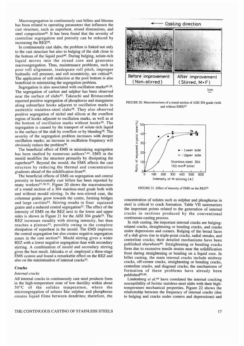
FIGURE 21. Effecl of inlensily of EMS on Ihe REZSJ
1cm
After improvement(Stirred, M+F)
••8N
(; 40
~b 30
~c5af
.~.
Before improvement( Non-stirred)
-- Casting direction
FIGURE 20. Macroslructures of a round section of AISI 304 grade (withand without EMS)SJ
concentration of solutes such as sulphur and phosphorus insteel is critical to crack formation. Table VU summarizesthe important points related to the generation of internalcracks in sections produced by the conventionalcontinuous-casting process.
In slab casting, the important internal cracks are bulgingrelated cracks, straightening or bending cracks, and cracksunder depressions and comers. Bulging of the broad facesof a slab gives rise to triple-point cracks, radial streaks, andcentreline cracks; their detailed mechanisms have beenpublished elsewhere60. Straightening or bending cracksform due to excessive tensile strains near the solidificationfront during straightening or bending on a liquid core. Inbillet casting, the main internal cracks include midwaycracks, off-corner cracks, straightening or bending cracks,centreline cracks, and diagonal cracks; the mechanisms offormation of these problems have already beenpublished59.60.
Lindenberg et al.44 have correlated the internal crackingsusceptibility of ferritic stainless-steel slabs with their hightemperature mechanical properties. Figure 22 shows therelationship between the frequency of internal cracks (dueto bulging and cracks under comers and depressions) and
'" 50)~-----------.
CracksInfernal cracks
AU internal cracks in continuously cast steel products formin the high-temperature zone of low ductility within about50°C of the solidus temperature, where themicrosegregation of solutes like sulphur and phosphoruscreates liquid films between dendrites; therefore, the
Macrosegregation in continuously cast billets and bloomshas been related to operating parameters that influence thecast structure, such as superheat, strand dimensions, andsteel composition49. It has been found that the severity ofcentreline segregation and porosity can be reduced byincreasing the REZ49.
In continuously cast slabs, the problem is linked not onlyto the cast structure but also to bulging of the slab close tothe bollom of the liquid poo149. During bulging, solute-richliquid moves into the strand core and generatesmacrosegregation. Thus, maintenance problems, such aspoor roll alignment. inadequate roll pitch, improperhydraulic roll pressure, and roll eccentricity, are critical49.
The application of soft reductioo at the pool bottom is alsobeneficial in minimizing the segregation problem.
Segregation is also associated with oscillation marks4s.s8 .The segregation of carbon and sulphur has beeo observednear the surface of slabs4s. Takeuchi and Brimacombereported positive segregation of phosphorus and manganesealong subsurface hooks adjacent to oscillation marks inaustenitic stainless-steel slabs". They also observedpositive segregation of nickel and silicon at the overflowregion of hooks adjacent to oscillation marks, as well as atthe bottom of oscillation marks without hooksS8 . Thesegregation is caused by the transport of solute-rich liquidto the surface of the slab by overflow or by bleeding'S. Theseverity of the segregation problem increases with deeperoscillation marks; an increase in oscillation frequency willobviously reduce the problem'S.
The beneficial effect of EMS in minimizing segregationhas been studied by numerous authors7.44. EMS in themould modifies the structure primarily by dissipating thesuperheat49. Beyond the mould, the EMS affects the caststructure by reducing the thermal and concentrationgradients ahead of the solidification front49.
The beneficial effects of EMS on segregation and centralporosity in horizontally cast billets has been reported bymany workers37.38.53. Figure 20 shows the macrostructureof a roond section of a 304 stainless-steel grade both withand without mould stirring. In the non-stirred case. thecolumnar grains grow towards the centre, forming bridgesand large cavities53 . Stirring results in finer equiaxedgrains and a reduced central segregation53. The effect of theintensity of EMS on the REZ oext to the lower and uppersides is shown in Figure 2 I for the A1SI 304 grade53. TheREZ increases steadily with stirring intensity, but thenreaches a plateau 53 , possibly owing to the completedissipation of superheat in the mould. The EMS improvesthe central segregation but also creates negative segregationzones in the cast sections3. Mould stirring gives a widerREZ with a lower negative segregation than with secondarystirring. A combination of mould and secondary stirringgives the best result. lshizaka el al. employed a three-stageEMS system and found a remarkable effect on the REZ andalso on the minimization of intemaJ CrdCks33.
THE CONTINUOUS CASTING OF STAINLESS STEELS 17
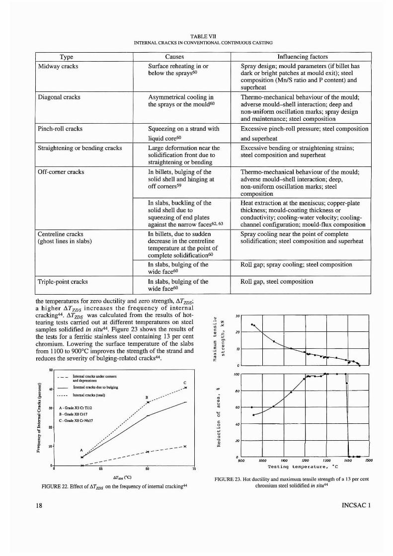
TABLE VIIINTERNAL CRACKS IN CONVENTIONAL CONTINUOUS CASTING
Type Causes Influencing factors
Midway cracks Surface reheating in or Spray design; mould parameters (if billet hasbelow the sprays60 dark or bright patches at mould exit); steel
composition (Mn/S ratio and P content) andsuperheat
Diagonal cracks Asymmetrical cooling in Thermo-mechanical behaviour of the mould;the sprays or the mould60 adverse mould-shell interaction; deep and
non-uniform oscillation marks; spray designand maintenance; steel composition
Pinch-roll cracks Squeezing on a strand with Excessive pinch-roll pressure; steel composition
liquid core6O and superheat
Straightening or bending cracks Large deformation near the Excessive bending or straightening strains;solidification front due to steel composition and superheatstraightening or bending
Off-corner cracks In billets, bulging of the Thermo-mechanical behaviour of the mould;solid shell and hinging at adverse mould-shell interaction; deep,off comers59 non-unifonn oscillation marks; steel
composition
In slabs, buckling of the Heat extraction at the meniscus; copper-platesolid shell due to thickness; mould-coating thickness orsqueezing of end plates conductivity; cooling-water velocity; cooling-against the narrow faces62• 63 channel configuration; mould-flux composition
Centreline cracks In billets, due to sudden Spray cooling near the point of complete(ghost lines in slabs) decrease in the centreline solidification; steel composition and superheat
temperature at the point ofcomplete solidification60
In slabs, bulging of the Roll gap; spray cooling; steel compositionwide face60
Triple-point cracks [n slabs, bulging of the Roll gap, steel compositionwide face60
Inlemal cn.c1a under <:omen-.nd ~prcSliof1l
C
I .. Inll:lIlai CriCks due to bulging ,0~
Inlernal cncks (loul)D •
~ ,0' •~ "
" A·CratleXSCr1i12 •U ,
~;; a·O"uk-X8Cr17
~ C·OndcX8CrNb17 c~ " .~0 ~
f00"0•
I 10 -" '"A ----~---
D0 " " "
o
"'"
'"~ -- --.,
iJ-....
the temperatures for zero ductility and zero strength, !:J.TZDS;
a higher !J.TZDS increases the frequency of internalcracking44. !J.TZDS was calculated from the results of hottearing tests carried out at different temperatures on steelsamples solidified in situ44 . Figure 23 shows the results ofthe tests for a ferritic stainless steel containing 13 per centchromium. Lowering the surface temperature of the slabsfrom 1100 to 900°C improves the strength of the strand andreduces the severity of bulging-related cracks44 .
",------------------------,
>~ z- "•c ,;.•~
~
E ~
0 ~E ""
~
• •~
JO
"
o
''''
"
"
/~
V./
.--V
1000 1100 /}Oo I Joe 1(00
Testing tempet"ature, ·C1500
t:.Tws("C)
FIGURE 22. Effect of !J.Tws on the frequency of internal cracking+4
18
FIGURE 23. Hot ductility and ma",imum tensile strength of a 13 per centchromium steel solidified ill sitlt«
INCSAC 1
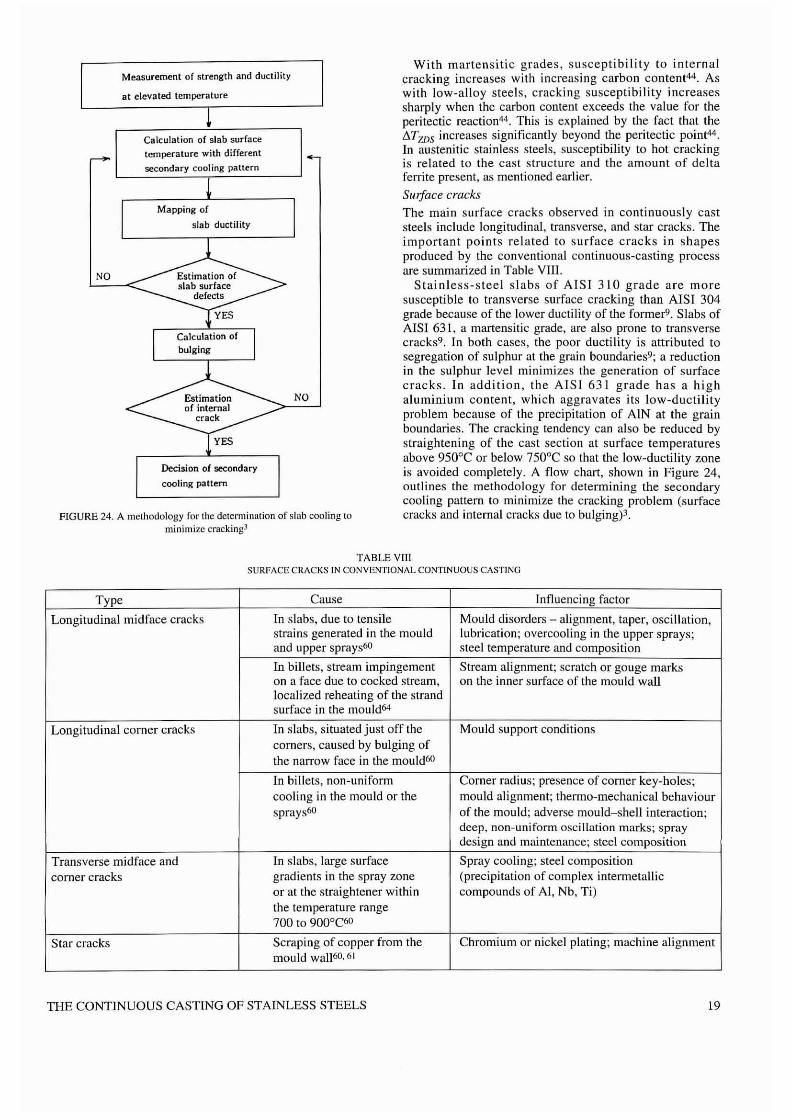
Measurement of strength and ductility
at elevated temperature
Calculation of slab surfacetemperature with different
secondary cooling paltern
Mapping of
slab ductility
NO
NO
YES
Decision of secondary
cooling pattern
FIGURE 24. A methodology ror the determination of slab cooling tominimize cracking]
With martensltlc grades, susceptibility to internalcracking increases with increasing carbon content44 • Aswith low-alloy steels, cracking susceptibility increasessharply when the carbon content exceeds the value for theperitectic reaction44 . This is explained by the fact that the!i.TZDS increases significantly beyond the peritectic point44 .
In austenitic stainless steels, susceptibility to hot crackingis related to the cast structure and the amount of deltaferrite present, as mentioned earl.ier.
Sluface cracks
The main surface cracks observed in continuously caststeels include longitudinal, transverse, and star cracks. Theimportant points related to surface cracks in shapesproduced by the conventional continuous-casting processare summarized in Table YIlI.
Stainless-steel slabs of AISI 310 grade are moresusceptible to transverse surface cracking than AISI 304grade because of the lower ductility of the former9. Slabs ofAISI 631, a martensilic grade, are also prone to transversecracks9 . In both cases, the poor ductility is attributed tosegregation of sulphur at the grain boundaries9; a reductionin the sulphur level minimizes Ihe generation of surfacecracks. In addition, the AISI 631 grade has a highaluminium content, which aggravates its low-ductilityproblem because of the precipitation of AIN at the grainboundaries. The cracking tendency can also be reduced bystraightening of the cast section at surface temperaturesabove 950°C or below 750°C so that the low-ductility zoneis avoided completely. A flow chart, shown in Figure 24,outlines the methodology for determining the secondarycooling pattern to minimize the cracking problem (surfacecracks and internal cracks due to bulgingp.
TABLE VtrlSURFACE C!lACKS IN CONVENTIONAL CONTLNUOUS CASTING
Type Cause Influencing factor
Longitudinalmidface cracks Tn slabs, due to tensile Mould disorders - alignment, taper, oscillation,strains generated in the mould lubrication; overcooling in the upper sprays;and upper sprays60 steel temperature and composition
In billets, stream impingement Stream alignment; scratch or gouge markson a face due to cocked stream, on the inner surface of the mould walllocalized reheating of the strandsurface in the mould64
Longitudinal corner cracks Tn slabs, situated just off the Mould support conditionscorners, caused by bulging ofthe narrow face in the mould60
In billets, non-uniform Corner radius; presence of corner key-holes;cooling in the mould or the mould alignment; thermo-mechanical behavioursprays60 of the mould; adverse mould-shell interaction;
decp. non-uniform oscillation marks; spraydesign and maintenance; steel composition
Transverse midface and In slabs, large surface Spray cooling; steel compositioncomer cracks gradients in the spray zone (precipitation of complex intermetallic
or at the straightener within compounds of AI, Nb, Ti)the temperature range700 to 900°C60
Star cracks Scrapi ng of copper from the Chromium or nickel plating; machine alignmentmould wall60,61
THE CONTINUOUS CASTING OF STAINLESS STEELS 19
In conventionally cast slabs, the transverse cracks aregenerated in the secondary-cooling zone, or beyond it, atthe straightener owing to embrinlement at lowertemperatures caused by precipitation of compounds such asAIN, Ti(C,N) etc.3.60. In conventionally cast billets, thetransverse cracks are related to sticking or binding in themould61 . In horizontally cast steel billets, transverse cracksare observed in the vicinity of the witness marks and arerelated to the pull time34 ; the mechanism in the generationof transverse cracks has been described by Nakai el al.,who propose that there is a critical shell thickness belowwhich transverse cracks form 34 • A reduction in the pulltime or the introduction of a 'push-back' step in the cycleleads to the formation of a thicker sbell and thereforeminimizes the problem of transverse cracks34 .
Longitudinal cracks in conventionally cast slabs arerelated to the nature of the mould-sbell interaction, whichdepends on mould cooling, taper, and lubrication. The roleof mould lubrication in the generation of this qualityproblem is significant. In stainless steels, particularly thosecontaining aluminium and titanium, the composition of themould flux changes significantly during the casting of aheat3. For example, during the casting of the AISI 631grade, which contains about I per cent aluminium, thesoftening temperature of the molten flux increases withincreasing slag basicity because of chemical interactionbetween the mould flux and the molten steel3. Aluminiumin the molten steel reduces tbe SiO, content of the mouldflux and therefore increases its basicity3. The highfrequency of longitudinal cracks has also been linked to themelting rate of the mould flux, which is related to themorphology of the carbon in it45 .
In conventionally cast billets, longitudinal comer cracksare generated because of non-unifonn cooling in the cornerregions of the mould, which are often caused by anexcessive corner radius. Longitudinal surface cracks havebeen observed in rounds cast by the horizontal-castingprocessS3 . These cracks originate from non-uniform shellgrowth in the mould53. Mould stirring has a beneficialeffect since it enhances the formation of a uniform solidsheIls3; increasing the intensity of mould stirring reducesthe frequency of the cracking problem53.
Star cracks in conventionally cast slabs arise due to thescraping of copper from the mould walls60,63. The copperpenetrates the slab surface and causes hot shortness inlocalized regions. These cracks are roughly 1,5 to 3,0 mmdeep and appear in clusters in the pattern of a star60 .
Chromium plating of the copper mould prevents tbepenetration of copper into the slabs and therefore eliminatesstar crack.s60. Nakano el al. have found that precipitationhardened copper moulds baving a layer of electroforrnednickel (about 3 mm thick) increase the grinding yield of theslabs and improve the mould life; this happens because thenickel layer reduces mould wear63.
Depressions
Longitudinal depressions
Longitudinal depressions, 2 to 5 mm deep, have beenobserved on the broad face of conventionally cast type 304stainless-steel slabs at off-corner locations 61 • They areassociated with bulging of the. narrow face or are caused bybuckling of the solid shell resulting from squeezing of theend plates against the narrow faces6 1.62 • Buckling of the
20
solid shell at the off-corner of the broad faces generates atensile strain close to the solidification front and asubsurface crack; therefore, it is common to find a crackbelow or at the base of a surface depression. A similarmechanism has been proposed for the generation of offcorner internal cracks in billelsS9.
The formation of longitudinal depressions in slabs basbeen related to the behaviour of the slag rim at themeniscus; proper heat-flow conditions near the meniscuswill belp minimize this quality problem6'. Mahapatra eta1.62 have found that variables important for controlling theheat eXlrdction at the meniscus are copper-plate thickness,mould-coating thickness or conductivity, cooling-watervelocity, cooling-channel configuration, and mould-fluxcomposition.
Transverse depressions
Transverse depressions have been observed in AISI 304,316, and 321 grades, being more severe in the 304 steel65 •
On the other hand, in resulphurized type 304 and 316grades, transverse depressions are not a problem; simUarbehaviour is exhibited by 0, I per cent carbon steelscontaining high levels of sulphurM.
Wolf has attributed the formation of transversedepressions in austenitic stainless steels and plain carbonsteels to local overcooling of the strand during initialsolidification that is followed by contraction due to 'plastichinge effect' and rebending6S . Austenitic stainless steelswith Creq/Nicq around 0,55 tend to be sensitive to theformation of depressions because of a large local shrinkageassociated with the 8-y transformation at the end ofsolidification; this phenomenon is very similar to thatobserved in 0.1 per cent plain carbon steels6s. However,this theory may not adequately explain the generation ofsurface or subsurface cracks bclow these depressions.Samarasekera and Brimacombe66 postulate that transversedepressions in billet casting are relaled to sticking orbinding in the mould as a result of which the withdrawalsystem pulls the strand and generates longitudinal tensilestresses and slrains. Depending on lhe magnitude of thestress, the solid shell may flow plasticly and form adepression 011 the billet surface (similar to necking in atensile test)66.
Examination of the shell below a transverse depression inaustenitic stainless steel revealed a zone of locally reducedheat flow and retarded shell growth65 . A local enrichmentin ferrite at the depression site was also observed65 . Asmentioned earlier, excessive ferrite is not desirable inaustenitic steel since it lowers its hot workability.
In billet casting, transverse depressions can be minimizedby operating with proper taper, lubrication, and oscillationcharacteristics; the thermomechanical behaviour of themould, i.e. excessive distortion, may also cause adversemould-shell interaction 6? According 10 Wolf, Ibefrequency of depressions can be reduced by ensuring a lowheat flux near the meniscus, which produces a thinnerinitial shell; he has suggested that this condition can beachieved by operating wirh higher casting speeds, highersuperheats, and an optimum slag-film stability,corresponding to minimum heat flux and friction6s. Theapplication of soft mould cooling with the belp of a hot topmould has also been proposed by the same author as apotential method to reduce depressions in austeniticsteels6s.
INCSAC I
AcknowledgmentsThe authors are grateful to the Canadian steel industry andthe Natural Sciences and Engineering Research Council ofCanada for supporting work on continuous casting.
ReferencesI. Harabuchi, T.B. and Phclke, R.D. (1988). Design and
operations. Continuous castillg. vol. 4, ISS-AIME,Warrendale, PA.
2. Brimacombe, J.K. and Samarasckera, LV. (1988).Fundamental analysis of the continuous casting processfor quality improvements. Proceedings of II/do-USWorkshop 011 Principles of Solidification alld MaterialsProcessillg, Hyderabad, Illdia, Oxford and IBHPublishing Company, New Delhi, India, pp. 179-222.
3. Ogura, S., Kawaharada. A.. Matsuzaki, M., Kityaoka,H. and Ohtsubo, H. (1986). Production of high gradestainless steel, Kawasaki Technical Report, 14, pp.23-30.
4. Spaccarotella, A .• Morelli, R., Dischino, G. andProvantini, G. (1985). Influence of mould oscillationand powder lubrication on surface quality of austeniticstainless steel slabs at Terni Works. Continuous Castillg'85. Institute of Metals, London, pp. 42.1-42.1 I.
5. Van Wijngaarden, MJ.U.T., Van den Heever, P.M. andLouw, T.A. (1990). The production of high-quality steelin a continuous billel casting operation. 73rdSteelmaking Conference Proceedings. ISS. Warrendale,PA, pp. 213-219.
6. Shimizu, S., Imada, Y.• Ishikawa, S., Kihara, K. andFutamura, T. (1990). Improvement of productivity inbillet continuous casting of stainless steel. 6thInternational Iron anti Steel Congress Proceedings,Nagoya, ISU, Japan, 3, pp. 487-493.
7. Hasegawa. M., Maruhashi, S.. Muranaka, Y., Kawai, Y.and Hoshi, H. (1982). Current status of qualityimprovement in continuous casting of stainless steelslabs. 40th Electric Furnace Proceedings, pp. 357-365.
8. Nakato, H.. Nozaki, T., Ogura, S. aod Morishila, H.(1986). New equipment for improvemcnt of stainlesssteel casting quality. Kawasaki Steel Technical Report,14, pp. 37-44.
9. Unger, K.D., Biesterfeld. W., Berentzen, F. andThielmann, R. (1985). Metallurgical problemsencountered in stainless steel continuous casting.Continllous Casting '85, Institute of Metals, London,pp. 61.l--{j I.7.
10. Kinoshita, K., Yoshii, Y., Kilaoka, H. and Kawaharada,A. (1984). Continuous casting of high-alloy steels.Journal ofMetals, 36, (3), pp. 38-43.
II. Vonesh, F. A. and Schmel, R. F. (1987). Inert gasshrouding of molten metal streams. Iron and SteelEngineer. 64. (7), pp. 35-43.
12. Metals Haudbook, vol. I, Properties and selection ofirons, steels, and high performance alloys (1990). ASM[ntemational, Mctals Park, Ohio, USA, pp. 841-930.
13. Ardito, V.P. and Walsh, R.A. (1981). Problems in thecasting of stainless and high alloy steels. 2nd ProcessTechnology Conference, COll1inUOliS Casting of Steel,ISS-AlME. Warrendale, PA. pp. 18D-187.
THE CONTINUOUS CASTING OF STAINLESS STEELS
14. Continuous Caster Roundup - United States andCaoada. (1991). Iroll and SteelmakeI', 18, (I I), pp.16-31.
15. Hlady, e.O. (1991). Continuous casting of stainlesssteel. Internal Report. Centre for Metallurgical ProcessEngineering, University of British Columbia,Vancouver. Canada.
16. Grubb, J. F., Love, D. B., Murphy, A. and Nauman, J.D. (1986). Casting speciality steel strip. 69thSteelmaking COllferellce Proceedillgs, ISS, Warrendale,PA, pp. 841--S47.
17. Love: D. B. and Nauman, J. D. (1988) Controlling thephySical and mechanical properties of cast stainlesssteel band. Casting of near-net shape products,Metallurgical Society, Warrendale, PA, pp. 597--{j11.
18. Dean, D. e. (1988). The physical metallurgy of stripcast type 304 stainless steel. Iroll alld SteelmakeI' 15(3), pp. 12-15. ' ,
19. Nauman, J. D. and Love, D. B. (1986). The mechanicalprocessing of cast stainless steel strip. Mechanicalworking and steel processing, XXN. ISS, Warrendale,PA, pp. 2 I3-220.
20. Yoshida, C., Yasunaka, H., Nakagawa, T., Koyama, S.and Nozaki, S. (1988). Development of twin-roll stripcaster and metallurgical aspects of stainless steel. 4thInternational Conference on Continuous Casting. 2,Belgium.
21. Yamauchi, T., Nakanori, T., Hasegawa, M., Yabuki, T.and Ohnishi, N. (1988). Strip casting of stainless steelsby twin-rolls. 71st Steelmaking COllferenceProceedings, ISS. Warrendale, PA. pp. 161-165.
22. Apelian, D. and Ozgu, M. R. (1988). Direct casting ofthlI1 steel sections - a tutorial review. Modelling ofcasting and welding processes rv. eds. A. F. Giameiand G. J. Abbaschian, Mineral. Metals and MaterialSociety, Warrendale, PA, pp. 229-243.
23. Ozawa, M., Kogiku, F., Yukumolo, M., Miyake, S. andKan, T. (1988). Heat transfer analysis of twio-rollcasting. Ibid., pp. 255-263.
24. Brimacombe, J. K., Samarasekera, l. V. and Lair, J. E.(1984). Heat flow, solidification and crack formation.COlltilluous castillg, vol. 2, ISS-AI ME, Warrendale, PA.
25. Continuous casting of steel blooms and slabs, voJ. I,course notes, (1990). Centre for Metallurgical ProcessEngineering. University of British Columbia,Vancouver, Canada.
26. Ibid., (1990), vol. 2.27. Ibid., vols. I and 2.
28. Mabuchi, M., Nozaki, T., Habu, Y. and Yoshii, Y.(1986). Development of tundish heating system and itsapplication to stainless steel casting. 69th SteelmakillgConference Proceedings, l55, Warrendale, PA pp.737-742. •
29. Martinez, E., Maeda, M., Heaslip, L. 1., Rodriguez, G.and McLean, A. (1986). Effects of fluid flow on theinclusion separation in continuous casting tundish.Transactions ISIJ, 26, pp. 724-731.
30. Yamada, K., Watanabe, T., Fukuda, K., Kawaragi, T.and Tashlfo, T. (1987). Removal of non-metallicinclusion by ceramic filter. Transactions ISIJ, 27 pp.873-877. '
21
3l.Cummings, M. A. and McPherson, S.C. (1988).Application of ceramic foam filters in continuouscasting. 46th Electric FUrf/ace Conference Proceedings,ISS, Warrendale, PA, pp. 445-452.
32. Lima, J. E. R., Brimacombe. J. K. and Samarasekera, I.V. (1991) Mould heat transfer and solidification duringhorizontal continuous casting. lronmaking GndSteelmakillg, 18, pp. 114-127.
33.lshizaka, A., Tawara, M., Jchihashi, H., Kodama, H.and Tsujita, S. (1990). Production of billets for stainlesssteel seamless tubes by a horizontal continuous castingprocess. 6th International Iron and Steel Congress,Nagoya, ISIJ, Japan, 3, pp. 676-683.
34. Nakai, K., Umeda, Y., Sugitani, Y. and Miura, M.(1984). Effects of factors on the stability of casting inhorizontal continuous casting. Transactions ISIJ, 24,pp. 983-988.
35. Hentrich, R., Shanma, D. L., Dittert, D. and Roller, E.(1986). The horizontal casting of high-alloy steels usingthe Krupp oscillating mold process. Iron andSteelmaker, 13, (4), pp. 34-41.
36. Zalner, A. J. and Taylor, S. E. (1985). Horizontalcontinuous casting of stainless steel at Armco'sBaltimore Works. Iroll alld Steel Ellgilleer, 62, (2), pp.37-44.
37.Jones, D. N. and Henderson, S. (1989). Thedevelopment of horizontal continuous casting at BritishSteel Stainless. 47th Electric Furnace ConferencePraceedings, ISS, Wanendale, PA, pp. 73-78.
38. Machner, P., Reisl, E., Tarmann, R., Holleis, G. andPolanschuetz, W. (1986). Horizontal continuous castingtechnology for special steels. Iron and Steelmaker, 13,(4), pp. 15-18.
39. Zalner, A. J., and Taylor, S. E. (1986). Recent advancesof speciality in horizontal continuous casting. SteelTimes, 214, (10), pp. 550-552.
40. Heard, R. A. and McLean, A. (1988). Horizontalcontinuous casting. Conril/./lOus Casting, vol. 5, ISSAIME, Warrendale, PA.
41.1shihara, K., Sakane, T., Umeda, Y., Sugitani, Y. andNakai, K. (1980). Development of the horizontalcontinuous casting process for round stainless steelbillets. 38th Electric Furnace Conference Proceedings,ISS, Warrendale, PA, pp. 235-244.
42. Haissig, M. (1988). Horizontal continuous casting: Atechnology for the future. COllfinuuus casting, vol. 5,ISS, Warrendale, PA, pp. 13-19.
43.Saitoh, T., Hojo, H., Yagllchi, H., Kang, C. G. (1989).Two dimensional model for twin-roll continuouscasting. Melllllurgical Transactions B. 20B, 1989. pp.381-390.
44. Lindenberg, H., Loh, J. and Knackstedt, W. (1985).Quality aspects of change-over of high-alloyed specialsteels for flat products to continuous casting process.COll1inllOIlS Casting '85. Institute of Metals. London.pp. 40.1-40. \4.
45. Lindenberg, H. and Loh, J. (1986). Interactions betweencontinuous casting powders and high-alloyed steels operational results and laboratory tests. 69thSteelmaking Conference Proceedings, ISS. Warrendale,PA, pp. 161-167.
22
46.A guide to the solidificatiall af steels. (1977).Jernkontoret, Stockholm, Sweden, pp. 81-132.
47. Suutala, N. (1983). Effect of solidification conditionson the solidification mode in austenitic stainless steels.Metallurgical Transactions A, 14A, pp. 191-197.
48. Ashiura, T., Uchida, S., Koyasu, Y., Izumi, S., and Hoh,Y. (1981). Ridging properties of type 43-9 steel sheetsrolled from slabs produced by improved castingpractices. 2nd Process Technology Conference,Calltilluous Castillg of Steel, ISS-AIME, Warrendale,PA, pp. 166-174.
49. Lait, J. E. and Brimacombe, J. K. (1982). Solidificationduring continuous casting of steel. ISS Transactions, I,pp. 1-13.
50.Laki, R. S., Beech, J. and Davies, G. J. (1985).Prediction of dendritic arm spacings and delta-ferritefractions in continuously cast stainless steel slabs.lronmakin8 and Steelmaking, 12, pp. 233-241.
51. Thomas, B. G., Brimacombe, J. K. and Samarasekera, I.V. (1986). The formation of panel cracks in steel ingots:A state-of-the-art review, Part T, Hot ductility of steel.ISS TrallSllctiolls, 7, pp. 7-20.
52.0bman, A. R., Gennanoski, W. T. and Sussman, R. c.,(1981). Surface and subsurface defects on stainless steelfirst slabs. 2nd Process Technology Conference,Continuous Casting of STeel, ISS-AIME, Warrendale,PA, pp. 175-179.
53. Ayata, K., Nakata, H., Miyazaki, J., Nozakj, T. andMori, T. (1985) Development of horizontal continuouscaster for steel billets. 68th Steelmaking ConferenceProceedillg.>, ISS, Warrendale, PA, pp. 463-470.
54. Besedina, E. B., Mikhailova, I. V., Maslenkova, S. B.and Shatagin, O. A. (1988). Non-metallic inclusions instrands cast on horizontal continuous-cast machines.Continuous Casting, vol. 5, ISS Warrendale, PA, pp.113-115.
55. Kuwano, T., Shigematsu, N., Hsohi, F. and Ogiwara. H.(1982). Metallurgical problems encountered in thecontinuous casting of stainless steels. 4th Intema!ioflalIron and Steel Institute Conference, Metal Society,London, pp. 8.1-8.14.
56. Nakato, H., Nozaki, T., Habu, T., Oka, H., Ueda, T. andKitano, Y. (1985). Improvement of surface quality ofcontinuously cast slabs by high-frequency mouldoscillation. 68th Steelmaking Conference Proceedings,ISS, Warrendale, PA, pp. 361-365.
57.Sakane, T., Kodama, H.. Kiyoto, H.. Sugitani, Y. andHiraki, S. (1986). Production of stainless steel and highnickel alloys by the horizontal continuous castingprocess. lroll alld Steeill/aker, 13, (4), pp. 19-23.
58. Tackeuchi, E. and Brimacombe, J. K. (1985). Effect ofoscillation mark formation on the surface quality ofcontinuously cast steel slabs. MetallurgicalTransaction.> B, 16B, pp. 605-625.
59. Bommaraju, R., Brimacombe, J. K. and Samarasekera,I. V. (1984). Mould behaviour and solidification in thecontinuous casting of steel billets. Part III: Structure,solidification. crack formation and off-squareness. ISSTransactions,S, PI'. 95~105.
INCSAC I
60. Brimacombe, J. K. and Sorimachi, K. (1977). Crackformation in the continuous casting of steel.Metallllrgical Transactions B, 8B, pp. 489-505.
61. Thomas, B. G. (1989). Application of mathematicalmodels to the continuous slab casting mould. Iron andSteelmaker, 16, pp. 1-14.
62. Mahapatra, R. B., Brimacombe, J. K. andSamarasekera,l. V. (1991). Mould behaviour and itsinfluence on product quality in the continuous castingof slabs - II. Mould heat transfer, mould flux behaviour,formation of oscillation marks, longitudinal depressionsand sub-surface cracks. Subntilted to MetallllrgicalTransactions B.
63. Nakano, Y., Noguchi, Y., Hoshi, F. and Muranaka, Y.(1977). Continuous casting of stainless steels slabs.Continllolls casting of steel, Metals Society, London,pp.273-279.
THE CONTINUOUS CASTING OF STAINLESS STEELS
64. Kumar, S. (1991). An expert system to diagnose qualityproblems in the continuous casting of steel billets.M.A.Sc. thesis, University of British Columbia,Vancouver, Canada.
65. Wolf, M. (1986). Strand surface quality of austeniticsteels: Part I. Macroscopic shell growth and ferritedistribution. IrolJmakillg and Steelmaking, 13. pp.248-257.
66.Samarasekera, I. V. and Brimacombe, J. K. (1988).Heat extraction capability of continuous casting billetmould. W. O. Phi/brook Memorial SymposiumProceedings, ISS, Warrendale, PA, pp. 157-171.
67. Brimacombe, J. K. and Samarasekera, 1. V. (1986).Optimum design and operation of moulds for thecontinuous casti.ng of steel billets. 69th SteelmakingProceedings, ISS, Warrendale, PA, pp. 409-423.
23