Embed Size (px)
Citation preview

PDHonline Course S226 (8 PDH)
The Construction and Design ofConcrete Slabs on Grade
2012
Instructor: Matthew Stuart, PE, SE
PDH Online | PDH Center5272 Meadow Estates Drive
Fairfax, VA 22030-6658Phone & Fax: 703-988-0088
www.PDHonline.orgwww.PDHcenter.com
An Approved Continuing Education Provider

www.PDHcenter.com PDH Course S226 www.PDHonline.org
© D. Matthew Stuart Page 2 of 36
The Construction and Design of Concrete Slabs on Grade
D. Matthew Stuart, P.E., S.E., F.ASCE, SECB
COURSE CONTENT Slab on Grades
Construction:
Introduction
Concrete slabs on grade are a very common type of concrete construction. Floor slabs can range from a simple residential basement slab to a heavy-duty industrial floor. However, no matter how basic or complex the floor is, the construction method is similar and includes; preparing the sub-grade and sub-base, placing the reinforcement and concrete, and finishing and curing the slab. The quality of a completed floor slab is dependent on; an appropriate design, the quality of the materials used and the knowledge and experience of the workmen who place and finish the concrete. Other considerations that play a role in the successful construction of a slab on grade include; proper proportioning of the concrete mix, joint design and performance, and the slab thickness. Floor Classifications
Table 1 describes the nine classes of concrete floors according to ACI 302, Guide to Concrete Floor and Slab Construction. This table details some of the special considerations and finishing techniques that are appropriate for each class of floor. Within each class, unique factors such as local sub-grade conditions, locally available materials, and the placement environment should be considered for each individual design. Large concrete floors for commercial and industrial buildings must be designed and constructed using the greatest possible economy that results in a serviceable slab for the anticipated service life of the slab. To accomplish this goal, the construction of floor slabs requires close communication between the owner, architect, engineer, contractor and material supplier. The expectations and responsibilities of each participant should be established at a pre-design, pre-bid, and pre-construction meeting. At the pre-design meeting, the owner/user should answer the following questions:
1. How will the floor be used? 2. What types and magnitudes of floor loadings are anticipated?
3. What are the aesthetic requirements of the finish, including acceptability of random slab cracking?
4. Will floor coverings, coatings, or special toppings be used?
The design and construction of concrete floors on ground does not need to be a complicated procedure. However, the process should be based on the unique project specific variables involved. Factors such as soil conditions, anticipated loading, weather conditions during construction, and the properties of locally available materials all influence the appearance and serviceability of a floor slab. While a specific design

www.PDHcenter.com PDH Course S226 www.PDHonline.org
© D. Matthew Stuart Page 3 of 36
may work well in one situation, the same design or construction methods may not achieve the same results on another project. Even when the expected loading or use is identical, other factors are not likely to remain consistent, therefore each project should be evaluated separately.
TABLE 1

www.PDHcenter.com PDH Course S226 www.PDHonline.org
© D. Matthew Stuart Page 4 of 36
Floor Performance Criteria Many concrete floors built today can be highly complex with significant demands placed on them. For example, new warehouse facilities are often designed for high-density storage. This means the facility could potentially experience tall rack post and other extremely heavy loads, or require very restrictive floor flatness and levelness criteria to assure the proper operation of the equipment that stores and moves goods. As a result, floors can account for more complaints than any other part of a building, primarily because they are so critical to the proper use and operation of the building and also because any problems that develop are so readily exposed to view. To address this situation, careful attention must be given to the many factors that influence floor performance which include:
1. Uniformity of the sub-grade and adequacy of its bearing capacity. 2. Moisture content of the sub-grade and sub-base.
3. Quality of the concrete (particularly shrinkage potential).
4. Adequacy of the structural capacity.
5. Surface levelness and flatness.
6. Deformations (i.e. settlement) under applied loads.
7. Load transfer at the control and construction joints.
8. Type and spacing of the control and construction joints.
9. Workmanship and jobsite conditions.
10. Sub-slab details (i.e. vapor retarders - some times referred to as vapor barriers, insulation, etc.,).
11. Concrete moisture conditions and drying rate.
12. Special surface finishes, including coatings.
13. Adequacy of curing.
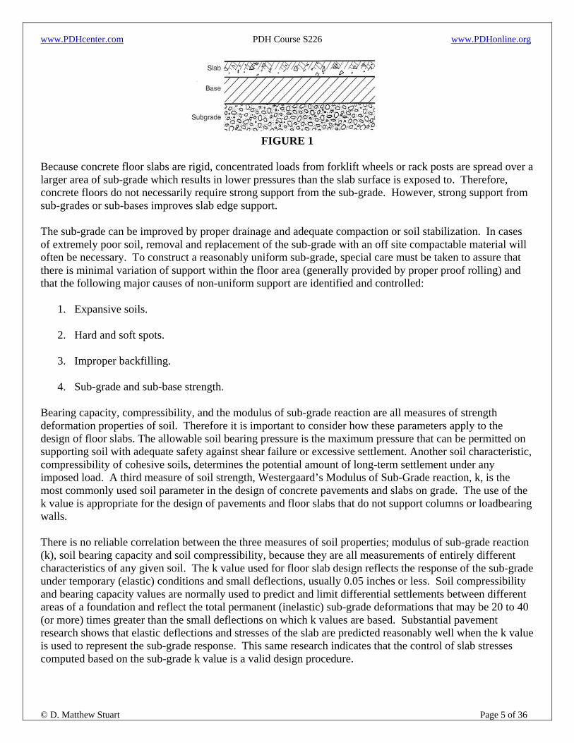
Sub-Grade and Sub-Base The sub-grade is the ground on which the floor is built. The sub-base is an optional layer located on top of the sub-grade and beneath the slab bottom (see Figure 1). The sub-base, while not mandatory, can provide added benefits to the construction and performance of the slab. It is vital to consider sub-grade preparation during design and construction to assure that the concrete floor will carry the intended loads successfully and without significant settlement.
www.PDHcenter.com PDH Course S226 www.PDHonline.org
© D. Matthew Stuart Page 5 of 36
FIGURE 1
Because concrete floor slabs are rigid, concentrated loads from forklift wheels or rack posts are spread over a larger area of sub-grade which results in lower pressures than the slab surface is exposed to. Therefore, concrete floors do not necessarily require strong support from the sub-grade. However, strong support from sub-grades or sub-bases improves slab edge support. The sub-grade can be improved by proper drainage and adequate compaction or soil stabilization. In cases of extremely poor soil, removal and replacement of the sub-grade with an off site compactable material will often be necessary. To construct a reasonably uniform sub-grade, special care must be taken to assure that there is minimal variation of support within the floor area (generally provided by proper proof rolling) and that the following major causes of non-uniform support are identified and controlled:
1. Expansive soils. 2. Hard and soft spots.
3. Improper backfilling.
4. Sub-grade and sub-base strength.
Bearing capacity, compressibility, and the modulus of sub-grade reaction are all measures of strength deformation properties of soil. Therefore it is important to consider how these parameters apply to the design of floor slabs. The allowable soil bearing pressure is the maximum pressure that can be permitted on supporting soil with adequate safety against shear failure or excessive settlement. Another soil characteristic, compressibility of cohesive soils, determines the potential amount of long-term settlement under any imposed load. A third measure of soil strength, Westergaard’s Modulus of Sub-Grade reaction, k, is the most commonly used soil parameter in the design of concrete pavements and slabs on grade. The use of the k value is appropriate for the design of pavements and floor slabs that do not support columns or loadbearing walls. There is no reliable correlation between the three measures of soil properties; modulus of sub-grade reaction (k), soil bearing capacity and soil compressibility, because they are all measurements of entirely different characteristics of any given soil. The k value used for floor slab design reflects the response of the sub-grade under temporary (elastic) conditions and small deflections, usually 0.05 inches or less. Soil compressibility and bearing capacity values are normally used to predict and limit differential settlements between different areas of a foundation and reflect the total permanent (inelastic) sub-grade deformations that may be 20 to 40 (or more) times greater than the small deflections on which k values are based. Substantial pavement research shows that elastic deflections and stresses of the slab are predicted reasonably well when the k value is used to represent the sub-grade response. This same research indicates that the control of slab stresses computed based on the sub-grade k value is a valid design procedure.

www.PDHcenter.com PDH Course S226 www.PDHonline.org
© D. Matthew Stuart Page 6 of 36
Although the k value does not reflect the effect of compressible soil layers at an arbitrary depth within the sub-grade, it is the correct factor to use for wheel loads and other concentrated loads since soil pressures under most slabs of adequate thickness are not excessive. However, if heavy distributed loads will be applied to the floor, the allowable soil pressure and the amount of settlement should be estimated to determine if other shear failure or excessive settlement might occur. If there are no adverse soil conditions, the design and analysis of a slab on grade requires only the determination of the strength of the sub-grade in terms of k. The only method to directly measure the k value is by a plate loading test taken on the compacted sub-grade (or sub-base, if used). A general procedure for this load testing is given in ASTM D1196, Standard Test Method for Nonrepetitive Static Plate Load Tests of Soils and flexible Pavement Components for Use in Evaluation and Design of Airport and Highway Pavements. The plate test is not used for most slab on grade projects. Instead for most floor slabs, sub-grade reaction values are estimated from the soil classification, or other standard tests. For example, the k value can be estimated from correlations such as that shown in Table 2. While this table gives general estimates for overall soil classifications, an experienced geotechnical engineer should be consulted to provide a reasonable value to be used for designing concrete floor slabs. If a high quality, well compacted granular sub-base is used under the floor slab, the k value will increase.
TABLE 2
As mentioned previously, a sub-base is not mandatory for floor slabs on grade. A granular sub-base, however, can provide benefits during the construction process and after the floor is placed in service. During construction, the sub-base functions as a working platform for heavy equipment. A sub-base can also serve as a capillary break, reducing moisture migration towards the bottom of the completed slab. However, moisture vapor can still be transmitted through the sub-base material and a vapor retarder (barrier) may be still necessary. Contributions to the modulus of sub-grade reaction, k, beyond a 4 inch sub-base thicknesses are illustrated in Figure 2. Effects of an increased k are most significant for the lower sub-grade support values (as indicated by the steeper slope for smaller k values in Figure 2). In other words, a floor thickness for a given condition is not significantly reduced by an increased sub-base thickness when stronger sub-grades are located below the sub-base. Therefore, it is seldom necessary or economical to increase the supporting capacity of the sub-grade with a thick sub-base.

www.PDHcenter.com PDH Course S226 www.PDHonline.org
© D. Matthew Stuart Page 7 of 36
FIGURE 2
Special sub-bases are used for a variety of reasons. They can consist of materials such as crushed stone, recycled concrete, asphalt, lean concrete and rigid insulation. They may be placed to improve sub-grade support values, to expedite construction or to avert sub-grade frost heave in a freezer warehouse or ice rink. Sub-grade support can be considerably improved by installing a cement-treated sub-base (soil cement), controlled low-strength material (CLSM), or lean concrete sub-base. Generally cement treated and lean concrete sub-bases are 4 to 6 inches thick. A modulus of sub-grade reaction of 400 to 500 psi/inch can be used in calculating the required thickness of floors placed directly on lean concrete and cement treated or roller compacted sub-bases. Another special base material is rigid insulation which is used beneath freezer and ice rink floors. Keep in mind that the sub-grade modulus values published by suppliers of rigid insulation are typically computed using ASTM D1671, Standard Test Method for Compressive Properties of Rigid Cellular Plastics and not the plate bearing test previously discussed above. The former values have been found to disagree with the k value used in slab design. Some insulation materials tested by ASTM D1671 appear to have higher k values than cement treated bases. These higher values should not be used for the design of the slab thickness. Since the impact of using erroneously high k values can result in insufficient slab thickness, a relatively low value such as 75 to 100 psi/inch should be used for slab thickness calculations when the actual k value is not known. Soils Proper classification of the sub-grade soil must be made to identify potential problem soils. One soil classification system in common use is ASTM D2487, Standard Practice for Classification of Soils for Engineering Purposes. Table 3, based on this same ASTM specification, illustrates the major divisions of soils with descriptive names and letter symbols indicating their principal characteristics. When a soil is a combination of two types, it is described by combining both names. Thus clayey sand is predominantly sand but contains an appreciable amount of clay. Reverse the name of sandy clay and the soil is predominately clay with an appreciable amount of sand.

www.PDHcenter.com PDH Course S226 www.PDHonline.org
© D. Matthew Stuart Page 8 of 36
TABLE 3
Moisture Control and Vapor Retarders (Barriers) Good quality concrete resists penetration by liquid water, but will allow water vapor to pass through it slowly. Since most floors are not subjected to water under hydrostatic pressure, it is the passage of water by vapor transmission that leads to concerns for moisture control. Moisture movement through concrete floors can cause problems when low-permeability coverings or coatings, or when water-based adhesives are used, and can also cause curling in conditioned spaces. When the underside of a concrete slab on grade is not adequately protected, moisture transmission can occur through the slab. In summary, moisture transmission through floor slabs can sometimes cause problems in buildings, including:
• Cupping, buckling, peeling and staining of floor coverings. • Deterioration of floor covering adhesives.
• Debonding of coatings.
• Odors and air quality problems (mold and mildew).
• Slab curling.

www.PDHcenter.com PDH Course S226 www.PDHonline.org
© D. Matthew Stuart Page 9 of 36
Moisture moving through a concrete floors may originate from an elevated water table, a man-made water source (such as a leak in a plumbing supply line), or rain and snow that enters the sub-grade or sub-base during or after construction. Special design features are needed when the sub-grade elevation is below the exterior finish grade. In this situation a waterproofing membrane system on the outside of the wall and footing and an exterior drain pipe encased in granular fill are required. A layer of open graded, clean, compacted coarse aggregate is usually needed as a capillary break when a floor will be built on sandy soils or very fine soils (more than 45% of the particles by weight passing the No. 200 sieve). The capillary break usually consists of a 4 to 8 inch thick layer of 3/4 inch washed, single size aggregate. The uniform aggregate size allows for air pockets between the particles to break the surface tension of the water and prevent its upward movement. Gravel is sometimes preferred over crushed stone when a vapor retarder is specified because smoother particles are less likely to puncture or tear the vapor retarder. Floor slabs on grade that will receive moisture sensitive floor coverings or are exposed to a conditioned space should be built with a vapor retarder (barrier) directly beneath the slab. As discussed previously, even when there is a low water table or when the design includes a capillary break layer, moisture vapor can be driven upward to the underside of the slab by a difference in vapor pressure. This vapor transmission must be stopped or slowed to a level lower than that required for a compatible design given the anticipated floor covering. The permeance of the vapor retarder needs to be less than that of the flooring in order to reduce the vapor transmission to a rate less than the acceptable vapor emission rate. Such low permeance materials have often been referred to as barriers and include multi-layered composite materials with permeance levels of 0.0001 or below, as tested in accordance with ASTM 96, Standard Test Methods for Water Vapor Transmission of Materials. New sheeting material products with permeance levels as low as 0.01 are available as a solution to low permeance, economical, below slab moisture vapor protection. Vapor retarders minimize water vapor transmission from the sub-base through the slab, but they are not 100% effective in preventing water vapor passage. Vapor retarders should meet the minimum requirements of ASTM E1745, Standard Specification for Water Vapor Retarders Used in Contact with Soil or Granular Fill Under Concrete Slabs. This standard establishes the minimum requirement for water vapor permeance and specifies three grades or classifications (Classes A, B, and C) which relate to the strength and durability of the vapor retarder. Conventional 6 and 8-mil low density polyethylene does not meet all of the requirements of the ASTM E1745 standard and are not recommended for use as below slab moisture protection. These low-density vapor retarders have a history of poor performance when exposed to construction traffic like ready-mix trucks, concrete buggies, laser screeds, or pump trucks. Never the less, these types of vapor barriers are specified and used successfully on a regular basis. A vapor retarder sheet placed directly on an angular crushed stone sub-base is very likely to be damaged. Adequate lap and lap sealing at vapor retarder joints is also required to assure proper performance. ACI 302.1R, Guide for Concrete Floor and Slab Construction, recommends a minimum vapor retarder thickness of 10-mil but studies have found that even this thickness may not be sufficient to resist damage. Placing concrete directly on the vapor retarder can also cause hardened concrete problems. Drying does not occur uniformly in concrete floors placed on grade. The top surface, which is exposed to air, dries faster and shrinks more than the bottom. However, a common misconception is that the slab bottom stays wetter longer when concrete is placed in direct contact with a vapor retarder, leading to increased warping or curling.

www.PDHcenter.com PDH Course S226 www.PDHonline.org
© D. Matthew Stuart Page 10 of 36
While increased warping is a risk when slabs are placed on an impermeable base, this condition is related to the bleed and setting behavior as well as the absorption of additional moisture from the base saturating the slab bottom. Never the less, placing concrete directly on a vapor retarder extends the drying time and decreases the overall magnitude of the moisture gradient. In 1980, ACI Committee 302 recommended a “blotter” or “cushion” layer of sand above the vapor retarder. However, this type of construction can create a reservoir of moisture that can be transmitted through a concrete slab which can in turn impact the performance of moisture sensitive floor covering and or adhesive. Therefore, in 2001, ACI 302 issued a cautionary update regarding the location of the vapor retarder. The notice contained the flow chart shown in Figure 3 which presents a series of questions to consider when assessing whether or not a vapor retarder should be used and where it should be places. This decision should be made on a job-to-job basis.
FIGURE 3
Concrete Quality
Concrete floors provide support for applied loads including people, vehicles, and goods. Exposed concrete floors also serve as the wearing surface in a building. Good quality concrete is needed to carry loads and resist wear. The ingredients, the way they are combined, and the manner in which the concrete is placed all affect the quality and resulting performance of the floor. The following ingredients serve as the components of a concrete mix:
• Cement: Cement specifications for Portland and blended cements are found in ASTM C150 (see Table 4). For concrete exposed to sulfates, cement options are shown in Table 5. In addition to Portland cement, other cementitious materials are available for use in concrete.
Concrete mixtures for floors are regularly made with Portland cement plus a supplementary cementitious material (SCM), with blended cement or with blended cement plus a supplementary cementing material. The most common SCM include fly ash, slag and silica fume. It is not

www.PDHcenter.com PDH Course S226 www.PDHonline.org
© D. Matthew Stuart Page 11 of 36
recommended to use flay ash in an exposed warehouse slab that is exposed to heavy vehicular or wheel traffic because of the potential for dusting.
TABLE 4
TABLE 5
• Coarse Aggregate: Floors generally perform better when concrete shrinkage is minimized. The type,
size and amount of coarse aggregate in the concrete greatly influences the shrinkage potential and ultimately, the risk and magnitude of random cracking, joint spalling and panel edge warping or curling. Coarse aggregate has been reported to be the largest individual factor affecting concrete shrinkage. For a given mass of material, the larger the coarse aggregate size, the lower the surface area of the aggregate. Less total surface area of aggregate requires less paste content (cement and water) in the concrete, and lower paste contents reduce the drying shrinkage potential. Larger aggregates also promote more effective aggregate-interlock load-transfer. Another factor that keeps paste contents to a minimum is the use of aggregates with even gradation curves for both coarse and fine aggregates. As the paste portion typically contributes more to the shrinkage (as excess water evaporates), aggregate packing (minimizing paste content) generally results in lower shrinkage concrete mixtures. Concrete typically has the lowest shrinkage potential when it contains; aggregate with low compressibility and high dimensional stability, the largest

www.PDHcenter.com PDH Course S226 www.PDHonline.org
© D. Matthew Stuart Page 12 of 36
possible top size coarse aggregate, the largest amount of coarse aggregate in the mix proportions while still maintaining workability, and evenly distributed aggregate gradation to minimize voids between aggregate particles.
• Fine Aggregate: Fine aggregate is comprised of natural sand, manufactured sand, or a combination of the two. As part of the combined aggregate gradation, fine aggregate fills spaces between coarse aggregate particles in concrete to make a more densely packed mix. Along with cement and water (paste), the fine aggregate is part of the mortar portion of concrete that becomes the finished floor surface. The ideal mortar content balances the need for workability and finishability in fresh concrete while minimizing the shrinkage potential.
The Mortar Factor is the percentage (by weight) of all the materials passing the No. 8 sieve (fine aggregate and paste). In general, a Mortar Factor between 53 and 55 percent of the total mixture produces concrete with acceptable workability, finishability, and shrinkage potential for slabs on grade.
Physical characteristics of the fine aggregate influence its performance in concrete. In a hard troweled floor, the very thin surface layer is made up of paste, and just below it is a mortar layer approximately 1/8 to 1/4 inch thick. Usually the concrete’s coarse aggregate is depressed below the surface. If a floor is not hard troweled, the surface typically consists of mortar only because paste is not brought to the surface. The Fineness Modulus (FM) is a common measure of fine aggregate gradation. The FM is calculated by adding the cumulative percent of material retained on the fine aggregate sieve sizes noted in Table 6 below and then dividing by 100. In general fine aggregate used in concrete floor slabs should have a FM between 2.3 and 3.1. A higher number indicates a coarser material while a lower number indicates and finer material.
For concrete slabs on grade, ACI 302 recommends the fine aggregate gradation shown in Table 6. As shown in Table 6, the recommendation increases the amount of larger fine aggregate particles and reduces the percentage of fine material which decreases the water demand. Where a smooth surface texture is desired, fine aggregate with at least 15% passing the No. 50 sieve and 3% or more passing the No. 100 sieve should be used.
TABLE 6
• Chemical Admixtures: Good quality concrete of nominal strength and durability can be made without the use of chemical admixtures. However, admixtures offer a number of advantages in concrete construction, including:

www.PDHcenter.com PDH Course S226 www.PDHonline.org
© D. Matthew Stuart Page 13 of 36
1. Reduced bleeding.
2. Improved setting and finishing characteristics.
3. Minimized cracking.
4. Increased strength and durability.
5. Assisting with placing and finishing during hot or cold weather construction.
Admixtures are not a substitute for good concrete, they are an enhancement. Available admixtures commonly used include water-reducing, retarding, accelerating, and superplasticizing admixtures or combinations of all of the above.
Water-reducing admixtures satisfying ASTM C494 Type A, are usually specified for one of two purposes; to maintain workability while decreasing the water to cementitious materials ratio, or maintaining strength properties while reducing the cementitious content of the mixture.
Retarding admixtures, satisfying ASTM C494 Type B, decrease the rate of hydration and extend the set time. They are beneficial in hot weather, when high concrete temperatures may shorten the time to initial set, thus limiting the time available for finishing. Therefore a retarder can allow construction to proceed at a more normal pace during hot weather. Water-reducing admixtures and retarding admixtures are often based on similar chemicals. Therefore, when using these chemicals, secondary effects may be introduced in the concrete.
Accelerating admixtures, satisfying ASTM C494 Type C, increase the rate of cement hydration and shorten the time of setting. Because cold temperatures slow the set of concrete, it may take a long time to reach initial set, which can place unreasonable demands on the finishing crew. An accelerator helps combat this type of cold weather concreting condition. Using an accelerating admixture decreases the amount of bleedwater and the length of the bleeding period by decreasing the setting time. Many studies have shown that the use of calcium cholride, a common accelerating admixture, can increase the amount of shrinkage substantially. Non-chloride accelerators have also been found to increase shrinkage.
Air-entraining admixtures are primarily used for freeze-thaw protection of hardened concrete. A secondary use is improved workability of fresh concrete. Air entrainment should not be used in interior slabs because it can adversely impact the ultimate compressive strength potential of the concrete.
The first shrinkage reducing admixture for concrete was developed in 1982 and the first U.S. patent was filed in 1985. Reductions in unrestrained drying shrinkage of 25% to 50% have been reported depending on the dose.
• Fibers: Many types of fibers are used in concrete. Common fibers for floor applications are made of
synthetic materials such as polypropylene or nylon. Steel fibers are more commonly found in heavy-duty pavements and in some industrial floors that require high flexural strengths and impact resistance. The manufactures of fibers claim that the use of their products can improve the concrete’s ductility, toughness, impact resistance, and wear resistance. I am not a proponent of the use of fibers.

www.PDHcenter.com PDH Course S226 www.PDHonline.org
© D. Matthew Stuart Page 14 of 36
In addition, ACI does not recognize fibers as a primary reinforcement, therefore fibers cannot be used to supplant conventional reinforcement where required by the design.
• Surface Treatments: Although technically not an internal ingredient of concrete, the use of surface
treatments on concrete floors are commonly used to enhance the performance of the wear surface. Surface treatments can be used for curing purposes or to harden the wearing surface. The best source of information and guidance concerning the use of concrete floor surface treatments are the product manufacturers. My personal preference are products and technical support provided by L&M Constructions Chemicals at: http://www.lmcc.com/
Concrete Mix Design Since 2004 the ACI 302 has recommended for warehouse floor slabs a compressive strength of 3500 psi, a water/cement (w/c) ratio of 0.47 to 0.55 and a minimum cement content of 470 pounds cubic yard (5.0 sacks). Earlier versions of ACI 302 recommended higher strengths than 3500 psi, however because the ACI Committee, ACI 360, came to the conclusion that higher compressive strengths and lower w/c ratios were not necessarily better beyond a certain point and could actually be detrimental the recommendations of ACI 302 were changed. The primary reason for this conclusion was that a slab on grade with too high a compressive strength and too low a w/c ratio will also have greater shrinkage and curling stresses than one with more appropriate properties. Thus, the benefits of the higher strength concrete can be more than offset by the accompanying detrimental increases in linear shrinkage and curling stresses (with an increase in cracking potential), plus increasing the chances for joint problems at the same time. The materials in any concrete mix will have a certain amount of water demand (the amount of water necessary to coat all of the particles and provide the minimum degree of workability and finish-ability). If too low a w/c ratio or too high a minimum cement (sack) content is required, the ready mix concrete supplier must add cement in order to lower the w/c ratio or increase the sack content. This in turn will increase the strength and the potential for the problems noted above. Using large amounts of high powered water-reducing admixtures alone is not the answer either because some of these types of admixtures can increase shrinkage themselves or cause localized setting issues that can contribute to deficient F-Numbers. For floors with a specified FMIN of 60 and above, curling should be minimized in every way possible. The contractor can meet the specification requirements when the floor is measured immediately after construction, but subsequent curling will lessen those F-Numbers and make the floor less flat and level. In conclusion, higher cement contents and lower w/c ratios than necessary will cause faster setting concrete that will lessen the amount of time available to achieve high F-Numbers specified for any project. These properties can also increase the chances for plastic shrinkage cracking (cracks that occur during or shortly after floor finishing) and excessive crazing of the surface. Joints, Reinforcement and Crack Control A crack-free slab may be an unreasonable expectation unless post-tensioning or shrinkage compensating concrete is used, especially for large-scale construction. ACI 302 suggests that a reasonable level of cracking includes random visible cracks occurring in up to 3% of the surface area for floor slab panels

www.PDHcenter.com PDH Course S226 www.PDHonline.org
© D. Matthew Stuart Page 15 of 36
formed by saw-cutting, tooling or with formed construction joints, or a combination of both. However, even one crack is problematic if it occurs in a highly visible or high-traffic area. There are a number of effective ways to control random cracking in concrete. The primary considerations are to minimize volume changes of the concrete and to use the correct type and frequency of joints. A jointing plan, or joint layout, should also be prepared for all projects that involve slab on grade work to assure that the proper spacing and location of the joints is provided on any new construction. The use of reinforcing bars or welded wire reinforcement causes resistance to movement resulting from slab shrinkage and may actually increase the potential for random cracks. However, reinforcement also controls the width of cracks that occur. Steel fibers can also be used to control crack widths but these fibers induce restraint in contraction joints and similarly increase the frequency and size of random cracking. Synthetic fibers and evaporation retardants can help control plastic shrinkage and plastic settlement cracking. However, most types of fibers do not provide sufficient tensile strength to limit crack widths in hardened concrete. Post-tensioning or shrinkage compensating concrete can also be used to control or limit cracking. However, these methods typically add a premium to the cost of the floor and also require contractors with extensive experience or specialized equipment and materials.
Types of Joints The types of joints used in slab on grade construction include:
• Isolation Joints: Isolation joints permit horizontal and vertical movement between the abutting faces of a floor slab and fixed parts of the building such as walls, columns, bollard posts, and machinery bases. See Figure 4 for an example of a column isolation joint and Figure 5 for an alternate “pinwheel” isolation joint often used in warehouse construction.
FIGURE 4
FIGURE 5

www.PDHcenter.com PDH Course S226 www.PDHonline.org
© D. Matthew Stuart Page 16 of 36
• Construction Joints: Construction joints are stopping places and form the edge of each day’s work. They are frequently detailed and built to function as and align with other planned joint locations. Construction joint locations are generally established using a wooden or metal form. In reinforced slabs, the reinforcement is typically terminated on each side of a construction joint. However, for both reinforced and unreinforced slabs dowels should be used to provide vertical load transfer across the joint.
• Contraction Joints: Contraction joints (also called control joints) relieve stresses caused by restrained
cooling contraction, drying shrinkage and curling and warping. With proper depth, spacing, and timely installation, these joints help to control random cracking by allowing horizontal slab moment and encouraging cracks to form beneath the joints.
Contraction joints can be made in several ways:
1. Hand grooving fresh concrete during finishing (practical only for floors 4 inches thick or less).
2. Installing pre-molded plastic or metal inserts during placing and finishing (not recommended).
3. Sawing a continuous straight slot in the hardened concrete, or…
4. Sawing a continuous straight slot in semi-hardened (slightly plastic) concrete with special early-entry saws (Softcut Saw). An illustration of a Softcut Saw is provided below.
Softcut Saw
Regardless of the method used, joints should be installed to a depth of one-fourth the slab thickness and before restraint stresses exceed the developed concrete tensile strength.
When floors carry vehicular traffic and joint fillers are needed, saw cutting the joint is the only acceptable method. Hand-grooved joints have rounded edges that are undesirable because semi-rigid fillers are less effective at protecting rounded nosing from traffic loading. Pre-molded inserts should be avoided because they may be disturbed during finishing.
Control joints in industrial and commercial floors should be cut mechanically with a saw. Timing of joint sawing is critical. To minimize tensile stresses and random cracking caused by restrained curling and cooling contraction, sawing should be done before the concrete cools appreciably. Slabs are especially vulnerable to curling and contraction stresses within the first 6 to 18 hours after

www.PDHcenter.com PDH Course S226 www.PDHonline.org
© D. Matthew Stuart Page 17 of 36
placement, when the concrete’s tensile strength is very low. Joints should be sawed as soon the concrete is hard enough that the sawing does not ravel the joint edges or dislodge coarse aggregate particles.
Some designers choose to continue a portion of the reinforcement through a control joint in order to provide some load transfer without the need for dowels, but this may significantly increase the potential for random cracking since the joint may be restrained and unable to fully open after joint activation. However a small percentage of steel can allow joint activation and still promote aggregate interlock. It is my personal practice to allow all slab reinforcement to be continuous through a control joint. In unreinforced slabs that are subjected to heavy wheel loads, dowel baskets should always be specified at control joint locations to assure adequate vertical load transfer independent of any aggregate interlock mechanism.
Joint Spacing
As indicated above, isolation joints should be provided around the perimeter of the floor where it abuts the walls (unless lateral and or vertical load transfer between the wall and slab is required) and around all fixed elements that restrain movement of the slab in the horizontal plane. Joints should create panels as nearly square as possible, with no length to width ratio greater than 1½ to 1. Contraction joints should always be terminated at slab edges or isolation joints as required to prevent reentrant corner cracking. For reinforced concrete slabs, the maximum recommended spacing between the joints depends primarily on; the slab thickness, the cooling contraction and drying shrinkage potential, and the curing environment. For maximum contraction joint spacings in unreinforced slabs I use that recommended in Table 7.
TABLE 7
Load Transfer
When floor thickness design is based on uniform or concentrated slab loading, effective load transfer is required at construction and control joints. The required amount of load transfer depends on a number of factors including the magnitude and frequency of load, wheel type (diameter and hardness) and the extent to which the joints have warped or curled. To minimize undesirable joint spalling, load transfer across joints and the associated “joint stability” (i.e. durability against edge spalling and avoidance of differential movement across the joint) is critical in slabs that are exposed to wheeled traffic. Load transfer across closely spaced contraction joints can be provided by the interlocking action of the aggregate particles at the

www.PDHcenter.com PDH Course S226 www.PDHonline.org
© D. Matthew Stuart Page 18 of 36
fracture faces of the crack that form below saw cuts. This mechanism is called aggregate interlock. However, as indicated above, in unreinforced slabs that are subject to heavy wheel loads, dowel baskets (as discussed below) should always be specified to assure adequate vertical load transfer independent of any aggregate interlock mechanism. Load transfer can also be provided by mechanical devices such as dowel bars or plates. When load transfer is provided via dowels, the stresses and deflections in the slab near the joint are very low and industrial trucks can move smoothly across the joint without damaging it over the life of the slab. It should be noted that dowel baskets are prepositioned in the slab, centered under a future saw cut control joint. Construction joint dowels are placed in the joint as a part of the required form work.
When properly installed, dowels transfer shear and help to reduce deflections and stresses as loads cross the joint. At least one-half of each dowel bar or plate in construction joints should be coated with a bondbreaker or inserted into a sleeve to prevent bond with the concrete. When used in contraction joints, two-thirds of the dowel should be coated. This practice accommodates expansion or contraction of the concrete at the joint and assures unrestrained joint widening. The dowels continue to function after the slabs shrink and pull apart. Dowel bars with square cross-section were first introduced to the market in 1987. These dowel bars use a special sleeve that attaches to the exposed half of the bar. The concept of a plate dowel was first introduced in 1989, however, continuous strip plates along the entire length of the joint were cumbersome to install. Plate dowels were later improved by creating a plate geometry with 45 degree tapered sides. Unlike conventional round dowel bars which extend farther into the slab, plate dowels can be positioned closer to slab corners (construction joint intersections) than the conventional round dowel bars. This allows for load transfer at the intersection of construction joints where warping is often greatest and also avoids the potential for restraint to lateral movement perpendicular to the dowels which often occurs when using conventional round dowels. An illustration of diamond plates dowels at a construction joint is provided below. For a good source of information on square dowel bars and plates and similar dowel baskets for use at control joints, visit the PNA website at: http://www.pna-inc.com/products/square_dowel_basket/.
Diamond Plate Dowels
Load transfer by formed keyways should never be used, particularly in floors exposed to wheeled traffic. This is because keyed joints do not remain tight enough to provide substantial load transfer. In addition, and even more importantly, metal formed keyways are also easily damaged during construction, which can lead to a ragged joint edges which are very susceptible to rapid deterioration.

www.PDHcenter.com PDH Course S226 www.PDHonline.org
© D. Matthew Stuart Page 19 of 36
Joint Stability Joint stability is a measure of the differential deflection of adjacent slab panel edges when a service load crosses the joint and is an indication of how the joint functions under the applied loading conditions. Joints subjected to wheeled traffic require filling with joint filler. While some joints only require sealing for cleanliness and prevention of maintenance problems, filling provides the lateral support needed to minimize joint spalling that can be caused by wheeled traffic. To do this, the filler must be a semi-rigid material as opposed to a flexible (compressible and extendable) joint sealant. Since fillers have limited extensibility, greater differential deflections increase the likelihood of filler separations and corresponding potential for spalling. Therefore, joint stability can be used to estimate the risk of joint spalling. There are three options for treating joints; they can be filled, sealed, or left open. Joint filling, as indicated above, minimizes spalling in joints exposed to wheeled traffic. Where the traffic loading is lighter, joints can be sealed instead. The difference between a filler and sealer is the hardness of the material. Fillers are more rigid and provide compressive lateral support to the adjacent slab edges. Larger loads and smaller contact areas increase the need for joint fillers. Even though loads from tractor trailers can be greater than forklift loads, joint spalling is less of a risk for exterior pavements because pneumatic tires distribute the load over a larger area of the slab surface. Prior to filling joints formed by inserts, the recommended practice is to saw over the insert alignment to the full insert depth. Sawing also eliminates rounding near the surface edges. Before filling any sawed joints, they must be cleaned out to assure that good bond between the filler and concrete will occur. Ideally, the filler should be installed before the floor is exposed to wheeled traffic but after the slab has completed any dry shrinkage (generally 12 to 18 months). However, this schedule is typically not feasible. Joint filler installed early will likely separate in adhesion (failure of the bond to the concrete joint face) or cohesion (splitting within the material) as the joint inevitably widens due to the slab dry shrinkage. It is important to note that once separation has occurred in the filler material, edge support is no longer provided, and the joint is vulnerable to spalling. In refrigerated areas, joint filling should always be delayed until the floor has reached its final operating temperature and stabilized. The most effective joint fillers are those with the lowest elongation or extensibility. Fillers that stretch in tension as the joint widens cannot provide compressive lateral support and can actually apply a tensile force to the joint wall that slightly increases the potential for spalling. Fillers with low tensile elongation separate, thus signaling the need for maintenance to minimize spalling.
Jointless Floor Construction In some cases contraction joints are unacceptable to building owners. This is because the owner/operator prefers to eliminate joints in order to reduce floor and forklift maintenance costs. Three methods of construction used for building slabs without control joints include:
1. Post-tensioned slabs: Post-tensioned slabs can be used to greatly reduce the number of joints required in an industrial floor. For a building dimension of 200 feet or less, joints are only required at the periphery of the floor area which is detailed to accommodate both the end movements associated with the elastic shortening of the slab and the post-tensioning anchors. For slabs larger than 200 feet, interior intermediate joints are typically required.

www.PDHcenter.com PDH Course S226 www.PDHonline.org
© D. Matthew Stuart Page 20 of 36
2. Shrinkage Compensating Concrete (SCC): For large buildings ranging from about 10,000 to 15,000 SF slabs can be constructed with an expansive material (SCC) that does not require intermediate control joints. Only construction joints are required along the outside edge of each slab. The SCC works together with the slab reinforcement to prevent random intermediate slab cracking. The benefits of SCC include:
a. Elimination of cracking and the need for joints. b. Elimination of warping (curling) potential thus improving long-term flatness.
Though the concept of shrinkage compensation is well developed, the design and construction of such floors requires special materials, knowledge, and experience.
3. Continuously reinforced slabs (the least commonly used of the 3): Using relatively large amounts of
continuous reinforcement is yet another way to control cracking in floors without contraction joints. Continuous reinforcement is often used in concrete pavements. At reinforcement percentages ranging from 0.5% to 0.7% of the slab cross-sectional area, the amount of steel is about 5 to 7 times greater than that used in conventionally reinforced slabs. Most floors that contain continuous reinforcement are designed with a minimum of 0.5% steel. The high percentage of reinforcing steel does not prevent cracking. Instead, closely spaced, narrow cracks form.
Concrete Placement and Finishing
Types of Finishes There are three basic finishes that can be provided on a concrete slab surface; screeding, floating, and troweling.
• Screeding: A screeded finish involves the least amount of work. Immediately following consolidation, surplus concrete is removed by striking off the surface using a straightedge or “screed”. See Figure 6 for an illustration of a vibratory screed and Figure 7 for an example of a laser screed. The name of the finish is derived from the tools, called screeds, which are used to strike off the concrete to the specified elevation.
FIGURE 6

www.PDHcenter.com PDH Course S226 www.PDHonline.org
© D. Matthew Stuart Page 21 of 36
FIGURE 7
• Floating: After screeding, the coarse aggregate in the concrete begin to settle. This forces the excess
water (bleedwater) to the surface. Before bleedwater forms, the screeded surface can be given an initial float finish. The floating operation depresses the coarse aggregate and brings mortar to the surface which, when done properly, does not inhibit upward bleedwater migration by sealing the surface. After initial floating, the concrete begins to stiffen and the bleedwater sheen disappears from the surface as moisture evaporates. At this point, subsequent floating operations can proceed.
• Troweling: A troweled finish is used on interior floor slabs. Steel troweling improves the cosmetic
appearance and provides a surface that is stronger, more wear resistant, and easier to clean. Steel troweling is omitted only if a coarse texture is desired. Two conditions must be met to properly time the troweling operation; the moisture film and sheen should have disappeared from the floated surface, and the concrete should have hardened enough to prevent an excess amount of fine materials and water from being worked to the surface. Troweling improves localized surface smoothness and provides a hard abrasion-resistant surface Troweling also densifies the surface mortar and expels free water and air from the slab surface. An illustration of a power trowel is provided below.
Power Trowel

www.PDHcenter.com PDH Course S226 www.PDHonline.org
© D. Matthew Stuart Page 22 of 36
Placement Patterns
For floor slabs on grade, concrete is typically placed in wide lanes 50 to 150 feet wide. The construction sequence includes placement of either alternate lanes or adjacent lanes (see Figure 8). If alternate lanes are chosen, side forms are set on both sides of the lane.
FIGURE 8
Finishing
Finishing flat and level floors requires more attention to detail than normal finishing, but follows the same general steps. Forms should be set to the required surface elevation accuracy established by the project specifications. For example, for a levelness of FL 50 or higher, the tops of the forms should be checked with a straight edge and high points should be planed. As levelness requirements increase, the distance between forms (lane width), should be reduced. Using a vibratory screed to strike off and consolidate concrete improves flatness and levelness over hand screeding. Floors thicker than 8 inches or floors with dowels or other embedments (such as dowel baskets) require that internal consolidation should be followed by vibratory screed strike off. Highway straightedges are used for cutting floor surface high spots and filling low spots. For superflat floors with FMIN values at 50 or higher, vibratory screed strike off is followed by several hand passes of a straightedge.
Curing The objective of curing concrete floors on grade is to optimize the cement hydration, which is accomplished by maintaining favorable moisture content and temperature conditions. The three methods of curing recommended include:
1. Wet-cure by fully covering the surface with wet burlap as soon as it can be placed without marking the surface. The burlap should be kept continuously wet.
2. Wet-cure by fully covering the previously wetted surface with fabric-backed plastic sheeting,
waterproof paper, or plastic, as soon as it can be placed without marking the surface.

www.PDHcenter.com PDH Course S226 www.PDHonline.org
© D. Matthew Stuart Page 23 of 36
3. And the most common, which involves sealing the slab surface and edges by spraying a liquid membrane-forming curing compound on the finished surface. The curing compound should be a type that leaves no permanent discoloration on the surface. Curing compounds should be avoided on concrete that will receive an adhesive floor covering unless compatibility is established with the manufacturers of the curing compound and the floor covering.
Floor Surface Tolerances
Floor surface tolerances at one time were typically measured by laying a straightedge across the floor surface. The quality of the surface was based on the difference in elevation between the highest and lowest spots over a 10 feet length. If the difference was small (1/8 inch), the floor was considered fairly flat in that location. If the difference was large, it meant the surface was not as flat. The straight-edge would be moved from one location to another to measure floor surface flatness. Since the 1980’s, other methods for measuring floor surface tolerance were developed because of requirements for flatter surfaces. One system is called the F-Number system and another is known as the Surface Waviness Index . These methods offer a significant advantage over the straightedge method because specific data points can be collected, saved and later analyzed. For the F-Number system, also called the “Face Floor Profile Numbers,” two numbers, a flatness number (FF) and a levelness number (FL) are used to describe the floor surface. With this system, the floor characteristics are measured in terms of inch-pound units, the two values for the floor surface are calculated, and the results are reported as dimensionless ratings. The FF number provides criteria for short increment waviness of the floor surface in one-foot segments. The flatness number quantitatively describes the “bumpiness” of the floor. The FL number indicates the surface elevation variance from that specified over a 10 feet distance, which describes how level or slanted the surface is from one side to another. The notation of these values is always flatness followed by levelness with a slash separating the two numbers (i.e. FF/FL). The FF/FL numbers determine the minimum surface tolerance acceptable for a floor. Measurements to obtain the input data for calculating the FF and FL numbers can be made with optical levels, laser levels, leveled straightedges, a profilograph, a “dipstick”, or a digital readout profiler. Measurements and FF and FL number calculations are made in accordance with ASTM E1155, Standard Method for Determining Floor Flatness and Levelness Using the F-Number System. The other modern method for assessing a floor surface is the Surface Waviness Index (SWI). The waviness index is assessed using the standard method described in ASTM E1486, Standard Test Method for Determining Floor Tolerances Using Waviness, Wheel Path, and Levelness Criteria. Like the F-Number system, the waviness index measures difference in elevation over chords of specific lengths, usually 2, 4, 6, 8 and 10 feet. Readings are taken along a line to yield a Line Waviness Index (LWI). The LWI is then combined into a single value which is known as the Surface Waviness Index or SWI. This single number describes the degree of planeness of the entire floor. This is slightly different from the F-Number system which describes the planeness of the floor with 2 numbers, one for flatness and one for levelness. In each system results are repeatable, but the two systems are separate and distinct. While there is no generally recognized correlation between F-Numbers and surface waviness, Table 8 provides a comparison of the various flatness measurements; i.e. straightedge tolerance, F-Numbers, and SWI.

www.PDHcenter.com PDH Course S226 www.PDHonline.org
© D. Matthew Stuart Page 24 of 36
TABLE 8
Regardless of the method used to established floor flatness criteria, surface flatness should be selected on the basis of operational performance needs. To minimize construction costs and improve ease of construction, surfaces should not be specified to be any more flat or level than necessary. For example, floor areas dedicated to foot traffic with or without carpeting may need no more than FF/FL values of 20/15. Floor surface tolerance for offices should have FF/FL values of about 30/20. Floors surfaced with resilient tile that must be waxed and polished should be flat to very flat if they are in well-lit areas because reflective surfaces tend to exaggerate deviations and imperfections. In general, lifting-truck traffic areas need FF/FL values of 20/15 to 30/20 unless otherwise required by a particular or special piece of equipment. Lift-truck manufactures can provide floor flatness and levelness operating criteria for each piece of equipment. Narrow aisles between high storage racks may need very flat FF/FL values of 50/30 or superflat (in excess of FF/FL values of 50/30) surface characteristics for successful equipment operation of the high mast extensions of the specialized lift-trucks used in vary narrow aisle (VNA) facilities. Operating such sensitive equipment on a floor that had been finished by floating in a more conventional manner would not be possible. For a high-rack storage facility with well-defined pathways (and no anticipated changes in storage rack layout), superflat floor construction efforts can be restricted to narrow, but long, strips of slabs located in the aisleways between the racks. For such specific designated traffic applications, floor flatness and levelness can be defined by a single number that has been designated as FMIN . FMIN is derived from four different numbers representing the floor’s longitudinal levelness and flatness and transverse levelness and flatness. FMIN numbers are typically only obtained from the specific anticipated wheel tracks of the fork truck that is intended for use. Movie and television studios require very flat, level floors to enable smooth camera operation. Unlike storage facilities where racks limit travel to specific paths, studios do not have any restrictions on the direction of travel of cameral dollies. Similarly, in ice skating rinks, the surface of the floor must be very flat and level in every direction, because a uniform ice sheet thickness is important to the skating surface. Specifications typically require floor surface measurements to be taken within 72 hours after concrete placement. This time frame provides ongoing control and feedback to the floor installer and allows fine-tuning of the placement, strike off, and finishing techniques to assure that they meet the floor surface tolerances. However, final floor surface levelness, and to a lesser degree surface flatness, can be less than as-

www.PDHcenter.com PDH Course S226 www.PDHonline.org
© D. Matthew Stuart Page 25 of 36
constructed and measured (within 72 hours) because the dry shrinkage of the concrete surface may lead to upward slab warping (also known as curling). Tables 9 and 10 provide descriptions for the types of finishing requirements associated with various FF and FL specifications, respectively.
TABLE 9 (FF)
TABLE 10 (FL)

www.PDHcenter.com PDH Course S226 www.PDHonline.org
© D. Matthew Stuart Page 26 of 36
Design:
It is well understood that slab thickness is the single greatest factor in determining the structural capacity of slabs on grade. Other factors, including concrete strength and base support conditions, are not nearly as influential on the load-carrying capability of concrete floors on grade. The Portland Cement Association design method for concrete floors on grade is well established. The design charts provided by PCA offer a convenient and simplified means of establishing floor thickness using easily determined parameters. Alternately, finite-element programs and computer software (such as PCA MATS) are also widely used for slab thickness design. My personal preference is the old PCA program for the design of unreinforced concrete airport pavement. Designers should be cautious about using calculation methods or software programs that compute slab thickness based solely on a uniformly distributed area load. This is because an area wide uniform load does not produce a flexural stress or moment and thus the resulting slab thickness may not be sufficient. Slabs on grade in most industrial facilities are not typically loaded in this manner. Unreinforced, plain concrete slabs (i.e. slabs without distributed steel or structural reinforcement) offer advantages of economy as well as ease and speed of construction. There are many similarities between an unreinforced road pavement and a plain concrete floor slab. As in pavement design, the factors involved in determining the required floor thickness of an unreinforced slab include:
1. Sub-grade and sub-base bearing support. 2. Strength of concrete.
3. Slab edge condition (i.e. joint load transfer efficiency or LTE).
4. Location and frequency of imposed loads.
5. Magnitude of load.
Design Objectives Improper sizing of the slab thickness can lead to distress due to excessive loads and typically results in cracking due to excessive flexural stress, excessive deflections, settlement due to excessive soils pressures, and (for very heavy concentrated loads) excessive concrete bearing or shear stresses. One of the most common forms of distress observed in industrial slabs is joint spalling. When subjected to hard solid-wheeled fork truck traffic, slab joints will chip and spall if the edges are not properly supported. As this causes increased wear and tear on vehicles, minimizing the risk of joint spalling is therefore considered a primary design objective. Slabs are typically evaluated based on flexural stresses, tensile stresses, deflection and soil bearing pressure, and are highly dependent on the size of the load contact area. For example, flexural stress controls the design consideration for lift trucks that normally have individual wheel contact areas in the ranges shown in Figure 9. A slab thickness that keeps wheel-load-induced flexural stress below a specified limit will generally provide an even greater factor of safety against failure from the other load responses shown in Figure 9.

www.PDHcenter.com PDH Course S226 www.PDHonline.org
© D. Matthew Stuart Page 27 of 36
FIGURE 9
For uniformly distributed loads covering large areas, such as in pallet or bulk storage, flexural stress under the load is not as critical as negative moments and excessive soil pressures. In this case, the negative moments result in tensile stresses at the top of the slab away from the load and may cause cracking in the unloaded aisleway, or the load may cause joints to fail as a result of differential settlement. Also, excessive soil pressures due to distributed loads may result in objectionable settlement of some soils. The slab thickness design should therefore limit soil bearing pressures to allowable limits that safeguard against objectionable long-term settlement. Load contact area is critical for heavy loads imposed by the leg or post of a storage rack. If the base plate area is too small, slab distress due to excessive bearing or punching shear becomes the controlling design criteria and is of a more concern that the other design factors. However, when the base plate is large and stiff enough to prevent a bearing or shear failure, flexural stress again becomes the controlling design consideration. Flexural Stresses and Design Factors The amount of flexure stress induced in slabs is critical because it directly relates to the overall structural behavior of the floor under imposed loads. Flexural strength, or resistance to bending, can be measured using the concrete modulus of rupture, MOR. Compressive strength, on the other hand, relates more directly to the behavior of the material (concrete) only. Flexural strength of concrete is directly proportional to the compressive strength; higher compressive strengths generally yield higher flexural strengths. Therefore, the modulus of rupture of any concrete can be determined by testing or may be estimated from equations based on the concrete compressive strength. See Table 11 for the relationship between compressive strength of concrete and the flexural strength or MOR.

www.PDHcenter.com PDH Course S226 www.PDHonline.org
© D. Matthew Stuart Page 28 of 36
TABLE 11
One of the preliminary steps in determining the thickness of a concrete floor is to establish the flexural strength of the concrete to be used for the project. The allowable flexural stress in a slab is determined by dividing the concrete flexural strength by design factors that are appropriate for the slab use and type of loading. Design factors include a Safety Factor traditionally used in slab design to account for load-induced flexural stresses and fatigue as well as a Joint Factor developed to account for the increase in load-induced stress at joints. Therefore, loading on a concrete floor will induce stress in the concrete and it is the designer’s responsibility is to keep this stress below the allowable by choosing the appropriate concrete strength and thickness. Most current FEA computer programs used to design slabs include a Load Transfer Efficiency (LTE) factor. The LTE determines the amount of deflection (and corresponding stress) that occurs across a crack or joint. However, the original design charts developed for interior loading used a Joint Factor (JF) to adjust the interior slab working stress. When dowels (either bars or plates) are properly positioned in joints and the concrete is well consolidated around the steel, adequate load transfer is provided and the JF becomes 1.0. When the LTE is zero, and free edge loading on the slab is anticipated, and no load transfer is present, a JF of 1.6 should be used. Relative to joints, it should also be noted that slab contraction caused by cooling and drying may produce control joint openings that are too wide to permit aggregate interlock load transfer. As the crack below the sawcut widens with time, aggregate interlock load transfer efficiency decreases significantly. Crack widths should not exceed 0.035 inch if aggregate interlock is to remain effective. This is the primary reason that I recommend the use of dowel baskets at all control joints that will be subject to wheel traffic on unreinforced slabs. An illustration of a dowel basket is provided below.
Dowel Basket Assembly
Vehicle Loads The design procedure for vehicle loads involves first determining several specific design factors, which include:
www.PDHcenter.com PDH Course S226 www.PDHonline.org
© D. Matthew Stuart Page 29 of 36
1. Maximum axle load. 2. Number of load repetitions.
3. Tire contact area.
4. Spacing between wheels on heaviest axle.
5. Sub-grade and sub-base strength.
6. Flexural strength of the concrete.
7. Safety factor.
8. Load transfer at joints (i.e. JF)
Where joint spacing exceeds 15 feet, dowels should be considered to transfer the load across joints. However, if the computed slab thickness relies on dowel load transfer, cracks in the slab are likely to reduce the load-carrying capacity. For floors, the safety factor is the ratio of the concrete flexural strength (MOR) to the working flexural stress. This safety factor can be thought of as a ratio of the total capacity available before failure would occur to the amount of strength required. The inverse of the safety factor (flexural stress divided by flexural strength) is called the stress ratio. PCA found that, as long as the stress ratio is kept at or below 0.45, concrete can endure an unlimited number of load repetitions without fatigue cracking. A stress ratio of 0.45 is equivalent to a safety factor of 2.2. However, historically, a safety factor of 2.0 has been used to provide an unlimited number of load repetitions without fatigue failure. Therefore, the anticipated magnitude and frequency of traffic should be considered when selecting a safety factor. For heavy or high traffic areas, a higher safety factor should be used in the determination of slab thickness to provide long-term serviceability. Note that, unlike cracking due to restrained shrinkage or excessive loading where the applied stress exceeds the developed strength, fatigue cracking may not appear until many years after construction. However, once the slab reaches the end of its fatigue life, deterioration may occur rapidly. Table 12 lists the maximum number of load repetitions that can be sustained without causing fatigue cracking based on the allowable stress ratio.

www.PDHcenter.com PDH Course S226 www.PDHonline.org
© D. Matthew Stuart Page 30 of 36
TABLE 12
Because of the large variety of vehicle sizes, axle loads, and wheel spacing of industrial trucks, it is not practical to provide separate design charts for each vehicle. Consequently, general design charts (nomographs) have been developed by the PCA that can be used for the axle loads and axle-wheel configurations of most industrial trucks in use. The following notes apply to these same nomographs, therefore the referenced figures pertain to the PCA graphs and not this lecture.
• Figures 5-4b and 5-5b are used for industrial trucks with axles equipped with single wheels. Figure 5-4b is the traditional nomograph developed for interior loading which assumes complete load transfer at the joints and Figure 5-5b is the nomograph for free edge loading which assumes zero load transfer at the joints.
• In Figure 5-4b, the chart is entered with an allowable working stress per 1000 lb axle load. This
allowable stress is computed by dividing the concrete flexural strength by the safety factor and then dividing this result by the axle load inputs (1 kip = 1000 lb).
• For axles equipped with dual wheels, Figures 5-4b and 5-5b are used together with Figure 5-6b to
determine the floor slab thickness. First, Figure 5-6b is used to convert the dual-wheel axle load to an equivalent single-wheel axle load (the axle load is multiplied by the factor, F). Then, using the equivalent load, Figures 5-4b and 5-5b will determine the range of required slab thickness to carry the applied load.
• The load contact areas noted in the graphs refers to the gross contact area of one tire against the slab
regardless of the tire tread design. If tire data is not available, the contact area may be estimated for pneumatic tires by dividing the wheel load by the tire pressure. For solid or cushion tires, the contact area can be estimated by multiplying the tire width by the tire contact length (approximately 3 to 4 inches). For smaller diameter wheels on new lift truck models, the contact area may be smaller (1 to 2 inches). Some lift truck manufacturers provide contact areas in the specification tables of their vehicles. If the tire size is known, the tire data may be obtained from manufacturer’s tables (see Tire and Rim Association 1974 and Goodyear 1983).
• When the tire contact area has been determined, Figure 5-7b is used to find the effective contact area
for use in the design charts. This correction is made because slab stresses for small load contact areas are overestimated when computed using conventional theory.

www.PDHcenter.com PDH Course S226 www.PDHonline.org
© D. Matthew Stuart Page 31 of 36
Post Loads In many industrial buildings and warehouses, racks are used for storing products or materials. If the rack loads are heavy, posts supporting the racks induce significant stresses in the floor slab. Flexural stresses from those concentrated loads can be greater than stresses caused by wheel loads of vehicles operating in the building and thus may control the required thickness of the floor slab. In addition, high rack storage and the high-lift forklift trucks that serve them necessitate close tolerances in floor smoothness. For post loads, the design objective is to keep flexural stresses in the slab within safe limits. Within the range of design variables presented in this section of the lecture, flexure controls the slab-thickness design. When flexural requirements are satisfied with an adequate slab thickness, soil pressures are not excessive and when the appropriate size of base plate is used, concrete bearing and shear stresses are not excessive.
Bearing Plates and Flexural Stresses The size of a rack post base plate should be large enough so that concrete bearing stress under maximum service load does not exceed 4.2 times the 28-day modulus of rupture, or one-half this value for loads applied at slab edges or corners. With an adequate base plate size to control bearing stresses and an adequate slab thickness to control flexural stresses, shear stresses are not excessive for the ranges of design variables indicated in this portion of the lecture. In this case, the allowable shear is taken as 0.27 times the modulus of rupture and the critical section for shear is assumed to act at a distance of one-half the slab depth from the periphery of the loaded area. For loads at an edge or corner of the slab, any section along a joint is excluded. Many rack manufacturers provide base plate sizes that cannot be changed. Although the slab design should carefully select a rack system that matches the load carrying capacity of a given the floor, it is more common for the rack post load and base plate to determine the minimum thickness of the slab. Because flexure does control the slab thickness in this case, the design factors used are similar to those used for vehicle loads. However, even higher safety factors may be appropriate if the rack posts are also used to support roof loads as is the case with an ASRS building. For typical post loads, the specific critical design factors are:
1. Maximum post load. 2. Load contact area. 3. Spacing between posts (back-to-back rack legs at the flue space, if used, will determine the closest
rack post spacing).
4. Sub-grade and sub-base strength.
5. Flexural strength of the concrete.
6. Safety factor. As was provided for vehicular loads, PCA has developed nomographs for use in determining slab thicknesses for floor supported racks. The following notes apply to these same nomographs, therefore the referenced figures pertain to the PCA graphs and not this lecture.

www.PDHcenter.com PDH Course S226 www.PDHonline.org
© D. Matthew Stuart Page 32 of 36
• Figures 5-9a, 5-9b, and 5-9c are used to determine the slab thickness requirements for k-values of 50,
100, and 200 psi/inch. The charts were developed to estimate interior slab stresses for the two equivalent post configurations and the load conditions shown schematically in Figure 5-10, which represent continuous racks.
• For a structurally reinforced slab, bending moments computed from the flexural stress determined
from Figures 5-9 may be used to compute the required tensile reinforcement. Edge loading places higher stresses on floors, therefore, unless accounted for could lead to cracking. Similar to the wheel load analysis, the approach to address edge loading higher stress is to modify the working stress values with a joint factor before entering Figures 5-9.
Safety Factors for Post Loads
The specific safety factors to be selected for concentrated static loads are left to the judgment of the design engineer for the following reasons:
1. The range of possible safety factors (the factor may be relatively low,1.5 or less under a non-critical loading condition, or quite high, approximately 5 in a situation where consequences of slab failure are quite serious) varies considerably. However, a safety factor of 4.8 is considered the upper limit of an adequate safety factor range because the post loads are usually not as critical as that for columns on footings.
2. Performance experience and experimental data for concentrated static loads are not available.
Joint Factors for Post Loads
For warehouses and storage areas of manufacturing facilities, storage racks are frequently placed back-to-back along, and parallel to, column lines. Column lines always coincide with construction or contraction joints. If joint spacings are short (less than about 15 feet on center) or if doweled joints are used, effective load transfer is possible. Effective load transfer may take place even with joint spacings up to 20 feet on center, but discretion about how to handle this is based on the designer’s experience. With good load transfer, edge slab stresses are reduced 20% to 25% along the jointed edges. This effect can be accounted for by increasing the working stress by 20%. If longer joint spacings or no dowels are used, aggregate interlock (and stress transfer) across sawcut joints is generally ineffective and a higher joint factor (1.3 to 1.6) should be used for determining the rack post loading slab thickness. To calculate an equivalent working stress for joints, divide the concrete modulus of rupture by the product of the safety factor and joint factor. Thus, if needed, Figures 5-9 for interior slab loading conditions can be used for post load edge loading locations when the joint factor is used for calculating the working stress. Distributed Loads Distributed loads act over large areas of a floor. The loads are primarily the results of the storage of materials (either in bulk or on pallets) directly on the floor. For most warehouse buildings, concentrated loads control the floor design since they produce higher flexural stresses than distributed loads. However, after an adequate slab thickness has been selected, the effects of distributed loads should also be evaluated. Two criteria control floor design where distributed loads are concerned:
www.PDHcenter.com PDH Course S226 www.PDHonline.org
© D. Matthew Stuart Page 33 of 36
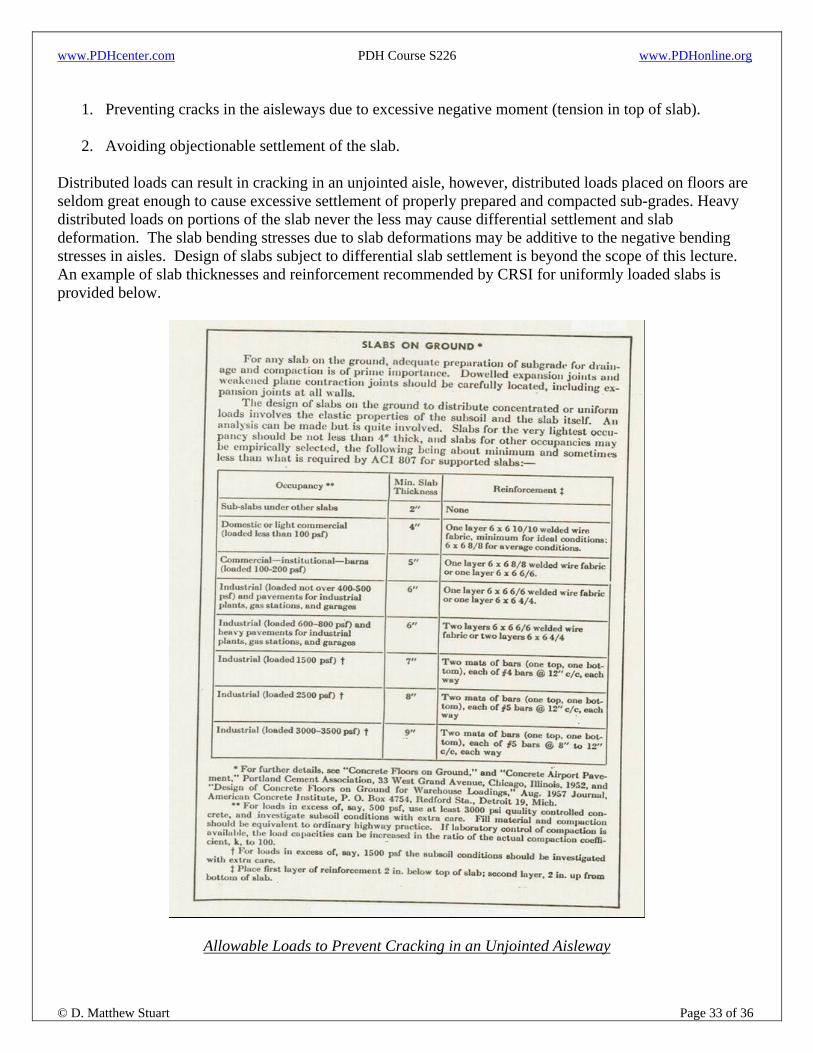
1. Preventing cracks in the aisleways due to excessive negative moment (tension in top of slab).
2. Avoiding objectionable settlement of the slab.
Distributed loads can result in cracking in an unjointed aisle, however, distributed loads placed on floors are seldom great enough to cause excessive settlement of properly prepared and compacted sub-grades. Heavy distributed loads on portions of the slab never the less may cause differential settlement and slab deformation. The slab bending stresses due to slab deformations may be additive to the negative bending stresses in aisles. Design of slabs subject to differential slab settlement is beyond the scope of this lecture. An example of slab thicknesses and reinforcement recommended by CRSI for uniformly loaded slabs is provided below.
Allowable Loads to Prevent Cracking in an Unjointed Aisleway

www.PDHcenter.com PDH Course S226 www.PDHonline.org
© D. Matthew Stuart Page 34 of 36
In an unjointed aisleway between distributed load areas, the maximum negative bending moment in the slab may be up to twice as great as the bending moment of the slab beneath the loaded area. As a result, one design objective is to limit the maximum negative moment stresses in the aisleway so that cracking will not occur. The PCA publication on slab design that has been used as the basis for this lecture presents two methods to determine the magnitude of allowable distributed loads; one is based on the use of tables and the other involves figures. Only the use of the design tables is discussed in this lecture. The following notes apply to these same tables, therefore the referenced table numbers pertain to the PCA publication and not this lecture.
• Table 5-3b is used if the aisle and storage layout is variable and may be changed during the service life of the floor. If the layout is permanently fixed, Table 5-4b should is used.
• Shrinkage stresses may be disregarded in the design procedure.
• It should be noted that the k value of the sub-grade, rather than the k value on top of the sub-base (if
there is one), is used in Tables 5-3b and 5-4b. This is appropriate for distributed loads covering large areas, while the use of the k-value on the top of the sub-base is appropriate for concentrated loads.
• The allowable loads (for variable storage layouts) in Table 5-4b are based on a safety factor of 2.0
(i.e. the allowable working stress = one-half of the concrete flexural strength). The allowable working stress (ft) is computed by dividing the 28-day flexural strength (MOR, or MR) by the safety factor. The allowable load in PSF is then computed as; W = 0.123ft(hk)½; where h = the slab thickness.
• For fixed storage layouts, as discussed previously, the slab stresses under the disturbed loads vary
with the aisle width (s), the load width (r), the load magnitude, and the joint location. In a storage area where this layout is known and will remain fixed through out the service life of the floor, the heavier distributed loads shown in Table 5-4b are permissible.
Maximum Loads and Critical Aisle Width
For a given slab thickness and sub-grade strength there is a critical aisle width for which the slab stress in the aisleway are maximized. This means that both narrower and wider aisles will allow heavier loads to be placed on the slab. This critical aisle width exists when the maximum bending moment in the aisle due to a load on one side of the aisle coincides with the point of maximum moment from the load on the other side of the aisle. This condition effectively doubles the negative bending moment (tension in the top of slab) at the aisle centerline. For aisle widths other than the critical aisle width, the maximum bending moments due to loads on each side of the aisle do not coincide and the load on one side of the aisle may even counteract stresses caused by a load on the other side.
Allowable Loads to Prevent Slab Settlement In the previous discussion, the allowable loads were based on preventing a crack in an unjointed aisleway between loaded storage areas. If these cracks can be tolerated or if there are joints in the aisleways, a restriction on the load magnitude may not be necessary. In this case, the limit of load depends on the tolerable settlement of the slab.

www.PDHcenter.com PDH Course S226 www.PDHonline.org
© D. Matthew Stuart Page 35 of 36
Unusual Loads and Other Considerations Special load configurations; unusual wheel or post configurations, tracked vehicles, vehicles with closely spaced axles or with more than 4 wheels per axle, very large wheel contact areas, or strip loads, all differ substantially from those indicated in the previous discussions. These conditions may be analyzed by one of the following methods:
1. For concentrated loads (wheel or post loads), slab stresses, deflections, and soil pressures may be determined with influence charges or a computer program. The influence charts may also be used for strip loads if the length of the load contact area is not great.
2. When the dimensions of a load contact area are large (for example, distributed loads in a storage bay
or a strip load), the condition can be modeled as a one-dimensional problem and the method of Hetenyi or a finite element analysis computer program may be used.
Distributed Steel for Slabs on Grade
Distributed steel refers to welded wire fabric or reinforcing bars placed in concrete slabs for the purposes of controlling random cracking. The relatively small amount of steel is used to hold together fracture faces when random cracks form. When low shrinkage or shrinkage compensating concrete is used and floor joints are spaced less than 25 feet apart, distributed steel is not necessary because the risk of random cracking is minimal. In slabs with long joint spacings (i.e. spacing is greater than those recommended in Table 7 above) the purpose of distributed steel is to hold random intermediate cracks tightly closed.
Since critical flexural stresses occur in both the top and bottom of concrete floors, steel should be placed in two layers. While this may be ideal for resisting stress, double layers of steel are not always economically justified. More often, a single layer of steel is used to minimize cracking at the slab surface. Steel is most effective when positioned at 1/3 the depth of the slab from the top and a minimum of 1½ inches from the surface. Distributed steel in sufficient quantity can minimize the number of joints required in floor slabs. Distributed steel does not however, prevent cracking, compensate for poor sub-grade preparation, or significantly increase the load carrying capacity of the floor. Distributed steel reinforcement (both wire mesh or bar mats), should be terminated within 2 inches of both sides of contraction and construction joints. Failure to cut all of the wires or bars may restrain joint widening, and depending on the remaining concrete shrinkage potential, result in intermediate random cracks.
Determining Amount of Distributed Steel
Although no longer recommended by ACI Committee 360 (because it may result in a percentage of steel unable to restrain crack widening sufficient enough to promote adequate load-transfer in heavy-duty industrial slabs), the Sub-Grade Drag Formula (SGDF) has been used for some time to determine the amount of distributed slab steel. This formula is provided below:

www.PDHcenter.com PDH Course S226 www.PDHonline.org
© D. Matthew Stuart Page 36 of 36
The SGDF often results in calculated steel areas less than 0.1% of the cross sectional area of the slab. However, based on experience and slab performance surveys, researchers, floor designers, and contractors suggest that for best performance, a minimum amount of distributed steel equal to 0.1% of the Ag of the slab is recommended. In addition, reinforcement ratios higher than those calculated by the traditional SGDF provide an additional safety factor against crack widening.
Alternative Methods for Determining the Amount of Distributed Steel Researchers at the University of Texas have proposed a modified sub-grade drag formula for determining the required amount of distributed steel. Based on experimental results from studies of sub-base friction, the following formula was developed, which better represents the actual frictional resistance of a range of available sub-base types:


![Concrete One-way Slabs - Timber design...Concrete One-way Slabs By using the [Concrete Member] design module linked to the [Analysis] design module, one-way slabs can be designed](https://img.dokumen.tips/doc/110x75/6128234cdce56b427c583dcd/concrete-one-way-slabs-timber-design-concrete-one-way-slabs-by-using-the-concrete.jpg)


![Analysis & Design of Steel Deck – Concrete Composite Slabs [Budi Ryanto Widjaja]](https://img.dokumen.tips/doc/110x75/5533acc34a7959de518b4a1e/analysis-design-of-steel-deck-concrete-composite-slabs-budi-ryanto-widjaja.jpg)