Embed Size (px)
Citation preview
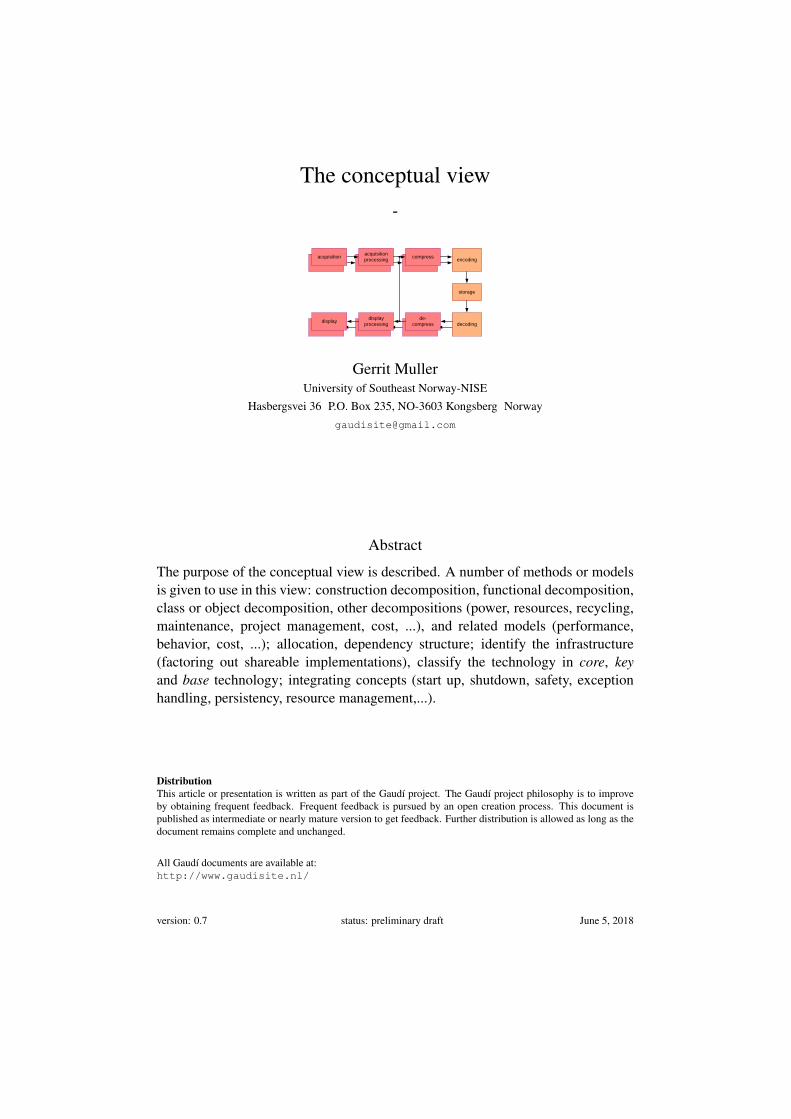
The conceptual view-
storage
acquisition
processingcompress
encoding
display
processing
de-
compress decodingdisplay
acquisition
Gerrit MullerUniversity of Southeast Norway-NISE
Hasbergsvei 36 P.O. Box 235, NO-3603 Kongsberg Norway
Abstract
The purpose of the conceptual view is described. A number of methods or modelsis given to use in this view: construction decomposition, functional decomposition,class or object decomposition, other decompositions (power, resources, recycling,maintenance, project management, cost, ...), and related models (performance,behavior, cost, ...); allocation, dependency structure; identify the infrastructure(factoring out shareable implementations), classify the technology in core, keyand base technology; integrating concepts (start up, shutdown, safety, exceptionhandling, persistency, resource management,...).
DistributionThis article or presentation is written as part of the Gaudí project. The Gaudí project philosophy is to improveby obtaining frequent feedback. Frequent feedback is pursued by an open creation process. This document ispublished as intermediate or nearly mature version to get feedback. Further distribution is allowed as long as thedocument remains complete and unchanged.
All Gaudí documents are available at:http://www.gaudisite.nl/
version: 0.7 status: preliminary draft June 5, 2018
1 Introduction
The conceptual view is used to understand how the product is achieving the speci-fication. The methods and models used in the conceptual view should discuss thehow of the product in conceptual terms. The lifetime of the concepts is longer thanthe specific implementation described in the Realization view. The conceptual viewis more stable and reusable than the realization view.
The dominant principle in design is decomposition, often immediately coupledto interface management of the interfaces of the resulting components. It is importantto realize that any system can be decomposed in many relevant ways. The mostcommon ones are discussed here briefly: construction decomposition, section 2,functional decomposition, section 3, class or object decomposition, other decom-positions (power, resources, recycling, maintenance, project management, cost,execution architecture...), and related models (performance, behavior, cost, ...).
If multiple decompositions are used then the relationships between decompo-sitions are important. One of the methods to work with these relationships is viaallocation. Within a decomposition and between decompositions the dependencystructure is important.
From development management point of view it is useful to identify the infras-tructure (factoring out shareable implementations), and to classify the technologyin core, key and base technology.
The complement of decomposition is integration. Articulating the integratingconcepts (start up, shutdown, safety, exception handling, persistency, resourcemanagement,...) provides guidance to the developers and helps to get a consis-tently behaving system.
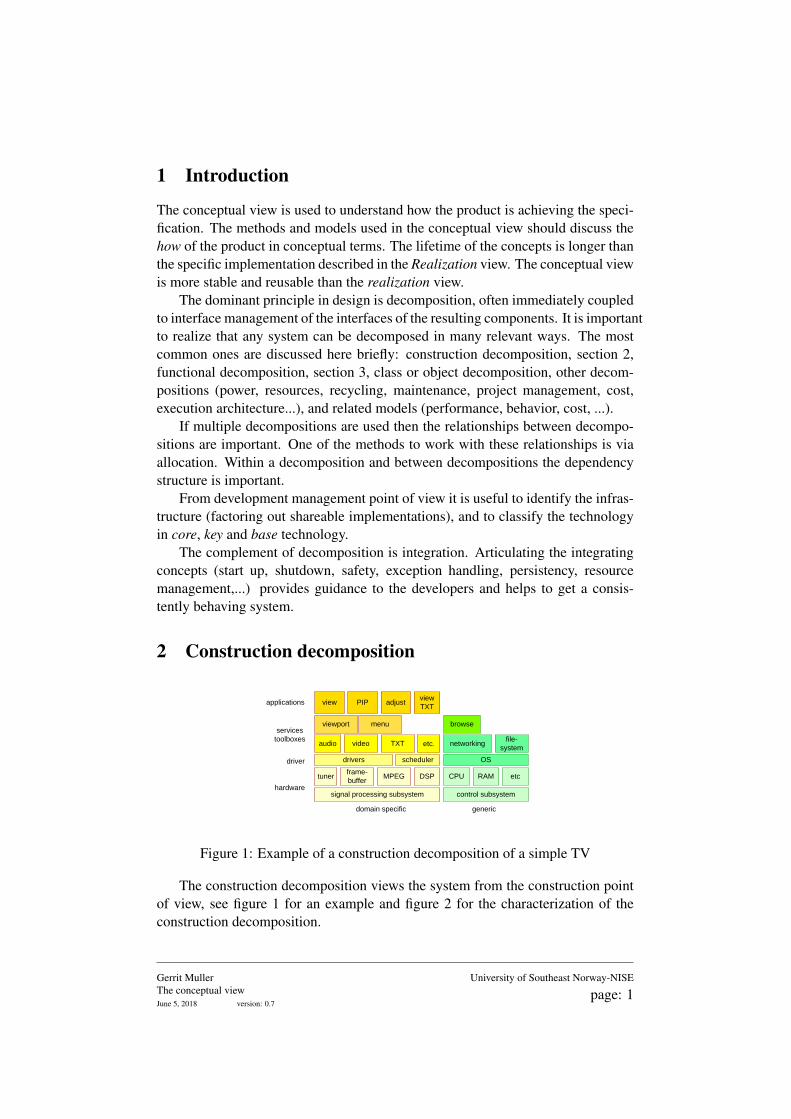
2 Construction decomposition
tunerframe-
bufferMPEG DSP CPU RAM
drivers scheduler OS
etc
audio video TXTfile-
systemnetworkingetc.
view PIP
browseviewport menu
adjustview
TXT
hardware
driver
applications
services
toolboxes
domain specific generic
signal processing subsystem control subsystem
Figure 1: Example of a construction decomposition of a simple TV
The construction decomposition views the system from the construction pointof view, see figure 1 for an example and figure 2 for the characterization of theconstruction decomposition.
Gerrit MullerThe conceptual viewJune 5, 2018 version: 0.7
University of Southeast Norway-NISE
page: 1
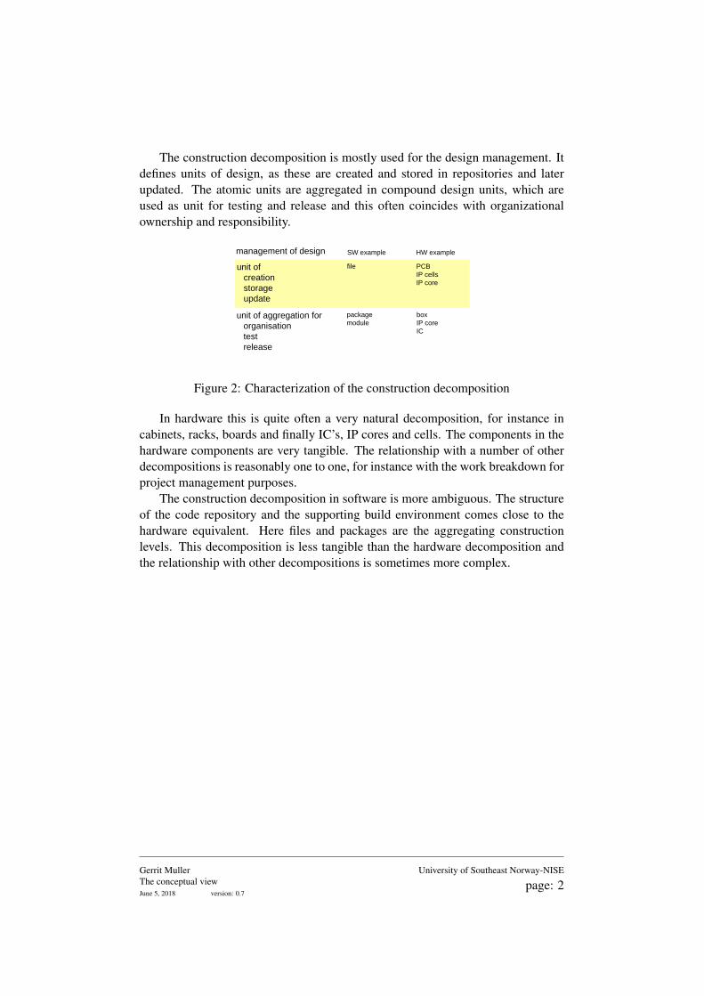
The construction decomposition is mostly used for the design management. Itdefines units of design, as these are created and stored in repositories and laterupdated. The atomic units are aggregated in compound design units, which areused as unit for testing and release and this often coincides with organizationalownership and responsibility.
management of design
file
box
IP core
IC
unit of aggregation for
organisation
test
release
unit of
creation
storage
update
SW example
package
module
PCB
IP cells
IP core
HW example
Figure 2: Characterization of the construction decomposition
In hardware this is quite often a very natural decomposition, for instance incabinets, racks, boards and finally IC’s, IP cores and cells. The components in thehardware components are very tangible. The relationship with a number of otherdecompositions is reasonably one to one, for instance with the work breakdown forproject management purposes.
The construction decomposition in software is more ambiguous. The structureof the code repository and the supporting build environment comes close to thehardware equivalent. Here files and packages are the aggregating constructionlevels. This decomposition is less tangible than the hardware decomposition andthe relationship with other decompositions is sometimes more complex.
Gerrit MullerThe conceptual viewJune 5, 2018 version: 0.7
University of Southeast Norway-NISE
page: 2
3 Functional decomposition
The functions as described in the functional view have to be performed by thedesign. These functions often are an aggregation of more elementary functions inthe design. The functional decomposition decomposes end user functions in moreelementary functions.
Be aware of the fact that the word function in system design is heavily overloaded.It does not help to define sharp boundaries with respect to the functional decom-position. Main criterium for a good functional decomposition is its useability fordesign. A functional decomposition provides insight how the system will accom-plish its job.
storage
acquisition
processingcompress
encoding
display
processing
de-
compress decodingdisplay
acquisition
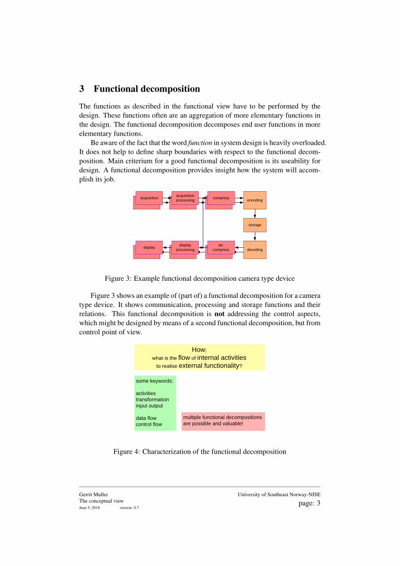
Figure 3: Example functional decomposition camera type device
Figure 3 shows an example of (part of) a functional decomposition for a cameratype device. It shows communication, processing and storage functions and theirrelations. This functional decomposition is not addressing the control aspects,which might be designed by means of a second functional decomposition, but fromcontrol point of view.
How;
what is the flow of internal activities
to realise external functionality?
some keywords:
activities
transformation
input output
data flow
control flow
multiple functional decompositions
are possible and valuable!
Figure 4: Characterization of the functional decomposition
Gerrit MullerThe conceptual viewJune 5, 2018 version: 0.7
University of Southeast Norway-NISE
page: 3
4 Designing with multiple decompositions
The design of complex systems always requires multiple decompositions, for instancea construction and a functional decomposition. Many designers in the design teamneed support to cope with this multiplicity.
Most designers don’t anticipate cross system design issues, for instance whenasked in preparation of design team meetings. This limited anticipation is causedby the locality of the viewpoint, implicitly chosen by the designers.
memory usage
export
server
server
database
server
SNR
accuracy
latency
processing
brightness
next
play movie
render film
query DB What is the memory usage of
the user interface
when querying the DB
import
server
user
interface
functions
component
characteristics
when performing <function>?
of the <component>
How about the <characteristic>
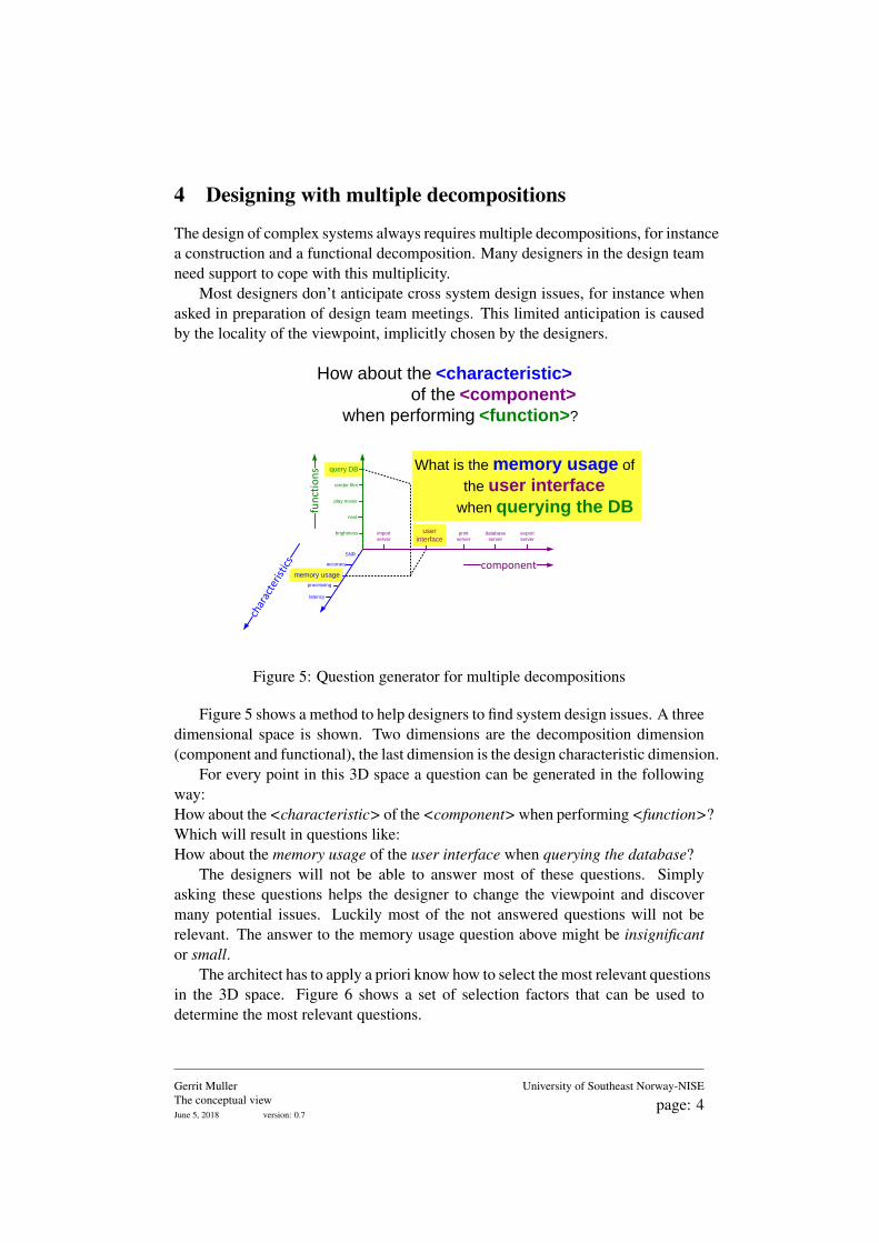
Figure 5: Question generator for multiple decompositions
Figure 5 shows a method to help designers to find system design issues. A threedimensional space is shown. Two dimensions are the decomposition dimension(component and functional), the last dimension is the design characteristic dimension.
For every point in this 3D space a question can be generated in the followingway:How about the <characteristic> of the <component> when performing <function>?Which will result in questions like:How about the memory usage of the user interface when querying the database?
The designers will not be able to answer most of these questions. Simplyasking these questions helps the designer to change the viewpoint and discovermany potential issues. Luckily most of the not answered questions will not berelevant. The answer to the memory usage question above might be insignificantor small.
The architect has to apply a priori know how to select the most relevant questionsin the 3D space. Figure 6 shows a set of selection factors that can be used todetermine the most relevant questions.
Gerrit MullerThe conceptual viewJune 5, 2018 version: 0.7
University of Southeast Norway-NISE
page: 4
Critical for system performance
Risk planning wise
Least robust part of the design
Suspect part of the design
- experience based
- person based
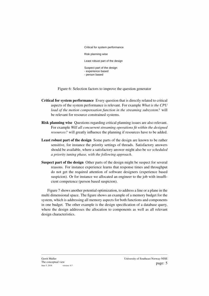
Figure 6: Selection factors to improve the question generator
Critical for system performance Every question that is directly related to criticalaspects of the system performance is relevant. For example What is the CPUload of the motion compensation function in the streaming subsystem? willbe relevant for resource constrained systems.
Risk planning wise Questions regarding critical planning issues are also relevant.For example Will all concurrent streaming operations fit within the designedresources? will greatly influence the planning if resources have to be added.
Least robust part of the design Some parts of the design are known to be rathersensitive, for instance the priority settings of threads. Satisfactory answersshould be available, where a satisfactory answer might also be we scheduleda priority tuning phase, with the following approach.
Suspect part of the design Other parts of the design might be suspect for severalreasons. For instance experience learns that response times and throughputdo not get the required attention of software designers (experience basedsuspicion). Or for instance we allocated an engineer to the job with insuffi-cient competence (person based suspicion).
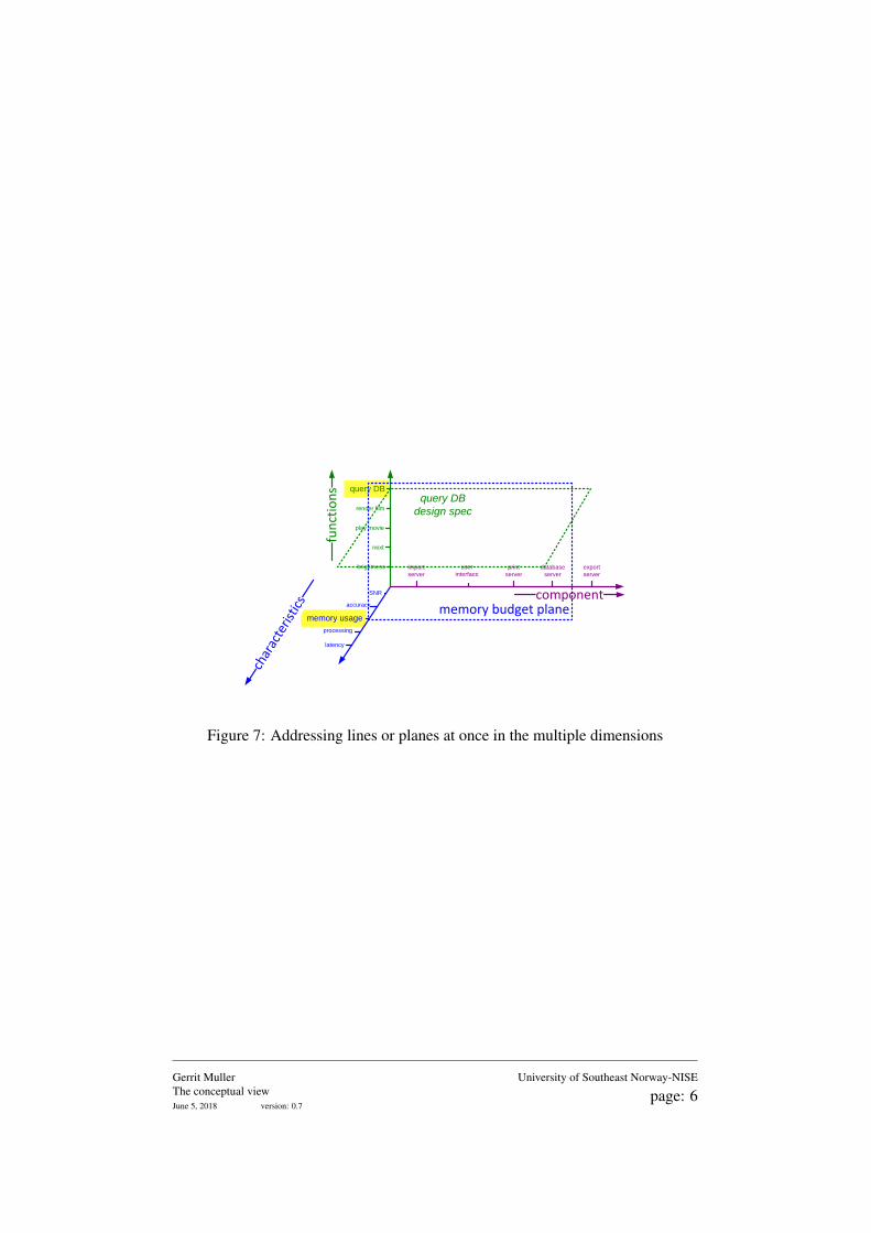
Figure 7 shows another potential optimization, to address a line or a plane in themulti dimensional space. The figure shows an example of a memory budget for thesystem, which is addressing all memory aspects for both functions and componentsin one budget. The other example is the design specification of a database query,where the design addresses the allocation to components as well as all relevantdesign characteristics.
Gerrit MullerThe conceptual viewJune 5, 2018 version: 0.7
University of Southeast Norway-NISE
page: 5
component
memory usage
export
server
server
database
server
SNR
accuracy
latency
processing
brightness
next
play movie
render film
query DB
memory budget plane
import
server
user
interface
fun
ctio
ns
char
acte
ristic
s
query DB
design spec
Figure 7: Addressing lines or planes at once in the multiple dimensions
Gerrit MullerThe conceptual viewJune 5, 2018 version: 0.7
University of Southeast Norway-NISE
page: 6
5 Internal Information Model
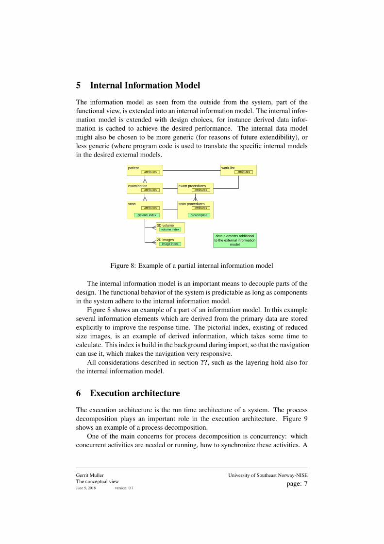
The information model as seen from the outside from the system, part of thefunctional view, is extended into an internal information model. The internal infor-mation model is extended with design choices, for instance derived data infor-mation is cached to achieve the desired performance. The internal data modelmight also be chosen to be more generic (for reasons of future extendibility), orless generic (where program code is used to translate the specific internal modelsin the desired external models.
patient
examination
scan
2D images
3D volume
attributes
scan procedures
exam procedures
attributes
attributes
attributes
attributes
work-listattributes
volume index
image index
pictorial index precompiled
data elements additional
to the external information
model
Figure 8: Example of a partial internal information model
The internal information model is an important means to decouple parts of thedesign. The functional behavior of the system is predictable as long as componentsin the system adhere to the internal information model.
Figure 8 shows an example of a part of an information model. In this exampleseveral information elements which are derived from the primary data are storedexplicitly to improve the response time. The pictorial index, existing of reducedsize images, is an example of derived information, which takes some time tocalculate. This index is build in the background during import, so that the navigationcan use it, which makes the navigation very responsive.
All considerations described in section ??, such as the layering hold also forthe internal information model.
6 Execution architecture
The execution architecture is the run time architecture of a system. The processdecomposition plays an important role in the execution architecture. Figure 9shows an example of a process decomposition.
One of the main concerns for process decomposition is concurrency: whichconcurrent activities are needed or running, how to synchronize these activities. A
Gerrit MullerThe conceptual viewJune 5, 2018 version: 0.7
University of Southeast Norway-NISE
page: 7
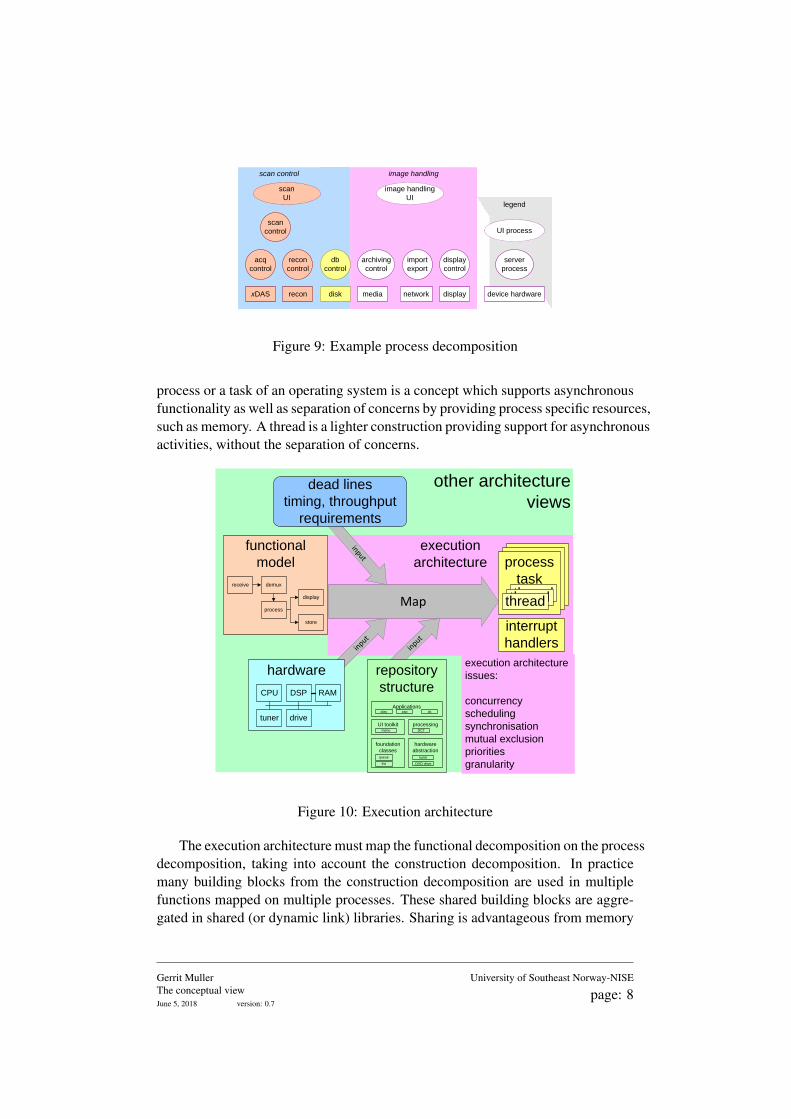
image handlingscan control
scan
control
acq
control
recon
control
xDAS recon
db
control
disk
scan
UI
image handling
UI
archiving
control
media
import
export
network
display
control
display device hardware
server
process
UI process
legend
Figure 9: Example process decomposition
process or a task of an operating system is a concept which supports asynchronousfunctionality as well as separation of concerns by providing process specific resources,such as memory. A thread is a lighter construction providing support for asynchronousactivities, without the separation of concerns.
other architecture
views
execution
architecture
functional
model
process
display
receive demux
store
Map
process
task
threadthreadthread
process
task
threadthreadthread
process
taskthreadthreadthread
interrupt
handlersinput
hardware
tuner drive
CPU DSP RAM
input
repository
structure
queue
DCTmenu
txt
tuner
foundation
classes
hardware
abstraction
list DVD drive
UI toolkit processing
Applicationsplay zap
input
dead lines
timing, throughput
requirements
execution architecture
issues:
concurrency
scheduling
synchronisation
mutual exclusion
priorities
granularity
Figure 10: Execution architecture
The execution architecture must map the functional decomposition on the processdecomposition, taking into account the construction decomposition. In practicemany building blocks from the construction decomposition are used in multiplefunctions mapped on multiple processes. These shared building blocks are aggre-gated in shared (or dynamic link) libraries. Sharing is advantageous from memory
Gerrit MullerThe conceptual viewJune 5, 2018 version: 0.7
University of Southeast Norway-NISE
page: 8

consumption point of view, some attention is required for the configuration managementside1.
Figure 10 shows the role of the execution architecture. The main inputs are thereal time and performance requirements at the one hand and the hardware designat the other hand. The functions need to be mapped on processes, threads andinterrupt handlers, synchronization method and granularity need to be defined andthe scheduling behavior (for instance priority based, which requires priorities to bedefined).
1The dll-hell is not an windows-only problem. Multiple pieces of software sharing the samelibrary can easily lead to version problems, module 1 requires version 1.13, while module 2 requiresversion 2.11. Despite all compatibility claims it often does not work.
Gerrit MullerThe conceptual viewJune 5, 2018 version: 0.7
University of Southeast Norway-NISE
page: 9
7 Performance
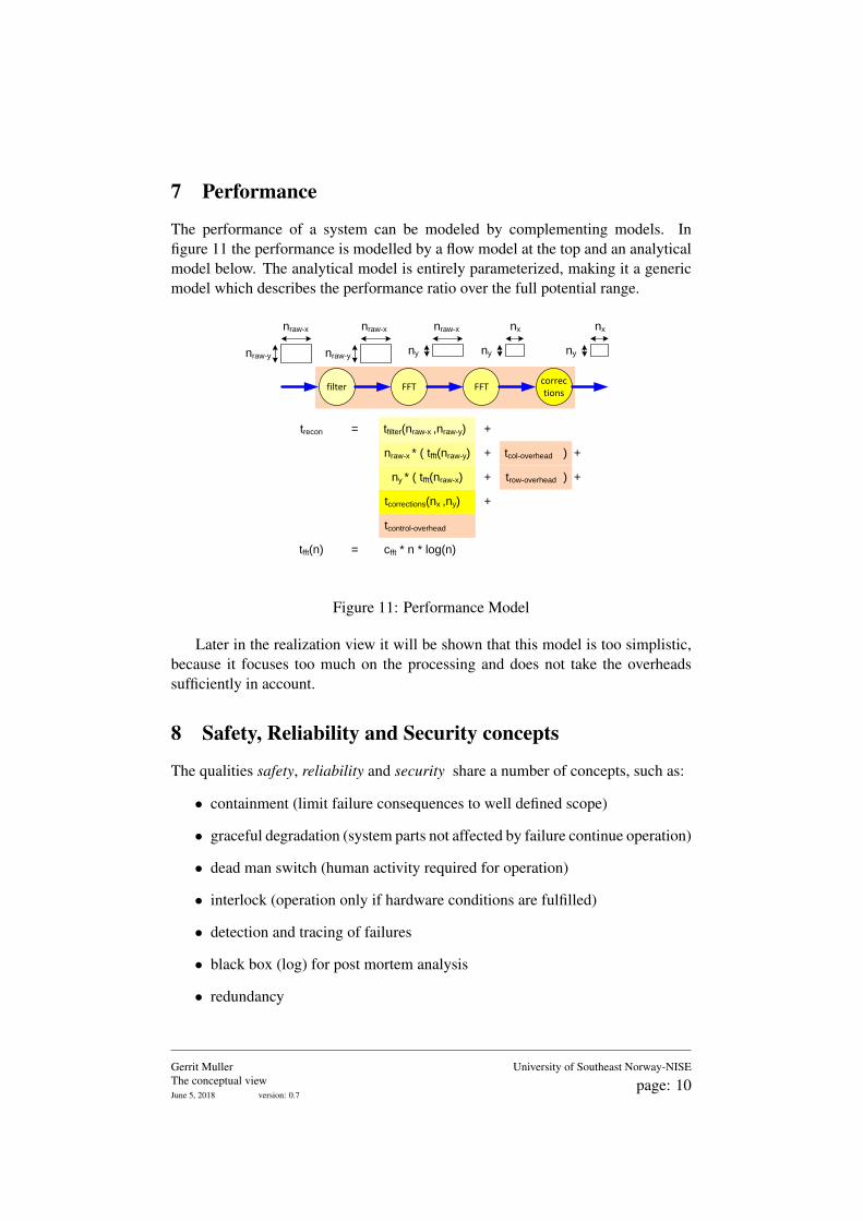
The performance of a system can be modeled by complementing models. Infigure 11 the performance is modelled by a flow model at the top and an analyticalmodel below. The analytical model is entirely parameterized, making it a genericmodel which describes the performance ratio over the full potential range.
trecon =
nraw-x * ( tfft(nraw-y)
ny * ( tfft(nraw-x)
tfilter(nraw-x ,nraw-y) +
+
+
tfft(n) = cfft * n * log(n)
filter FFT FFTcorrections
nraw-x
nraw-y
nraw-x
nraw-y
nraw-x
ny
nx
ny
nx
ny
tcol-overhead
tcorrections(nx ,ny)
trow-overhead
tcontrol-overhead
+
) +
) +
Figure 11: Performance Model
Later in the realization view it will be shown that this model is too simplistic,because it focuses too much on the processing and does not take the overheadssufficiently in account.
8 Safety, Reliability and Security concepts
The qualities safety, reliability and security share a number of concepts, such as:
• containment (limit failure consequences to well defined scope)
• graceful degradation (system parts not affected by failure continue operation)
• dead man switch (human activity required for operation)
• interlock (operation only if hardware conditions are fulfilled)
• detection and tracing of failures
• black box (log) for post mortem analysis
• redundancy
Gerrit MullerThe conceptual viewJune 5, 2018 version: 0.7
University of Southeast Norway-NISE
page: 10

A common guideline in applying any of these concepts is that the more criticala function is, the higher the understandability should be, or in other words thesimpler the applied concepts should be. Many elementary safety functions areimplemented in hardware, avoiding large stacks of complex software.
Gerrit MullerThe conceptual viewJune 5, 2018 version: 0.7
University of Southeast Norway-NISE
page: 11
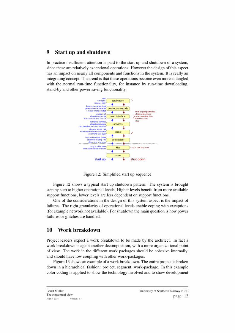
9 Start up and shutdown
In practice insufficient attention is paid to the start up and shutdown of a system,since these are relatively exceptional operations. However the design of this aspecthas an impact on nearly all components and functions in the system. It is really anintegrating concept. The trend is that these operations become even more entangledwith the normal run-time functionality, for instance by run-time downloading,stand-by and other power saving functionality.
discover kernel HW
initialise kernel data structures
determine next layer
load and initialise loader
determine loading HW
determine next layer
bring in initial state
load and initialise firmware
configure services
allocate resources
load, initialise and start services
configure UI
allocate resources
load, initialise and start UI
detect external services
publish internal services
connect where needed
load
configure
initialise, start
power
boot-loader
HW
kernel
services
user interface
connect to outside
application
stop in safe sequence
flush ongoing activities
close connections
save persistent data
free resources
stop
start up
HW SW interface
shut down
Figure 12: Simplified start up sequence
Figure 12 shows a typical start up shutdown pattern. The system is broughtstep by step to higher operational levels. Higher levels benefit from more availablesupport functions, lower levels are less dependent on support functions.
One of the considerations in the design of this system aspect is the impact offailures. The right granularity of operational levels enable coping with exceptions(for example network not available). For shutdown the main question is how powerfailures or glitches are handled.
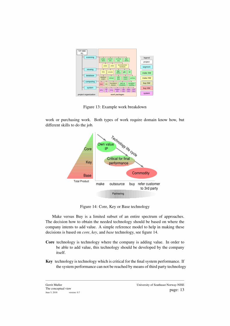
10 Work breakdown
Project leaders expect a work breakdown to be made by the architect. In fact awork breakdown is again another decomposition, with a more organizational pointof view. The work in the different work packages should be cohesive internally,and should have low coupling with other work-packages.
Figure 13 shows an example of a work breakdown. The entire project is brokendown in a hierarchical fashion: project, segment, work-package. In this examplecolor coding is applied to show the technology involved and to show development
Gerrit MullerThe conceptual viewJune 5, 2018 version: 0.7
University of Southeast Norway-NISE
page: 12
work packagesproject organization
TIP:NBE
R1
xDASreconstruction
hardware
viewing
database
scanning
xFEC
run time
acq
prepa-
ration
conver-
sion
algo-
rithms
UIgfxalgo-
rithmsVDU console
import
exportarchive
bulk
dataclinical
database
engine
computing
system
host OSfoundation
classes
start up
shutdown
exception
handling
integra-
tionSPS
SD
STPS
alfa
test
beta
test
conf
man
make SW
make HW
buy SW
buy HW
system
segment
project
legend
Figure 13: Example work breakdown
work or purchasing work. Both types of work require domain know how, butdifferent skills to do the job.
Core
Key
Base
make outsource buy refer customer to 3rd party
Own value IP
Critical for final performance
Commodity
Technology life cycle
Partnering
Total Product
Figure 14: Core, Key or Base technology
Make versus Buy is a limited subset of an entire spectrum of approaches.The decision how to obtain the needed technology should be based on where thecompany intents to add value. A simple reference model to help in making thesedecisions is based on core, key, and base technology, see figure 14.
Core technology is technology where the company is adding value. In order tobe able to add value, this technology should be developed by the companyitself.
Key technology is technology which is critical for the final system performance. Ifthe system performance can not be reached by means of third party technology
Gerrit MullerThe conceptual viewJune 5, 2018 version: 0.7
University of Southeast Norway-NISE
page: 13
than the company must develop it themselves. Otherwise outsourcing orbuying is attractive, in order to focus as much as possible on core technologyadded value. However when outsourcing or buying an intimate partnershipis recommended to ensure the proper performance level.
Base technology is technology which is available on the market and where thedevelopment is driven by other systems or applications. Care should be takenthat these external developments can be followed. Own developments hereare de-focusing the attention from the company’s core technology.
existing base system
new HW subsystem
SW dev system
test HW subsystem
test SW for new HW subsystem
new application
existing base system
integrate subsystem
SW dev system test and refine application
integrate and refineapplication
adopt existing base SW
new base system test new base systemintegrate HW
system
integrate
system
SW for new HW subsystem
adopt existing base SW
existing new
2 partial
systems for
SW testing
2 existing
base
systems
new base
systems
time
integrated
system
application integration
new subsystem
integration
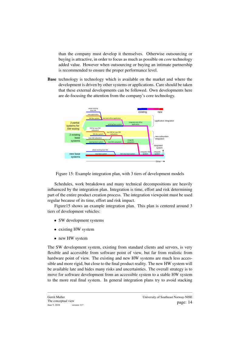
Figure 15: Example integration plan, with 3 tiers of development models
Schedules, work breakdown and many technical decompositions are heavilyinfluenced by the integration plan. Integration is time, effort and risk determiningpart of the entire product creation process. The integration viewpoint must be usedregular because of its time, effort and risk impact.
Figure15 shows an example integration plan. This plan is centered around 3tiers of development vehicles:
• SW development systems
• existing HW system
• new HW system
The SW development system, existing from standard clients and servers, is veryflexible and accessible from software point of view, but far from realistic fromhardware point of view. The existing and new HW systems are much less acces-sible and more rigid, but close to the final product reality. The new HW system willbe available late and hides many risks and uncertainties. The overall strategy is tomove for software development from an accessible system to a stable HW systemto the more real final system. In general integration plans try to avoid stacking
Gerrit MullerThe conceptual viewJune 5, 2018 version: 0.7
University of Southeast Norway-NISE
page: 14

too many uncertainties by looking for ways to test new modules in a stable knownenvironment, before confronting new modules with each other.
Gerrit MullerThe conceptual viewJune 5, 2018 version: 0.7
University of Southeast Norway-NISE
page: 15

11 Acknowledgements
Constructive remarks from Peter Bingley, Peter van den Hamer, Ton Kostelijk,William van der Sterren and Berry van der Wijst have been integrated in thisdocument.
References
[1] Gerrit Muller. The system architecture homepage. http://www.gaudisite.nl/index.html, 1999.
HistoryVersion: 0.7, date: September 18, 2003 changed by: Gerrit Muller
• corrected copy/paste artefact in ”Introduction”Version: 0.6, date: September 9, 2003 changed by: Gerrit Muller
• updated text of Section ”Start up and shutdown” about the frequency of occuranceVersion: 0.5, date: May 6, 2003 changed by: Gerrit Muller
• added text to section ”internal information model”• added text to section ”Start up and shutdown”• changed status to preliminary draft
Version: 0.4, date: October 3, 2002 changed by: Gerrit Muller• added integration plan including descriptive text
Version: 0.3, date: October 1, 2002 changed by: Gerrit Muller• added text to construction decomposition• added figure construction decomposition characterization• added figure functional decomposition characterization• added information model• section acknowledgements added
Version: 0.2, date: September 3, 2002 changed by: Gerrit Muller• added section Safety, reliability and security concepts• added simplified start up diagram• added work breakdown and text• added core key base diagram and text• added performance model• added execution architecture diagram and text• added example process decomposition
Version: 0.1, date: July 9 2002 changed by: Gerrit Muller• updated figure Functional decomposition
Version: 0, date: April 2. 2002 changed by: Gerrit Muller• Created, no changelog yet
Gerrit MullerThe conceptual viewJune 5, 2018 version: 0.7
University of Southeast Norway-NISE
page: 16