Embed Size (px)
Citation preview
i
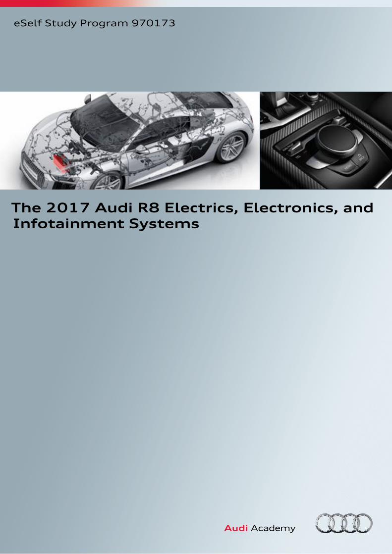
The 2017 Audi R8 Electrics, Electronics, and Infotainment Systems
eSelf Study Program 970173
ii
This eSSP contains video links which you
can use to access interactive media.
Audi of America, LLC Service Training Created in the U.S.A. Created 1/2016 Course Number 970173©2016 Audi of America, LLC
All rights reserved. Information contained in this manual is based on the latest information available at the time of printing and is subject to the copyright and other intellectual property rights of Audi of America, LLC., its affiliated companies and its licensors. All rights are reserved to make changes at any time without notice. No part of this document may be reproduced, stored in a retrieval system, or transmitted in any form or by any means, electronic, mechanical, photocopying, recording or otherwise, nor may these materials be modified or reposted to other sites without the prior expressed written permission of the publisher.All requests for permission to copy and redistribute information should be referred to Audi of America, LLC.
Always check Technical Bulletins and the latest electronic service repair literature for information that may supersede any information included in this booklet.
Revision 1:1/2016

iii
This eSelf Study Program teaches a basic knowledge of the design and functions of new models, new automotive components or technologies. It is not a Repair Manual! All values given are intended as a guideline only. For maintenance and repair work, always refer to the current technical literature.
Note
Reference
Electrical system ................................................................................ 1
Introduction ...............................................................................................................................................................1
Control module profiles ............................................................................................................................................9
Exterior lights ......................................................................................................................................................... 27
Audi drive select ...................................................................................................................................................... 31
Multifunction steering wheel ................................................................................................................................. 33
Infotainment ....................................................................................35
Sound systems ........................................................................................................................................................ 36
Safety belt microphone .......................................................................................................................................... 38
Antenna overview ................................................................................................................................................... 39
Climate control .................................................................................41
Introduction ............................................................................................................................................................ 41
Passenger compartment ventilation .................................................................................................................... 42
Refrigerant circuit ................................................................................................................................................... 43
Service ..............................................................................................44
Inspection and maintenance ................................................................................................................................. 44
Self-study programs .........................................................................45
Knowledge assessment ....................................................................46
1
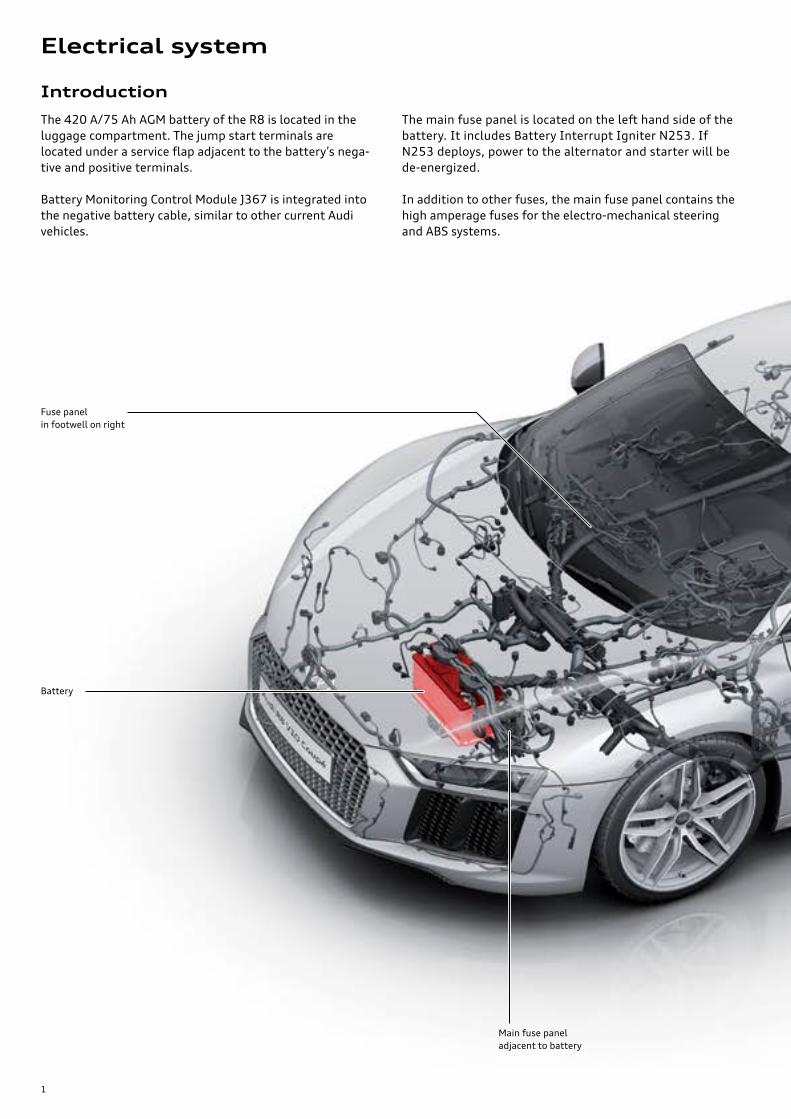
The 420 A/75 Ah AGM battery of the R8 is located in the luggage compartment. The jump start terminals are located under a service flap adjacent to the battery’s nega-tive and positive terminals.
Battery Monitoring Control Module J367 is integrated into the negative battery cable, similar to other current Audi vehicles.
The main fuse panel is located on the left hand side of the battery. It includes Battery Interrupt Igniter N253. If N253 deploys, power to the alternator and starter will be de-energized.
In addition to other fuses, the main fuse panel contains the high amperage fuses for the electro-mechanical steering and ABS systems.
Fuse panel in footwell on right
Battery
Main fuse panel adjacent to battery
Introduction
Electrical system

2
Fuse and relay panel below parcel shelf
Fuse and relay panel in E-box on right
Fuse and relay panel in E-box on left
641_128

3
J386
J387
J519
J587
J849
E87J844
G85
J527J285 J764
J792
J745
J104
J500
J533A32
J492
A28
J136
J234
J521
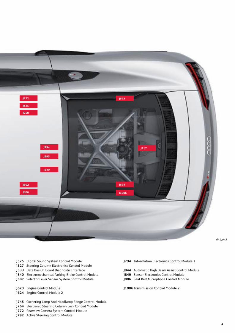
Installation locations of control modules
Key:
A28 Right Led Headlamp Power Output Module 2A32 Left Led Headlamp Power Output Module 2
E87 Front A/C Display Control Head
G85 Steering Angle Sensor
J104 ABS Control ModuleJ136 Memory Seat/Steering Column Adjustment Control Module
J217 Transmission Control ModuleJ234 Airbag Control Module
J250 Electronic Damping Control ModuleJ285 Instrument Cluster Control Module
J386 Driver Door Control ModuleJ387 Front Passenger Door Control ModuleJ393 Comfort System Central Control Module
J492 All Wheel Drive Control Module
J500 Power Steering Control ModuleJ502 Tire Pressure Monitoring Control ModuleJ519 Vehicle Electrical System Control Module 1J521 Front Passenger Memory Seat Control Module
Descriptions for the precise locations of the control modules and instructions for installation and removal can be found in ElsaPro. Some of the control modules shown in this overview are optional equipment and may not be installed in the vehicle.
4
J772
J525
J250
J886
J502
J217
J623
J624
J1006
J794
J393
J540
J136
J234
J521
641_043
J525 Digital Sound System Control ModuleJ527 Steering Column Electronics Control ModuleJ533 Data Bus On Board Diagnostic InterfaceJ540 Electromechanical Parking Brake Control ModuleJ587 Selector Lever Sensor System Control Module
J623 Engine Control ModuleJ624 Engine Control Module 2
J745 Cornering Lamp And Headlamp Range Control ModuleJ764 Electronic Steering Column Lock Control ModuleJ772 Rearview Camera System Control ModuleJ792 Active Steering Control Module
J794 Information Electronics Control Module 1
J844 Automatic High Beam Assist Control ModuleJ849 Sensor Electronics Control ModuleJ886 Seat Belt Microphone Control Module
J1006 Transmission Control Module 2
5
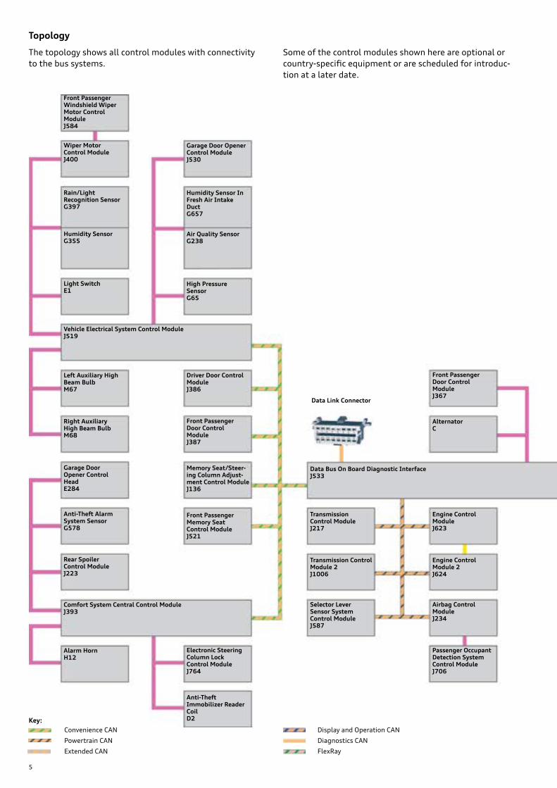
Topology
Powertrain CAN
Convenience CAN Display and Operation CAN
Diagnostics CAN
Extended CAN FlexRay
Key:
The topology shows all control modules with connectivity to the bus systems.
Some of the control modules shown here are optional or country-specific equipment or are scheduled for introduc-tion at a later date.
Driver Door Control ModuleJ386
Electronic Steering Column Lock Control ModuleJ764
Anti-Theft Alarm System SensorG578
Front Passenger Door Control ModuleJ387
Vehicle Electrical System Control ModuleJ519
Rain/Light Recognition SensorG397
Humidity SensorG355
Alarm HornH12
Wiper Motor Control ModuleJ400
Air Quality SensorG238
Humidity Sensor In Fresh Air Intake DuctG657
Data Link Connector
Data Bus On Board Diagnostic InterfaceJ533
Comfort System Central Control ModuleJ393
Memory Seat/Steer-ing Column Adjust-ment Control ModuleJ136
Front Passenger Memory Seat Control ModuleJ521
Light Switch E1
Garage Door Opener Control HeadE284
High Pressure SensorG65
Garage Door Opener Control Module J530
Engine Control ModuleJ623
Airbag Control ModuleJ234
Selector Lever Sensor System Control ModuleJ587
Passenger Occupant Detection System Control ModuleJ706
AlternatorC
Front Passenger Door Control ModuleJ367
Left Auxiliary High Beam Bulb M67
Right Auxiliary High Beam BulbM68
Rear Spoiler Control ModuleJ223
Engine Control Module 2J624
Transmission Control ModuleJ217
Transmission Control Module 2 J1006
Front Passenger Windshield Wiper Motor Control ModuleJ584
Anti-Theft Immobilizer Reader CoilD2
6
LIN bus
Sub-bus systems
MOST busChassis CAN bus
Modular Infotainment Platform (MIB) CAN
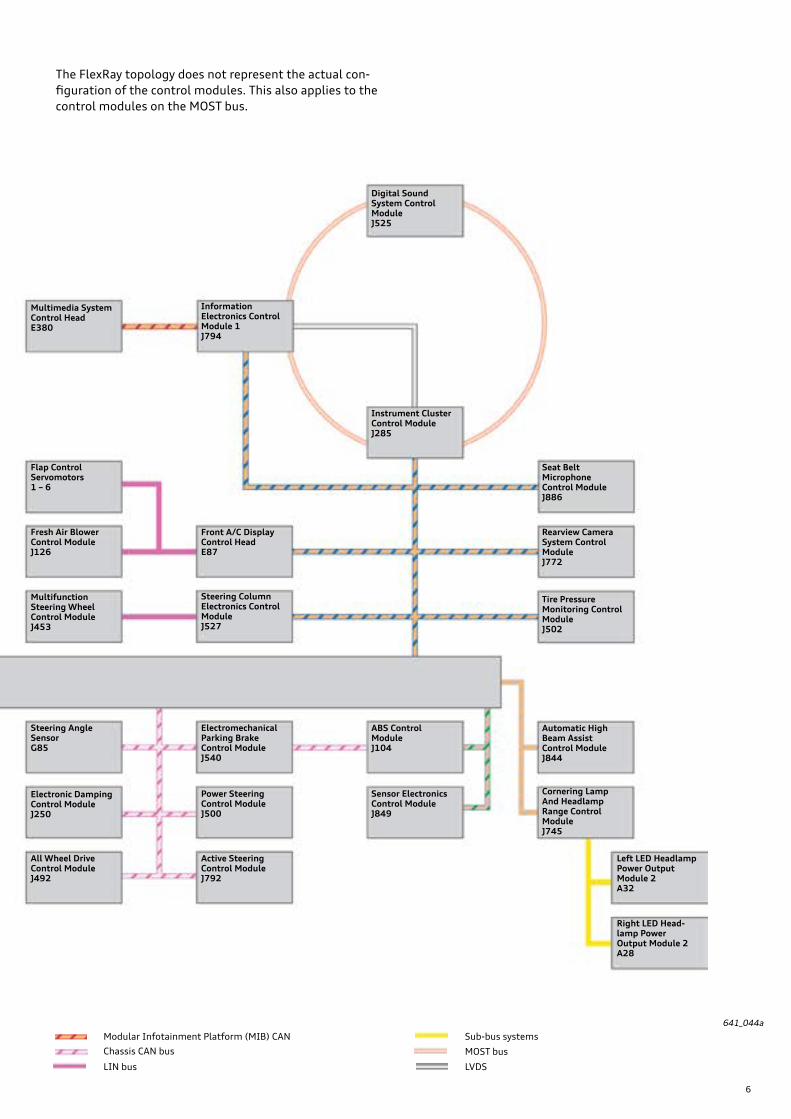
The FlexRay topology does not represent the actual con-figuration of the control modules. This also applies to the control modules on the MOST bus.
LVDS
Flap Control Servomotors1 – 6
Fresh Air Blower Control ModuleJ126
Steering Column Electronics Control ModuleJ527
Instrument Cluster Control ModuleJ285
Digital Sound System Control ModuleJ525
Information Electronics Control Module 1J794
Rearview Camera System Control ModuleJ772
Multimedia System Control HeadE380
Automatic High Beam Assist Control ModuleJ844
ABS Control ModuleJ104
641_044a
Tire Pressure Monitoring Control ModuleJ502
Power Steering Control ModuleJ500
Electromechanical Parking Brake Control ModuleJ540
Steering Angle SensorG85
Active Steering Control ModuleJ792
All Wheel Drive Control ModuleJ492
Electronic Damping Control ModuleJ250
Sensor Electronics Control ModuleJ849
Cornering Lamp And Headlamp Range Control Module J745
Left LED Headlamp Power Output Module 2 A32
Right LED Head-lamp Power Output Module 2 A28
Multifunction Steering Wheel Control ModuleJ453
Front A/C Display Control HeadE87
Seat Belt Microphone Control ModuleJ886

7
Bus system Cable color
Configuration Max. data transfer rate
Property
Powertrain CAN Electrical two-core bus system 500 kbit/s not single wire capable
Convenience CAN Electrical two-core bus system 500 kbit/s not single wire capable
Chassis CAN bus Electrical two-core bus system 500 kbit/s not single wire capable
Extended CAN Electrical two-core bus system 500 kbit/s not single wire capable
Display and Operation CAN Electrical two-core bus system 500 kbit/s not single wire capable
Modular Infotainment Platform (MIB) CAN
Electrical two-core bus system 500 kbit/s not single wire capable
Diagnostics CAN Electrical two-core bus system 500 kbit/s not single wire capable
FlexRay Electrical two-core bus system 10 Mbit/s not single wire capable
MOST bus (150) Fiber-optic bus system 150 Mbit/s Ring structure:an open circuit will result in total system failure
LIN bus Electrical single-core bus system 20 kbit/s Capable of single-core operation
Sub-bus system Electrical two-core bus system 500 kbit/s not single wire capable
LVDS Electrical two-core bus system approx. 200 Mbit/s not single wire capable
Overview of the bus systems
ReferenceFor further information about the FlexRay bus, refer to eSelf Study Program 970103, The 2011 Audi A8 Convenience Electronics and Networking Systems. For information about the LVDS and MOST 150 buses, refer to eSelf Study Program 970153, The 2016 Audi TT Vehicle Electrics, Electronics and Infotainment Systems, and eSelf-Study Program 970163, The 2017 Audi Q7 Onboard Power Supply and Networking System.
MOST 150
The MOST 150 bus was first used in the 2015 Audi A3 and subsequently in the 2016 Audi TT and 2017 Audi Q7 models. In the Audi R8 up to three control modules are integrated in the MOST ring in the following order:
› Information Electronics Control Module 1 J794. › Instrument Cluster Control Module J285. › Digital Sound System Control Module.
J794 acts both as the diagnosis manager and as the system manager for the MOST bus. As always with the MOST bus in Audi vehicles, the control modules are interconnected by an electronic ring break diagnostics wire. This line is only required for electronic ring break diagnostics in the event of a fault.
FlexRay
ABS Control Module J104 and Sensor Electronics Control Module J849 are the only two modules transferring data over the FlexRay data bus.
The FlexRay wires are twisted in the same way as the CAN wires. They are additionally sheathed. However, the sheath-ing does not provide shielding against electromagnetic interference; it only minimizes effects of external influ-ences, such as dampness and temperature on the core’s characteristic impedance. In principle, sections of FlexRay lines can be replaced. Always follow the instructions in ElsaPro regarding replacement of FlexRay wires.
LVDS
LVDS (Low Voltage Differential Signal) is used for image transfer between Information Electronics Control Module 1 J794 and Instrument Cluster Control Module J285.
Unlike with the FlexRay, the sheathing of the LVDS wires not only protects against mechanical stresses and mois-ture, but also shields against electromagnetic interference. In the event of a fault, LVDS lines must always be com-pletely replaced.
8
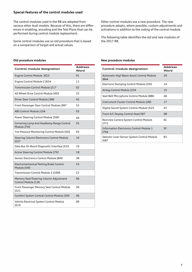
Special features of the control modules used
The control modules used in the R8 are adopted from various other Audi models. Because of this, there are differ-ences in enabling, encoding and the Test Plans that can be performed during control module replacement.
Some control modules use an old procedure that is based on a comparison of target and actual values.
Other control modules use a new procedure. The new procedure adopts, where possible, custom adjustments and activations in addition to the coding of the control module.
The following table identifies the old and new modules of the 2017 R8.
Old procedure modules New procedure modules
Control module designationAddress Word
Engine Control Module J623 01
Engine Control Module 2 J624 11
Transmission Control Module J217 02
All Wheel Drive Control Module J492 22
Driver Door Control Module J386 42
Front Passenger Door Control Module J387 52
ABS Control Module J104 03
Power Steering Control Module J500 44
Cornering Lamp And Headlamp Range Control Module J745
55
Tire Pressure Monitoring Control Module J502 65
Steering Column Electronics Control Module J527
16
Data Bus On Board Diagnostic Interface J533 19
Active Steering Control Module J792 18
Sensor Electronics Control Module J849 3B
Electromechanical Parking Brake Control Module J540
53
Transmission Control Module 2 J1006 C2
Memory Seat/Steering Column Adjustment Control Module J136
06
Front Passenger Memory Seat Control Module J521
36
Comfort System Central Control Module J393 46
Vehicle Electrical System Control Module J519
09
Control module designationAddress Word
Automatic High Beam Assist Control Module J844
20
Electronic Damping Control Module J250 14
Airbag Control Module J234 15
Seat Belt Microphone Control Module J886 A6
Instrument Cluster Control Module J285 17
Digital Sound System Control Module J525 47
Front A/C Display Control Head E87 08
Rearview Camera System Control Module J772
6C
Information Electronics Control Module 1 J794
5F
Selector Lever Sensor System Control Module J587
81

9
47 Ω 47 Ω
47 Ω 47 Ω
47 Ω 47 Ω
47 Ω 47 Ω
J849
J104
Branch 4
Branch 1
J533
Control module profiles
Designation Data Bus On Board Diagnostic Interface J533
Equipment Always installed
Installation location On the bulkhead at the top left
Task › Network system gateway › Controller for FlexRay bus › Diagnostic master › Energy management control
Address Word 19
Data bus communication › User of Convenience CAN, Powertrain CAN, Chassis CAN, Display and Operation CAN, Extended CAN, Diagnostic CAN and FlexRay buses.
› LIN master of Battery Monitoring Control Module J367 and Alternator C
Special features › Not a participant of the Modular Infotainment Platform (MIB) CAN › Not a participant of the MOST bus
Gateway
641_129
641_130
J533 is the controller for the FlexRay bus. All FlexRay control modules are connected to J533 within various branches. In this configuration J533 is referred to as the "active hub" or "active node". If only one control module is connected to a branch, this is referred to as a "point to point" connection.
Only two FlexRay users are connected to J533 in the Audi R8.
› ABS Control Module J104 is connected to branch 1. › Sensor Electronics Control Module J849 connected to
Branch 4.
This illustration differentiates between the bus positive cable (pink) and the bus negative cable (green) regarding the configuration of the control modules and thus reflects the actual situation.
Two resistors each having a resistance of 47 Ω (94 Ω in total) are connected to the end of each branch in the control module. After disconnecting the control module connector, the resistance value of 94 Ω can be measured by connecting a multimeter between the connecting pins of the bus positive and the bus negative at the relevant control module.
Data Bus On Board Diagnostic InterfaceJ533
Connection

10
Designation Vehicle Electrical System Control Module J519 / also referred to as BCM1 (Body Control Module 1)
Equipment Always installed
Installation location In the footwell on the right above the fuse box
Task Exterior lights master and activation of the front lights
Limp-home turn signal master in case of failure of J393
Interior lighting master
A/C functions › Activation of front seat heating › Activation of A/C Compressor Regulator Valve N280 and A/C Clutch N25
Integration functions › Parking
› Park assist › Activation of front and rear acoustic signal generators
Other functions › Reading input from the following senders/sensors/switches:
› Ambient temperature › New engine coolant, windshield washer fluid, brake fluid › Brake pad wear › Hood contact › Temperature sensor for seats › Start-stop button, rear spoiler, park assist, ESP, hazard warning flashers
› Activating the following actuators/control elements: › Signal horn › Windshield washer pump › Heating the windshield washer jets › Seat heater, front › Engine bay lights › Interior lights, glove box light
Address Word 09
Data bus communication › Convenience CAN user › J519 is the LIN master for:
› LIN 1: Light Switch E1, Rain/Light Recognition Sensor G397, Humidity Sensor G355 and Wiper Motor Control Module J400
› LIN 2: High Pressure Sensor G65, Humidity Sensor In Fresh Air Intake Duct G657, Air Quality Sensor G238, and Garage Door Opener Control Module J530
› LIN 3: Left and Right Auxiliary High Beam Bulbs M67 and M68
Special feature Fault finding notes:Regarding the LIN slave configuration, J519 has a duplicated pin. For example, LIN 1 is dis-tributed to 2 pins (A18, C2) which are, however, connected internally within the control module. This means that the control modules connected to pin C2 are also affected in the event of a short circuit to positive or negative at pin A18.
Onboard power supply
641_131
Vehicle Electrical System Control Module J519

11
641_132
Comfort System Central Control ModuleJ393
Designation Comfort System Central Control Module J393 / also referred to as BCM2 (Body Control Module 2)
Equipment Always installed
Installation location Below the parcel shelf on the left
Task Central locking system master
Turn signal master
Integration functions › Terminal management system › Entry and start authorization › Immobilizer (master) › Anti-theft alarm system
Other functions › Reading input from the following senders/sensors/switches:
› Brake light switch › Ignition starter button › P signal › Central locking antenna › Capacitive sensors of door handles › Entry and start authorization antennas
› Activating the following actuators/control elements: › Rear lights › Signal for dynamic turn signal operation › Rear hatch motor › Luggage compartment release › Fuel tank flap lock › Relay for external sockets › Terminal 15 relay › Luggage compartment lights › Rear lighting
Address Word 46
Data bus communication › Convenience CAN participant › J393 is the LIN master for:
› LIN 1: Garage Door Opener Control Head E284, Anti-Theft Alarm System Sensor G578 and Rear Spoiler Control Module J223
› LIN 2: Alarm Horn H12 › LIN 3: Electronic Steering Column Lock Control Module J764 and Anti-Theft Immobilizer
Reader Coil D2
Special features › J393 is the immobilizer system master › The central locking antenna is integrated with the control module printed circuit board
Comfort/convenience system
12
641_133
Driver Door Control ModuleJ386
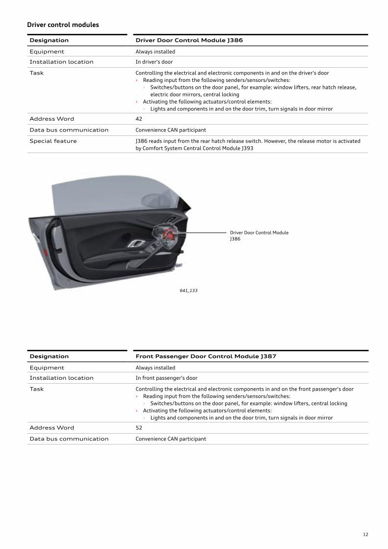
Designation Driver Door Control Module J386
Equipment Always installed
Installation location In driver's door
Task Controlling the electrical and electronic components in and on the driver's door › Reading input from the following senders/sensors/switches:
› Switches/buttons on the door panel, for example: window lifters, rear hatch release, electric door mirrors, central locking
› Activating the following actuators/control elements: › Lights and components in and on the door trim, turn signals in door mirror
Address Word 42
Data bus communication Convenience CAN participant
Special feature J386 reads input from the rear hatch release switch. However, the release motor is activated by Comfort System Central Control Module J393
Driver control modules
Designation Front Passenger Door Control Module J387
Equipment Always installed
Installation location In front passenger's door
Task Controlling the electrical and electronic components in and on the front passenger's door › Reading input from the following senders/sensors/switches:
› Switches/buttons on the door panel, for example: window lifters, central locking › Activating the following actuators/control elements:
› Lights and components in and on the door trim, turn signals in door mirror
Address Word 52
Data bus communication Convenience CAN participant

13
641_134
Memory Seat/Steering Column Adjustment Control ModuleJ136
Designation Memory Seat/Steering Column Adjustment Control Module J136
Equipment Optional equipment
Installation location Below the driver's seat
Task Controlling the driver seat adjustment functions › Reading input (senders/sensors):
› Seat adjustment sender › Pressure sensors
› Activating the following actuators/control elements: › Seat adjustment motors › Compressor for multi-contour seat
Address Word 36
Data bus communication Convenience CAN participant
Special features Regarding the position and pressure state of the seat pneumatics, the seat settings are assigned to the car key.A seat memory, in which various positions are stored using a switch on the door panel, is not available for the Audi R8.
Seat adjustment
Designation Front Passenger Memory Seat Control Module J521
Equipment Optional equipment
Installation location Below the front passenger seat (not shown)
Task Control of front passenger seat adjustment functions › Reading input (senders/sensors):
› Seat adjustment sender › Pressure sensors
› Activating the following actuators/control elements: › Seat adjustment motors › Compressor for multi-contour seat
Address Word 06
Data bus communication Convenience CAN participant
Special features As regards the position and pressure state of the seat pneumatics, the seat settings are assigned to the car key.A seat memory, in which various positions are stored using a switch on the door panel is not available for the Audi R8.
14
641_136
Selector Lever Sensor System Control ModuleJ587
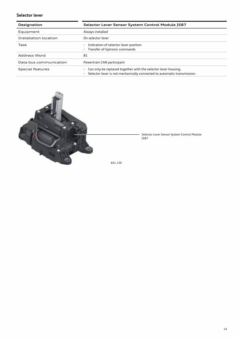
Designation Selector Lever Sensor System Control Module J587
Equipment Always installed
Installation location On selector lever
Task › Indication of selector lever position › Transfer of tiptronic commands
Address Word 81
Data bus communication Powertrain CAN participant
Special features › Can only be replaced together with the selector lever housing. › Selector lever is not mechanically connected to automatic transmission.
Selector lever
15
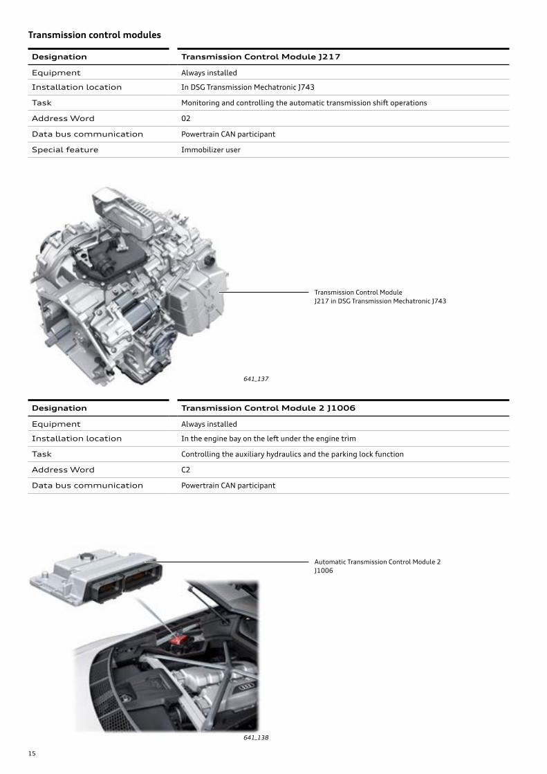
641_137
Transmission Control ModuleJ217 in DSG Transmission Mechatronic J743
641_138
Automatic Transmission Control Module 2J1006
Designation Transmission Control Module J217
Equipment Always installed
Installation location In DSG Transmission Mechatronic J743
Task Monitoring and controlling the automatic transmission shift operations
Address Word 02
Data bus communication Powertrain CAN participant
Special feature Immobilizer user
Transmission control modules
Designation Transmission Control Module 2 J1006
Equipment Always installed
Installation location In the engine bay on the left under the engine trim
Task Controlling the auxiliary hydraulics and the parking lock function
Address Word C2
Data bus communication Powertrain CAN participant
16
641_140
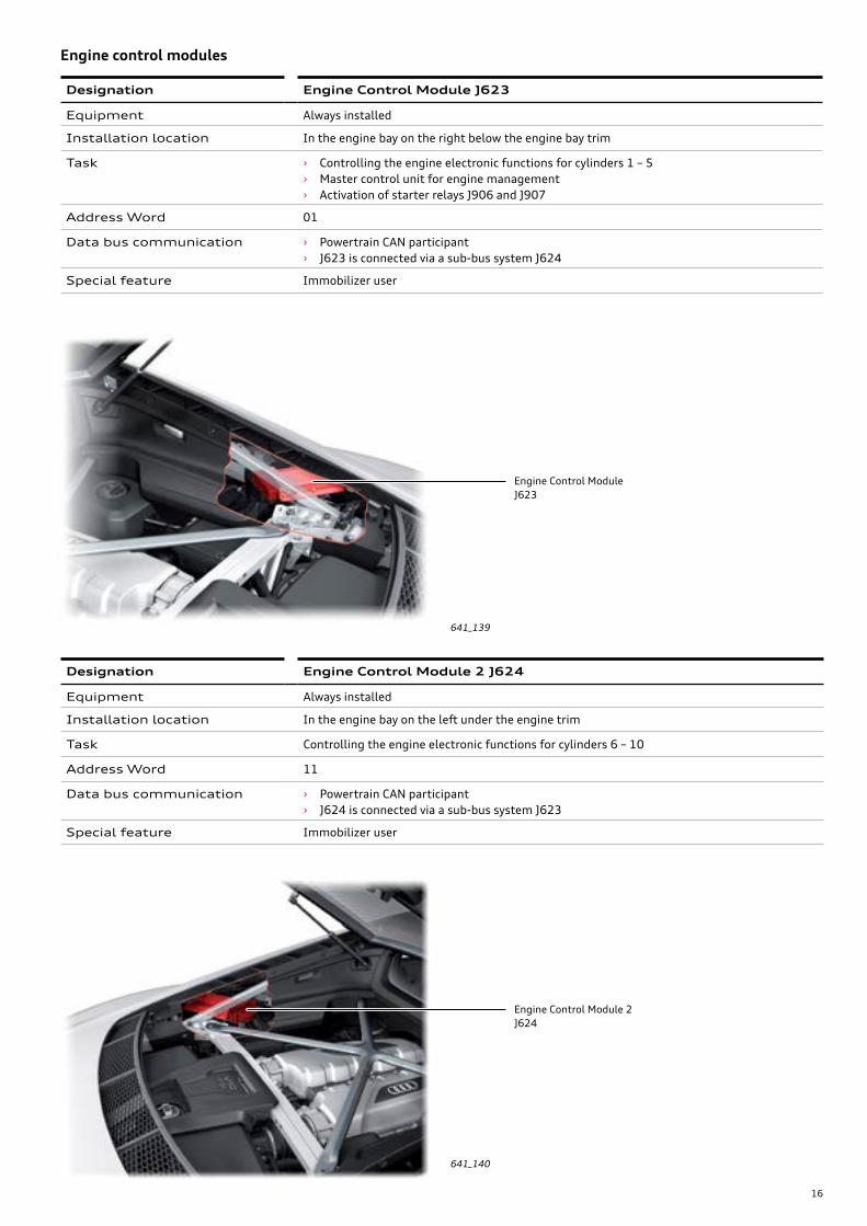
Engine Control Module 2J624
641_139
Engine Control ModuleJ623
Designation Engine Control Module J623
Equipment Always installed
Installation location In the engine bay on the right below the engine bay trim
Task › Controlling the engine electronic functions for cylinders 1 – 5 › Master control unit for engine management › Activation of starter relays J906 and J907
Address Word 01
Data bus communication › Powertrain CAN participant › J623 is connected via a sub-bus system J624
Special feature Immobilizer user
Engine control modules
Designation Engine Control Module 2 J624
Equipment Always installed
Installation location In the engine bay on the left under the engine trim
Task Controlling the engine electronic functions for cylinders 6 – 10
Address Word 11
Data bus communication › Powertrain CAN participant › J624 is connected via a sub-bus system J623
Special feature Immobilizer user
17
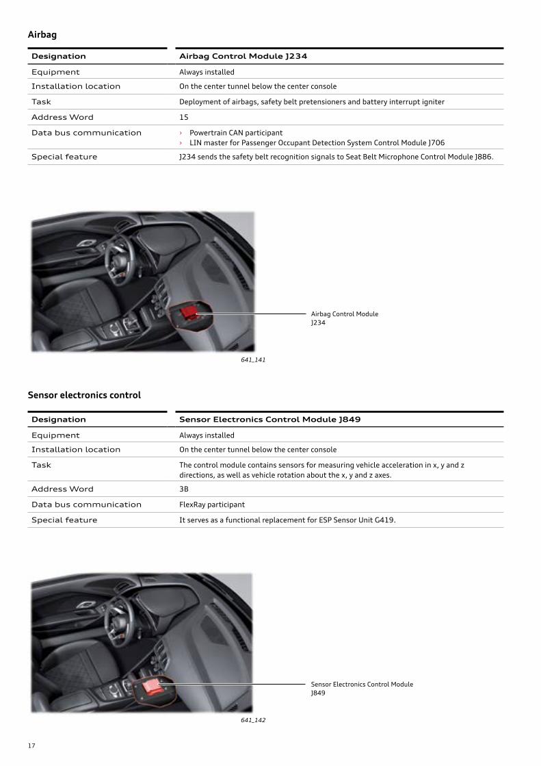
641_141
Airbag Control ModuleJ234
641_142
Sensor Electronics Control ModuleJ849
Designation Airbag Control Module J234
Equipment Always installed
Installation location On the center tunnel below the center console
Task Deployment of airbags, safety belt pretensioners and battery interrupt igniter
Address Word 15
Data bus communication › Powertrain CAN participant › LIN master for Passenger Occupant Detection System Control Module J706
Special feature J234 sends the safety belt recognition signals to Seat Belt Microphone Control Module J886.
Airbag
Designation Sensor Electronics Control Module J849
Equipment Always installed
Installation location On the center tunnel below the center console
Task The control module contains sensors for measuring vehicle acceleration in x, y and z directions, as well as vehicle rotation about the x, y and z axes.
Address Word 3B
Data bus communication FlexRay participant
Special feature It serves as a functional replacement for ESP Sensor Unit G419.
Sensor electronics control
18
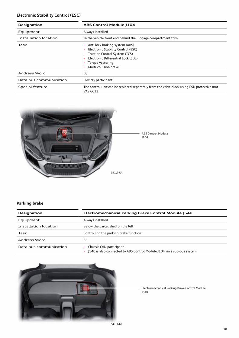
641_143
ABS Control ModuleJ104
641_144
Electromechanical Parking Brake Control ModuleJ540
Designation ABS Control Module J104
Equipment Always installed
Installation location In the vehicle front end behind the luggage compartment trim
Task › Anti lock braking system (ABS) › Electronic Stability Control (ESC) › Traction Control System (TCS) › Electronic Differential Lock (EDL) › Torque vectoring › Multi-collision brake
Address Word 03
Data bus communication FlexRay participant
Special feature The control unit can be replaced separately from the valve block using ESD protective mat VAS 6613.
Electronic Stability Control (ESC)
Designation Electromechanical Parking Brake Control Module J540
Equipment Always installed
Installation location Below the parcel shelf on the left
Task Controlling the parking brake function
Address Word 53
Data bus communication › Chassis CAN participant › J540 is also connected to ABS Control Module J104 via a sub-bus system
Parking brake

19
641_145
Power Steering Control ModuleJ500
641_146
Active Steering Control ModuleJ792
Designation Power Steering Control Module J500
Equipment Always installed
Installation location Connected to steering gear
Task › Power steering › Servotronic speed-responsive power steering › Corrective steering intervention with ESP
Address Word 44
Data bus communication Chassis CAN participant
Special features › The control module with power steering motor can only be replaced together with the steering gear.
Power steering
Designation Active Steering Control Module J792
Equipment Optional equipment
Installation location On the left hand module cross-member
Task The control module calculates the super-imposition angle required to implement the variable steering ratio.
Address Word 2B
Data bus communication Chassis CAN participant
Dynamic steering
20
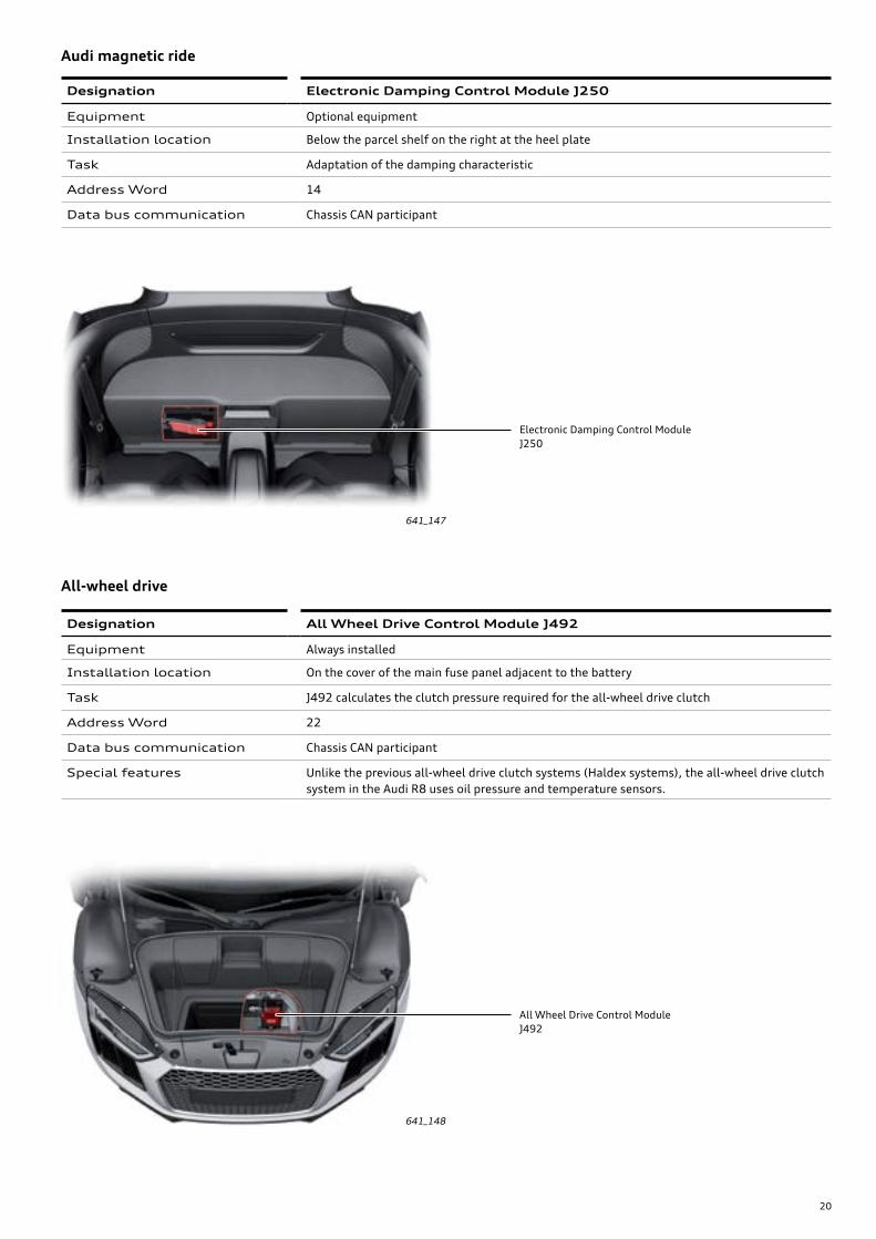
641_147
Electronic Damping Control ModuleJ250
641_148
All Wheel Drive Control ModuleJ492
Designation Electronic Damping Control Module J250
Equipment Optional equipment
Installation location Below the parcel shelf on the right at the heel plate
Task Adaptation of the damping characteristic
Address Word 14
Data bus communication Chassis CAN participant
Audi magnetic ride
Designation All Wheel Drive Control Module J492
Equipment Always installed
Installation location On the cover of the main fuse panel adjacent to the battery
Task J492 calculates the clutch pressure required for the all-wheel drive clutch
Address Word 22
Data bus communication Chassis CAN participant
Special features Unlike the previous all-wheel drive clutch systems (Haldex systems), the all-wheel drive clutch system in the Audi R8 uses oil pressure and temperature sensors.
All-wheel drive
21
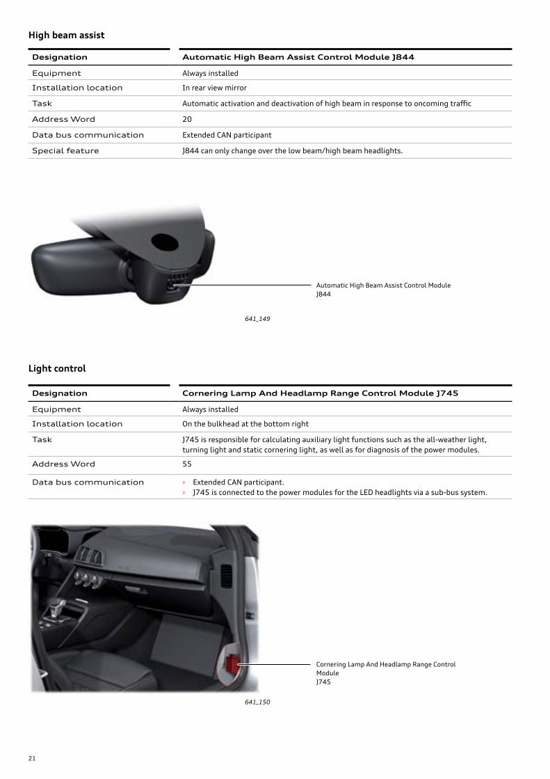
641_149
Automatic High Beam Assist Control ModuleJ844
641_150
Cornering Lamp And Headlamp Range Control ModuleJ745
Designation Automatic High Beam Assist Control Module J844
Equipment Always installed
Installation location In rear view mirror
Task Automatic activation and deactivation of high beam in response to oncoming traffic
Address Word 20
Data bus communication Extended CAN participant
Special feature J844 can only change over the low beam/high beam headlights.
High beam assist
Designation Cornering Lamp And Headlamp Range Control Module J745
Equipment Always installed
Installation location On the bulkhead at the bottom right
Task J745 is responsible for calculating auxiliary light functions such as the all-weather light, turning light and static cornering light, as well as for diagnosis of the power modules.
Address Word 55
Data bus communication › Extended CAN participant. › J745 is connected to the power modules for the LED headlights via a sub-bus system.
Light control
22
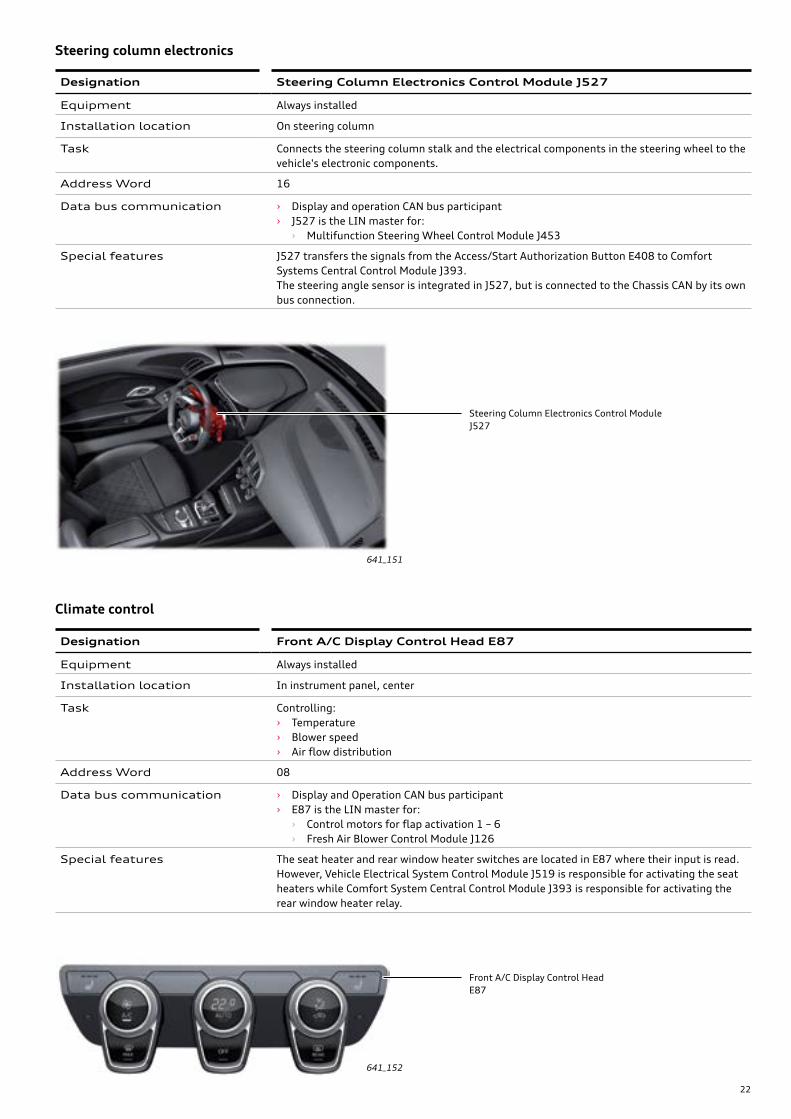
641_151
Steering Column Electronics Control ModuleJ527
641_152
Front A/C Display Control HeadE87
Designation Front A/C Display Control Head E87
Equipment Always installed
Installation location In instrument panel, center
Task Controlling: › Temperature › Blower speed › Air flow distribution
Address Word 08
Data bus communication › Display and Operation CAN bus participant › E87 is the LIN master for:
› Control motors for flap activation 1 – 6 › Fresh Air Blower Control Module J126
Special features The seat heater and rear window heater switches are located in E87 where their input is read. However, Vehicle Electrical System Control Module J519 is responsible for activating the seat heaters while Comfort System Central Control Module J393 is responsible for activating the rear window heater relay.
Climate control
Designation Steering Column Electronics Control Module J527
Equipment Always installed
Installation location On steering column
Task Connects the steering column stalk and the electrical components in the steering wheel to the vehicle's electronic components.
Address Word 16
Data bus communication › Display and operation CAN bus participant › J527 is the LIN master for:
› Multifunction Steering Wheel Control Module J453
Special features J527 transfers the signals from the Access/Start Authorization Button E408 to Comfort Systems Central Control Module J393.The steering angle sensor is integrated in J527, but is connected to the Chassis CAN by its own bus connection.
Steering column electronics
23
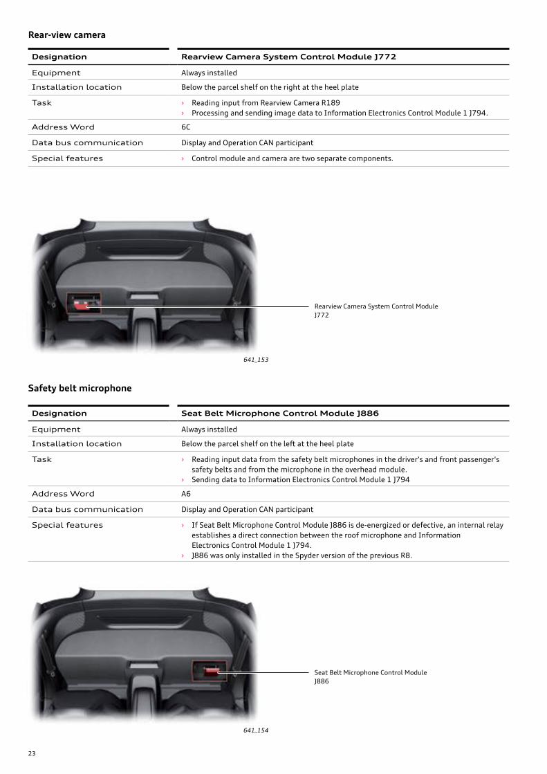
641_153
Rearview Camera System Control ModuleJ772
641_154
Seat Belt Microphone Control ModuleJ886
Designation Rearview Camera System Control Module J772
Equipment Always installed
Installation location Below the parcel shelf on the right at the heel plate
Task › Reading input from Rearview Camera R189 › Processing and sending image data to Information Electronics Control Module 1 J794.
Address Word 6C
Data bus communication Display and Operation CAN participant
Special features › Control module and camera are two separate components.
Rear-view camera
Designation Seat Belt Microphone Control Module J886
Equipment Always installed
Installation location Below the parcel shelf on the left at the heel plate
Task › Reading input data from the safety belt microphones in the driver's and front passenger's safety belts and from the microphone in the overhead module.
› Sending data to Information Electronics Control Module 1 J794
Address Word A6
Data bus communication Display and Operation CAN participant
Special features › If Seat Belt Microphone Control Module J886 is de-energized or defective, an internal relay establishes a direct connection between the roof microphone and Information Electronics Control Module 1 J794.
› J886 was only installed in the Spyder version of the previous R8.
Safety belt microphone

24
641_155
Tire Pressure Monitoring Control ModuleJ502
641_156
Instrument Cluster Control ModuleJ285
Designation Instrument Cluster Control Module J285
Equipment Always installed / Audi virtual cockpit
Installation location In instrument panel
Task Display of information relevant to the driver
Address Word 17
Data bus communication › Display and Operation CAN participant › MOST participant
Special features › J285 is connected the Information Electronics Control Module 1 J794 with an LVDS line. › The instrument cluster is not integrated with the immobilizer in the Audi R8.
Instrument cluster
Designation Tire Pressure Monitoring Control Module J502
Equipment Always installed
Installation location Below a flap in the underbody on the left
Task › Pick-up and evaluation of signals from Tire Pressure Sensors G222, G223, G224 und G225 › Indication of tire pressures or issuance of warnings to Information Electronics Control
Module 1 J794
Address Word 65
Data bus communication Display and Operation CAN participant
Special features › The control module sends a PWM signal by cable to the trigger senders in the wheel arches with the command to query the pressure and temperature sensors in the wheel rims.
› The sensors in the tire valves send the data wirelessly to the control module.
Tire pressure monitoring
25
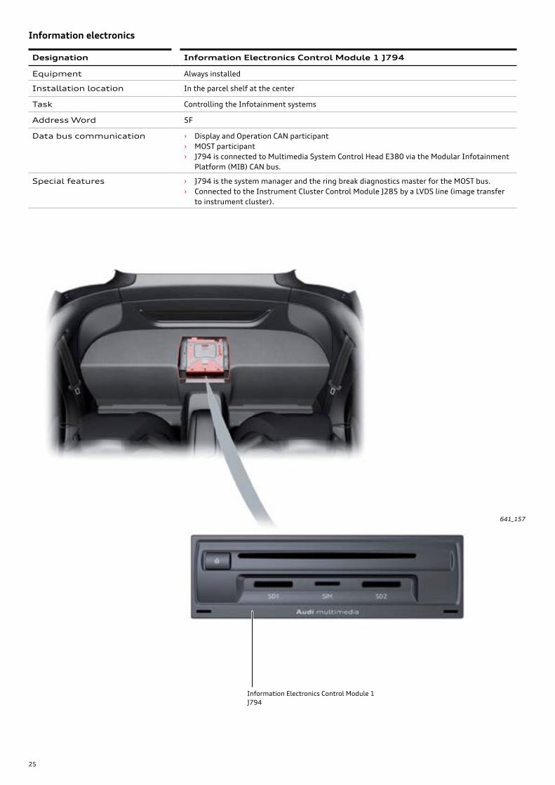
641_157
Information Electronics Control Module 1J794
Designation Information Electronics Control Module 1 J794
Equipment Always installed
Installation location In the parcel shelf at the center
Task Controlling the Infotainment systems
Address Word 5F
Data bus communication › Display and Operation CAN participant › MOST participant › J794 is connected to Multimedia System Control Head E380 via the Modular Infotainment
Platform (MIB) CAN bus.
Special features › J794 is the system manager and the ring break diagnostics master for the MOST bus. › Connected to the Instrument Cluster Control Module J285 by a LVDS line (image transfer
to instrument cluster).
Information electronics
26
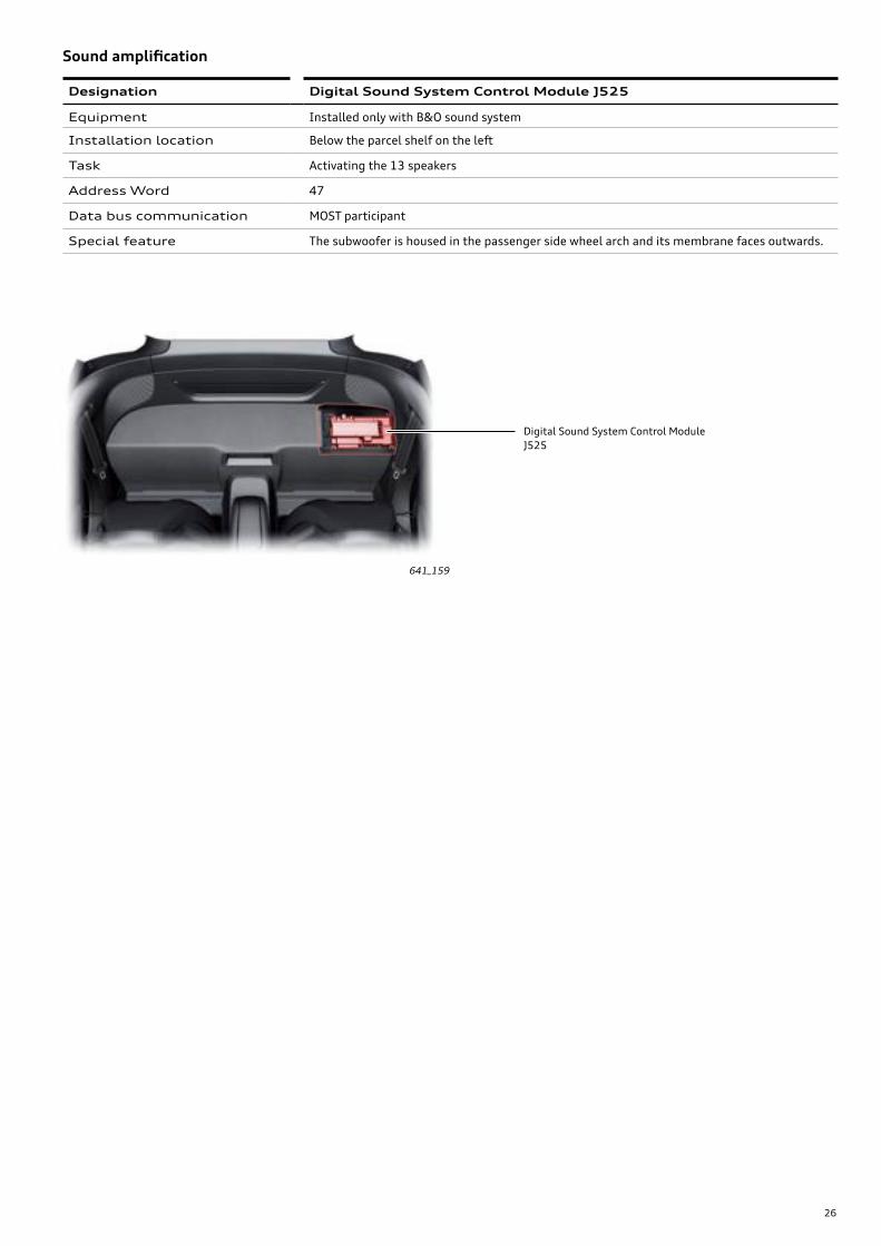
641_159
Digital Sound System Control ModuleJ525
Designation Digital Sound System Control Module J525
Equipment Installed only with B&O sound system
Installation location Below the parcel shelf on the left
Task Activating the 13 speakers
Address Word 47
Data bus communication MOST participant
Special feature The subwoofer is housed in the passenger side wheel arch and its membrane faces outwards.
Soundamplification
27
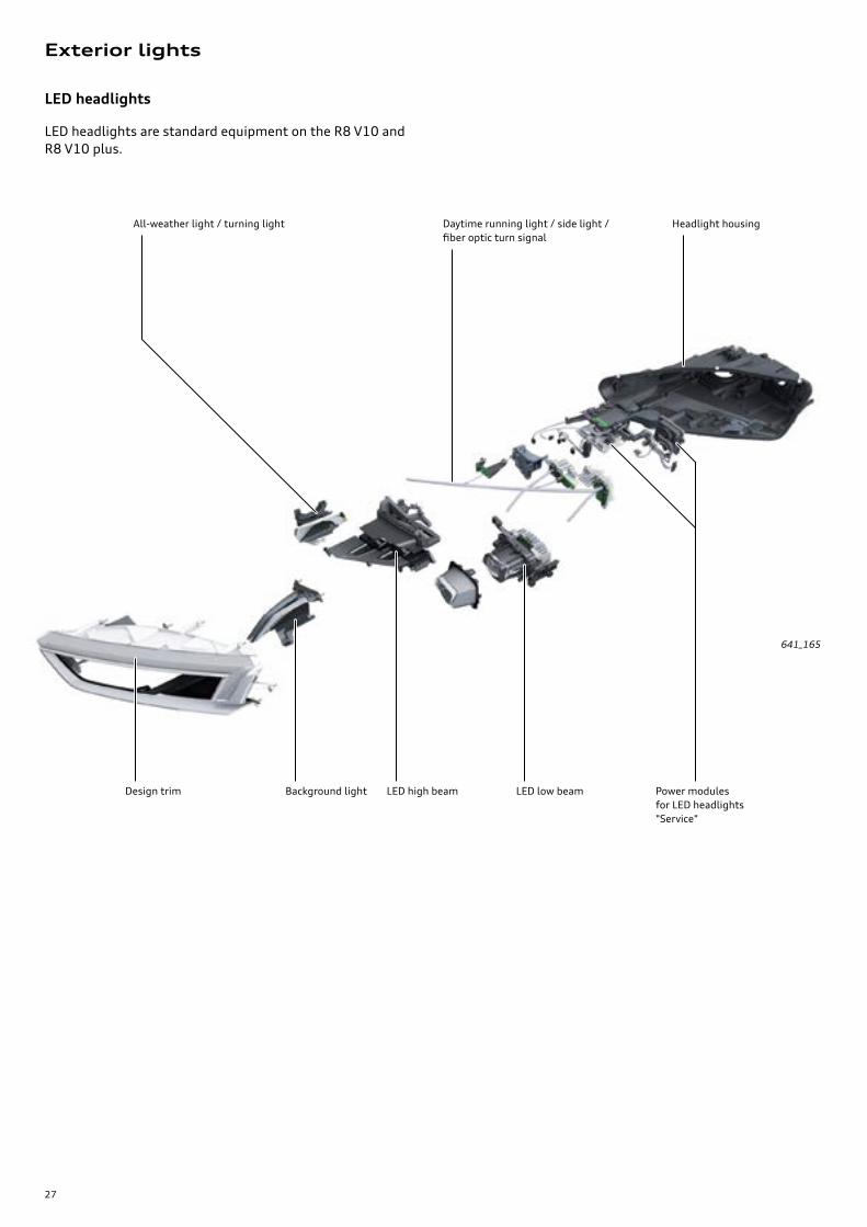
Exterior lights
LED headlights
LED headlights are standard equipment on the R8 V10 and R8 V10 plus.
641_165
Headlight housing
Power modules for LED headlights "Service"
Daytime running light / side light / fiber optic turn signal
LED low beamLED high beam
All-weather light / turning light
Background lightDesign trim
28
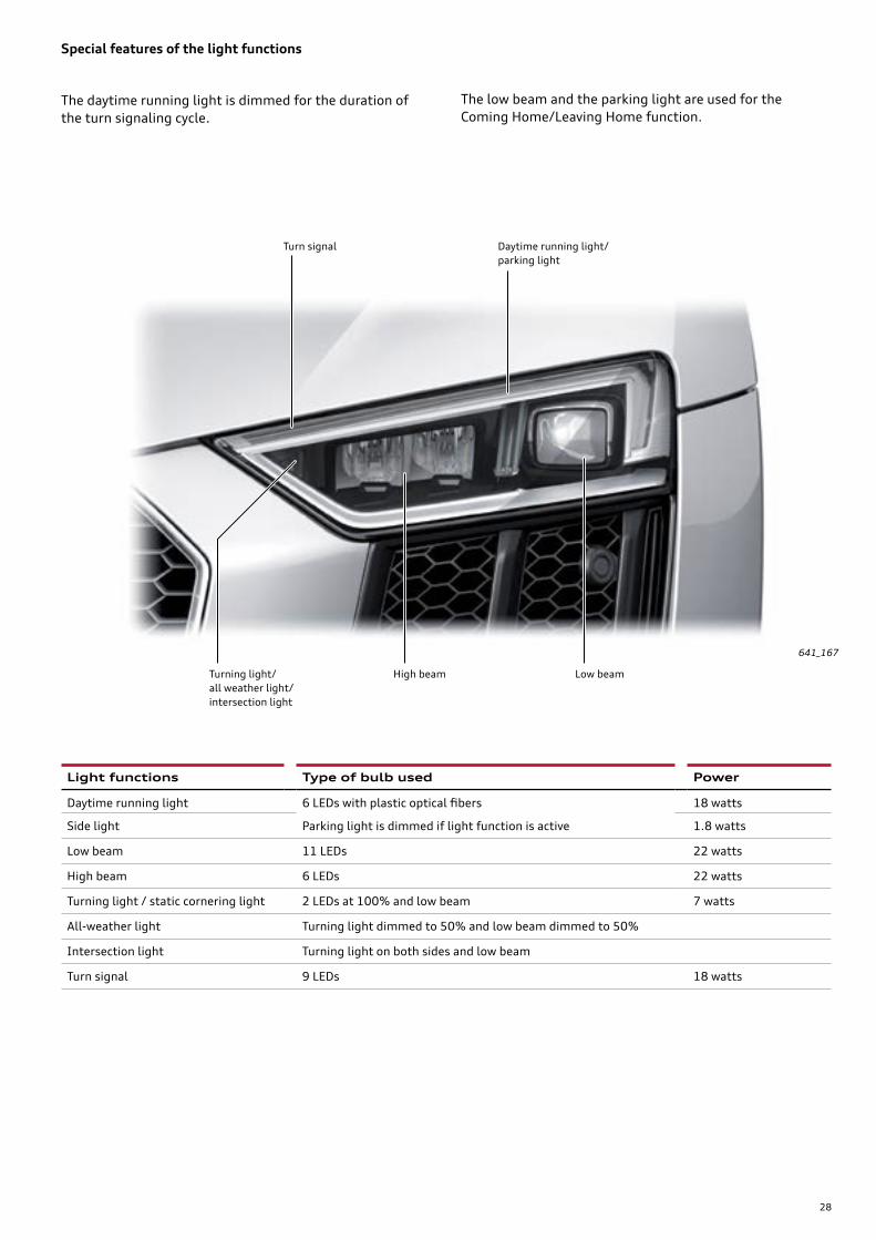
Light functions Type of bulb used Power
Daytime running light 6 LEDs with plastic optical fibers 18 watts
Side light Parking light is dimmed if light function is active 1.8 watts
Low beam 11 LEDs 22 watts
High beam 6 LEDs 22 watts
Turning light / static cornering light 2 LEDs at 100% and low beam 7 watts
All-weather light Turning light dimmed to 50% and low beam dimmed to 50%
Intersection light Turning light on both sides and low beam
Turn signal 9 LEDs 18 watts
Special features of the light functions
The daytime running light is dimmed for the duration of the turn signaling cycle.
The low beam and the parking light are used for the Coming Home/Leaving Home function.
High beam Low beam
Daytime running light/ parking light
Turn signal
Turning light/ all weather light/ intersection light
641_167
29
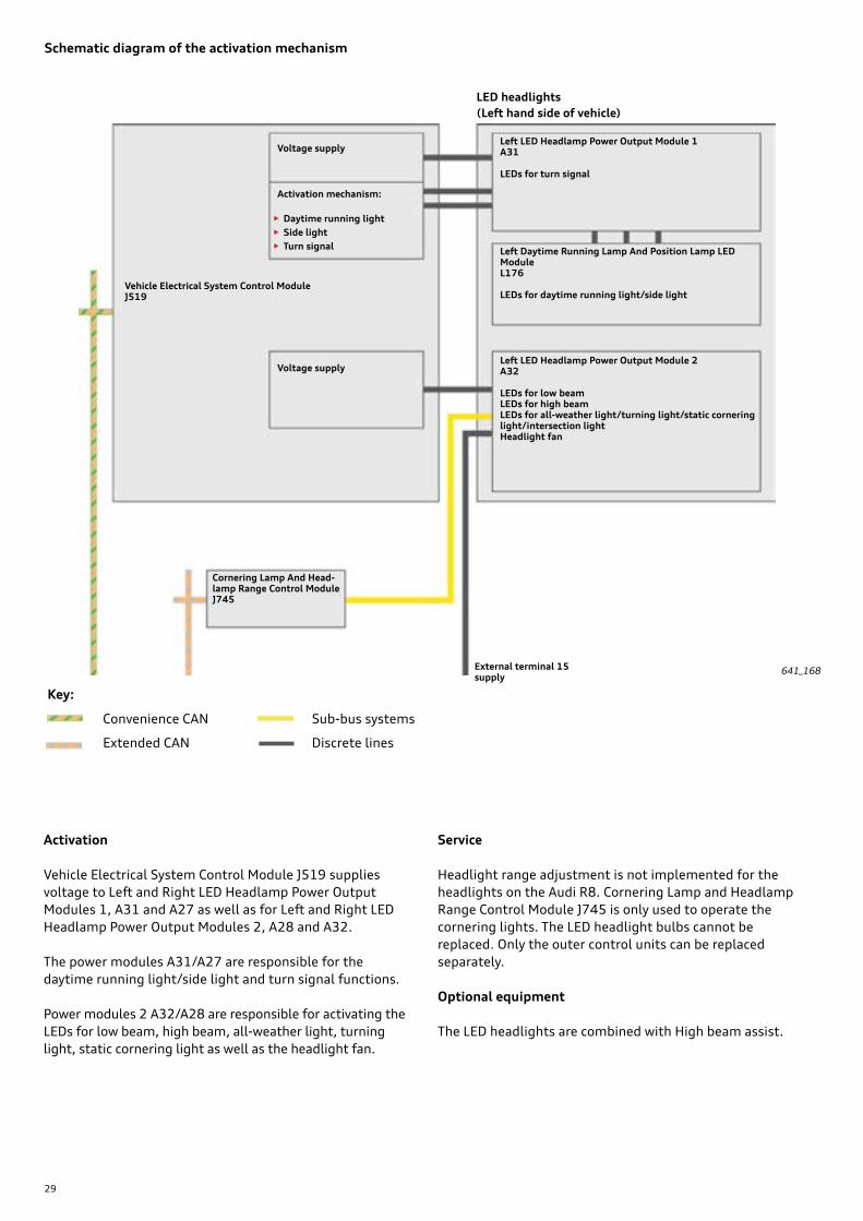
Schematic diagram of the activation mechanism
641_168
Activation
Vehicle Electrical System Control Module J519 supplies voltage to Left and Right LED Headlamp Power Output Modules 1, A31 and A27 as well as for Left and Right LED Headlamp Power Output Modules 2, A28 and A32.
The power modules A31/A27 are responsible for the daytime running light/side light and turn signal functions.
Power modules 2 A32/A28 are responsible for activating the LEDs for low beam, high beam, all-weather light, turning light, static cornering light as well as the headlight fan.
Service
Headlight range adjustment is not implemented for the headlights on the Audi R8. Cornering Lamp and Headlamp Range Control Module J745 is only used to operate the cornering lights. The LED headlight bulbs cannot be replaced. Only the outer control units can be replaced separately.
Optional equipment
The LED headlights are combined with High beam assist.
External terminal 15 supply
Left LED Headlamp Power Output Module 1A31
LEDs for turn signal
Left Daytime Running Lamp And Position Lamp LED ModuleL176
LEDs for daytime running light/side light
Left LED Headlamp Power Output Module 2A32
LEDs for low beamLEDs for high beamLEDs for all-weather light/turning light/static cornering light/intersection lightHeadlight fan
Voltage supply
Voltage supply
Activation mechanism:
• Daytime running light• Side light• Turn signal
LED headlights(Left hand side of vehicle)
Vehicle Electrical System Control Module J519
Cornering Lamp And Head-lamp Range Control ModuleJ745
Convenience CAN
Extended CAN
Sub-bus systems
Discrete lines
Key:

30
Tail lights
The tail lights of the Audi R8 are integrated in the rear body side sections and border the bumper cover or the ventila-tion grilles at the bottom. Only LEDs are used for lighting.
The sequential turn signal function has an additional elec-tronic module in the tail light. The sidemarkers for the North American Region are not integrated in the tail lights, but rather have been transferred to the body side sections of the vehicle as separate lights.
Activation
The tail lights are activated by Comfort System Central Control Module J393. J393 also determines whether sequential or conventional turn signaling is required.
The tail light LEDs are used for the Coming Home/Leaving Home function.
Service
Neither individual LEDs nor the electronic components for "dynamic turn signal operation" can be replaced on the tail lights. In case of damage, the entire tail light must be replaced.
Brake light
Turn signalTail lightBack-up light
Rear fog light
Tail light
641_173

31
Audi drive select
Functional characteristics
The Audi R8 is equipped with the Audi drive select system.With Audi drive select, it is possible to modify the vehicle characteristic. The mode can be changed when the car is stationary or while driving.
The systems shown in the illustration below can be con-trolled via the Audi drive select system.
In the Audi R8 the driver can select between the following drive modes: Comfort, Auto, Dynamic, Individual and Performance.
The Audi drive select system can be set using the Audi drive select button in the steering wheel or using the Car menu via Multimedia System Control Head E380. The selected mode is always displayed in the Audi virtual cockpit.
641_174
Steering Variable steering torque
ESC Variable characteristic
Automatic transmissionVariable shift program
Engine soundSwitchable flap control
drive selectAccessible via Car menu; select with rotary push knob
Dynamic steering Variable steering ratios
Accelerator/engine Variable characteristic
All-wheel drive Variable power distribution
Damper control Variable damper rate
32
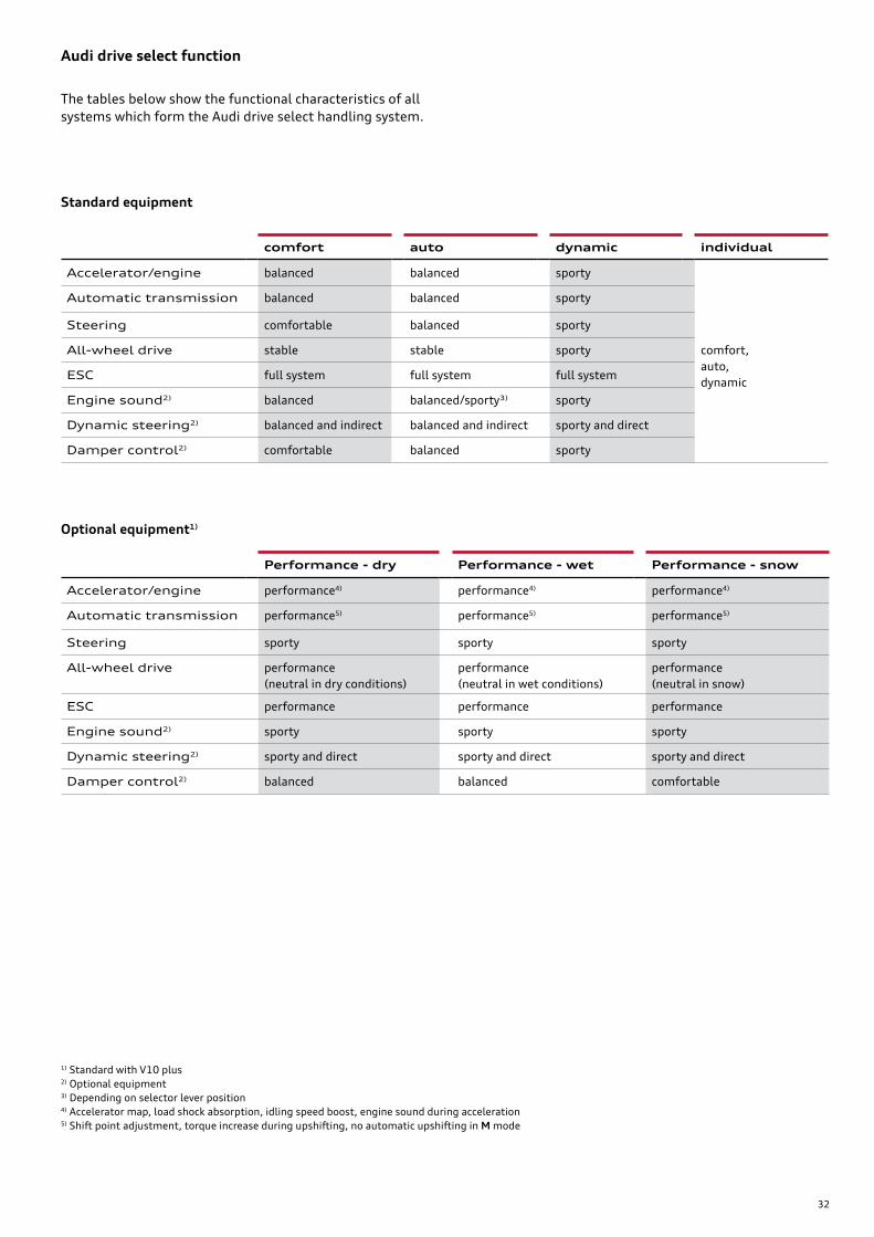
comfort auto dynamic individual
Accelerator/engine balanced balanced sporty
Automatic transmission balanced balanced sporty
Steering comfortable balanced sporty
All-wheel drive stable stable sporty comfort, auto, dynamic
ESC full system full system full system
Engine sound2) balanced balanced/sporty3) sporty
Dynamic steering2) balanced and indirect balanced and indirect sporty and direct
Damper control2) comfortable balanced sporty
Audi drive select function
Performance - dry Performance - wet Performance - snow
Accelerator/engine performance4) performance4) performance4)
Automatic transmission performance5) performance5) performance5)
Steering sporty sporty sporty
All-wheel drive performance (neutral in dry conditions)
performance (neutral in wet conditions)
performance (neutral in snow)
ESC performance performance performance
Engine sound2) sporty sporty sporty
Dynamic steering2) sporty and direct sporty and direct sporty and direct
Damper control2) balanced balanced comfortable
Standard equipment
Optional equipment1)
1) Standard with V10 plus2) Optional equipment3) Depending on selector lever position4) Accelerator map, load shock absorption, idling speed boost, engine sound during acceleration5) Shift point adjustment, torque increase during upshifting, no automatic upshifting in M mode
The tables below show the functional characteristics of all systems which form the Audi drive select handling system.
33
Multifunction steering wheel
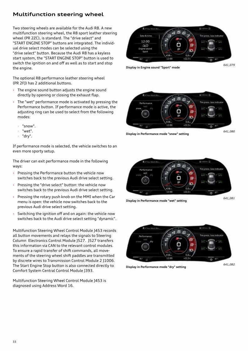
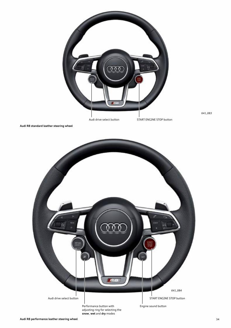
Two steering wheels are available for the Audi R8. A new multifunction steering wheel, the R8 sport leather steering wheel (PR 2ZC), is standard. The "drive select" and "START ENGINE STOP" buttons are integrated. The individ-ual drive select modes can be selected using the "drive select" button. Because the Audi R8 has a keyless start system, the "START ENGINE STOP" button is used to switch the ignition on and off as well as to start and stop the engine.
The optional R8 performance leather steering wheel (PR 2FJ) has 2 additional buttons.
› The engine sound button adjusts the engine sound directly by opening or closing the exhaust flap.
› The "wet" performance mode is activated by pressing the Performance button. If performance mode is active, the adjusting ring can be used to select from the following modes:
› "snow". › "wet". › "dry".
If performance mode is selected, the vehicle switches to an even more sporty setup.
The driver can exit performance mode in the following ways:
› Pressing the Performance button the vehicle now switches back to the previous Audi drive select setting.
› Pressing the "drive select" button: the vehicle now switches back to the previous Audi drive select setting.
› Pressing the rotary push knob on the MMI when the Car menu is open: the vehicle now switches back to the previous Audi drive select setting.
› Switching the ignition off and on again: the vehicle now switches back to the Audi drive select setting "dynamic".
Multifunction Steering Wheel Control Module J453 records all button movements and relays the signals to Steering Column Electronics Control Module J527. J527 transfers this information via CAN to the relevant control modules. To ensure a rapid transfer of shift commands, all move-ments of the steering wheel shift paddles are transmitted by discrete wires to Transmission Control Module 2 J1006. The Start Engine Stop button is also connected directly to Comfort System Central Control Module J393.
Multifunction Steering Wheel Control Module J453 is diagnosed using Address Word 16.
641_079
641_080
641_081
641_082
Display in Engine sound "Sport" mode
Display in Performance mode "snow" setting
Display in Performance mode "wet" setting
Display in Performance mode "dry" setting
Date & time
kph
150 km
12:00 +22,5°C
Engine soundSport
85 °C 87 °C
438km 0,0km
12:00
Tire press. loss indicator
24 °C
24 °C
24 °C
24 °C
2.2 bar
2.2 bar
2.2 bar
2.2 bar
Performance
kph
150 km
12:00 +22,5°C
wet
85 °C 87 °C
438km 0,0km
Tire press. loss indicator
24 °C
24 °C
24 °C
24 °C
2.2 bar
2.2 bar
2.2 bar
2.2 barsnow dry
Performance
kph
150 km
12:00 +22,5°C
wet
85 °C 87 °C
438km 0,0km
Tire press. loss indicator
24 °C
24 °C
24 °C
24 °C
2.2 bar
2.2 bar
2.2 bar
2.2 barsnow dry
Performance
kph
150 km
12:00 +22,5°C
wet
85 °C 87 °C
438km 0,0km
Tire press. loss indicator
24 °C
24 °C
24 °C
24 °C
2.2 bar
2.2 bar
2.2 bar
2.2 barsnow dry
34
641_084
641_083
Audi drive select button
Engine sound button
START ENGINE STOP button
Audi drive select button START ENGINE STOP button
Performance button with adjusting ring for selecting the snow, wet and dry modes
Audi R8 standardleathersteeringwheel
Audi R8 performanceleathersteeringwheel
35
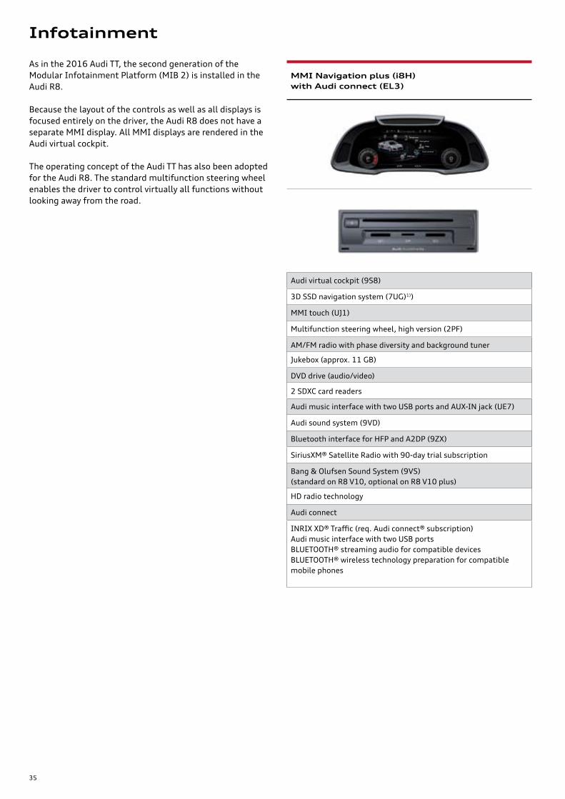
As in the 2016 Audi TT, the second generation of the Modular Infotainment Platform (MIB 2) is installed in the Audi R8.
Because the layout of the controls as well as all displays is focused entirely on the driver, the Audi R8 does not have a separate MMI display. All MMI displays are rendered in the Audi virtual cockpit.
The operating concept of the Audi TT has also been adopted for the Audi R8. The standard multifunction steering wheel enables the driver to control virtually all functions without looking away from the road.
MMI Navigation plus (i8H) with Audi connect (EL3)
Audi virtual cockpit (9S8)
3D SSD navigation system (7UG)1))
MMI touch (UJ1)
Multifunction steering wheel, high version (2PF)
AM/FM radio with phase diversity and background tuner
Jukebox (approx. 11 GB)
DVD drive (audio/video)
2 SDXC card readers
Audi music interface with two USB ports and AUX-IN jack (UE7)
Audi sound system (9VD)
Bluetooth interface for HFP and A2DP (9ZX)
SiriusXM® Satellite Radio with 90-day trial subscription
Bang & Olufsen Sound System (9VS) (standard on R8 V10, optional on R8 V10 plus)
HD radio technology
Audi connect
INRIX XD® Traffic (req. Audi connect® subscription)Audi music interface with two USB portsBLUETOOTH® streaming audio for compatible devicesBLUETOOTH® wireless technology preparation for compatible mobile phones
Telephone
Navigation
Map
Audi connect
Settings
kph
150 km
12:00 +22,5°C
Infotainment

36
Sound systems
The Audi sound system is standard equipment on the R8 V10 plus. It has five speakers and delivers a total of 140 watts power. The speakers are powered through Informa-tion Electronics Control Module 1 J794 and can be diag-nosed individually.
641_073
Audi sound system
Left Front Treble SpeakerR20
Center SpeakerR208
Right Front Treble SpeakerR22
Left FrontBass Speaker R21
Right Front Bass SpeakerR23
37
641_074
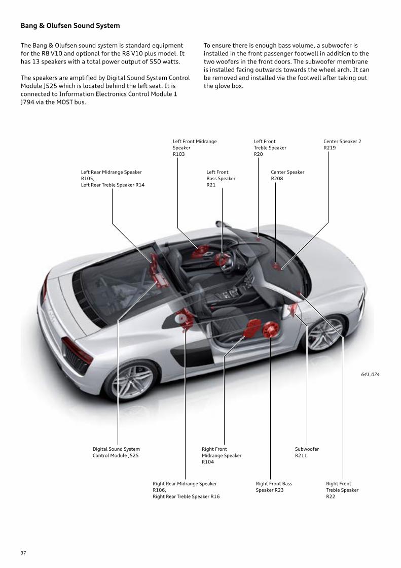
Bang & Olufsen Sound System
The Bang & Olufsen sound system is standard equipment for the R8 V10 and optional for the R8 V10 plus model. It has 13 speakers with a total power output of 550 watts.
The speakers are amplified by Digital Sound System Control Module J525 which is located behind the left seat. It is connected to Information Electronics Control Module 1 J794 via the MOST bus.
To ensure there is enough bass volume, a subwoofer is installed in the front passenger footwell in addition to the two woofers in the front doors. The subwoofer membrane is installed facing outwards towards the wheel arch. It can be removed and installed via the footwell after taking out the glove box.
Center Speaker 2 R219
Left Front Treble Speaker R20
Center SpeakerR208
Right Front Treble Speaker R22
Left Front Bass Speaker R21
Left Front Midrange Speaker R103
Right Front Bass Speaker R23
Right Front Midrange Speaker R104
Right Rear Midrange Speaker R106,Right Rear Treble Speaker R16
Left Rear Midrange Speaker R105,Left Rear Treble Speaker R14
SubwooferR211
Digital Sound System Control Module J525
38
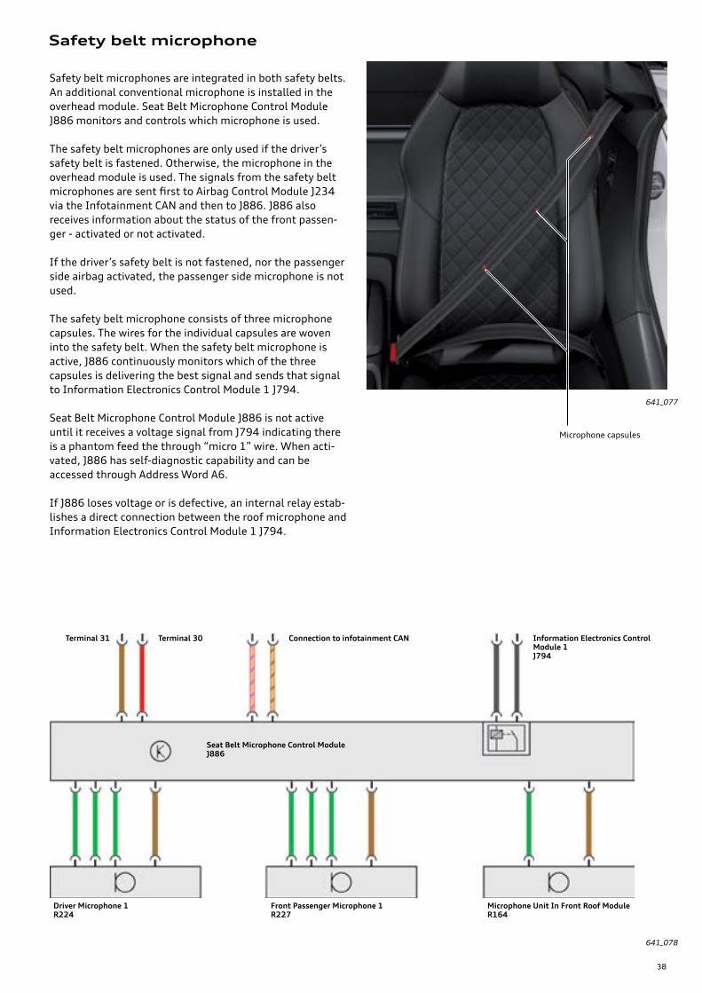
Safety belt microphone
Safety belt microphones are integrated in both safety belts. An additional conventional microphone is installed in the overhead module. Seat Belt Microphone Control Module J886 monitors and controls which microphone is used.
The safety belt microphones are only used if the driver’s safety belt is fastened. Otherwise, the microphone in the overhead module is used. The signals from the safety belt microphones are sent first to Airbag Control Module J234 via the Infotainment CAN and then to J886. J886 also receives information about the status of the front passen-ger - activated or not activated.
If the driver’s safety belt is not fastened, nor the passenger side airbag activated, the passenger side microphone is not used.
The safety belt microphone consists of three microphone capsules. The wires for the individual capsules are woven into the safety belt. When the safety belt microphone is active, J886 continuously monitors which of the three capsules is delivering the best signal and sends that signal to Information Electronics Control Module 1 J794.
Seat Belt Microphone Control Module J886 is not active until it receives a voltage signal from J794 indicating there is a phantom feed the through “micro 1” wire. When acti-vated, J886 has self-diagnostic capability and can be accessed through Address Word A6.
If J886 loses voltage or is defective, an internal relay estab-lishes a direct connection between the roof microphone and Information Electronics Control Module 1 J794.
641_078
641_077
Seat Belt Microphone Control Module J886
Driver Microphone 1R224
Front Passenger Microphone 1R227
Microphone Unit In Front Roof ModuleR164
Terminal 31 Terminal 30 Connection to infotainment CAN Information Electronics Control Module 1J794
Microphone capsules
39
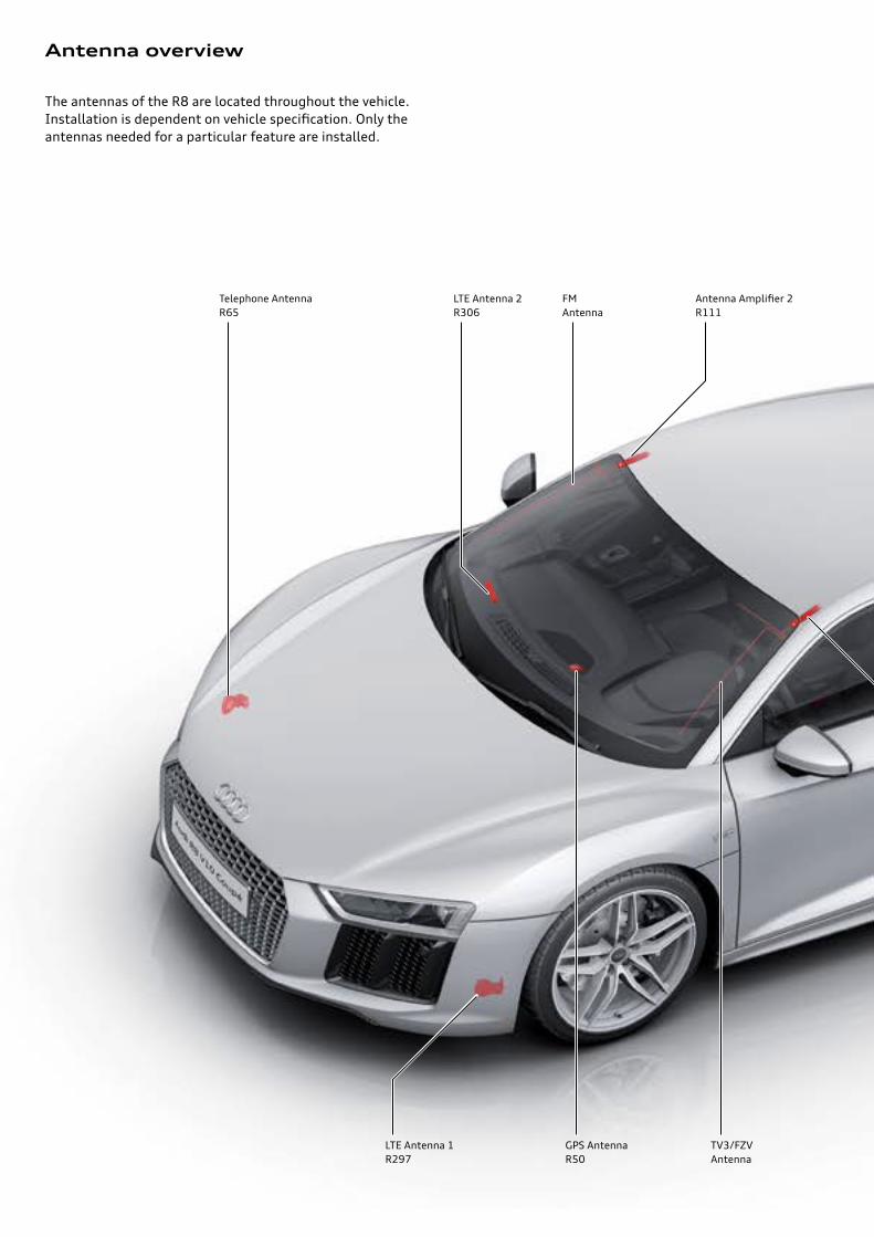
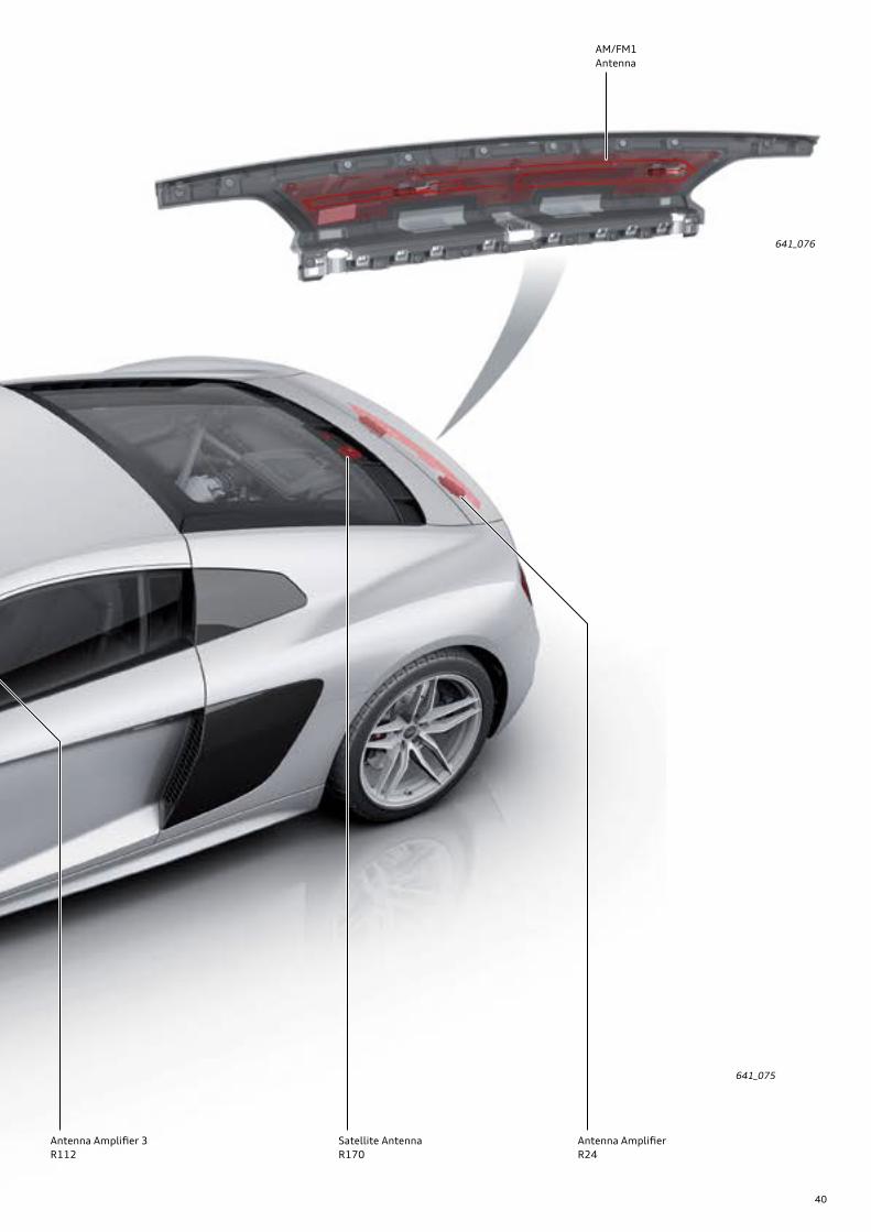
Antenna overview
The antennas of the R8 are located throughout the vehicle. Installation is dependent on vehicle specification. Only the antennas needed for a particular feature are installed.
LTE Antenna 2R306
LTE Antenna 1R297
FM Antenna
TV3/FZV Antenna
Antenna Amplifier 2R111
Telephone AntennaR65
GPS AntennaR50
40
641_075
641_076
Antenna AmplifierR24
Antenna Amplifier 3R112
AM/FM1 Antenna
Satellite AntennaR170
41
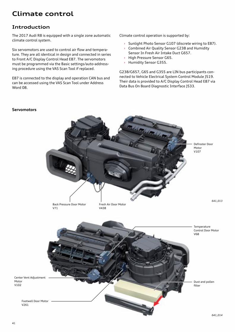
Introduction
The 2017 Audi R8 is equipped with a single zone automatic climate control system.
Six servomotors are used to control air flow and tempera-ture. They are all identical in design and connected in series to Front A/C Display Control Head E87. The servomotors must be programmed via the Basic settings/auto-address-ing procedure using the VAS Scan Tool if replaced.
E87 is connected to the display and operation CAN bus and can be accessed using the VAS Scan Tool under Address Word 08.
Climate control operation is supported by:
› Sunlight Photo Sensor G107 (discrete wiring to E87). › Combined Air Quality Sensor G238 and Humidity
Sensor In Fresh Air Intake Duct G657. › High Pressure Sensor G65. › Humidity Sensor G355.
G238/G657, G65 and G355 are LIN bus participants con-nected to Vehicle Electrical System Control Module J519. Their data is provided to A/C Display Control Head E87 via Data Bus On Board Diagnostic Interface J533.
Servomotors
Back Pressure Door Motor V71
Fresh Air Door MotorV438
Defroster Door MotorV107
Footwell Door MotorV261
Temperature Control Door MotorV68
Center Vent Adjustment MotorV102
641_013
641_014
Dust and pollen filter
Climate control

42
E87 has three turn-and-push knobs. The center turn-and-push knob has a display which can be used to set the cabin temperature.
The seat heater buttons are located in a row of buttons above the turn-and-push knob.
E87 has two cabin temperature sensors. Depending on software version of control unit E87, either one of or both of the sensors may be active. If both the temperature sensors are active, the hardware computes a valid value from the data provided.
Front A/C Display Control Head E87
Temperature adjustment display
ButtonsLeft seat heater button
Interior temperature sensorInterior temperature sensor
Right seat heater button
641_015
Passenger compartment ventilation
As with all Audi models, the R8 has a forced air ventilation system. This prevents the build-up of over-pressure when closing a door.
Air flows from behind the parcel shelf towards the ‘B’ pillars and then through the speaker trims towards the Audi Space Frame body.
The air flows through body intakes to both vent trims located behind the doors on the exterior of the lower ‘B’ pillars.
Out vent trims
Inner speaker trims
641_018

43
Refrigerant circuit
The refrigerant circuit has two condensers. They are identi-cal in design and like the two outer engine coolant radia-tors, are installed at a rotation angle of 180 degrees. The refrigerant tube to and from the expansion valve is the familiar internal heat exchanger design (coaxial refrigerant line).
The A/C compressor has a direct clutch and is driven by the engine through a drive shaft. An overload cut-out that can interrupt power flow between the engine and compressor in case of compressor failure is integrated in the A/C clutch. R134 refrigerant is used in this vehicle.
After replacing the components of the refrigerant circuit, care must be taken to ensure that the system is filled with the correct level of refrigerant oil. The following quantities of refrigerant oil must be added to the refrigerant circuit after replacing the following components:
› Replacing a single condenser: + 0.33 oz (10 ccm). › Replacing both condensers: + 0.66 oz (20 ccm). › Replacing the evaporator: + 0.66 oz (20 ccm).
The high and low pressure service connections for refilling refrigerant are located near the receiver/drier and can be accessed through a flap in the luggage compartment.
Service operations
Coaxial refrigerant line
Condensers A/C compressorCondensation drain
Service connectionsDrier
641_017
Front A/C Display Control Head E87

44
Inspection and maintenance
NoteThe specifications in the current service literature generally apply. It is important to comply with the approved oil standard when changing the oil.
Overview of maintenance intervals for vehicles in the USA
641_125
10,000 miles /1 year
20,000 miles /2 years
30,000 miles /3 years
40,000 miles /4 years
50,000 miles /5 years
Oil
chan
ge s
ervi
ce
Insp
ecti
on w
ith
oil c
hang
e
Oil
chan
ge s
ervi
ce
Insp
ecti
on w
ith
oil c
hang
e
Oil
chan
ge s
ervi
ce
The Audi R8 is subject to fixed inspection and maintenance intervals in the USA and Canada.
The value for the next oil change is 10,000 miles / 365 days for new vehicles.
Service
45
The 2011 Audi A8 Convenience Electronicsand Networking Systems
Self-Study Program 970103
1
The Audi 1.8L and 2.0L Third Generation EA888 Engines
eSelf-Study Program 920243
i
The 2016 Audi TT Vehicle Electrics, Electronics, and Infotainment Systems
eSelf Study Program 970153
The 2012 Audi A7 Running Gear and Suspension Systems
Self-Study Program 990303
The 2015 Audi A3 Running Gear and Suspension System
eSelf Study Program 960143
i
The 2017 Audi Q7 Onboard Power Supply and Networking System
eSelf Study Program 970163
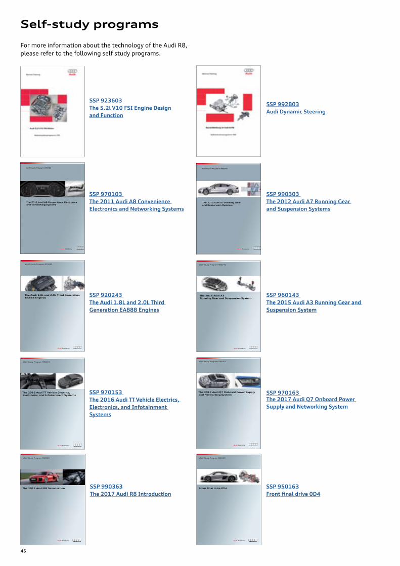
For more information about the technology of the Audi R8, please refer to the following self study programs.
SSP 923603The 5.2l V10 FSI Engine Design and Function
SSP 992803Audi Dynamic Steering
SSP 970103 The 2011 Audi A8 Convenience Electronics and Networking Systems
SSP 990303 The 2012 Audi A7 Running Gear and Suspension Systems
SSP 920243 The Audi 1.8L and 2.0L Third Generation EA888 Engines
SSP 960143 The 2015 Audi A3 Running Gear and Suspension System
SSP 970153 The 2016 Audi TT Vehicle Electrics, Electronics, and Infotainment Systems
SSP 970163 The 2017 Audi Q7 Onboard Power Supply and Networking System
i
The 2017 Audi R8 Introduction
eSelf Study Program 990363
i
Front final drive 0D4
eSelf Study Program 950163
SSP 990363The 2017 Audi R8 Introduction
SSP 950163Frontfinaldrive0D4
Self-study programs
46
From the accessaudi.com Homepage:
› Click on the “ACADEMY” tab
› Click on the “Academy site” link
› Click on the Course Catalog Search and select “970173 - The 2017 Audi R8 Electrics, Electronics,
and Infotainment Systems”
Please submit any questions or inquiries via the Academy CRC Online Support Form
which is located under the “Support” tab or the “Contact Us” tab of the Academy CRC.
Thank you for reading this eSelf-Study Program and taking the assessment.
The Knowledge Assessment is required for Certification credit.
You can find this Knowledge Assessment at:www.accessaudi.com
An On-Line Knowledge Assessment (exam) is Available for this eSelf-Study Program.
Knowledge assessment

47
All rights reserved.Technical specifications are subject to change without notice.
Audi of America, LLC2200 Ferdinand Porsche DriveHerndon, VA 20171
97
01
73