Embed Size (px)
Citation preview
Safety Precautions
i
Thank you for purchasing iG5A Series DeviceNet Communication Module
SAFETY PRECAUTIONS
Always follow safety instructions to prevent accidents and potential hazards from occurring.
Safety precautions are classified into “WARNING” and “CAUTION” and their meanings are as follows:
WARNING Improper operation may result in serious personal injury or
death.
CAUTION Improper operation may result in slight to medium personal injury or property damage
The indicated illustrations on the product and in the manual have the following meanings.
Danger may be present. Read the message and follow the instructions carefully.
Particular attention should be paid because danger of an electric shock may be present.
Keep operating instructions handy for quick reference. Read the operating instructions carefully to fully understand the functions of
the SV-iG5A series and to use it properly.
CAUTION
Be cautious, when handling the CMOS components of the communication module. Static may lead to malfunctioning of the product.
Turn off the inverter power, when changing the communication cable. Otherwise, you may damage the module or a communication error may occur.
Make sure to insert the Communication module connector to the inverter precisely. Otherwise, you may damage the module or a communication error may occur.
Check the parameter unit before setting up the parameter. Otherwise, a communication error may occur.

Table of Contents
ii
Table of Contents Chapter 1 Introduction - - - - E1 – 1Chapter 2 DeviceNet communication module specification - - - - E2 – 1Chapter 3 Communication Cable Specification - - - - E3 – 1Chapter 4 Installation - - - - E4 – 1
4.1 The Contents - - - - E4 – 14.2 Layout of DeviceNet communication module - - - - E4 – 14.3 DeviceNet communication terminal specification - - - - E4 – 14.4 Control terminal specification - - - - E4 – 24.5 Installation of DeviceNet communication module - - - - E4 – 34.6 Instruction for installation - - - - E4 – 4
Chapter 5 LED Display - - - - E5 – 15.1 NS LED Status - - - - E5 – 15.2 MS LED Status - - - - E5 – 25.3 LED Tip - - - - E5 – 3
5.3.1 In the event that Reset occurs - - - - E5 – 35.3.2 In the event of EMC by Scanner (Master) - - - - E5 – 3
Chapter 6 EDS(Electronic Data Sheets) File - - - - E6 – 1Chapter 7 Keypad Parameter associated with DeviceNet - - - - E7 – 1
7.1 Fieldbus ID (C3) - - - - E7 – 3 7.2 Fieldbus Baudrate (C4) - - - - E7 – 37.3 Fieldbus LED (C5) - - - - E7 – 47.4 In Instance, Out Instance (C29, C49) - - - - E7 – 4
Chapter 8 Definition of Object Map - - - - E8 – 18.1 Class 0x01 (Identity Object) Instance 1 - - - - E8 – 2
8.1.1 Attribute - - - - E8 – 28.1.2 Service - - - - E8 – 2
8.2 Class 0x03 (DeviceNet Object) Instance 1 - - - - E8 – 38.2.1 Attribute - - - - E8 – 38.2.2 Service - - - - E8 – 3
8.3 Class 0x04 (Assembly Object) - - - - E8 – 48.3.1 In Instance 70/110 - - - - E8 – 48.3.2 In Instance 71/111 - - - - E8 – 48.3.3 In Instance 141/142/143/144 - - - - E8 – 7
Table of Contents
iii
8.3.4 Out Instance 20/100 - - - - E8 – 7 8.3.5 Out Instance 21/101 - - - - E8 – 8 8.3.6 Out Instance 121/122/123/124 - - - - E8 – 10
8.4 Class 0x05 (DeviceNet Connection Object) - - - - E8 – 11 8.4.1 Instance - - - - E8 – 11 8.4.2 Attribute - - - - E8 – 11 8.4.3 Service - - - - E8 – 11
8.5 Class 0x28 (Motor Data Object) Instance 1 - - - - E8 – 12 8.5.1 Attribute - - - - E8 – 12 8.5.2 Service - - - - E8 – 12
8.6 Class 0x29 (Control Supervisor Object) Instance 1 - - - - E8 – 13 8.6.1 Attribute - - - - E8 – 15 8.6.2 Service - - - - E8 – 15
8.7 Class 0x2A (AC Drive Object) Instance 1 - - - - E8 – 16 8.7.1 Attribute - - - - E8 – 16 8.7.2 Service - - - - E8 – 17
8.8 Class 0x64 (Inverter Object) – Manufacture Profile - - - - E8 – 17 8.8.1 Attribute - - - - E8 – 17 8.8.2 Service - - - - E8 – 17
Chapter1. Introduction
E1-1
Chapter1. Introduction iG5A DeviceNet communication module connects the iG5A inverter with the DeviceNet network. DeviceNet communication module enables the control and monitoring of inverter to be controlled by sequence program of PLC or Master module selected optionally. As one or more inverters are connected and operated with a communication line, it reduces the installation cost compared with when communication is not used. Furthermore, simple wiring enables to the reduction of installation period and easy maintenance as well. A variety of peripheral devices such as PLC, etc. can be used to control the inverter, and factory automation is made easily by its advantage of the fact that it can be operated linked with a variety of systems such as PC, etc.
Chapter2. DeviceNet Communication Module Specification
E2-1
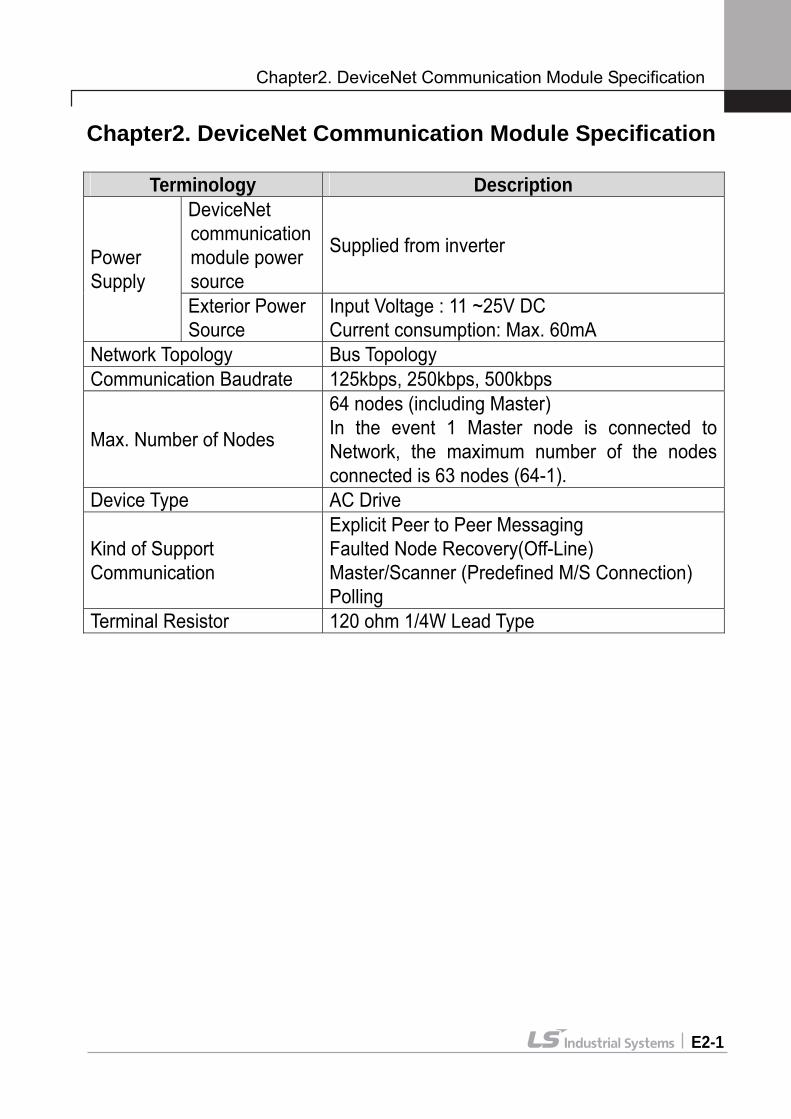
Chapter2. DeviceNet Communication Module Specification
Terminology Description DeviceNet communication module power source
Supplied from inverter Power Supply
Exterior Power Source
Input Voltage : 11 ~25V DC Current consumption: Max. 60mA
Network Topology Bus Topology Communication Baudrate 125kbps, 250kbps, 500kbps
Max. Number of Nodes
64 nodes (including Master) In the event 1 Master node is connected to Network, the maximum number of the nodes connected is 63 nodes (64-1).
Device Type AC Drive
Kind of Support Communication
Explicit Peer to Peer Messaging Faulted Node Recovery(Off-Line) Master/Scanner (Predefined M/S Connection) Polling
Terminal Resistor 120 ohm 1/4W Lead Type
Chapter3. Communication Cable Specification
E3-1
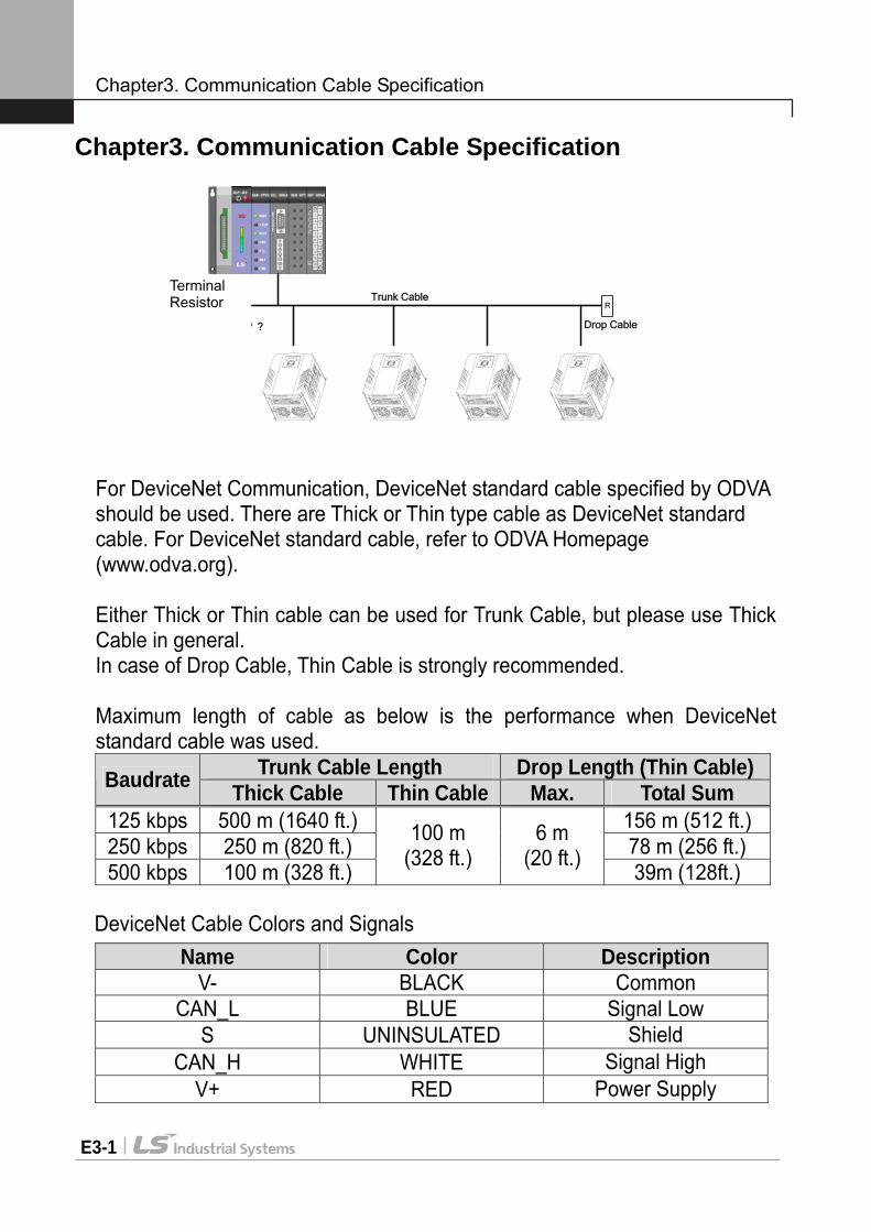
Chapter3. Communication Cable Specification
For DeviceNet Communication, DeviceNet standard cable specified by ODVA should be used. There are Thick or Thin type cable as DeviceNet standard cable. For DeviceNet standard cable, refer to ODVA Homepage (www.odva.org). Either Thick or Thin cable can be used for Trunk Cable, but please use Thick Cable in general. In case of Drop Cable, Thin Cable is strongly recommended. Maximum length of cable as below is the performance when DeviceNet standard cable was used.
Trunk Cable Length Drop Length (Thin Cable) Baudrate Thick Cable Thin Cable Max. Total Sum 125 kbps 500 m (1640 ft.) 156 m (512 ft.) 250 kbps 250 m (820 ft.) 78 m (256 ft.) 500 kbps 100 m (328 ft.)
100 m (328 ft.)
6 m (20 ft.) 39m (128ft.)
DeviceNet Cable Colors and Signals
Name Color Description V- BLACK Common
CAN_L BLUE Signal Low S UNINSULATED Shield
CAN_H WHITE Signal High V+ RED Power Supply
Trunk Cable
Drop Cable
R R
? ? ? ?
Terminal Resistor
Chapter4. Installation
E4-1
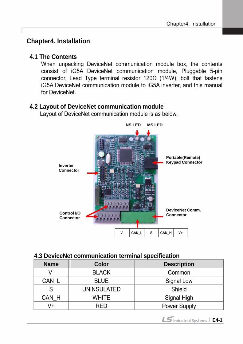
Chapter4. Installation 4.1 The Contents
When unpacking DeviceNet communication module box, the contents consist of iG5A DeviceNet communication module, Pluggable 5-pin connector, Lead Type terminal resistor 120Ω (1/4W), bolt that fastens iG5A DeviceNet communication module to iG5A inverter, and this manual for DeviceNet.
4.2 Layout of DeviceNet communication module
Layout of DeviceNet communication module is as below.
V- CAN_L S CAN_H V+
4.3 DeviceNet communication terminal specification
Name Color Description V- BLACK Common
CAN_L BLUE Signal Low S UNINSULATED Shield
CAN_H WHITE Signal High V+ RED Power Supply
NS LED MS LED
Inverter Connector
DeviceNet Comm. Connector Control I/O
Connector
Portable(Remote) Keypad Connector

Chapter4. Installation
E4-2
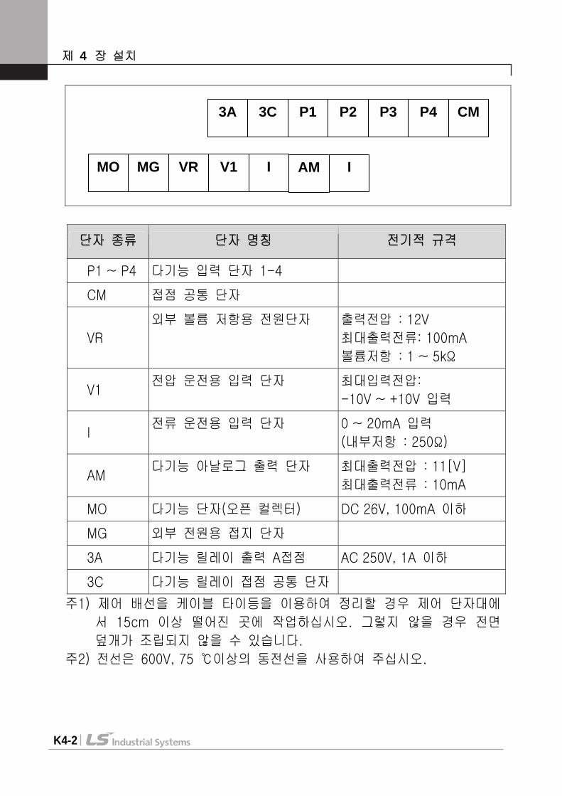
4.4 Control terminal specification
Terminal Terminal Description Specification
P1 ~ P4 Multi-function input T/M 1-4 CM Common Terminal
VR Power supply for external potentiometer
Output voltage : 12V Max output current : 10mA Potentiometer : 1 ~ 5kohm
V1 Input terminal for Voltage operation
Max input voltage : -10V ~ +10V input
I Input terminal for Current operation
0 ~ 20mA input Internal resistor : 250 ohm
AM Multi-function analog output terminal
Max output voltage : 11[V] Max output current : 10mA
MO Multi-function terminal for open collector Below DC 26V,100mA
MG Ground terminal for external power supply
3A Multi-function relay output A contact Below AC 250V, 1A
3C Common for Multi-function relays
Note 1) Tie the control wires more than 15cm away from the control terminals. Otherwise, it interferes front cover reinstallation.
Note 2) Use Copper wires rated 600V, 75 and higher.
MO MG VR V1 CM I
3A 3C P1 P2 P3 P4 CM
AM
Chapter4. Installation
E4-3
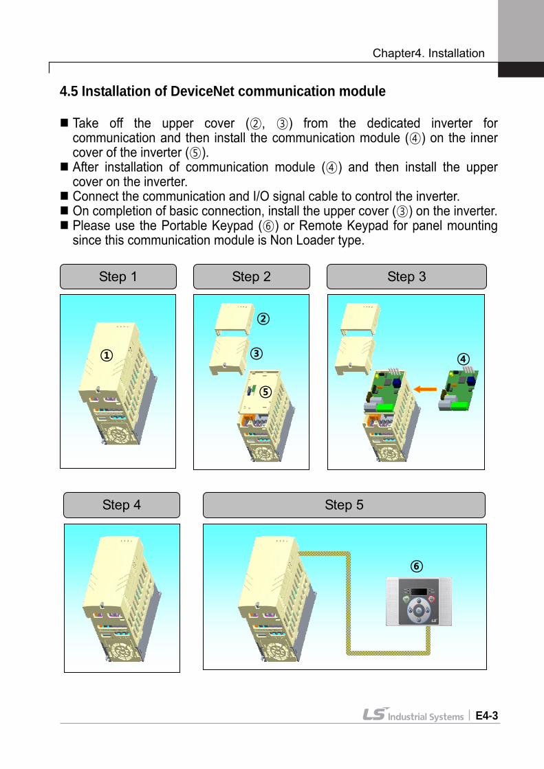
4.5 Installation of DeviceNet communication module
Take off the upper cover (②, ③) from the dedicated inverter for communication and then install the communication module (④) on the inner cover of the inverter (⑤).
After installation of communication module (④) and then install the upper cover on the inverter.
Connect the communication and I/O signal cable to control the inverter. On completion of basic connection, install the upper cover (③) on the inverter. Please use the Portable Keypad (⑥) or Remote Keypad for panel mounting since this communication module is Non Loader type.
Step 1 Step 2 Step 3
②
③ ④
⑤
①
Step 4
Step 5
⑥
Chapter4. Installation
E4-4
4.6 Instruction for installation
Don’t install or remove DeviceNet communication module with the power on. It may cause damages to both DeviceNet communication module and inverter. Be sure to install or remove DeviceNet communication module after the current of Inverter condenser has been completely discharged.
Don’t change the connection of communication signal line with the power of inverter on.
Be sure to connect the inverter body and Communication module connector exactly corresponded with each other.
In the event of connecting Communication power source (24P, 24G), be sure to check they are V-(24G), V+(24P) Silk of DeviceNet communication module before connecting them.
When configuring the Network, be sure to connect the terminal resistor to the device that is connected with the far end part. Terminal resistor should be connected between CAN_L and CAN_H. The value of terminal resistor is 120 ohm 1/4W.
Dedicated iG5A inverter for communication must be used to use iG5A DeviceNet communication option module.
The software for iG5A is supported from version 2.3. (The version of software can be checked through the parameter H79 of FUN2 group)
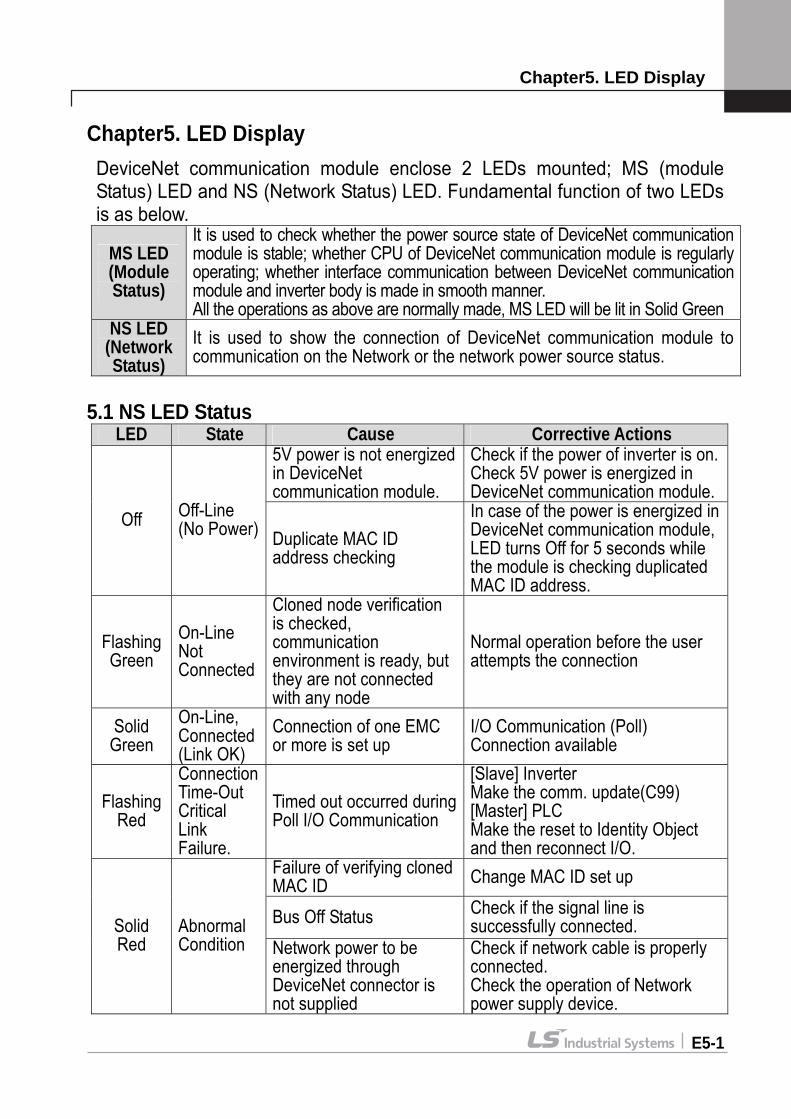
Chapter5. LED Display
E5-1
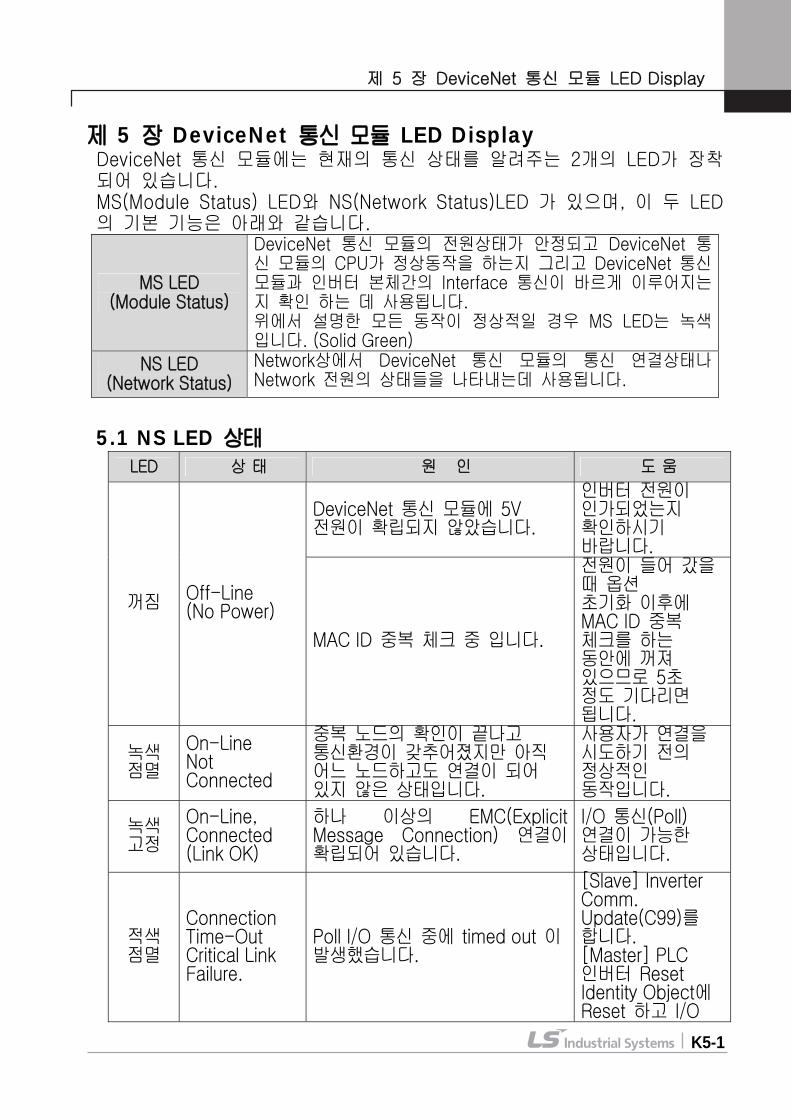
Chapter5. LED Display DeviceNet communication module enclose 2 LEDs mounted; MS (module Status) LED and NS (Network Status) LED. Fundamental function of two LEDs is as below.
MS LED (Module Status)
It is used to check whether the power source state of DeviceNet communication module is stable; whether CPU of DeviceNet communication module is regularly operating; whether interface communication between DeviceNet communication module and inverter body is made in smooth manner. All the operations as above are normally made, MS LED will be lit in Solid Green
NS LED (Network Status)
It is used to show the connection of DeviceNet communication module to communication on the Network or the network power source status.
5.1 NS LED Status
LED State Cause Corrective Actions 5V power is not energized in DeviceNet communication module.
Check if the power of inverter is on. Check 5V power is energized in DeviceNet communication module.
Off Off-Line (No Power) Duplicate MAC ID
address checking
In case of the power is energized in DeviceNet communication module, LED turns Off for 5 seconds while the module is checking duplicated MAC ID address.
Flashing Green
On-Line Not Connected
Cloned node verification is checked, communication environment is ready, but they are not connected with any node
Normal operation before the user attempts the connection
Solid Green
On-Line, Connected (Link OK)
Connection of one EMC or more is set up
I/O Communication (Poll) Connection available
Flashing Red
Connection Time-Out Critical Link Failure.
Timed out occurred during Poll I/O Communication
[Slave] Inverter Make the comm. update(C99) [Master] PLC Make the reset to Identity Object and then reconnect I/O.
Failure of verifying cloned MAC ID Change MAC ID set up
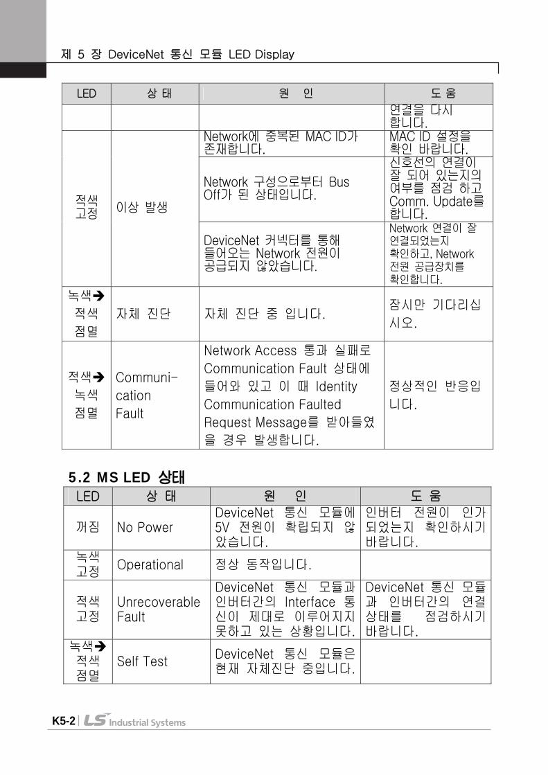
Bus Off Status Check if the signal line is successfully connected. Solid
Red Abnormal Condition Network power to be
energized through DeviceNet connector is not supplied
Check if network cable is properly connected. Check the operation of Network power supply device.
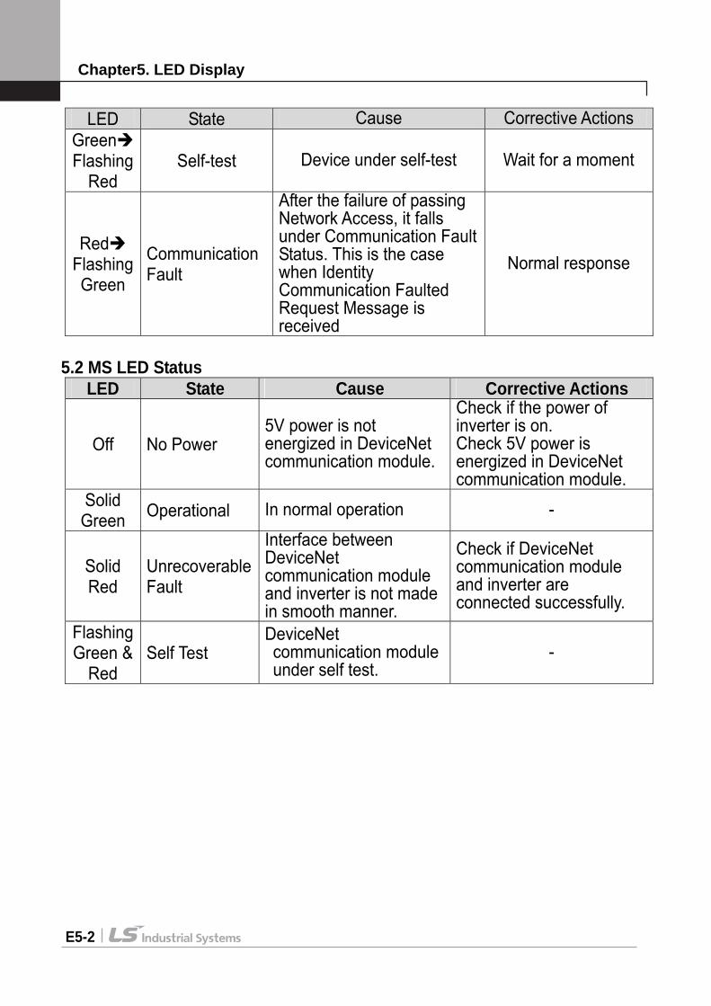
Chapter5. LED Display
E5-2
LED State Cause Corrective Actions Green Flashing
Red Self-test Device under self-test Wait for a moment
Red Flashing Green
Communication Fault
After the failure of passing Network Access, it falls under Communication Fault Status. This is the case when Identity Communication Faulted Request Message is received
Normal response
5.2 MS LED Status
LED State Cause Corrective Actions
Off No Power 5V power is not energized in DeviceNet communication module.
Check if the power of inverter is on. Check 5V power is energized in DeviceNet communication module.
Solid Green Operational In normal operation -
Solid Red
Unrecoverable Fault
Interface between DeviceNet communication module and inverter is not made in smooth manner.
Check if DeviceNet communication module and inverter are connected successfully.
Flashing Green &
Red Self Test
DeviceNet communication module under self test.
-

Chapter5. LED Display
E5-3
5.3 LED Tip 5.3.1 In the event that Reset occurs
MS (module Status) LED glows in Green-Red at every 0.5 second at the beginning, but when the Interface communication between DeviceNet communication module and inverter comes to normal state, it becomes solid Green.
Then, NS (Network Status) LED flashes in Green-Red at every 0.5 second. In the event there is no abnormality as result of checking the redundant MAC ID, Network Status LED flashes in Green. It means this Device communication module is connected to the Network in normal way, but communication is not made with any Device.
If it fails to run as above, please check any of the following three cases. If it runs in normal way, you may disregard the following cases.
If the interface communication between DeviceNet communication module and inverter doesn’t run in normal way, MS (module Status) LED becomes solid Red. In this case, be sure to check the connection between inverter and DeviceNet communication module first, and then turn on the Inverter.
In the event that NS doesn’t flash in Green just keeping Off state, it falls under the case either Network power is not on or the Baudrates of current network and Communication module are not matched. You need to check this point carefully.
In the event there is abnormality as result of checking the redundant MAC ID, Network Status LED becomes solid Red. In this case, please configure MAC ID at the other value using Keypad.
In the event that the Communication module is in communication with the other Device, NS (Network Status) LED becomes solid Green.
5.3.2 In the event of EMC (Explicit Message Connection) by Scanner
(Master) Network Status LED becomes solid Green If EMC setting is released here, it flashes in Green again after 10 seconds. Once EMC is achieved, I/O Connection is available. In this case, the Network Status LED is still continued.
In the event that no communication is made within the time I/O Connection is set, Time Out occurs, and then Network Status LED flashes in Red. (This Status can be changed into flashing Green again depending on the time setting of EMC.

Chapter6. EDS File
E6-1
Chapter6. EDS (Electronic Data Sheets) File This file includes the information on the parameters of inverter. It is used when the user intends to control the parameters of iG5A through the DeviceNet Manager program. In this case, it is necessary to install on PC the iG5A-use EDS file that we provide. EDS file can be downloaded at the Homepage of LSIS. EDS file name : Lsis_iG5A_AcDrive.EDS Revision : 2.01 Paste ‘Lsis_iG5A_AcDrive.EDS’ file in the folder for the EDS file via Master Configuration programming tool. Example) SyCon program for XGT Series
Paste ‘Lsis_iG5A_AcDrive.EDS’ file in subfolder ‘EDS’ of DevNet as below figure.
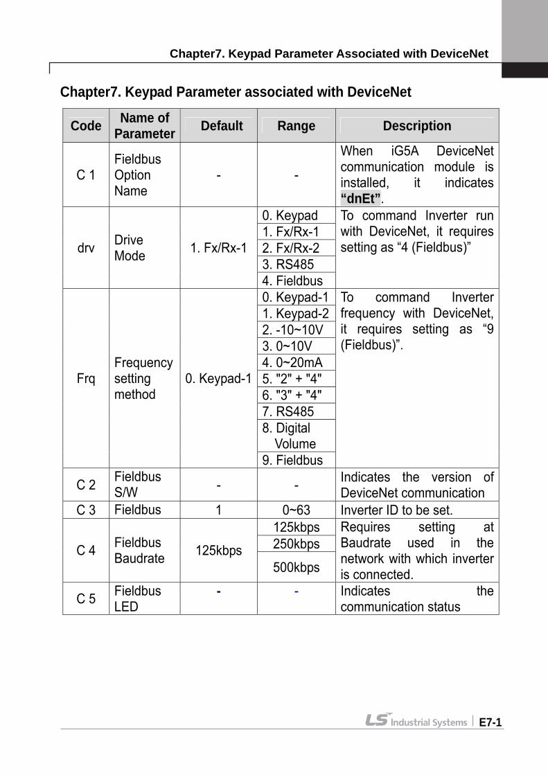
Chapter7. Keypad Parameter Associated with DeviceNet
E7-1
Chapter7. Keypad Parameter associated with DeviceNet
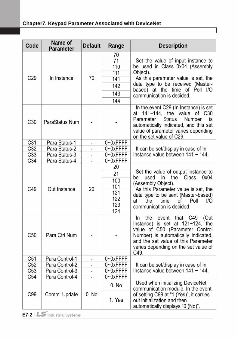
Code Name of Parameter Default Range Description
C 1 Fieldbus Option Name
- -
When iG5A DeviceNet communication module is installed, it indicates “dnEt”.
0. Keypad 1. Fx/Rx-1 2. Fx/Rx-2 3. RS485
drv Drive Mode 1. Fx/Rx-1
4. Fieldbus
To command Inverter run with DeviceNet, it requires setting as “4 (Fieldbus)”
0. Keypad-11. Keypad-22. -10~10V 3. 0~10V 4. 0~20mA 5. "2" + "4" 6. "3" + "4" 7. RS485 8. Digital Volume
Frq Frequency setting method
0. Keypad-1
9. Fieldbus
To command Inverter frequency with DeviceNet, it requires setting as “9 (Fieldbus)”.
C 2 Fieldbus S/W - - Indicates the version of
DeviceNet communication C 3 Fieldbus 1 0~63 Inverter ID to be set.
125kbps 250kbps C 4 Fieldbus
Baudrate 125kbps 500kbps
Requires setting at Baudrate used in the network with which inverter is connected.
C 5 Fieldbus LED
- - Indicates the communication status
Chapter7. Keypad Parameter Associated with DeviceNet
E7-2
Code Name of Parameter Default Range Description
70 71 110 111 141 142 143
C29 In Instance 70
144
Set the value of input instance to be used in Class 0x04 (Assembly Object). As this parameter value is set, the
data type to be received (Master-based) at the time of Poll I/O communication is decided.
C30 ParaStatus Num - -
In the event C29 (In Instance) is set at 141~144, the value of C30 Parameter Status Number is automatically indicated, and this set value of parameter varies depending on the set value of C29.
C31 Para Status-1 - 0~0xFFFFC32 Para Status-2 - 0~0xFFFFC33 Para Status-3 - 0~0xFFFFC34 Para Status-4 - 0~0xFFFF
It can be set/display in case of In Instance value between 141 ~ 144.
20 21 100 101 121 122 123
C49 Out Instance 20
124
Set the value of output instance to be used in the Class 0x04 (Assembly Object). As this Parameter value is set, the
data type to be sent (Master-based) at the time of Poll I/O communication is decided.
C50 Para Ctrl Num - -
In the event that C49 (Out Instance) is set at 121~124, the value of C50 (Parameter Control Number) is automatically indicated, and the set value of this Parameter varies depending on the set value of C49.
C51 Para Control-1 - 0~0xFFFFC52 Para Control-2 - 0~0xFFFFC53 Para Control-3 - 0~0xFFFFC54 Para Control-4 - 0~0xFFFF
It can be set/display in case of In Instance value between 141 ~ 144.
0. No C99 Comm. Update 0. No
1. Yes
Used when initializing DeviceNet communication module. In the event of setting C99 at “1 (Yes)”, it carries out initialization and then automatically displays “0 (No)”.
Chapter7. Keypad Parameter Associated with DeviceNet
E7-5
※ Run and Frequency command through DeviceNet have to set to Fieldbus of drv (Run command method) mode and Frq (Frequency command method) mode.
7.1 Fieldbus ID (C3)
Fieldbus ID falls under MAC ID (Media Access Control Identifier) that is called in DeviceNet.
As this value is an indigenous value by which each Device is discriminated in DeviceNet Network, it is not allowed for different Devices to have same values.
This value is preset as 1 at the factory. In the event that interface communication is in trouble between DeviceNet communication module and inverter, Default value is automatically changed into “63”.
In the event of modifying MAC ID during operation, DeviceNet communication module will be automatically reset. This is because it is essential to check if Device using MAC ID value newly set is on the Network.
In the event the preset MAC ID value is the one that has already been used by the other Device, NS (Network Status) LED will be changed to solid Red. Here, MAC ID can be changed into the other value using Keypad again. After that, if NS is flashing in green, it means its normal operation.
7.2 Fieldbus Baudrate (C4)
In the event that the communication speed set is not same as that used in the Network, NS LED maintains Off state.
In the event changing the Baudrate using Keypad, in order for the changed Baudrate value to influence the actual communication speed, it is necessary to send Reset Service to the Identity Object of Inverter through communication or reset the Inverter.
You may reset the Inverter using C36 (Communication Update). ※ In the event that Network Baudrate corresponds with Communication
module Baudrate and MAC ID is the only one, NS LED flashes in Green.
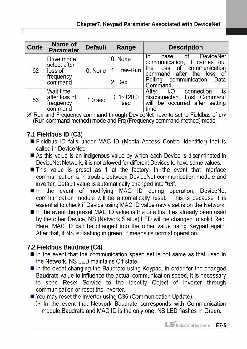
Code Name of Parameter Default Range Description
0. None
1. Free-RunI62
Drive mode select after loss of frequency command
0. None
2. Dec
In case of DeviceNet communication, it carries out the loss of communication command after the loss of Polling communication Data Command.
I63 Wait time after loss of frequency command
1.0 sec 0.1~120.0 sec
After I/O connection is disconnected, Lost Command will be occurred after setting time.

Chapter8. Definition of Object Map
E8-1
7.3 Fieldbus LED (C5) DeviceNet communication module has MS LED and NS LED only, but four LEDs are shown from C5 (Fieldbus LED Status) using Keypad. It displays the information of NS LED Red, NS LED Green, MS LED Red and MS LED Green in the order of C5 LEDs (Left Right). If C5 is displayed as below, it indicates that currently NS LED is Green and MS LED is Green. Example of C5 LED status
7.4 In Instance, Out Instance (C29, C49)
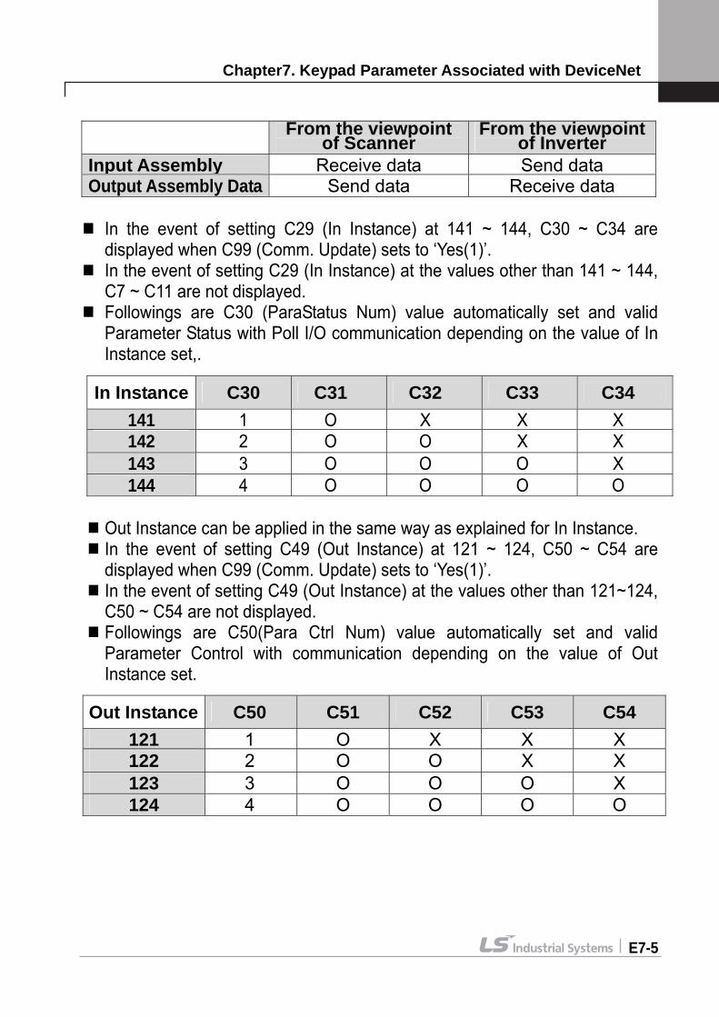
In Instance, Out Instance is used in the Poll I/O Data Communication. Poll I/O Connection is the Connection to communicate specific data between Scanner (Master) and Inverter.
Type of data sent through Poll I/O is decided by the Assembly Instances (C29, C49).
In case of Instance 20, 21, 100, 101, 70, 71, 110 and 111, the amount of data sent by Poll I/O Communication is 4 Bytes in both directions, and the communication cycle default value is 0 (zero). Assembly Instance can be broadly divided into Output and Input based on Scanner. That is, Input Data means the amount of data stored in Scanner. It means the value for inverter to feed back to Scanner. On the contrary, Output Data means the amount of data supplied from Scanner, which is a new command value for Inverter. In the event of changing the value of In Instance or Out Instance, DeviceNet communication module is automatically reset.
NS LED Red NS LED Green MS LED Red MS LED Green OFF ON OFF ON
NS LED MS LED Red Green Red Green
(ON)
(OFF)
Scanner (Master)
iG5A Inverter
Output Assembly
Input Assembly
Chapter7. Keypad Parameter Associated with DeviceNet
E7-5
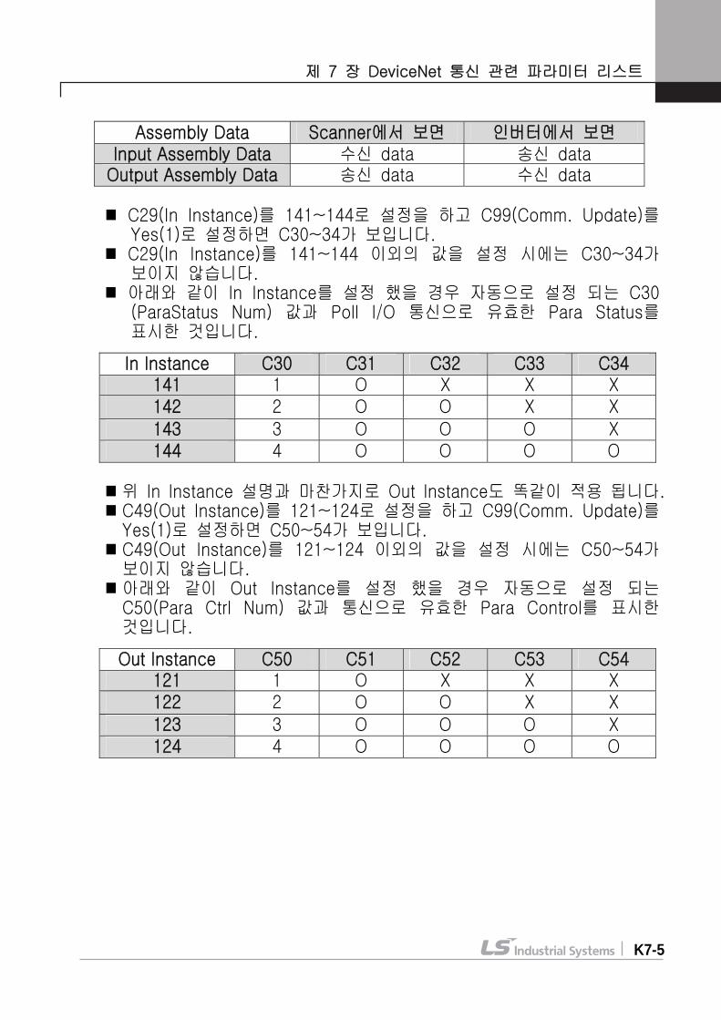
In the event of setting C29 (In Instance) at 141 ~ 144, C30 ~ C34 are
displayed when C99 (Comm. Update) sets to ‘Yes(1)’. In the event of setting C29 (In Instance) at the values other than 141 ~ 144,
C7 ~ C11 are not displayed. Followings are C30 (ParaStatus Num) value automatically set and valid
Parameter Status with Poll I/O communication depending on the value of In Instance set,.
Out Instance can be applied in the same way as explained for In Instance. In the event of setting C49 (Out Instance) at 121 ~ 124, C50 ~ C54 are displayed when C99 (Comm. Update) sets to ‘Yes(1)’.
In the event of setting C49 (Out Instance) at the values other than 121~124, C50 ~ C54 are not displayed.
Followings are C50(Para Ctrl Num) value automatically set and valid Parameter Control with communication depending on the value of Out Instance set.
From the viewpoint of Scanner
From the viewpoint of Inverter
Input Assembly Receive data Send dataOutput Assembly Data Send data Receive data
In Instance C30 C31 C32 C33 C34 141 1 O X X X142 2 O O X X 143 3 O O O X 144 4 O O O O
Out Instance C50 C51 C52 C53 C54 121 1 O X X X122 2 O O X X 123 3 O O O X 124 4 O O O O
Chapter8. Definition of Object Map
E8-1
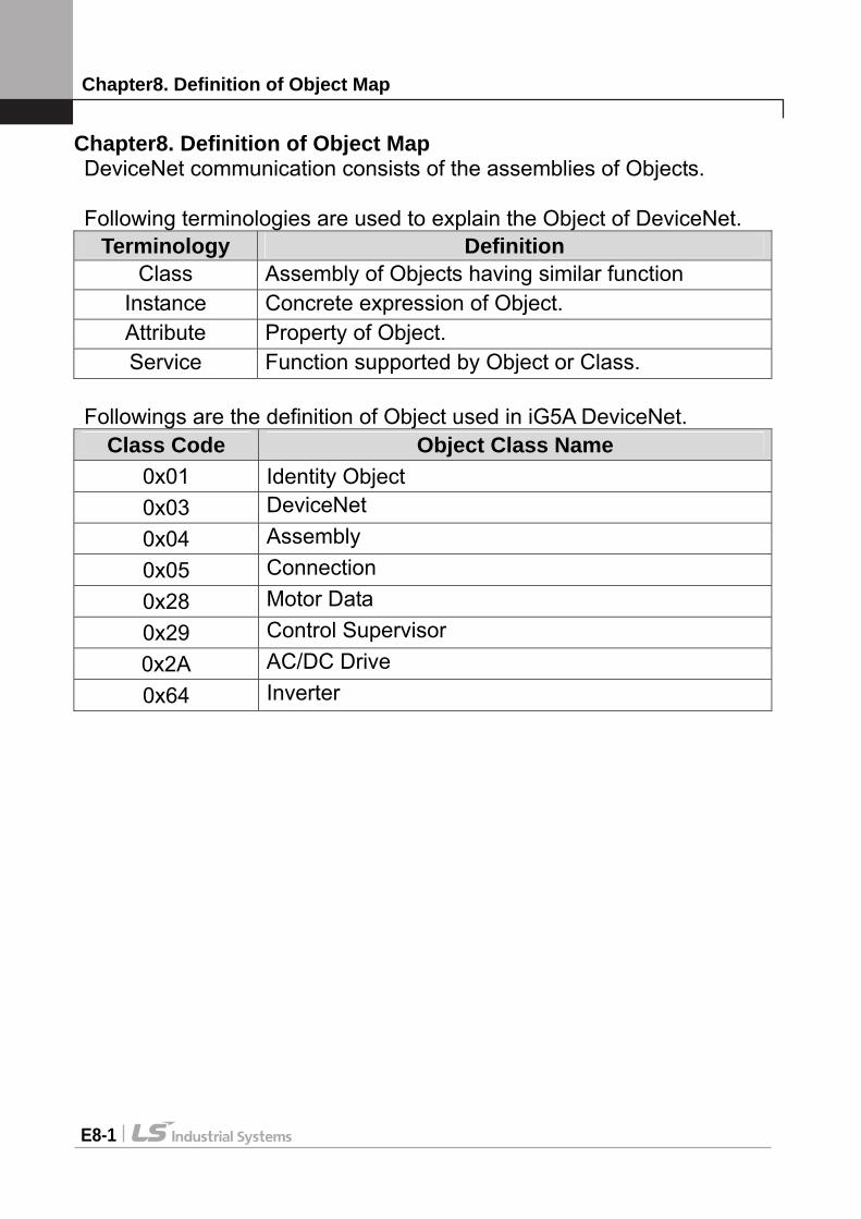
Chapter8. Definition of Object Map DeviceNet communication consists of the assemblies of Objects. Following terminologies are used to explain the Object of DeviceNet.
Terminology Definition Class Assembly of Objects having similar function
Instance Concrete expression of Object. Attribute Property of Object. Service Function supported by Object or Class.
Followings are the definition of Object used in iG5A DeviceNet.
Class Code Object Class Name 0x01 Identity Object 0x03 DeviceNet 0x04 Assembly 0x05 Connection 0x28 Motor Data 0x29 Control Supervisor 0x2A AC/DC Drive 0x64 Inverter

Chapter8. Definition of Object Map
E8-2
8.1 Class 0x01 (Identity Object) Instance 1 (Entire device, host and adapter) 8.1.1 Attribute
Attribute ID Access Attribute Name Data
Length Attribute
Value
1 Get Vendor ID (LS Industrial Systems) Word 259
2 Get Device Type (AC Drive) Word 2 3 Get Product Code Word 10 (Note1)
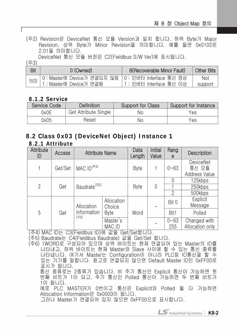
4 Get Revision Low Byte - Major Revision High Byte - Minor Revision
Word (Note 2)
5 Get Status Word (Note 3)
6 Get Serial Number Double Word -
7 Get Product Name 14 Byte iG5A DeviceNet
(Note 1) Product Code 10 means iG5A inverter (Note 2) Revision corresponds with the version of DeviceNet communication
module. High Byte means Major Revision, and Low Byte means Minor Revision. For example, 0x0102 means 2.01. DeviceNet communication module version is displayed in C2 (Fieldbus S/W Version)
(Note 3)
Bit 0 (Owned) 8 (Recoverable Minor Fault) Other Bits
Meaning
0 : Device is not connected to Master
1 : Device is connected to Master
0 : inverter Interface communication is in normal state
1 : inverter Interface communication is in abnormal state
Not support
8.1.2 Service
Service Code Definition Support for Class Support for
Instance 0x0E Get Attribute Single No Yes 0x05 Reset No Yes
Chapter8. Definition of Object Map
E8-3
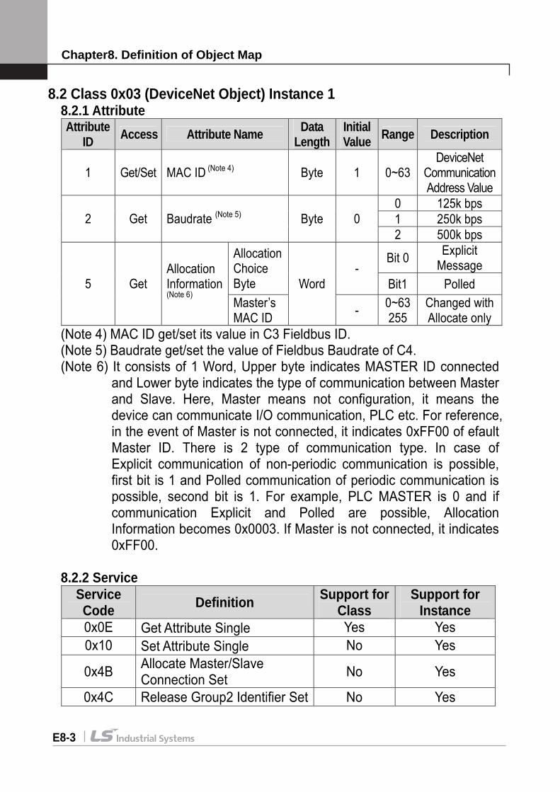
8.2 Class 0x03 (DeviceNet Object) Instance 1 8.2.1 Attribute
Attribute ID Access Attribute Name Data
LengthInitial Value Range Description
1 Get/Set MAC ID (Note 4) Byte 1 0~63 DeviceNet
Communication Address Value
0 125k bps 1 250k bps 2 Get Baudrate (Note 5) Byte 0 2 500k bps
Bit 0 Explicit Message
Allocation Choice Byte
- Bit1 Polled 5 Get
Allocation Information (Note 6)
Master’s MAC ID
Word
- 0~63 255
Changed with Allocate only
(Note 4) MAC ID get/set its value in C3 Fieldbus ID. (Note 5) Baudrate get/set the value of Fieldbus Baudrate of C4.
(Note 6) It consists of 1 Word, Upper byte indicates MASTER ID connected and Lower byte indicates the type of communication between Master and Slave. Here, Master means not configuration, it means the device can communicate I/O communication, PLC etc. For reference, in the event of Master is not connected, it indicates 0xFF00 of efault Master ID. There is 2 type of communication type. In case of Explicit communication of non-periodic communication is possible, first bit is 1 and Polled communication of periodic communication is possible, second bit is 1. For example, PLC MASTER is 0 and if communication Explicit and Polled are possible, Allocation Information becomes 0x0003. If Master is not connected, it indicates 0xFF00.
8.2.2 Service
Service Code Definition Support for
Class Support for
Instance 0x0E Get Attribute Single Yes Yes 0x10 Set Attribute Single No Yes
0x4B Allocate Master/Slave Connection Set No Yes
0x4C Release Group2 Identifier Set No Yes

Chapter8. Definition of Object Map
E8-4
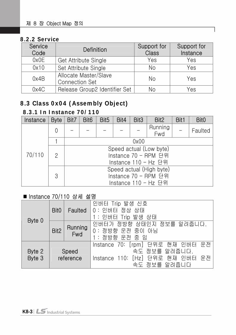
8.3 Class 0x04 (Assembly Object) 8.3.1 In Instance 70/110
Instance Byte Bit7 Bit6 Bit5 Bit4 Bit3 Bit2 Bit1 Bit0
0 - - - - - Running Fwd - Faulted
1 0x00
2 Speed actual (Low byte)
Instance 70 - RPM Instance 110 - Hz
70/110
3 Speed actual (High byte)
Instance 70 - RPM Instance 110 - Hz
Explanation on Instance 70/110
Bit0 Faulted Signal on the occurrence of inverter Trip 0 : Inverter in normal condition 1 : Occurrence of Inverter Trip
Byte 0
Bit2 Running Fwd
Indicates the information if Inverter runs in forward direction. 0 : Not in forward direction. 1 : In forward direction
Byte 2 Byte 3
Speed reference
Instance 70 : Indicates the current information on inverter running speed in [rpm]
Instance 110 : Indicates the current information on inverter running speed in [Hz]
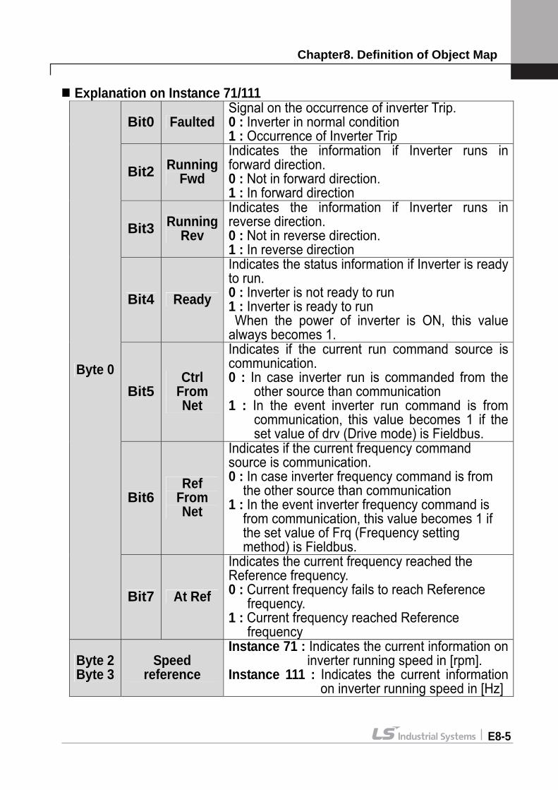
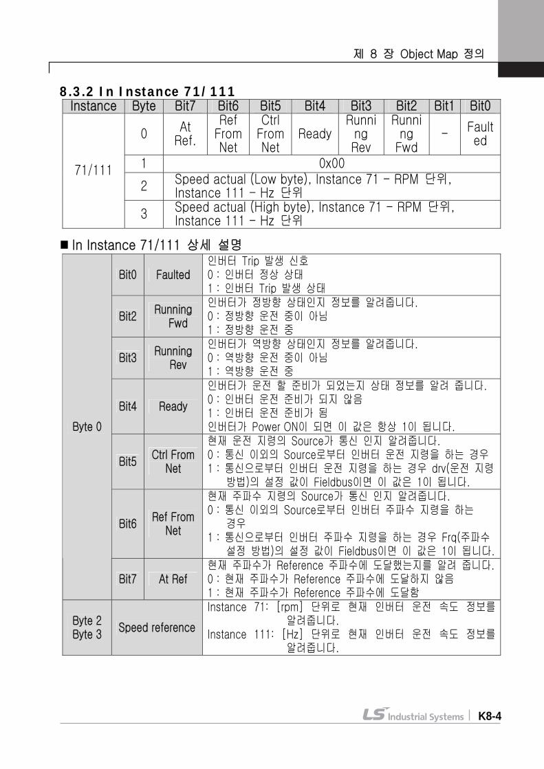
8.3.2 In Instance 71/111
Instance Byte Bit7 Bit6 Bit5 Bit4 Bit3 Bit2 Bit1 Bit0
0 At Ref.
Ref From Net
Ctrl From Net
ReadyRunn-
ing Rev
Runn-ing Fwd
- Faulted
1 0x00
2 Speed actual (Low byte)
Instance 71 - RPM Instance 111 - Hz
71/111
3 Speed actual (High byte)
Instance 71 - RPM Instance 111 - Hz
Chapter8. Definition of Object Map
E8-5
Explanation on Instance 71/111
Bit0 Faulted Signal on the occurrence of inverter Trip. 0 : Inverter in normal condition 1 : Occurrence of Inverter Trip
Bit2 Running Fwd
Indicates the information if Inverter runs in forward direction. 0 : Not in forward direction. 1 : In forward direction
Bit3 Running Rev
Indicates the information if Inverter runs in reverse direction. 0 : Not in reverse direction. 1 : In reverse direction
Bit4 Ready
Indicates the status information if Inverter is ready to run. 0 : Inverter is not ready to run 1 : Inverter is ready to run When the power of inverter is ON, this value always becomes 1.
Bit5 Ctrl
From Net
Indicates if the current run command source is communication. 0 : In case inverter run is commanded from the
other source than communication 1 : In the event inverter run command is from
communication, this value becomes 1 if the set value of drv (Drive mode) is Fieldbus.
Bit6 Ref
From Net
Indicates if the current frequency command source is communication. 0 : In case inverter frequency command is from
the other source than communication 1 : In the event inverter frequency command is
from communication, this value becomes 1 if the set value of Frq (Frequency setting method) is Fieldbus.
Byte 0
Bit7 At Ref
Indicates the current frequency reached the Reference frequency. 0 : Current frequency fails to reach Reference
frequency. 1 : Current frequency reached Reference
frequency
Byte 2 Byte 3
Speed reference
Instance 71 : Indicates the current information on inverter running speed in [rpm].
Instance 111 : Indicates the current information on inverter running speed in [Hz]
Chapter8. Definition of Object Map
E8-6
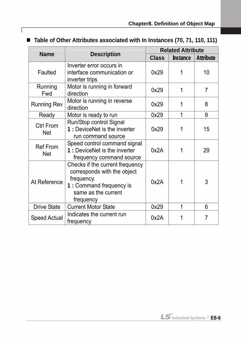
Table of Other Attributes associated with In Instances (70, 71, 110, 111)
Related Attribute Name Description Class Instance Attribute
Faulted Inverter error occurs in interface communication or inverter trips
0x29 1 10
Running Fwd
Motor is running in forward direction 0x29 1 7
Running Rev Motor is running in reverse direction 0x29 1 8
Ready Motor is ready to run 0x29 1 9
Ctrl From Net
Run/Stop control Signal 1 : DeviceNet is the inverter
run command source 0x29 1 15
Ref From Net
Speed control command signal1 : DeviceNet is the inverter
frequency command source 0x2A 1 29
At Reference
Checks if the current frequency corresponds with the object frequency.
1 : Command frequency is same as the current frequency
0x2A 1 3
Drive State Current Motor State 0x29 1 6
Speed Actual Indicates the current run frequency 0x2A 1 7
Chapter8. Definition of Object Map
E8-7
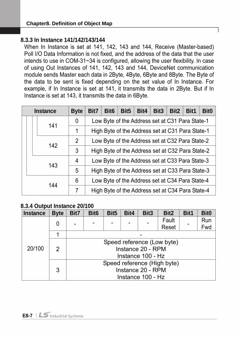
8.3.3 In Instance 141/142/143/144 When In Instance is set at 141, 142, 143 and 144, Receive (Master-based) Poll I/O Data Information is not fixed, and the address of the data that the user intends to use in COM-31~34 is configured, allowing the user flexibility. In case of using Out Instances of 141, 142, 143 and 144, DeviceNet communication module sends Master each data in 2Byte, 4Byte, 6Byte and 8Byte. The Byte of the data to be sent is fixed depending on the set value of In Instance. For example, if In Instance is set at 141, it transmits the data in 2Byte. But if In Instance is set at 143, it transmits the data in 6Byte.
Instance Byte Bit7 Bit6 Bit5 Bit4 Bit3 Bit2 Bit1 Bit00 Low Byte of the Address set at C31 Para State-1 141 1 High Byte of the Address set at C31 Para State-1 2 Low Byte of the Address set at C32 Para State-2 142 3 High Byte of the Address set at C32 Para State-2 4 Low Byte of the Address set at C33 Para State-3 143 5 High Byte of the Address set at C33 Para State-3 6 Low Byte of the Address set at C34 Para State-4 144 7 High Byte of the Address set at C34 Para State-4
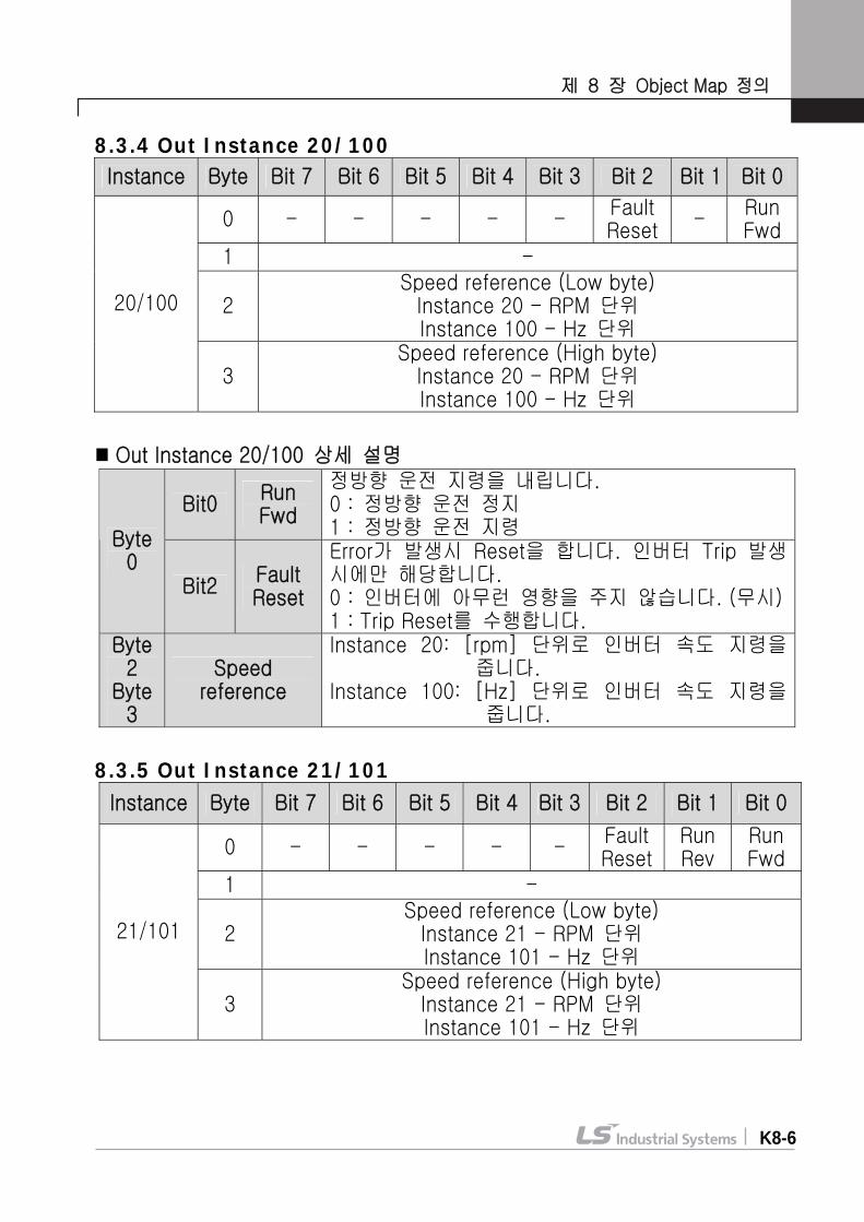
8.3.4 Output Instance 20/100 Instance Byte Bit7 Bit6 Bit5 Bit4 Bit3 Bit2 Bit1 Bit0
0 - - - - - Fault Reset - Run
Fwd 1 -
2 Speed reference (Low byte)
Instance 20 - RPM Instance 100 - Hz
20/100
3 Speed reference (High byte)
Instance 20 - RPM Instance 100 - Hz

Chapter8. Definition of Object Map
E8-9
Explanation on Instance 20/100
Bit0 Run Fwd
Forward direction run command. 0 : Stop Forward direction run 1 : Forward direction run command
Byte 0
Bit2 Fault Reset
Reset when error occurs. It happens only when inverter trip occurs. 0 : It doesn’t adversely affect the inverter. (You may not be concerned about it) 1 : performs Trip Reset.
Byte 2 Byte 3
Speed reference
Instance 20 : Commands the inverter speed in [rpm].
Instance 100 : Commands the inverter speed in [Hz].
8.3.5 Output Instance 21/101
Instance Byte Bit7 Bit6 Bit5 Bit4 Bit3 Bit2 Bit1 Bit0
0 - - - - - Fault Reset
RunRev
RunFwd
1 -
2 Speed reference (Low byte)
Instance 21 - RPM Instance 101 - Hz
21/101
3 Speed reference (High byte)
Instance 21 - RPM Instance 101 - Hz
Explanation on Instance 21/101
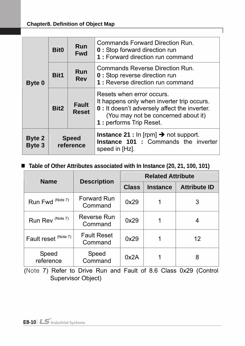
Chapter8. Definition of Object Map
E8-10
Bit0 Run Fwd
Commands Forward Direction Run. 0 : Stop forward direction run 1 : Forward direction run command
Bit1 Run Rev
Commands Reverse Direction Run. 0 : Stop reverse direction run 1 : Reverse direction run command Byte 0
Bit2 Fault Reset
Resets when error occurs. It happens only when inverter trip occurs. 0 : It doesn’t adversely affect the inverter. (You may not be concerned about it) 1 : performs Trip Reset.
Byte 2 Byte 3
Speed reference
Instance 21 : In [rpm] not support. Instance 101 : Commands the inverter speed in [Hz].
Table of Other Attributes associated with In Instance (20, 21, 100, 101)
(Note 7) Refer to Drive Run and Fault of 8.6 Class 0x29 (Control Supervisor Object)
Related Attribute Name Description
Class Instance Attribute ID
Run Fwd (Note 7) Forward Run Command 0x29 1 3
Run Rev (Note 7) Reverse Run Command 0x29 1 4
Fault reset (Note 7) Fault Reset Command 0x29 1 12
Speed reference
Speed Command 0x2A 1 8

Chapter8. Definition of Object Map
E8-10
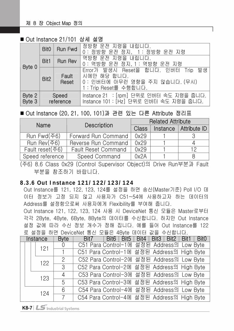
8.3.6 Out Instance 121/122/123/124 When Out Instance is set at 121, 122, 123 and 124, Send (Master-based) Poll I/O Data Information is not fixed, but the address of the data that the user intends to for C51 ~ C54 is set, giving the user flexibility.
At the time of using Out Instance 121, 122, 123 and 124, DeviceNet communication module receives from Master the data of 2Byte, 4Byte, 6Byte and 8Byte. However, the number of information received is decided depending on the set value of Out Instance. For example, if Out Instance is set at 122, the DeviceNet communication module receives the data value of 4Byte.
Instance Byte Bit7 Bit6 Bit5 Bit4 Bit3 Bit2 Bit1 Bit0
0 Low Byte of the Address set at C51 Para State-1 121 1 High Byte of the Address set at C51 Para Control1 2 Low Byte of the Address set at C52 Para Control-2 122 3 High Byte of the Address set at C52 Para Control-2 4 Low Byte of the Address set at C53 Para Control-3 123 5 High Byte of the Address set at C53 Para Control-3 6 Low Byte of the Address set at C54 Para Control-4 124 7 High Byte of the Address set at C54 Para Control-4
Chapter8. Definition of Object Map
E8-11
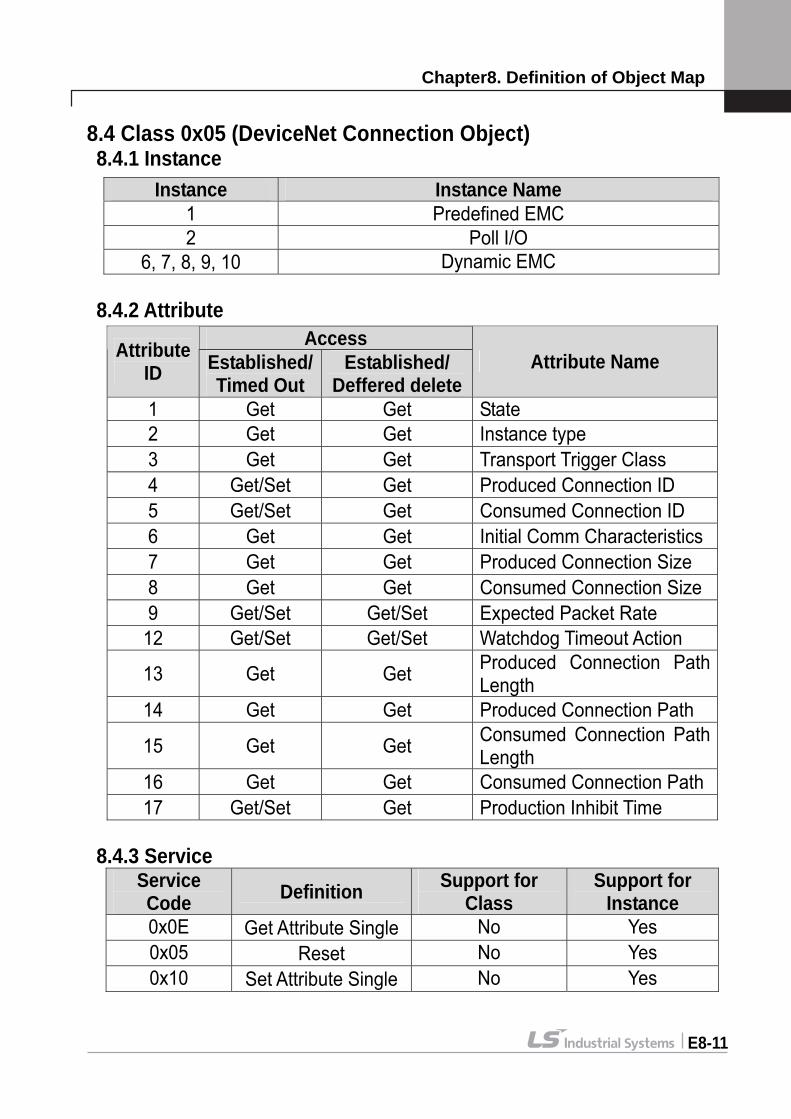
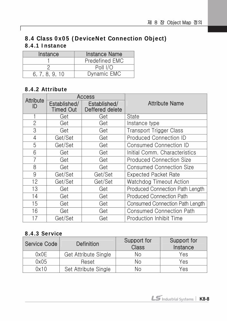
8.4 Class 0x05 (DeviceNet Connection Object) 8.4.1 Instance
8.4.2 Attribute
8.4.3 Service
Service Code Definition Support for
Class Support for
Instance 0x0E Get Attribute Single No Yes 0x05 Reset No Yes 0x10 Set Attribute Single No Yes
Instance Instance Name 1 Predefined EMC 2 Poll I/O
6, 7, 8, 9, 10 Dynamic EMC
Access Attribute ID Established/
Timed Out Established/
Deffered deleteAttribute Name
1 Get Get State 2 Get Get Instance type 3 Get Get Transport Trigger Class 4 Get/Set Get Produced Connection ID 5 Get/Set Get Consumed Connection ID 6 Get Get Initial Comm Characteristics 7 Get Get Produced Connection Size 8 Get Get Consumed Connection Size 9 Get/Set Get/Set Expected Packet Rate
12 Get/Set Get/Set Watchdog Timeout Action
13 Get Get Produced Connection Path Length
14 Get Get Produced Connection Path
15 Get Get Consumed Connection Path Length
16 Get Get Consumed Connection Path 17 Get/Set Get Production Inhibit Time
Chapter8. Definition of Object Map
E8-12
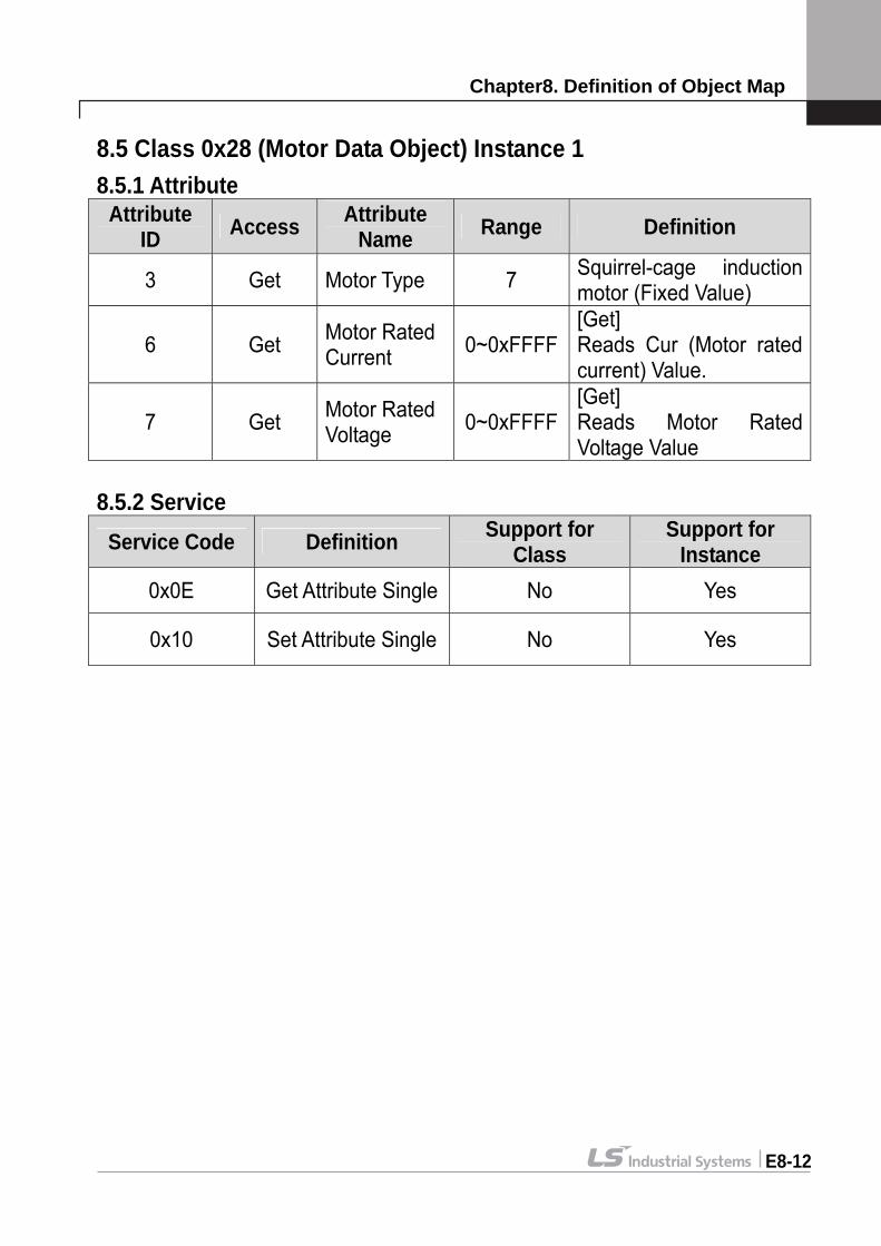
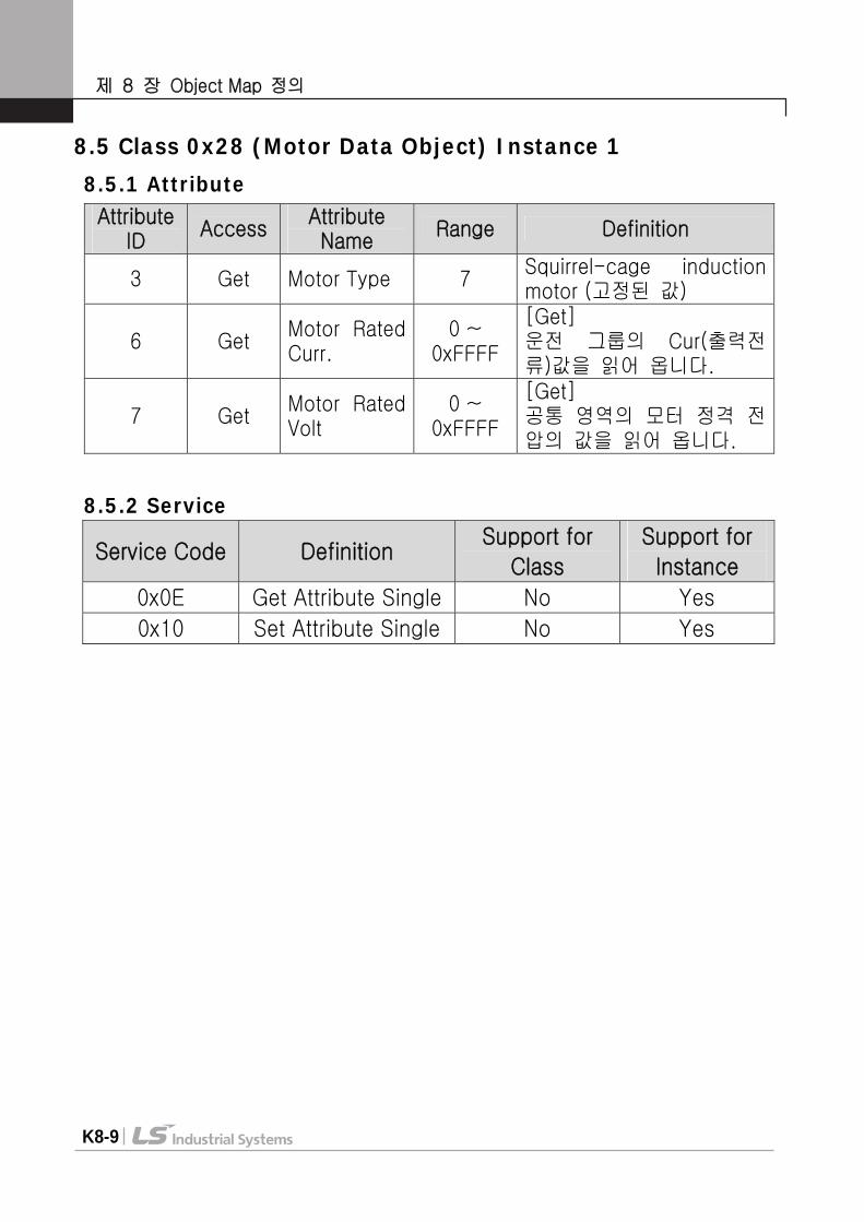
8.5 Class 0x28 (Motor Data Object) Instance 1 8.5.1 Attribute
8.5.2 Service
Service Code Definition Support for Class
Support for Instance
0x0E Get Attribute Single No Yes
0x10 Set Attribute Single No Yes
Attribute ID Access Attribute
Name Range Definition
3 Get Motor Type 7 Squirrel-cage induction motor (Fixed Value)
6 Get Motor Rated Current 0~0xFFFF
[Get] Reads Cur (Motor rated current) Value.
7 Get Motor Rated Voltage 0~0xFFFF
[Get] Reads Motor Rated Voltage Value
Chapter8. Definition of Object Map
E8-13
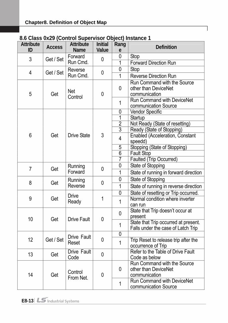
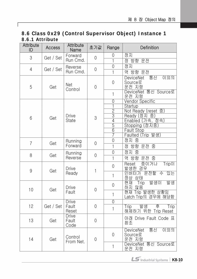
8.6 Class 0x29 (Control Supervisor Object) Instance 1
Attribute ID Access Attribute
Name Initial Value
Range Definition 0 Stop 3 Get / Set Forward
Run Cmd. 0 1 Forward Direction Run 0 Stop 4 Get / Set Reverse
Run Cmd. 0 1 Reverse Direction Run
0 Run Command with the Source other than DeviceNet communication 5 Get Net
Control 0 1 Run Command with DeviceNet
communication Source 0 Vendor Specific 1 Startup 2 Not Ready (State of resetting) 3 Ready (State of Stopping) 4 Enabled (Acceleration, Constant
speedd) 5 Stopping (State of Stopping) 6 Fault Stop
6 Get Drive State 3
7 Faulted (Trip Occurred) 0 State of Stopping 7 Get Running
Forward 0 1 State of running in forward direction0 State of Stopping 8 Get Running
Reverse 0 1 State of running in reverse direction0 State of resetting or Trip occurred.
9 Get Drive Ready 1 1 Normal condition where inverter
can run 0 State that Trip doesn’t occur at
present 10 Get Drive Fault 0 1 State that Trip occurred at present.
Falls under the case of Latch Trip 0
12 Get / Set Drive Fault Reset 0 1 Trip Reset to release trip after the
occurrence of Trip 13 Get Drive Fault
Code 0 Refer to the Table of Drive Fault Code as below
0 Run Command with the Source other than DeviceNet communication 14 Get Control
From Net. 0 1 Run Command with DeviceNet
communication Source
Chapter8. Definition of Object Map
E8-14
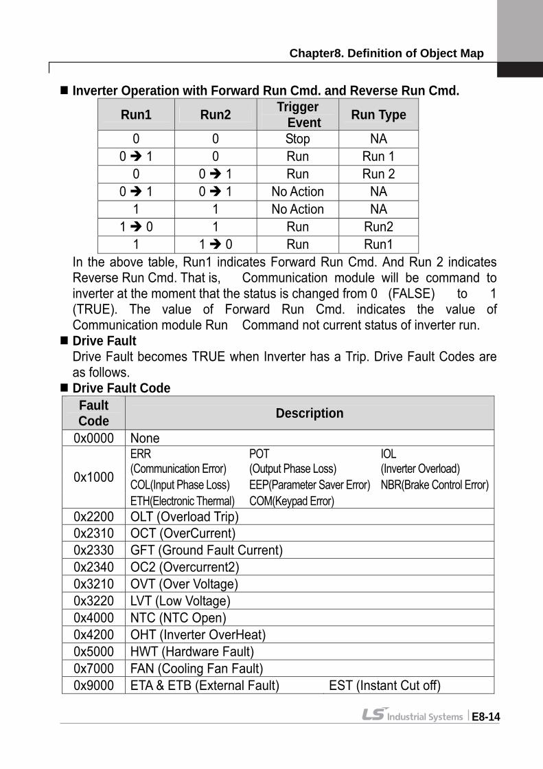
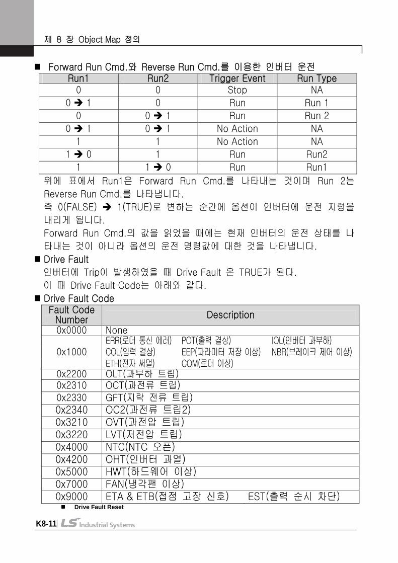
Inverter Operation with Forward Run Cmd. and Reverse Run Cmd.
Run1 Run2 Trigger Event Run Type
0 0 Stop NA 0 1 0 Run Run 1
0 0 1 Run Run 2 0 1 0 1 No Action NA
1 1 No Action NA 1 0 1 Run Run2
1 1 0 Run Run1 In the above table, Run1 indicates Forward Run Cmd. And Run 2 indicates
Reverse Run Cmd. That is, Communication module will be command to inverter at the moment that the status is changed from 0 (FALSE) to 1 (TRUE). The value of Forward Run Cmd. indicates the value of Communication module Run Command not current status of inverter run.
Drive Fault Drive Fault becomes TRUE when Inverter has a Trip. Drive Fault Codes are
as follows. Drive Fault Code
Fault Code Description
0x0000 None ERR (Communication Error)
POT (Output Phase Loss)
IOL (Inverter Overload)
COL(Input Phase Loss) EEP(Parameter Saver Error) NBR(Brake Control Error)0x1000
ETH(Electronic Thermal) COM(Keypad Error) 0x2200 OLT (Overload Trip) 0x2310 OCT (OverCurrent) 0x2330 GFT (Ground Fault Current) 0x2340 OC2 (Overcurrent2) 0x3210 OVT (Over Voltage) 0x3220 LVT (Low Voltage) 0x4000 NTC (NTC Open) 0x4200 OHT (Inverter OverHeat) 0x5000 HWT (Hardware Fault) 0x7000 FAN (Cooling Fan Fault) 0x9000 ETA & ETB (External Fault) EST (Instant Cut off)
Chapter8. Definition of Object Map
E8-15
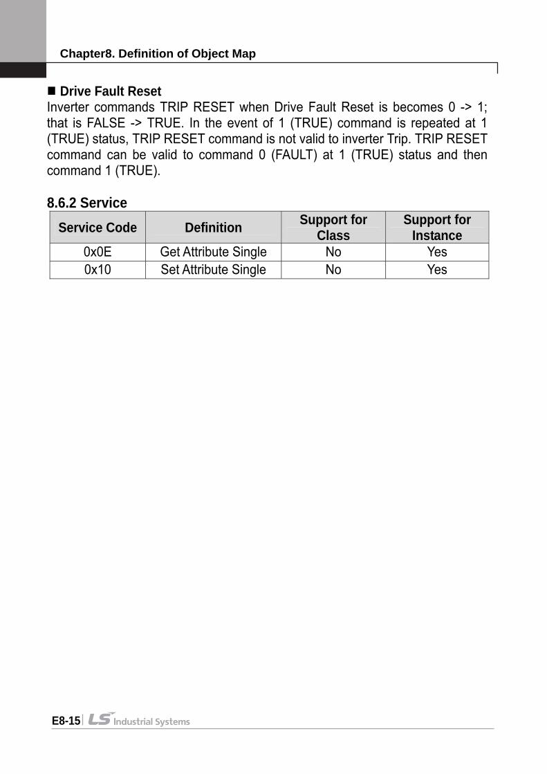
Drive Fault Reset Inverter commands TRIP RESET when Drive Fault Reset is becomes 0 -> 1; that is FALSE -> TRUE. In the event of 1 (TRUE) command is repeated at 1 (TRUE) status, TRIP RESET command is not valid to inverter Trip. TRIP RESET command can be valid to command 0 (FAULT) at 1 (TRUE) status and then command 1 (TRUE). 8.6.2 Service
Service Code Definition Support for Class
Support for Instance
0x0E Get Attribute Single No Yes 0x10 Set Attribute Single No Yes
Chapter8. Definition of Object Map
E8-16
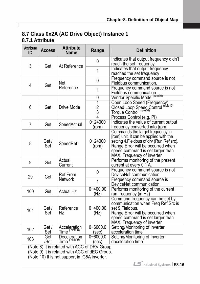
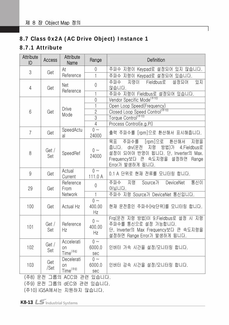
8.7 Class 0x2A (AC Drive Object) Instance 1 8.7.1 Attribute
(Note 8) It is related with ACC of DRV Group. (Note 9) It is related with ACC of dEC Group. (Note 10) It is not support in iG5A inverter.
Attribute ID Access Attribute
Name Range Definition
0 Indicates that output frequency didn’t reach the set frequency. 3 Get At Reference
1 Indicates that output frequency reached the set frequency
0 Frequency command source is not Fieldbus communication. 4 Get Net
Reference 1 Frequency command source is not Fieldbus communication.
0 Vendor Specific Mode (note10) 1 Open Loop Speed (Frequency) 2 Closed Loop Speed Control (note10) 3 Torque Control (note10)
6 Get Drive Mode
4 Process Control (e.g. PI) 7 Get SpeedActual 0~24000
(rpm) Indicates the value of current output frequency converted into [rpm].
8 Get / Set SpeedRef 0~24000
(rpm)
Commands the target frequency in [rpm] unit. It can be applied with the setting 4.Fieldbus of drv (Run Ref src). Range Error will be occurred when speed command is set larger than MAX. Frequency of inverter.
9 Get Actual Current - Performs monitoring of the present
current at every 0.1 A. 0 Frequency command source is not
DeviceNet communication 29 Get Ref.From Network 1 Frequency command source is
DeviceNet communication. 100 Get Actual Hz 0~400.00
(Hz) Performs monitoring of the current run frequency (in Hz)
101 Get / Set
Reference Hz
0~400.00 (Hz)
Command frequency can be set by communication when Freq Ref Src is set 9.Fieldbus. Range Error will be occurred when speed command is set larger than MAX. Frequency of inverter.
102 Get / Set
Acceleration Time ( Note 8)
0~6000.0 (sec)
Setting/Monitoring of Inverter acceleration time
103 Get /Set
Deceleration Time ( Note 9)
0~6000.0 (sec)
Setting/Monitoring of Inverter deceleration time
Chapter8. Definition of Object Map
E8-17
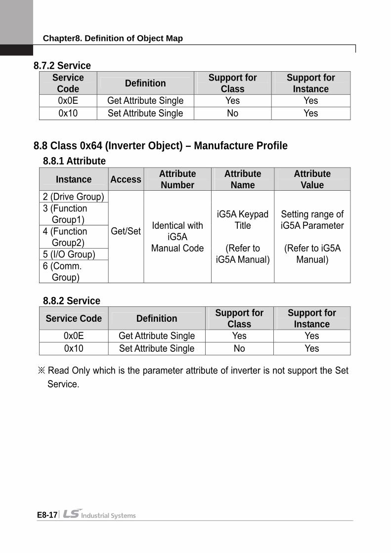
8.7.2 Service Service Code Definition Support for
Class Support for
Instance 0x0E Get Attribute Single Yes Yes 0x10 Set Attribute Single No Yes
8.8 Class 0x64 (Inverter Object) – Manufacture Profile 8.8.1 Attribute
Instance Access Attribute Number
Attribute Name
Attribute Value
2 (Drive Group) 3 (Function Group1) 4 (Function Group2) 5 (I/O Group) 6 (Comm. Group)
Get/Set
Identical with iG5A
Manual Code
iG5A Keypad Title
(Refer to
iG5A Manual)
Setting range of iG5A Parameter
(Refer to iG5A
Manual)
8.8.2 Service
Service Code Definition Support for Class
Support for Instance
0x0E Get Attribute Single Yes Yes 0x10 Set Attribute Single No Yes
※ Read Only which is the parameter attribute of inverter is not support the Set
Service.
Warranty
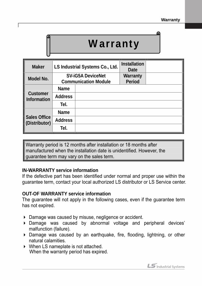
Maker LS Industrial Systems Co., Ltd. Installation Date
Model No. SV-iG5A DeviceNet Communication Module
Warranty Period
Name Address Customer
Information Tel.
Name Address Sales Office
(Distributor) Tel.
Warranty period is 12 months after installation or 18 months after manufactured when the installation date is unidentified. However, the guarantee term may vary on the sales term.
IN-WARRANTY service information If the defective part has been identified under normal and proper use within the guarantee term, contact your local authorized LS distributor or LS Service center. OUT-OF WARRANTY service information The guarantee will not apply in the following cases, even if the guarantee term has not expired.
Damage was caused by misuse, negligence or accident. Damage was caused by abnormal voltage and peripheral devices’ malfunction (failure).
Damage was caused by an earthquake, fire, flooding, lightning, or other natural calamities.
When LS nameplate is not attached. When the warranty period has expired.
Warranty
안전상의 주의사항
i
제품을 사용하기 전에
먼저 LS산전 iG5A 시리즈 DeviceNet 통신 모듈을 사용하여 주셔서 감사합니다.
안전상의 주의사항
안전상의 주의사항은 사고나 위험을 사전에 예방하여 제품을 안전하고 올
바르게 사용하기 위한 것이므로 반드시 지켜주십시오.
주의사항은 ‘경고’와 ‘주의’의 두 가지로 구분되어 있으며 ‘경고’와 ‘주의’
의 의미는 다음과 같습니다.
경 고 지시사항을 위반할 때 심각한 상해나 사망이 발생할 가능성이
있는 경우 주 의 지시사항을 위반할 때 경미한 상해나 제품손상이 발생할 가능성
이 있는 경우
제품과 사용설명서에 표시된 그림기호의 의미는 다음과 같습니다. 는 위험이 발생할 우려가 있으므로 주의하라는 기호입니다.
는 감전의 가능성이 있으므로 주의하라는 기호입니다.
사용설명서를 읽고 난 후 사용하는 사람이 언제라도 볼 수 있는 장소에
보관 하십시오.
SV-iG5A 시리즈 인버터의 기능을 충분하고 안전하게 사용하기 위하여 이
사용 설명서를 잘 읽어 보십시오.
주 의 옵션보드의 CMOS 소자들의 취급에 주의하십시오.
정전기에 의한 고장의 원인이 됩니다.
통신 신호선 등의 변경 접속은 인버터 전원을 내린 상태에서 하십시오.
통신불량 및 고장의 원인이 됩니다.
인버터 본체와 옵션보드 커넥터가 정확히 일치하게 접속되도록 하십시오.
통신불량 및 고장의 원인이 됩니다.
파라미터를 설정할 때는 파라미터 Unit 을 확인하시기 바랍니다.
통신불량의 원인이 됩니다.
목차
ii
목 차
제1장 소 개 - - - - - K1 – 1
제2장 DeviceNet 통신 모듈 규격 - - - - - K2 – 1
제3장 DeviceNet 통신 Cable 규격 - - - - - K3 – 1
제4장 설 치 - - - - - K4 – 1
4.1 구성품 - - - - - K4 – 1
4.2 DeviceNet 통신 모듈 내부 구성 - - - - - K4 – 1
4.3 DeviceNet 통신 단자대 규격 - - - - - K4 – 1
4.4 제어 단자대 규격(Control I/O) - - - - - K4 – 2
4.5 DeviceNet 통신 모듈 장착 방법 및 순서 - - - - - K4 – 3
4.6 설치 시 주의 사항 - - - - - K4 – 4
제5장 DeviceNet 통신 모듈 LED Display - - - - - K5 – 1
5.1 NS LED 상태 - - - - - K5 – 1
5.2 MS LED 상태 - - - - - K5 – 2
5.3 LED Tip - - - - - K5 – 3
5.3.1 Reset이 발생했을 경우 - - - - - K5 – 3 5.3.2 Scanner(Master)에 의해서 EMC가 연결된 경우 - - - - - K5 – 3
제6장 EDS(Electronic Data Sheets) File - - - - - K6 – 1
제7장 DeviceNet 통신 관련 파라미터 리스트 - - - - - K7 – 1
7.1 Fieldbus ID (C3) - - - - - K7 – 3 7.2 Fieldbus Baudrate (C4) - - - - - K7 – 3 7.3 Fieldbus LED (C5) - - - - - K7 – 4 7.4 In Instance, Out Instance (C29, C49) - - - - - K7 – 4
제8장 Object Map 정의 - - - - - K8 – 1
8.1 Class 0x01 (Identity Object) Instance 1 - - - - - K8 – 1 8.1.1 Attribute - - - - - K8 – 1 8.1.2 Service - - - - - K8 – 2 8.2 Class 0x03 (DeviceNet Object) Instance 1 - - - - - K8 – 2 8.2.1 Attribute - - - - - K8 – 2 8.2.2 Service - - - - - K8 – 3 8.3 Class 0x04 (Assembly Object) - - - - - K8 – 3 8.3.1 In Instance 70/110 - - - - - K8 – 3 8.3.2 In Instance 71/111 - - - - - K8 – 4 8.3.3 In Instance 141/142/143/144 - - - - - K8 – 5
목차
iii
8.3.4 Out Instance 20/100 - - - - - K8 – 6 8.3.5 Out Instance 21/101 - - - - - K8 – 6 8.3.6 Out Instance 121/122/123/124 - - - - - K8 – 7 8.4 Class 0x05 (DeviceNet Connection Object) - - - - - K8 – 8 8.4.1 Instance - - - - - K8 – 8 8.4.2 Attribute - - - - - K8 – 8 8.4.3 Service - - - - - K8 – 8 8.5 Class 0x28 (Motor Data Object) Instance 1 - - - - - K8 – 9 8.5.1 Attribute - - - - - K8 – 9 8.5.2 Service - - - - - K8 – 9 8.6 Class 0x29 (Control Supervisor Object) Instance 1 - - - - - K8 – 10 8.6.1 Attribute - - - - - K8 – 10 8.6.2 Service - - - - - K8 – 12 8.7 Class 0x2A (AC Drive Object) Instance 1 - - - - - K8 – 13 8.7.1 Attribute - - - - - K8 – 13 8.7.2 Service - - - - - K8 – 14 8.8 Class 0x64 (Inverter Object) – Manufacture Profile - - - - - K8 – 14 8.8.1 Attribute - - - - - K8 – 14 8.8.2 Service - - - - - K8 – 14
제 1 장 소개
K1-1
제 1 장 소 개
iG5A DeviceNet 통신 모듈은 SV-iG5A 인버터를 DeviceNet 네트워크에 연
결되도록 합니다.
DeviceNet 통신 모듈을 사용하면 인버터의 제어 및 모니터링이 PLC의 시
퀀스 프로그램 또는 임의의 Master Module에 의해 제어가 가능해 집니다.
하나의 통신 선으로 다수의 인버터가 접속 동작하므로 통신을 사용하지 않
을 경우보다 설치 비용을 줄일 수 있습니다.
또한 배선이 간단하므로 설치 시간을 절감할 수 있고 유지 보수가 쉬워 집
니다.
인버터의 제어를 위해서 PLC등의 각종 주변장치를 이용할 수 있고 PC등
각종 시스템과 연계 동작이 가능하여 공장 자동화가 용이합니다.
제 2 장 DeviceNet 통신 모듈 규격
K2-1
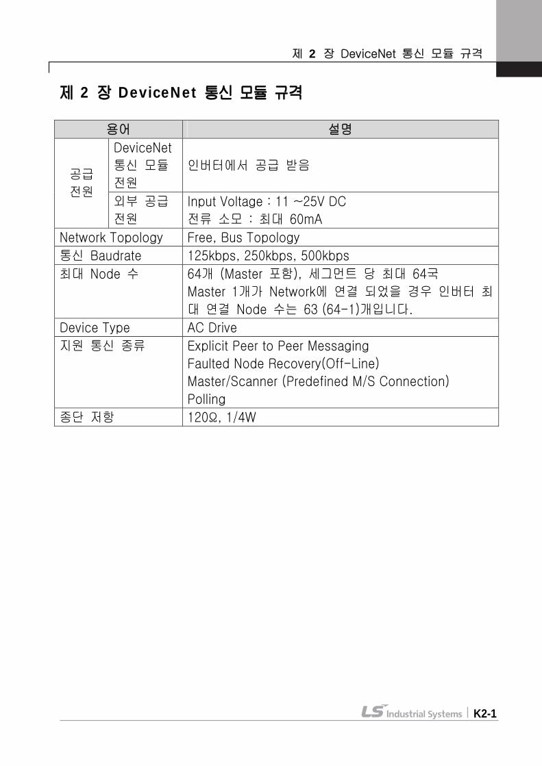
제 2 장 DeviceNet 통신 모듈 규격
용어 설명
DeviceNet
통신 모듈
전원
인버터에서 공급 받음 공급
전원 외부 공급
전원
Input Voltage : 11 ~25V DC
전류 소모 : 최대 60mA
Network Topology Free, Bus Topology
통신 Baudrate 125kbps, 250kbps, 500kbps
최대 Node 수 64개 (Master 포함), 세그먼트 당 최대 64국
Master 1개가 Network에 연결 되었을 경우 인버터 최
대 연결 Node 수는 63 (64-1)개입니다.
Device Type AC Drive
지원 통신 종류 Explicit Peer to Peer Messaging
Faulted Node Recovery(Off-Line)
Master/Scanner (Predefined M/S Connection)
Polling
종단 저항 120Ω, 1/4W
제 3 장 DeviceNet 통신 Cable 규격
K3-1
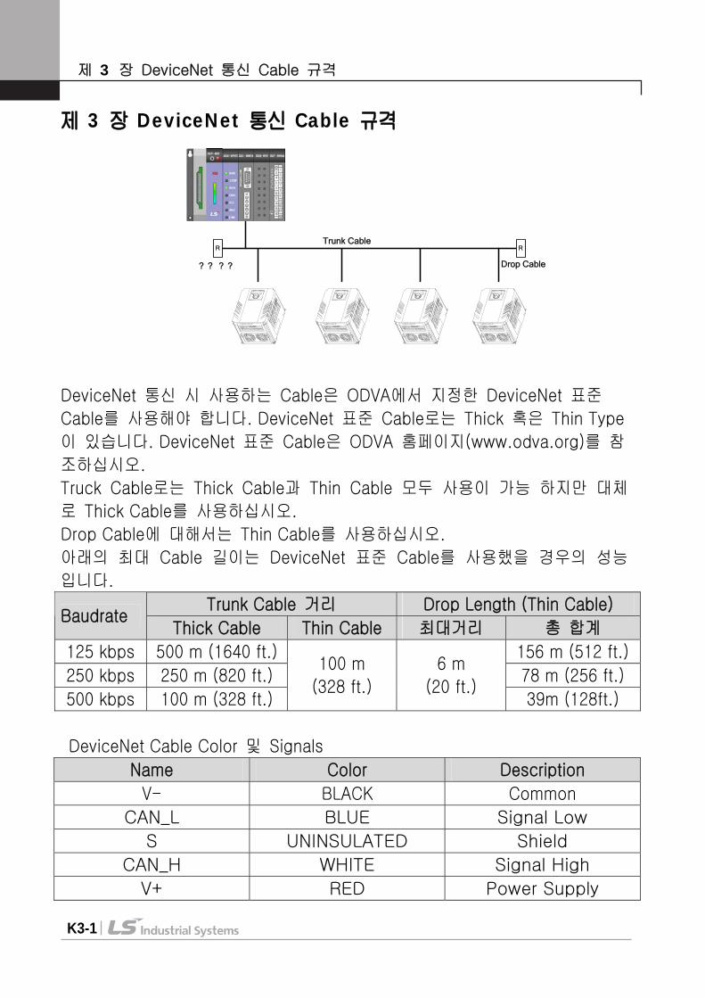
제 3 장 DeviceNet 통신 Cable 규격
DeviceNet 통신 시 사용하는 Cable은 ODVA에서 지정한 DeviceNet 표준
Cable를 사용해야 합니다. DeviceNet 표준 Cable로는 Thick 혹은 Thin Type
이 있습니다. DeviceNet 표준 Cable은 ODVA 홈페이지(www.odva.org)를 참
조하십시오.
Truck Cable로는 Thick Cable과 Thin Cable 모두 사용이 가능 하지만 대체
로 Thick Cable를 사용하십시오.
Drop Cable에 대해서는 Thin Cable를 사용하십시오.
아래의 최대 Cable 길이는 DeviceNet 표준 Cable를 사용했을 경우의 성능
입니다.
Trunk Cable 거리 Drop Length (Thin Cable) Baudrate
Thick Cable Thin Cable 최대거리 총 합계
125 kbps 500 m (1640 ft.) 156 m (512 ft.)
250 kbps 250 m (820 ft.) 78 m (256 ft.)
500 kbps 100 m (328 ft.)
100 m
(328 ft.)
6 m
(20 ft.) 39m (128ft.)
DeviceNet Cable Color 및 Signals
Name Color Description
V- BLACK Common
CAN_L BLUE Signal Low
S UNINSULATED Shield
CAN_H WHITE Signal High
V+ RED Power Supply
Trunk Cable
Drop Cable
R R
? ? ? ?
제 4 장 설치
K4-1
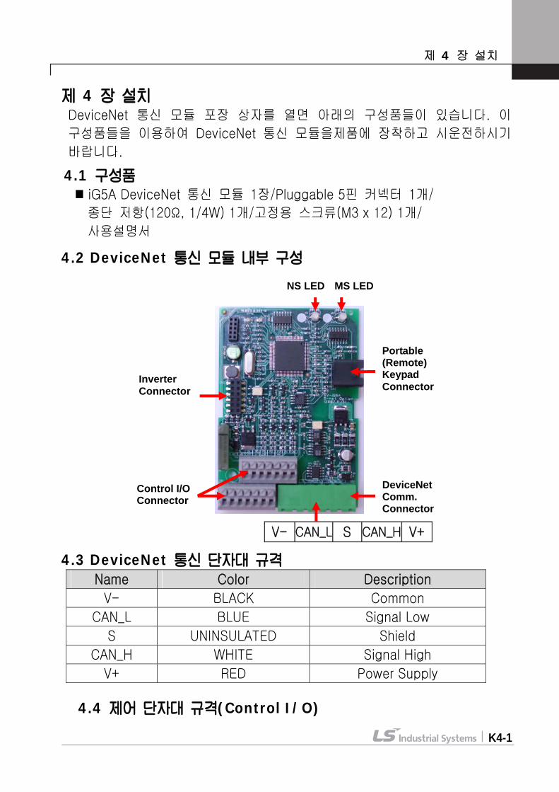
제 4 장 설치 DeviceNet 통신 모듈 포장 상자를 열면 아래의 구성품들이 있습니다. 이
구성품들을 이용하여 DeviceNet 통신 모듈을제품에 장착하고 시운전하시기
바랍니다. 4.1 구성품
iG5A DeviceNet 통신 모듈 1장/Pluggable 5핀 커넥터 1개/
종단 저항(120Ω, 1/4W) 1개/고정용 스크류(M3 x 12) 1개/
사용설명서
4.2 DeviceNet 통신 모듈 내부 구성
V- CAN_L S CAN_H V+
4.3 DeviceNet 통신 단자대 규격
4.4 제어 단자대 규격(Control I/O)
Name Color Description
V- BLACK Common
CAN_L BLUE Signal Low
S UNINSULATED Shield
CAN_H WHITE Signal High
V+ RED Power Supply
NS LED MS LED
Inverter Connector
DeviceNet Comm. Connector
Control I/O Connector
Portable (Remote) Keypad Connector
제 4 장 설치
K4-2
단자 종류 단자 명칭 전기적 규격
P1 ~ P4 다기능 입력 단자 1-4
CM 접점 공통 단자
VR
외부 볼륨 저항용 전원단자 출력전압 : 12V
최대출력전류: 100mA
볼륨저항 : 1 ~ 5kΩ
V1 전압 운전용 입력 단자 최대입력전압:
-10V ~ +10V 입력
I 전류 운전용 입력 단자 0 ~ 20mA 입력
(내부저항 : 250Ω)
AM 다기능 아날로그 출력 단자 최대출력전압 : 11[V]
최대출력전류 : 10mA
MO 다기능 단자(오픈 컬렉터) DC 26V, 100mA 이하
MG 외부 전원용 접지 단자
3A 다기능 릴레이 출력 A접점 AC 250V, 1A 이하
3C 다기능 릴레이 접점 공통 단자
주1) 제어 배선을 케이블 타이등을 이용하여 정리할 경우 제어 단자대에
서 15cm 이상 떨어진 곳에 작업하십시오. 그렇지 않을 경우 전면
덮개가 조립되지 않을 수 있습니다.
주2) 전선은 600V, 75 이상의 동전선을 사용하여 주십시오.
MO MG VR V1 I AM
3A 3C P1 P2 P3 P4 CM
I

제 4 장 설치
K4-3
4.5 DeviceNet 통신 모듈 장착 방법 및 순서
iG5A 통신용 제품(①)에서 상부 커버(②,③)을 벗겨내고 통신 모듈(④)를 제품 하부 커버(⑤)에 장착합니다.
통신 모듈(④) 장착 후 먼저 상부 커버(②)를 장착하시기 바랍니다. 제어에 필요한 통신 및 I/O 신호선들을 연결해 주시기 바랍니다. 기본 연결이 완료되면 상부 커버(③)을 장착하시기 바랍니다. 본 통신 모듈은 Non Loader 타입이기 때문에 파라미터 설정 혹은 판넬 취부가 필요한 경우에는 아래 그림에 있는 Portable Keypad(⑥)나 판넬 취부형 Remote Keypad를 사용하시기 바랍니다.
Step 4
Step 5
⑥
Step 1 Step 2 Step 3
②
③ ④
⑤
①
제 4 장 설치
K4-4
4.6 설치 시 주의 사항
전원이 켜진 상태에서 DeviceNet 통신 모듈을 장착 혹은 제거 하지 마
십시오. DeviceNet 통신 모듈과 인버터 본체 모두가 파손될 수 있습니다.
인버터 내부의 커패시터 전압이 완전히 방전된 후 DeviceNet 통신 모듈
을 장착 혹은 제거 하십시오.
인버터 전원이 켜진 상태에서 통신 신호선 등의 변경 접속을 하지 마십
시오.
인버터 본체와 옵션보드 커넥터가 정확히 일치하여 접속되도록 주의 하
십시오.
통신 전원(24P, 24G)을 연결 시 DeviceNet 통신 모듈의 V-(24G),
V+(24P) Silk를 확인 하고 바르게 연결 하십시오. 오 배선 시에는 통신
이 정상적으로 이루어지지 못하므로 주의 바랍니다.
Network 구성 시 맨 끝에 연결된 Device에 반드시 종단 저항을 연결 하
십시오. 종단 저항은 CAN_L과 CAN_H 사이에 연결하면 되고 종단 저항
값은 120Ω, 1/4W입니다.
iG5A DeviceNet 통신 옵션 모듈을 사용하기 위해서는 반드시 iG5A 통
신형 본체를 사용하여야 합니다.
Software는 Version 2.3부터 지원 됩니다. (Software Version은 기능그룹
2의 H79번에서 확인 가능합니다.)
제 5 장 DeviceNet 통신 모듈 LED Display
K5-1
제 5 장 DeviceNet 통신 모듈 LED Display DeviceNet 통신 모듈에는 현재의 통신 상태를 알려주는 2개의 LED가 장착 되어 있습니다. MS(Module Status) LED와 NS(Network Status)LED 가 있으며, 이 두 LED의 기본 기능은 아래와 같습니다.
MS LED (Module Status)
DeviceNet 통신 모듈의 전원상태가 안정되고 DeviceNet 통신 모듈의 CPU가 정상동작을 하는지 그리고 DeviceNet 통신모듈과 인버터 본체간의 Interface 통신이 바르게 이루어지는지 확인 하는 데 사용됩니다. 위에서 설명한 모든 동작이 정상적일 경우 MS LED는 녹색입니다. (Solid Green)
NS LED (Network Status)
Network상에서 DeviceNet 통신 모듈의 통신 연결상태나Network 전원의 상태들을 나타내는데 사용됩니다.
5.1 NS LED 상태 LED 상 태 원 인 도 움
DeviceNet 통신 모듈에 5V 전원이 확립되지 않았습니다.
인버터 전원이 인가되었는지 확인하시기 바랍니다.
꺼짐 Off-Line (No Power)
MAC ID 중복 체크 중 입니다.
전원이 들어 갔을 때 옵션 초기화 이후에 MAC ID 중복 체크를 하는 동안에 꺼져 있으므로 5초 정도 기다리면 됩니다.
녹색 점멸
On-Line Not Connected
중복 노드의 확인이 끝나고 통신환경이 갖추어졌지만 아직 어느 노드하고도 연결이 되어 있지 않은 상태입니다.
사용자가 연결을 시도하기 전의 정상적인 동작입니다.
녹색 고정
On-Line, Connected (Link OK)
하나 이상의 EMC(Explicit Message Connection) 연결이 확립되어 있습니다.
I/O 통신(Poll) 연결이 가능한 상태입니다.
적색 점멸
Connection Time-Out Critical Link Failure.
Poll I/O 통신 중에 timed out 이 발생했습니다.
[Slave] Inverter Comm. Update(C99)를 합니다. [Master] PLC 인버터 Reset Identity Object에 Reset 하고 I/O
제 5 장 DeviceNet 통신 모듈 LED Display
K5-2
LED 상 태 원 인 도 움
연결을 다시 합니다.
Network에 중복된 MAC ID가 존재합니다.
MAC ID 설정을 확인 바랍니다.
Network 구성으로부터 Bus Off가 된 상태입니다.
신호선의 연결이 잘 되어 있는지의 여부를 점검 하고 Comm. Update를 합니다.
적색 고정 이상 발생
DeviceNet 커넥터를 통해 들어오는 Network 전원이 공급되지 않았습니다.
Network 연결이 잘 연결되었는지 확인하고, Network 전원 공급장치를 확인합니다.
녹색
적색
점멸
자체 진단 자체 진단 중 입니다. 잠시만 기다리십
시오.
적색
녹색
점멸
Communi-
cation
Fault
Network Access 통과 실패로
Communication Fault 상태에
들어와 있고 이 때 Identity
Communication Faulted
Request Message를 받아들였
을 경우 발생합니다.
정상적인 반응입
니다.
5.2 MS LED 상태 LED 상 태 원 인 도 움
꺼짐 No Power DeviceNet 통신 모듈에5V 전원이 확립되지 않았습니다.
인버터 전원이 인가되었는지 확인하시기바랍니다.
녹색 고정
Operational 정상 동작입니다.
적색 고정
Unrecoverable Fault
DeviceNet 통신 모듈과인버터간의 Interface 통신이 제대로 이루어지지못하고 있는 상황입니다.
DeviceNet 통신 모듈과 인버터간의 연결상태를 점검하시기바랍니다.
녹색적색 점멸
Self Test DeviceNet 통신 모듈은현재 자체진단 중입니다.

제 5 장 DeviceNet 통신 모듈 LED Display
K5-3
5.3 LED Tip 5.3.1 Reset이 발생했을 경우
우선 MS(Module Status) LED를 0.5초 간격으로 녹색 – 빨간색으로 점멸하고 DeviceNet 통신 모듈과 인버터간의 Interface 통신이 정상 동작 시 녹색으로 고정됩니다.
뒤이어 NS(Network Status) LED를 0.5초 간격으로 녹색 – 빨간색으로 점멸합니다.
중복 MAC ID를 점검한 후 이상이 없으면 Network Status LED를 녹색으로 점멸합니다. 이는 본 Device 통신 모듈이 정상적으로 네트워크에 연결 되었음을 의미합니다. 하지만 아직 다른 어느 Device와 통신은 하고 있지 않습니다.
위와 같이 동작하지 않는 경우에는 다음의 세 가지 상황을 살펴보시기 바랍니다. 정상적으로 동작 시에는 아래의 경우는 무시하셔도 됩니다.
만일 DeviceNet 통신 모듈과 인버터간의 Interface통신이 정상적으로 동작하지 못할 경우에는 MS(Module Status) LED는 빨간색으로 고정됩니다. 이때는 인버터와 DeviceNet 통신 모듈과의 연결을 우선 점검하고 인버터 전원을 올리십시오.
만일 중복 MAC ID점검에서 이상이 생기면 Network Status LED는 빨간색으로 고정됩니다. 이 경우에는 Keypad를 사용하여 MAC ID를 다른 값으로 설정 하십시오. 옵션보드가 다른 Device와 통신을 하고 있는 경우에는 NS(Network Status) LED는 녹색으로 고정됩니다.
5.3.2 Scanner(Master)에 의해서 EMC(Explicit Message
Connection)가 연결된 경우 Network Status LED가 녹색 고정상태로 됩니다. 이 상태에서 만일 EMC설정이 해제가 되면 약 10초 경과 후 다시 초록색으로 점멸합니다. 일단 EMC가 연결되면 I/O Connection을 만들 수 있습니다. 이때의 Network Status LED의 상태는 변함 없습니다.
만일 I/O Connection 설정 시간 내에 통신이 이루어지지 않으면 Time Out이 발생하고 Network Status LED는 빨간색으로 점멸합니다. (EMC의 시간설정에 따라 이 Status는 다시 초록색 점멸로 될 수도 있습니다)
EMC만 연결되고 I/O Connection을 하지 않았을 경우 선이 빠져도 Green LED가 계속 ON되어 있습니다.
제 6 장 EDS File
K6-1
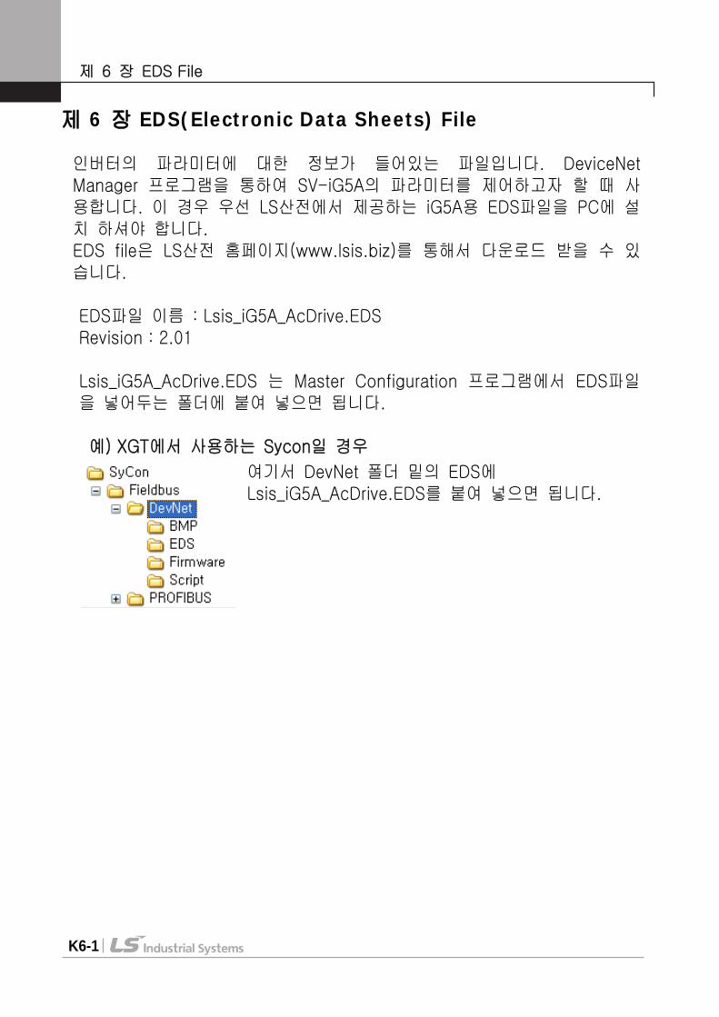
제 6 장 EDS(Electronic Data Sheets) File
인버터의 파라미터에 대한 정보가 들어있는 파일입니다. DeviceNet Manager 프로그램을 통하여 SV-iG5A의 파라미터를 제어하고자 할 때 사용합니다. 이 경우 우선 LS산전에서 제공하는 iG5A용 EDS파일을 PC에 설치 하셔야 합니다. EDS file은 LS산전 홈페이지(www.lsis.biz)를 통해서 다운로드 받을 수 있습니다.
EDS파일 이름 : Lsis_iG5A_AcDrive.EDS Revision : 2.01 Lsis_iG5A_AcDrive.EDS 는 Master Configuration 프로그램에서 EDS파일을 넣어두는 폴더에 붙여 넣으면 됩니다. 예) XGT에서 사용하는 Sycon일 경우
여기서 DevNet 폴더 밑의 EDS에 Lsis_iG5A_AcDrive.EDS를 붙여 넣으면 됩니다.
제 7 장 DeviceNet 통신 관련 파라미터 리스트
K7-1
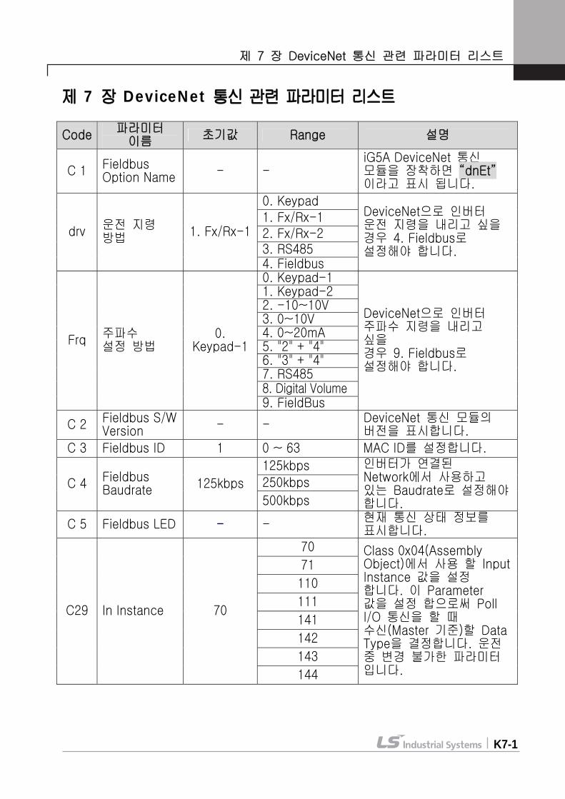
제 7 장 DeviceNet 통신 관련 파라미터 리스트
Code 파라미터 이름 초기값 Range 설명
C 1 Fieldbus Option Name - -
iG5A DeviceNet 통신 모듈을 장착하면 “dnEt” 이라고 표시 됩니다.
0. Keypad 1. Fx/Rx-1 2. Fx/Rx-2 3. RS485
drv 운전 지령 방법 1. Fx/Rx-1
4. Fieldbus
DeviceNet으로 인버터 운전 지령을 내리고 싶을 경우 4. Fieldbus로 설정해야 합니다.
0. Keypad-1 1. Keypad-2 2. -10~10V 3. 0~10V 4. 0~20mA 5. "2" + "4" 6. "3" + "4" 7. RS485 8. Digital Volume
Frq 주파수 설정 방법
0. Keypad-1
9. FieldBus
DeviceNet으로 인버터 주파수 지령을 내리고 싶을 경우 9. Fieldbus로 설정해야 합니다.
C 2 Fieldbus S/W Version - - DeviceNet 통신 모듈의
버전을 표시합니다.
C 3 Fieldbus ID 1 0 ~ 63 MAC ID를 설정합니다.
125kbps
250kbps C 4 Fieldbus Baudrate 125kbps
500kbps
인버터가 연결된 Network에서 사용하고 있는 Baudrate로 설정해야 합니다.
C 5 Fieldbus LED - - 현재 통신 상태 정보를 표시합니다.
70
71
110
111
141
142
143
C29 In Instance 70
144
Class 0x04(Assembly Object)에서 사용 할 Input Instance 값을 설정 합니다. 이 Parameter 값을 설정 합으로써 Poll I/O 통신을 할 때 수신(Master 기준)할 Data Type을 결정합니다. 운전 중 변경 불가한 파라미터 입니다.
제 7 장 DeviceNet 통신 관련 파라미터 리스트
K7-2
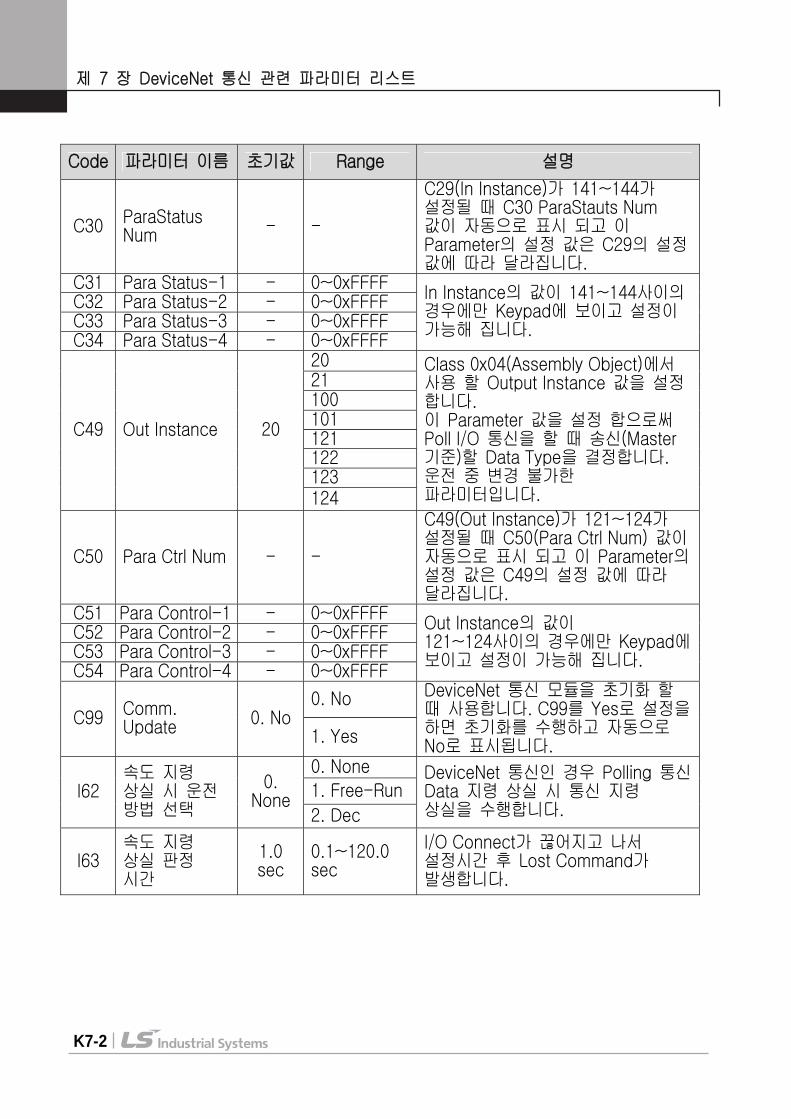
Code 파라미터 이름 초기값 Range 설명
C30 ParaStatus Num - -
C29(In Instance)가 141~144가 설정될 때 C30 ParaStauts Num 값이 자동으로 표시 되고 이 Parameter의 설정 값은 C29의 설정 값에 따라 달라집니다.
C31 Para Status-1 - 0~0xFFFF C32 Para Status-2 - 0~0xFFFF C33 Para Status-3 - 0~0xFFFF C34 Para Status-4 - 0~0xFFFF
In Instance의 값이 141~144사이의 경우에만 Keypad에 보이고 설정이 가능해 집니다.
20 21 100 101 121 122 123
C49 Out Instance 20
124
Class 0x04(Assembly Object)에서 사용 할 Output Instance 값을 설정 합니다. 이 Parameter 값을 설정 합으로써 Poll I/O 통신을 할 때 송신(Master 기준)할 Data Type을 결정합니다. 운전 중 변경 불가한 파라미터입니다.
C50 Para Ctrl Num - -
C49(Out Instance)가 121~124가 설정될 때 C50(Para Ctrl Num) 값이 자동으로 표시 되고 이 Parameter의 설정 값은 C49의 설정 값에 따라 달라집니다.
C51 Para Control-1 - 0~0xFFFF C52 Para Control-2 - 0~0xFFFF C53 Para Control-3 - 0~0xFFFF C54 Para Control-4 - 0~0xFFFF
Out Instance의 값이 121~124사이의 경우에만 Keypad에 보이고 설정이 가능해 집니다.
0. No C99 Comm.
Update 0. No 1. Yes
DeviceNet 통신 모듈을 초기화 할 때 사용합니다. C99를 Yes로 설정을 하면 초기화를 수행하고 자동으로 No로 표시됩니다.
0. None
1. Free-Run I62 속도 지령 상실 시 운전 방법 선택
0. None
2. Dec
DeviceNet 통신인 경우 Polling 통신 Data 지령 상실 시 통신 지령 상실을 수행합니다.
I63 속도 지령 상실 판정 시간
1.0 sec
0.1~120.0 sec
I/O Connect가 끊어지고 나서 설정시간 후 Lost Command가 발생합니다.
제 7 장 DeviceNet 통신 관련 파라미터 리스트
K7-3
7.1 Fieldbus ID (C3) Fieldbus ID는 DeviceNet에서 이야기하는 MAC ID(Media Access
Control Identifier)에 해당합니다. 이 값은 DeviceNet Network에서 각 Device를 구별하는 고유의 값이므
로 서로 다른 Device가 같은 값을 공유할 수 없습니다. 출하 시 이 값은 1로 되어 있으며 만일 DeviceNet 통신 모듈과 인버터
간 Interface 통신에 문제가 발생하게 되면 MAC ID를 변경해 보십시오. 운전 도중에 MAC ID를 변경하면 DeviceNet 통신 모듈은 자동으로
Reset됩니다. 이는 새로 설정된 MAC ID값을 사용하는 Device가 Network상에 있는지의 여부를 확인하는 작업을 반드시 하여야 하기 때문입니다.
만일 설정한 MAC ID값이 이미 다른 Device에서 사용하고 있는 값일 경우 NS(Network Status) LED가 빨간색 고정으로 변합니다. 이때에는 다시 Keypad를 이용하여 MAC ID를 다른 값으로 변경합니다. 이 후 NS가 초록색 점멸이면 정상적으로 동작하는 것입니다.
7.2 Fieldbus Baudrate (C4)
Network에서 사용하고 있는 통신 속도로 설정하지 않은 경우 NS LED는 Off상태를 유지합니다.
Keypad를 이용해서 Baudrate를 변경하면 변경된 Baudrate 값이 실제 통신 속도에 영향을 미치기 위해서는 통신을 통해 인버터의 Identity Object에 Reset Service를 보내거나 인버터를 Reset시켜야 합니다.
C99(Comm. Update)를 이용해서 인버터를 Reset 시켜도 됩니다. ※ Network Baudrate와 통신 모듈의 Baudrate가 일치하고 MAC ID가 유
일하면 NS LED가 녹색 점멸 상태가 됩니다.

제 7 장 DeviceNet 통신 관련 파라미터 리스트
K7-4
7.3 Fieldbus LED (C5) DeviceNet 통신 모듈에는 2개의 MS LED, NS LED만 있지만 Keypad로 C5(Fieldbus LED Status)를 보면 4개의 LED가 보입니다. C5의 LED 순서에 따라 (왼쪽 오른쪽) NS LED Red, NS LED Green, MS LED Red, MS LED Green 정보를 표시 해 줍니다.
만약 C5가 아래와 같이 표시 되어 있다면 현재 NS LED가 Green이고 MS LED가 Green임을 나타납니다.
Fieldbus LED(C5) 상태 예
7.4 In Instance, Out Instance (C29, C49)
In Instance, Out Instance는 Poll I/O 데이터 통신을 하는데 사용됩니다. Poll I/O Connection은 Scanner(Master)와 인버터 사이에 특정 데이터를 통신하는 Connection입니다. Poll I/O를 통해서 전달되는 data의 Type은 Assembly Instance (C29, C49)에 의해서 정해집니다. Instance 20, 21, 100, 101, 70, 71, 110, 111인 경우 Poll I/O 통신에 의해서 전달 되는 데이터는 양 방향 모두 4Bytes 이고, 통신 주기 default값은 0(zero)입니다. Assembly Instance는 크게 Output 그리고 Input으로 나눌 수 있습니다. 여기서 Input, Out은 Scanner를 기준입니다. 즉 Input Data는 Scanner로 들어가는 data를 나타냅니다. 따라서 인버터 입장에서는 인버터가 Scanner에게 Feedback 해 주는 값이 됩니다. Output Data는 이와 반대로 Scanner에서 나오는 Data로 인버터의 입장에서는 새로운 지령 값이 됩니다. In Instance 혹은 Out Instance 값 변경 시 DeviceNet 통신 모듈은 자동으로 Reset 합니다.
NS LED Red NS LED Green MS LED Red MS LED GreenOFF ON OFF ON
Scanner (Master)
iG5A Inverter
Output Assembly
Input Assembly
NS LED MS LED
Red Green Red Green
(ON)
(OFF)
제 7 장 DeviceNet 통신 관련 파라미터 리스트
K7-5
C29(In Instance)를 141~144로 설정을 하고 C99(Comm. Update)를
Yes(1)로 설정하면 C30~34가 보입니다. C29(In Instance)를 141~144 이외의 값을 설정 시에는 C30~34가
보이지 않습니다. 아래와 같이 In Instance를 설정 했을 경우 자동으로 설정 되는 C30
(ParaStatus Num) 값과 Poll I/O 통신으로 유효한 Para Status를 표시한 것입니다.
위 In Instance 설명과 마찬가지로 Out Instance도 똑같이 적용 됩니다. C49(Out Instance)를 121~124로 설정을 하고 C99(Comm. Update)를 Yes(1)로 설정하면 C50~54가 보입니다.
C49(Out Instance)를 121~124 이외의 값을 설정 시에는 C50~54가 보이지 않습니다.
아래와 같이 Out Instance를 설정 했을 경우 자동으로 설정 되는 C50(Para Ctrl Num) 값과 통신으로 유효한 Para Control를 표시한 것입니다.
Assembly Data Scanner에서 보면 인버터에서 보면 Input Assembly Data 수신 data 송신 data
Output Assembly Data 송신 data 수신 data
In Instance C30 C31 C32 C33 C34 141 1 O X X X 142 2 O O X X 143 3 O O O X 144 4 O O O O
Out Instance C50 C51 C52 C53 C54 121 1 O X X X 122 2 O O X X 123 3 O O O X 124 4 O O O O

제 8 장 Object Map 정의
K8-1
제 8 장 Object Map 정의 DeviceNet 통신은 Object의 집합으로 이루어져 있습니다. 아래의 용어는 DeviceNet의 Object를 설명할 때 사용됩니다.
용어 설명 Class 비슷한 기능을 가진 Object의 집합을 말합니다.
Instance Object의 구체적인 표현입니다. Attribute Object의 특성을 나타냅니다. Service Object 혹은 Class에 의해서 지원되는 Function입니다.
아래는 iG5A DeviceNet에서 사용하고 있는 Object를 정의입니다.
Class Code Object Class Name 0x01 Identity Object 0x03 DeviceNet
0x04 Assembly
0x05 Connection
0x28 Motor Data
0x29 Control Supervisor
0x2A AC/DC Drive
0x64 Inverter
8.1 Class 0x01 (Identity Object) Instance 1 (Entire device, host and adapter) 8.1.1 Attribute
Attribute ID
Access Attribute Name Data
Length Attribute
Value 1 Get Vendor ID (LS Industrial System) Word 259
2 Get Device Type (AC Drive) Word 2
3 Get Product Code Word 10 (주1)
4 Get
Revision Low Byte - Major Revision High Byte - Minor Revision
Word (주2)
5 Get Status Word (주3)
6 Get Serial Number Double Word
7 Get Product Name 14
Byte iG5A
DeviceNet (주1) Product Code 10은 iG5A 인버터를 의미합니다
제 8 장 Object Map 정의
K8-2
(주2) Revision은 DeviceNet 통신 모듈 Version과 일치 합니다. 하위 Byte가 Major Revision, 상위 Byte가 Minor Revision을 의미합니다. 예를 들면 0x0102은 2.01을 의미합니다.
DeviceNet 통신 모듈 버전은 C2(Fieldbus S/W Ver)에 표시됩니다. (주3)
Bit 0 (Owned) 8(Recoverable Minor Fault) Other Bits
의미 0 : Master에 Device가 연결되지 않음1 : Master에 Device가 연결됨
0 : 인버터 Interface 통신 정상 1 : 인버터 Interface 통신 이상
Not support
8.1.2 Service Service Code Definition Support for Class Support for Instance
0x0E Get Attribute Single No Yes
0x05 Reset No Yes
8.2 Class 0x03 (DeviceNet Object) Instance 1 8.2.1 Attribute Attribute
ID Access Attribute Name
Data Length
Initial Value
Range
Description
1 Get/Set MAC ID(주4) Byte 1 0~63 DeviceNet 통신 모듈
Address Value0 125kbps 1 250kbps 2 Get Baudrate(주5) Byte 0 2 500kbps
Bit 0 Explicit
Message Allocation Choice Byte
- Bit1 Polled 5 Get
Allocation Information(주6)
Master’s MAC ID
Word
- 0~63 255
Changed with Allocation only
(주4) MAC ID는 C3(Fieldbus ID)에 값을 Get/Set합니다. (주5) Baudrate는 C4(Fieldbus Baudrate) 값을 Get/Set 합니다. (주6) 1WORD로 구성되어 있으며 상위 바이트는 현재 연결되어 있는 Master의 ID를
나타내고, 하위 바이트는 현재 Master와 Slave 사이에 할 수 있는 통신 종류를 나타냅니다. 여기서 Master는 Configuration이 아니라 PLC등 IO통신을 할 수 있는 기기를 말합니다. 참고로 연결되지 않으면 Default Master ID인 0xFF00로 표시가 됩니다. 통신 종류로는 2종류가 있습니다. 비 주기 통신인 Explicit 통신이 가능하면 첫 번째 비트가 1이 되고, 주기 통신인 Polled 통신이 가능하면 두 번째 비트가 1이 됩니다. 예로 PLC MASTER가 0번이고 통신은 Explicit와 Polled 둘 다 가능하면 Allocation Information은 0x0003이 됩니다.
그러나 Master가 연결되어 있지 않으면 0xFF00으로 표시합니다.
제 8 장 Object Map 정의
K8-3
8.2.2 Service Service Code
Definition Support for
Class Support for Instance
0x0E Get Attribute Single Yes Yes
0x10 Set Attribute Single No Yes
0x4B Allocate Master/Slave Connection Set
No Yes
0x4C Release Group2 Identifier Set No Yes 8.3 Class 0x04 (Assembly Object) 8.3.1 In Instance 70/110
Instance Byte Bit7 Bit6 Bit5 Bit4 Bit3 Bit2 Bit1 Bit0
0 - - - - - Running
Fwd - Faulted
1 0x00
2 Speed actual (Low byte) Instance 70 - RPM 단위 Instance 110 - Hz 단위
70/110
3 Speed actual (High byte) Instance 70 - RPM 단위 Instance 110 - Hz 단위
Instance 70/110 상세 설명
Bit0 Faulted 인버터 Trip 발생 신호 0 : 인버터 정상 상태 1 : 인버터 Trip 발생 상태
Byte 0
Bit2 Running
Fwd
인버터가 정방향 상태인지 정보를 알려줍니다. 0 : 정방향 운전 중이 아님 1 : 정방향 운전 중 임
Byte 2 Byte 3
Speed reference
Instance 70: [rpm] 단위로 현재 인버터 운전속도 정보를 알려줍니다.
Instance 110: [Hz] 단위로 현재 인버터 운전속도 정보를 알려줍니다
제 8 장 Object Map 정의
K8-4
8.3.2 In Instance 71/111 Instance Byte Bit7 Bit6 Bit5 Bit4 Bit3 Bit2 Bit1 Bit0
0 At Ref.
Ref From Net
Ctrl From Net
ReadyRunni
ng Rev
Running
Fwd - Fault
ed
1 0x00
2 Speed actual (Low byte), Instance 71 - RPM 단위, Instance 111 - Hz 단위
71/111
3 Speed actual (High byte), Instance 71 - RPM 단위, Instance 111 - Hz 단위
In Instance 71/111 상세 설명
Bit0 Faulted 인버터 Trip 발생 신호 0 : 인버터 정상 상태 1 : 인버터 Trip 발생 상태
Bit2 Running
Fwd
인버터가 정방향 상태인지 정보를 알려줍니다. 0 : 정방향 운전 중이 아님 1 : 정방향 운전 중
Bit3 Running
Rev
인버터가 역방향 상태인지 정보를 알려줍니다. 0 : 역방향 운전 중이 아님 1 : 역방향 운전 중
Bit4 Ready
인버터가 운전 할 준비가 되었는지 상태 정보를 알려 줍니다. 0 : 인버터 운전 준비가 되지 않음 1 : 인버터 운전 준비가 됨 인버터가 Power ON이 되면 이 값은 항상 1이 됩니다.
Bit5 Ctrl From
Net
현재 운전 지령의 Source가 통신 인지 알려줍니다. 0 : 통신 이외의 Source로부터 인버터 운전 지령을 하는 경우 1 : 통신으로부터 인버터 운전 지령을 하는 경우 drv(운전 지령
방법)의 설정 값이 Fieldbus이면 이 값은 1이 됩니다.
Bit6 Ref From
Net
현재 주파수 지령의 Source가 통신 인지 알려줍니다. 0 : 통신 이외의 Source로부터 인버터 주파수 지령을 하는
경우 1 : 통신으로부터 인버터 주파수 지령을 하는 경우 Frq(주파수
설정 방법)의 설정 값이 Fieldbus이면 이 값은 1이 됩니다.
Byte 0
Bit7 At Ref 현재 주파수가 Reference 주파수에 도달했는지를 알려 줍니다.0 : 현재 주파수가 Reference 주파수에 도달하지 않음 1 : 현재 주파수가 Reference 주파수에 도달함
Byte 2 Byte 3
Speed reference
Instance 71: [rpm] 단위로 현재 인버터 운전 속도 정보를알려줍니다.
Instance 111: [Hz] 단위로 현재 인버터 운전 속도 정보를알려줍니다.

제 8 장 Object Map 정의
K8-5
In Instance (70, 71, 110, 111)과 관련 있는 다른 Attribute 정리표
8.3.3 In Instance 141/142/143/144 In Instance를 141, 142, 143, 144를 설정을 하면 수신(Master기준) Poll I/O 데이터 정보가 고정 되지 않고 사용자가 C31~34에 사용하고자 하는 데이터의 Address를 설정함으로써 사용자에게 Flexibility를 부여해 줍니다. In Instance 141, 142, 143, 144 사용 시 DeviceNet 통신 모듈은 Master에게 각각 2Byte, 4Byte, 6Byte, 8Byte의 데이터를 전송합니다. 하지만 In Instance 설정 값에 따라 전송할 Data Byte 수가 정해 집니다. 예를 들어 In Instance를 141로 설정을 하면 2Byte의 데이터를 실어 전송합니다. 그리고 In Instance를 143으로 설정 시 6Byte의 데이터 정보를 실어서 전송합니다.
Instance Byte Bit 7 Bit 6 Bit 5 Bit 4 Bit 3 Bit 2 Bit 1 Bit 0
0 C31 Para State-1에 설정된 Address의 Low Byte 141
1 C31 Para State-1에 설정된 Address의 High Byte
2 C32 Para State-2에 설정된 Address의 Low Byte 142
3 C32 Para State-2에 설정된 Address의 High Byte
4 C33 Para State-3에 설정된 Address의 Low Byte 143
5 C33 Para State-3에 설정된 Address의 High Byte
6 C34 Para State-4에 설정된 Address의 Low Byte 144
7 C34 Para State-4에 설정된 Address의 High Byte
Related Attribute Name Description
Class Instance Attribute
Faulted 인버터 Interface 통신 Error 혹은 인버터 Trip 0x29 1 10
Running Fwd
모터가 정 방향 운전 중 0x29 1 7
Running Rev
모터가 역 방향 운전 중 0x29 1 8
Ready 모터가 운전을 할 준비가 된 상태 0x29 1 9
Ctrl From Net
Run/Stop control Signal 1 : DeviceNet이 인버터 운전 지령 Source
0x29 1 15
Ref From Net
Speed control 지령 신호 1 : DeviceNet 이 인버터 주파수 지령 Source
0x2A 1 29
At Reference
현재 주파수와 목표 주파수가 일치하는지 확인1 : 지령 주파수와 현재 주파수가 같음
0x2A 1 3
Drive State
Current Motor State 0x29 1 6
Speed Actual
현재 운전 주파수 표시 0x2A 1 7
제 8 장 Object Map 정의
K8-6
8.3.4 Out Instance 20/100 Instance Byte Bit 7 Bit 6 Bit 5 Bit 4 Bit 3 Bit 2 Bit 1 Bit 0
0 - - - - - Fault Reset
- Run Fwd
1 -
2 Speed reference (Low byte)
Instance 20 - RPM 단위 Instance 100 - Hz 단위
20/100
3 Speed reference (High byte)
Instance 20 - RPM 단위 Instance 100 - Hz 단위
Out Instance 20/100 상세 설명
Bit0 Run Fwd
정방향 운전 지령을 내립니다. 0 : 정방향 운전 정지 1 : 정방향 운전 지령
Byte 0
Bit2 Fault Reset
Error가 발생시 Reset을 합니다. 인버터 Trip 발생시에만 해당합니다. 0 : 인버터에 아무런 영향을 주지 않습니다. (무시)1 : Trip Reset를 수행합니다.
Byte 2
Byte 3
Speed reference
Instance 20: [rpm] 단위로 인버터 속도 지령을줍니다.
Instance 100: [Hz] 단위로 인버터 속도 지령을줍니다.
8.3.5 Out Instance 21/101 Instance Byte Bit 7 Bit 6 Bit 5 Bit 4 Bit 3 Bit 2 Bit 1 Bit 0
0 - - - - - Fault Reset
Run Rev
Run Fwd
1 -
2 Speed reference (Low byte)
Instance 21 - RPM 단위 Instance 101 - Hz 단위
21/101
3 Speed reference (High byte)
Instance 21 - RPM 단위 Instance 101 - Hz 단위
제 8 장 Object Map 정의
K8-7
Out Instance 21/101 상세 설명
Bit0 Run Fwd 정방향 운전 지령을 내립니다. 0 : 정방향 운전 정지, 1 : 정방향 운전 지령
Bit1 Run Rev 역방향 운전 지령을 내립니다. 0 : 역방향 운전 정지, 1 : 역방향 운전 지령
Byte 0
Bit2 Fault Reset
Error가 발생시 Reset을 합니다. 인버터 Trip 발생시에만 해당 합니다. 0 : 인버터에 아무런 영향을 주지 않습니다. (무시) 1 : Trip Reset를 수행합니다.
Byte 2 Byte 3
Speed reference
Instance 21 : [rpm] 단위로 인버터 속도 지령을 줍니다.Instance 101 : [Hz] 단위로 인버터 속도 지령을 줍니다.
Out Instance (20, 21, 100, 101)과 관련 있는 다른 Attribute 정리표
(주6) 8.6 Class 0x29 (Control Supervisor Object)의 Drive Run부분과 Fault
부분을 참조하기 바랍니다. 8.3.6 Out Instance 121/122/123/124
Out Instance를 121, 122, 123, 124를 설정을 하면 송신(Master기준) Poll I/O 데
이터 정보가 고정 되지 않고 사용자가 C51~54에 사용하고자 하는 데이터의
Address를 설정함으로써 사용자에게 Flexibility를 부여해 줍니다.
Out Instance 121, 122, 123, 124 사용 시 DeviceNet 통신 모듈은 Master로부터
각각 2Byte, 4Byte, 6Byte, 8Byte의 데이터를 수신합니다. 하지만 Out Instance
설정 값에 따라 수신 정보 개수가 정해 집니다. 예를 들어 Out Instance를 122
로 설정을 하면 DeviceNet 통신 모듈은 4Byte 데이터 값을 수신합니다. Instance Byte Bit7 Bit6 Bit5 Bit4 Bit3 Bit2 Bit1 Bit0
0 C51 Para Control-1에 설정된 Address의 Low Byte 121
1 C51 Para Control-1에 설정된 Address의 High Byte
2 C52 Para Control-2에 설정된 Address의 Low Byte 122
3 C52 Para Control-2에 설정된 Address의 High Byte
4 C53 Para Control-3에 설정된 Address의 Low Byte 123
5 C53 Para Control-3에 설정된 Address의 High Byte
6 C54 Para Control-4에 설정된 Address의 Low Byte 124
7 C54 Para Control-4에 설정된 Address의 High Byte
Related Attribute Name Description
Class Instance Attribute ID
Run Fwd(주6) Forward Run Command 0x29 1 3 Run Rev(주6) Reverse Run Command 0x29 1 4
Fault reset(주6) Fault Reset Command 0x29 1 12 Speed reference Speed Command 0x2A 1 8
제 8 장 Object Map 정의
K8-8
8.4 Class 0x05 (DeviceNet Connection Object) 8.4.1 Instance
8.4.2 Attribute
8.4.3 Service
Service Code Definition Support for
Class Support for Instance
0x0E Get Attribute Single No Yes
0x05 Reset No Yes
0x10 Set Attribute Single No Yes
Instance Instance Name 1 Predefined EMC 2 Poll I/O
6, 7, 8, 9, 10 Dynamic EMC
Access Attribute
ID Established/ Timed Out
Established/ Deffered delete
Attribute Name
1 Get Get State 2 Get Get Instance type
3 Get Get Transport Trigger Class
4 Get/Set Get Produced Connection ID
5 Get/Set Get Consumed Connection ID
6 Get Get Initial Comm. Characteristics
7 Get Get Produced Connection Size
8 Get Get Consumed Connection Size
9 Get/Set Get/Set Expected Packet Rate 12 Get/Set Get/Set Watchdog Timeout Action 13 Get Get Produced Connection Path Length
14 Get Get Produced Connection Path
15 Get Get Consumed Connection Path Length
16 Get Get Consumed Connection Path
17 Get/Set Get Production Inhibit Time
제 8 장 Object Map 정의
K8-9
8.5 Class 0x28 (Motor Data Object) Instance 1
8.5.1 Attribute
8.5.2 Service
Service Code Definition Support for
Class
Support for
Instance
0x0E Get Attribute Single No Yes
0x10 Set Attribute Single No Yes
Attribute ID
AccessAttribute Name
Range Definition
3 Get Motor Type 7 Squirrel-cage induction motor (고정된 값)
6 Get Motor Rated Curr.
0 ~ 0xFFFF
[Get] 운전 그룹의 Cur(출력전류)값을 읽어 옵니다.
7 Get Motor Rated Volt
0 ~ 0xFFFF
[Get] 공통 영역의 모터 정격 전압의 값을 읽어 옵니다.
제 8 장 Object Map 정의
K8-10
8.6 Class 0x29 (Control Supervisor Object) Instance 1 8.6.1 Attribute
Attribute ID Access Attribute
Name 초기값 Range Definition
0 정지 3 Get / Set Forward
Run Cmd. 0 1 정 방향 운전 0 정지
4 Get / Set Reverse Run Cmd. 0
1 역 방향 운전
0 DeviceNet 통신 이외의Source로 운전 지령 5 Get Net
Control 0
1 DeviceNet 통신 Source로운전 지령
0 Vendor Specific 1 Startup 2 Not Ready (reset 중) 3 Ready (정지 중) 4 Enabled (가속, 정속) 5 Stopping (정지중) 6 Fault Stop
6 Get Drive State 3
7 Faulted (Trip 발생) 0 정지 중
7 Get Running Forward 0
1 정 방향 운전 중
0 정지 중 8 Get Running
Reverse 0 1 역 방향 운전 중
0 Reset 중이거나 Trip이발생한 경우 9 Get Drive
Ready 1 1 인버터가 운전할 수 있는
정상 상태
0 현재 Trip 발생이 발생하지 않음 10 Get Drive
Fault 0 1 현재 Trip 발생한 상황임
Latch Trip의 경우에 해당함0
12 Get / Set Drive Fault Reset
0 1 Trip 발생 후 Trip
해제하기 위한 Trip Reset
13 Get Drive Fault Code
0 아래 Drive Fault Code 표참조
0 DeviceNet 통신 이외의Source로 운전 지령 14 Get Control
From Net. 0
1 DeviceNet 통신 Source로운전 지령
제 8 장 Object Map 정의
K8-11
Forward Run Cmd.와 Reverse Run Cmd.를 이용한 인버터 운전 Run1 Run2 Trigger Event Run Type
0 0 Stop NA
0 1 0 Run Run 1
0 0 1 Run Run 2
0 1 0 1 No Action NA
1 1 No Action NA
1 0 1 Run Run2
1 1 0 Run Run1
위에 표에서 Run1은 Forward Run Cmd.를 나타내는 것이며 Run 2는
Reverse Run Cmd.를 나타냅니다.
즉 0(FALSE) 1(TRUE)로 변하는 순간에 옵션이 인버터에 운전 지령을
내리게 됩니다.
Forward Run Cmd.의 값을 읽었을 때에는 현재 인버터의 운전 상태를 나
타내는 것이 아니라 옵션의 운전 명령값에 대한 것을 나타냅니다.
Drive Fault
인버터에 Trip이 발생하였을 때 Drive Fault 은 TRUE가 된다.
이 때 Drive Fault Code는 아래와 같다.
Drive Fault Code
Drive Fault Reset
Fault Code Number Description
0x0000 None ERR(로더 통신 에러) POT(출력 결상) IOL(인버터 과부하) COL(입력 결상) EEP(파라미터 저장 이상) NBR(브레이크 제어 이상) 0x1000 ETH(전자 써멀) COM(로더 이상)
0x2200 OLT(과부하 트립) 0x2310 OCT(과전류 트립) 0x2330 GFT(지락 전류 트립) 0x2340 OC2(과전류 트립2) 0x3210 OVT(과전압 트립) 0x3220 LVT(저전압 트립) 0x4000 NTC(NTC 오픈) 0x4200 OHT(인버터 과열) 0x5000 HWT(하드웨어 이상) 0x7000 FAN(냉각팬 이상) 0x9000 ETA & ETB(접점 고장 신호) EST(출력 순시 차단)

제 8 장 Object Map 정의
K8-12
Drive Fault Reset은 0 1 즉 FALSE TRUE로 갈 때 인버터에 TRIP
RESET 지령을 내리게 됩니다.
1(TRUE)인 상태에서 한번 더 1(TRUE)을 쓴다고 해서 인버터의 TRIP에
RESET지령을 내리지 않습니다.
1(TRUE)인 상태에서는 다시 0(FAULT)으로 쓰고 다시 한번 더 1(TRUE)을
써야 RESET지령이 옵션에서 인버터로 지령이 내려가게 됩니다.
8.6.2 Service
Service Code Definition Support for
Class
Support for
Instance
0x0E Get Attribute Single No Yes
0x10 Set Attribute Single No Yes
제 8 장 Object Map 정의
K8-13
8.7 Class 0x2A (AC Drive Object) Instance 1
8.7.1 Attribute
(주8) 운전 그룹의 ACC와 관련 있습니다.
(주9) 운전 그룹의 dEC와 관련 있습니다.
(주10) iG5A에서는 지원하지 않습니다.
Attribute ID
Access Attribute Name
Range Definition
0 주파수 지령이 Keypad로 설정되어 있지 않습니다.3 Get
At Reference 1 주파수 지령이 Keypad로 설정되어 있습니다.
0 주파수 지령이 Fieldbus로 설정되어 있지 않습니다. 4 Get
Net Reference
1 주파수 지령이 Fieldbus로 설정되어 있습니다. 0 Vendor Specific Mode(주10) 1 Open Loop Speed(Frequency) 2 Closed Loop Speed Control(주10) 3 Torque Control(주10)
6 Get Drive Mode
4 Process Control(e.g.PI)
7 Get SpeedActual
0 ~ 24000
출력 주파수를 [rpm]으로 환산해서 표시해줍니다.
8 Get / Set
SpeedRef 0 ~
24000
목표 주파수를 [rpm]으로 환산해서 지령을 줍니다. drv(운전 지령 방법)가 4.Fieldbus로 설정이 되어야 반영이 됩니다. 단, Inverter의 Max. Frequency보다 큰 속도지령을 설정하면 Range Error가 발생하게 됩니다.
9 Get Actual Current
0 ~ 111.0 A
0.1 A 단위로 현재 전류를 모니터링 합니다.
0 주파수 지령 Source가 DeviceNet 통신이 아닙니다. 29 Get
Reference From Network 1 주파수 지령 Source가 DeviceNet 통신입니다.
100 Get Actual Hz 0 ~
400.00 Hz
현재 운전중인 주파수(Hz단위)를 모니터링 합니다.
101 Get / Set
Reference Hz
0 ~ 400.00
Hz
Frq(운전 지령 방법)이 9.Fieldbus로 설정 시 지령 주파수를 통신으로 설정 가능합니다. 단, Inverter의 Max Frequency보다 큰 속도지령을 설정하면 Range Error가 발생하게 됩니다.
102 Get / Set
Acceleration Time(주8)
0 ~ 6000.0
sec 인버터 가속 시간을 설정/모니터링 합니다.
103 Get /Set
Deceleration Time(주9)
0 ~ 6000.0
sec 인버터 감속 시간을 설정/모니터링 합니다.
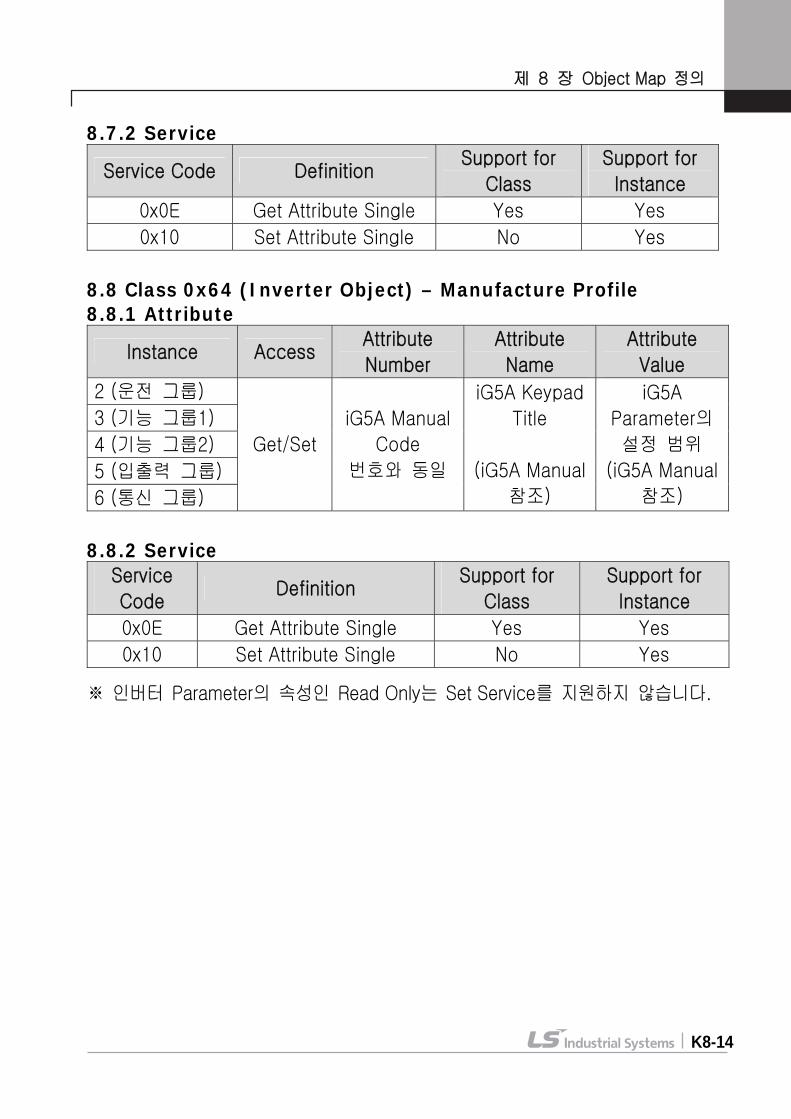
제 8 장 Object Map 정의
K8-14
8.7.2 Service
Service Code Definition Support for
Class
Support for
Instance
0x0E Get Attribute Single Yes Yes
0x10 Set Attribute Single No Yes
8.8 Class 0x64 (Inverter Object) – Manufacture Profile 8.8.1 Attribute
Instance Access Attribute
Number
Attribute
Name
Attribute
Value
2 (운전 그룹)
3 (기능 그룹1)
4 (기능 그룹2)
5 (입출력 그룹)
6 (통신 그룹)
Get/Set
iG5A Manual
Code
번호와 동일
iG5A Keypad
Title
(iG5A Manual
참조)
iG5A
Parameter의
설정 범위
(iG5A Manual
참조)
8.8.2 Service Service
Code Definition
Support for
Class
Support for
Instance
0x0E Get Attribute Single Yes Yes
0x10 Set Attribute Single No Yes ※ 인버터 Parameter의 속성인 Read Only는 Set Service를 지원하지 않습니다.
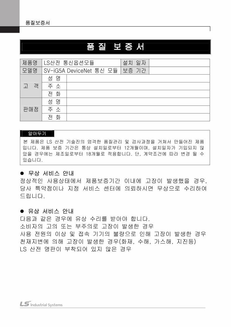
품질보증서
품 질 보 증 서
제품명 LS산전 통신옵션모듈 설치 일자
모델명 SV-iG5A DeviceNet 통신 모듈 보증 기간
성 명
주 소 고 객
전 화
성 명
주 소 판매점
전 화
알아두기
본 제품은 LS 산전 기술진의 엄격한 품질관리 및 검사과정을 거쳐서 만들어진 제품
입니다. 제품 보증 기간은 통상 설치일로부터 12개월이며, 설치일자가 기입되지 않
았을 경우에는 제조일로부터 18개월로 적용합니다. 단, 계약조건에 따라 변경 될 수
있습니다.
무상 서비스 안내
정상적인 사용상태에서 제품보증기간 이내에 고장이 발생했을 경우,
당사 특약점이나 지정 서비스 센터에 의뢰하시면 무상으로 수리하여
드립니다.
유상 서비스 안내
다음과 같은 경우에 유상 수리를 받아야 합니다.
소비자의 고의 또는 부주의로 고장이 발생한 경우
사용 전원의 이상 및 접속 기기의 불량으로 인해 고장이 발생한 경우
천재지변에 의해 고장이 발생한 경우(화재, 수해, 가스해, 지진등)
LS 산전 명판이 부착되어 있지 않은 경우