Embed Size (px)
Citation preview

Test Report issued under the responsibility of:
TEST REPORT IEC 60335-2-15
Safety of household and similar electrical appliances Part 2: Particular requirements for appliances for heating liquids
Report Number. .............................. : 18075570 701
Date of issue ................................... : 2017.09.20
Total number of pages .................. : 107
Applicant’s name ........................... : LianJiang Ricco Electrical Appliance Co.,Ltd.
Address ........................................... : No.103 Lianji north Road, Economic Development Zone, Lianjiang, Guangdong 524400 P.R. China
Test specification:
Standard ......................................... : IEC 60335-2-15:2012 (Sixth edition) in conjunction with
IEC 60335-1:2010 (Fifth edition)
Test procedure ............................... : CB Scheme
Non-standard test method………..: N/A
Test Report Form No. .................... : IEC60335_2_15J
Test Report Form(s) Originator .... : IMQ S.p.A.
Master TRF ..................................... : Dated 2017-09
Copyright © 2013 Worldwide System for Conformity Testing and Certification of Electrotechnical Equipment and Components (IECEE), Geneva, Switzerland. All rights reserved.
This publication may be reproduced in whole or in part for non-commercial purposes as long as the IECEE is acknowledged as copyright owner and source of the material. IECEE takes no responsibility for and will not assume liability for damages resulting from the reader's interpretation of the reproduced material due to its placement and context.
If this Test Report Form is used by non-IECEE members, the IECEE/IEC logo and the reference to the CB Scheme procedure shall be removed.
This report is not valid as a CB Test Report unless signed by an approved CB Testing Laboratory and appended to a CB Test Certificate issued by an NCB in accordance with IECEE 02.
Test item description ..................... : Rice Cooker Hometech 1.8L
Trade Mark ...................................... : HOMETECH
Manufacturer .................................. : LianJiang Ricco Electrical Appliance Co.,Ltd.
No.103 Lianji north Road, Economic Development Zone, Lianjiang, Guangdong 524400 P.R. China
Model/Type reference .................... : See the table A on page 6 to page 8
Ratings ............................................ : See the table A on page 6 to page 8
Report No. 18075570 701

Page 2 of 107 Report No. 18075570 701 Report No. 16075570 001
IEC60335_2_15J
Testing procedure and testing location:
CB Testing Laboratory: TÜV Rheinland (Guangdong) Ltd.
Testing location/ address........................ : No.199 Kezhu Road, Science City, Guangzhou Development Zone, Luogang District, Guangzhou, Guangdong, China,
Associated CB Testing Laboratory:
Testing location/ address........................ :
Tested by (name + signature) ........... : Elly Han
Approved by (name + signature) ..... : Louis Chen
Testing procedure: TMP
Testing location/ address........................ :
Tested by (name + signature) ........... :
Approved by (name + signature) ..... :
Testing procedure: WMT
Testing location/ address........................ :
Tested by (name + signature) ........... :
Witnessed by (name + signature) .... :
Approved by (name + signature) ..... :
Testing procedure: SMT
Testing location/ address........................ :
Tested by (name + signature) ........... :
Approved by (name + signature) ..... :
Supervised by (name + signature) ... :

Page 3 of 107 Report No. 16075570 001
IEC60335_2_15J
List of Attachments (including a total number of pages in each attachment):
Summary of testing:
Tests performed (name of test and test clause):
1. The samples were tested and found to becomplied with the requirements of standardslisted on cover page.
2. The appliance complied with the requirement ofthe standards.
Testing location:
TÜV Rheinland (Guangdong) Ltd.
No.199 Kezhu Road, Science City, Guangzhou Development Zone, Luogang District, Guangzhou, Guangdong, China,
Summary of compliance with National Differences
List of countries addressed:
EC;
EC=Ecuador
For Ecuador, there are no National differences for IEC 60335-1:2010 (Fifth Edition) and IEC 60335-2-15: 2012 (Sixth edition).
Report No. 18075570 701

Page 4 of 107 Report No. 16075570 001
IEC60335_2_15J
Copy of marking plate
The artwork below may be only a draft. The use of certification marks on a product must be authorized by the respective NCBs that own these marks.
Remark: rating label of trade mark are same as rating label of trade mark ricco except different model name and trade mark, please refer to table A on page 6 to page 8 for details.
Report No. 18075570 701

Page 5 of 107 Report No. 16075570 001
IEC60335_2_15J
Test item particulars .................................................. : Rice Cooker Hometech 1.8L
Classification of installation and use ...................... : Portable appliance
Supply Connection .................................................... : Appliance inlet / Fixed power cord with type Y
...................................................................................... :
Possible test case verdicts:
- test case does not apply to the test object ........... : N/A
- test object does meet the requirement .................. : P (Pass)
- test object does not meet the requirement ........... : F (Fail)
Testing .......................................................................... :
Date of receipt of test item ......................................... : 2017.09.03
Date (s) of performance of tests ............................... : 2017.09.03 to 2017.09.15
General remarks:
The test results presented in this report relate only to the object tested.
This report shall not be reproduced, except in full, without the written approval of the Issuing testing
laboratory.
"(See Enclosure #)" refers to additional information appended to the report.
"(See appended table)" refers to a table appended to the report.
Throughout this report a comma / point is used as the decimal separator.
Manufacturer’s Declaration per sub-clause 4.2.5 of IECEE 02:
The application for obtaining a CB Test Certificate
includes more than one factory location and a
declaration from the Manufacturer stating that the
sample(s) submitted for evaluation is (are)
representative of the products from each factory has
been provided ................................................................ :
Yes
Not applicable
When differences exist; they shall be identified in the General product information section.
Name and address of factory (ies) .......................... : LianJiang Ricco Electrical Appliance Co.,Ltd.
No.103 Lianji north Road, Economic Development Zone, Lianjiang, Guangdong 524400 P.R. China
Report No. 18075570 701

Page 6 of 107 Report No. 16075570 001
IEC60335_2_15J
General product information:
1. These class I appliances are household and indoor use only.
2. For the differences, please refer to below table A for details.
Table A;
Model
Rated
voltage(V)
Frequency
(Hz) Rated power
input(W)
Rated
volume(L) Switch type
Power supply connection
Keep warm heater
Control panel
RC Series
RC-30WP 110 60 200 0.3 W P No 7
RC-30WA 110 60 200 0.3 W A No 7
RC-60MP-CX 110 60 350 0.6 M P Yes 1,2,3,4,5,6,8,9
RC-60MA-CX 110 60 350 0.6 M A Yes 1,2,3,4,5,6,8,9
RC-60WP-CX 110 60 350 0.6 W P Yes 1,2,3,4,5,6,8,9
RC-60WA-CX 110 60 350 0.6 W A Yes 1,2,3,4,5,6,8,9
RC-100MP-CX 110 60 400 1.0 M P Yes 1,2,3,4,5,6,8,9
RC-100MA-CX 110 60 400 1.0 M A Yes 1,2,3,4,5,6,8,9
RC-100WP-CX 110 60 400 1.0 W P Yes 1,2,3,4,5,6,8,9
RC-100WA-CX 110 60 400 1.0 W A Yes 1,2,3,4,5,6,8,9
RC-150MP-CX 110 60 500 1.5 M P Yes 1,2,3,4,5,6,8,9
RC-150MA-CX 110 60 500 1.5 M A Yes 1,2,3,4,5,6,8,9
RC-150WP-CX 110 60 500 1.5 W P Yes 1,2,3,4,5,6,8,9
RC-150WA-CX 110 60 500 1.5 W A Yes 1,2,3,4,5,6,8,9
RC-180T 110 60 700 1.8 M P Yes 1,2,3,4,5,6,8,9
RC-180MA-CX 110 60 700 1.8 M A Yes 1,2,3,4,5,6,8,9
RC-180WP-CX 110 60 700 1.8 W P Yes 1,2,3,4,5,6,8,9
Report No. 18075570 701

Page 7 of 107 Report No. 16075570 001
IEC60335_2_15J
RC-180WA-CX 110 60 700 1.8 W A Yes 1,2,3,4,5,6,8,9
RC-220MP-CX 110 60 900 2.2 M P Yes 1,2,3,4,5,6,8,9
RC-220MA-CX 110 60 900 2.2 M A Yes 1,2,3,4,5,6,8,9
RC-220WP-CX 110 60 900 2.2 W P Yes 1,2,3,4,5,6,8,9
RC-220WA-CX 110 60 900 2.2 W A Yes 1,2,3,4,5,6,8,9
RC-280MP-CX 110 60 1000 2.8 M P Yes 1,2,3,4,5,6,8,9
RC-280MA-CX 110 60 1000 2.8 M A Yes 1,2,3,4,5,6,8,9
RC-280WP-CX 110 60 1000 2.8 W P Yes 1,2,3,4,5,6,8,9
RC-280WA-CX 110 60 1000 2.8 W A Yes 1,2,3,4,5,6,8,9
SRC Series
SRC-60MP-CX 110 60 350 0.6 M P Yes 2,3,4,5,6,7,9,11
SRC-60MA-CX 110 60 350 0.6 M A Yes 2,3,4,5,6,7,9,11
SRC-60WP-CX 110 60 350 0.6 W P Yes 2,3,4,5,6,7,9,11
SRC-60WA-CX 110 60 350 0.6 W A Yes 2,3,4,5,6,7,9,11
SRC-100MP-CX 110 60 400 1.0 M P Yes 2,3,4,5,6,7,9,11
SRC-100MA-CX 110 60 400 1.0 M A Yes 2,3,4,5,6,7,9,11
SRC-100WP-CX 110 60 400 1.0 W P Yes 2,3,4,5,6,7,9,11
SRC-100WA-CX 110 60 400 1.0 W A Yes 2,3,4,5,6,7,9,11
SRC-150MP-CX 110 60 500 1.5 M P Yes 1,2,3,4,5,6,7,9,10,11
SRC-150MA-CX 110 60 500 1.5 M A Yes 1,2,3,4,5,6,7,9,10,11
SRC-150WP-CX 110 60 500 1.5 W P Yes 1,2,3,4,5,6,7,9,10,11
SRC-150WA-CX 110 60 500 1.5 W A Yes 1,2,3,4,5,6,7,9,10,11
SRC-180MP-CX 110 60 700 1.8 M P Yes 1,2,3,4,5,6,7,9,10,11
SRC-180MA-CX 110 60 700 1.8 M A Yes 1,2,3,4,5,6,7,9,10,11
SRC-180Q 110 60 700 1.8 W P Yes 1,2,3,4,5,6,7,9,10,11
SRC-180WA-CX 110 60 700 1.8 W A Yes 1,2,3,4,5,6,7,9,10,11
SRC-220MP-CX 110 60 900 2.2 M P Yes 1,2,3,6,7,8,9,10,11
SRC-220MA-CX 110 60 900 2.2 M A Yes 1,2,3,6,7,8,9,10,11
Report No. 18075570 701

Page 8 of 107 Report No. 16075570 001
IEC60335_2_15J
SRC-220WP-CX 110 60 900 2.2 W P Yes 1,2,3,6,7,8,9,10,11
SRC-220WA-CX 110 60 900 2.2 W A Yes 1,2,3,6,7,8,9,10,11
SRC-280MP-CX 110 60 1000 2.8 M P Yes 1,2,3,6,7,8,9,10,11
SRC-280MA-CX 110 60 1000 2.8 M A Yes 1,2,3,6,7,8,9,10,11
SRC-280WP-CX 110 60 1000 2.8 W P Yes 1,2,3,6,7,8,9,10,11
SRC-280WA-CX 110 60 1000 2.8 W A Yes 1,2,3,6,7,8,9,10,11
Remark:
SRC series with cylindroid body. RC series with drum type body.
W---- micro swith; M---mechanical type switch;
P----power cord with type Y; A---appliance inlet and connector;
CX---control panel (X can be 1, 2, 3 etc. As listed above); for different control panel, pleas refer to photo documentation for details;
RC series and SRC series have different bottom enclosure, steamer(optional), lid and container, please refer to photo documentation for details;
OEM models with RC-60T
RC-100T
RC-150T RC-180T
RC-220T
RC-280T SRC-60Q SRC-100Q
SRC-150Q
SRC-180Q
SRC-220Q SRC-280Q
Corresponding ricco models
RC-60
MA-C1
RC-100 MA-C1
RC-150 MA-C1
RC-150 MA-C1
RC-220 MA-C1
RC-280 MA-C1
SRC-60 MA-C9
SRC-100 MA-C9
SRC-150 MA-C9
SRC-180 MA-C9
SRC-220 MA-C9
SRC-280 MA-C9
OEM models are same as ricco models except different color of appearances.
Report No. 18075570 701

Page 9 of 107
IEC 60335-2-15
Clause Requirement + Test Result - Remark Verdict
IEC60335_2_15J
5 GENERAL CONDITIONS FOR THE TESTS ---
Tests performed according to clause 5, e.g. nature of supply, sequence of testing, etc.
P
5.2 If the test of 15.101 has to be carried out, three additional samples are required (IEC 60335-2-15)
N/A
5.3 Test of 19.101, carried out after the other tests (IEC 60335-2-15)
N/A
5.101 Induction rice cookers tested as motor-operated appliances (IEC 60335-2-15)
N/A
6 CLASSIFICATION ---
6.1 Protection against electric shock: Class 0, 0I, I, II, III ...................................... ..........:
Class I P
6.2 Protection against harmful ingress of water N/A
Wash boilers and livestock feed boilers at least IPX3 (IEC 60335-2-15)
N/A
7 MARKING AND INSTRUCTIONS ---
7.1 Rated voltage or voltage range (V) ............ ..........: 110V P
Symbol for nature of supply, or .................. ..........:
Rated frequency (Hz) ................................. ..........: 60Hz P
Rated power input (W), or .......................... ..........: See table A on page 6 to page 8
P
Rated current (A) ....................................... ..........: N/A
Manufacturer's or responsible vendor's name, trademark or identification mark ................. ..........:
See rating labels on page 4 P
Model or type reference ............................. ..........: See table A on page 6 to page 8
P
Symbol IEC 60417-5172, for class II appliances N/A
IP number, other than IPX0 ........................ ..........: IP20
Symbol IEC 60417-5180, for class III appliances, unless
N/A
the appliance is operated by batteries only N/A
Symbol IEC 60417-5036, for the enclosure of electrically-operated water valves in external hose-sets for connection of an appliance to the water mains, if the working voltage exceeds extra-low voltage
N/A
N/A
P
Report No. 18075570 701

Page 10 of 107
IEC 60335-2-15
Clause Requirement + Test Result - Remark Verdict
IEC60335_2_15J
Appliances intended to be partially immersed in water for cleaning, marked with the maximum level of immersion, (IEC 60335-2-15)
N/A
And with the substance of the following: "Do not immerse beyond this level" (IEC 60335-2-15)
N/A
For kettles: level mark or other means which indicate the rated capacity (IEC 60335-2-15)
N/A
Unless they cannot be filled beyond their rated capacity (IEC 60335-2-15)
N/A
Indication visible whit kettle in filling position (IEC 60335-2-15)
N/A
Reference to the level mark on the outside of the kettle, if the level is not self-evident (IEC 60335-2-15)
N/A
Marking on the appliance of the closed position of the lid of pressure cooker, if it is not obvious (IEC 60335-2-15)
N/A
Identification mark and model or type reference of stand for cordless kettles (IEC 60335-2-15)
N/A
Soy milk makers: level mark or other means to indicate when they are filled to rated capacity (IEC 60335-2-15)
N/A
Unless they cannot be filled beyond their rated capacity (IEC 60335-2-15)
N/A
7.2 Warning for stationary appliances for multiple supply
N/A
Warning placed in vicinity of terminal cover N/A
7.3 Range of rated values marked with the lower and upper limits separated by a hyphen
N/A
Different rated values marked with the values separated by an oblique stroke
N/A
7.4 Appliances adjustable for different rated voltages, the voltage setting is clearly discernible
N/A
Requirement met if frequent changes are not required and the rated voltage to which the appliance is to be adjusted is determined from a wiring diagram
N/A
7.5 Appliances with more than one rated voltage or one or more rated voltage ranges, marked with rated input or rated current for each rated voltage or range, unless
N/A
Report No. 18075570 701

Page 11 of 107
IEC 60335-2-15
Clause Requirement + Test Result - Remark Verdict
IEC60335_2_15J
the power input is related to the arithmetic mean value of the rated voltage range
P
Relation between marking for upper and lower limits of rated power input or rated current and voltage is clear
P
7.6 Correct symbols used P
Symbol for nature of supply placed next to rated voltage
P
Symbol for class II appliances placed unlikely to be confused with other marking
N/A
Units of physical quantities and their symbols according to international standardized system
N/A
7.7 Connection diagram fixed to appliances to be connected to more than two supply conductors and appliances for multiple supply, unless
N/A
correct mode of connection is obvious N/A
7.8 Except for type Z attachment, terminals for connection to the supply mains indicated as follows:
---
- marking of terminals exclusively for the neutral conductor (letter N)
N/A
- marking of protective earthing terminals (symbol IEC 60417-5019)
P
- marking not placed on removable parts P
7.9 Marking or placing of switches which may cause a hazard
N/A
7.10 Indications of switches on stationary appliances and controls on all appliances by use of figures, letters or other visual means ...................... ..........:
By letters P
This applies also to switches which are part of a control
N/A
If figures are used, the off position indicated by the figure 0
N/A
The figure 0 indicates only OFF position, unless no confusion with the OFF position
N/A
7.11 Indication for direction of adjustment of controls N/A
7.12 Instructions for safe use provided P
Details concerning precautions during user maintenance
P
Report No. 18075570 701

Page 12 of 107
IEC 60335-2-15
Clause Requirement + Test Result - Remark Verdict
IEC60335_2_15J
The instructions state that: ---
- the appliance is not to be used by persons (including children) with reduced physical, sensory or mental capabilities, or lack of experience and knowledge, unless they have been given supervision or instruction
P
- children being supervised not to play with the appliance
P
For a part of class III construction supplied from a detachable power supply unit, the instructions state that the appliance is only to be used with the unit provided
N/A
Instructions for class III appliances state that it must only be supplied at SELV, unless
N/A
it is a battery-operated appliance, the battery being charged outside the appliance
N/A
The instructions for appliances include the substance of the following: (IEC 60335-2-15)
---
This appliance is intended to be used in household and similar applications such as: (IEC 60335-2-15)
P
- staff kitchen areas in shops, offices and other working environments;
P
- farm houses; P
- by clients in hotels, motels and other residential type environments;
P
- bed and breakfast type environments. P
If the manufacturer wants to limit the use of the appliance to less than the above, this is clearly stated in the instructions (IEC 60335-2-15)
N/A
Appliance incorporating an appliance inlet and intended to be immersed for cleaning, instructions include the following : (IEC 60335-2-15)
---
- the connector must be remove before cleaning N/A
- the appliance inlet must be dried before the appliance is used again
N/A
The instructions for appliances normally cleaned after use and not intended to be immersed in water for cleaning, state that the appliance must not be immersed (IEC 60335-2-15)
N/A
Report No. 18075570 701

Page 13 of 107
IEC 60335-2-15
Clause Requirement + Test Result - Remark Verdict
IEC60335_2_15J
This requirement normally applies to coffee-makers, cooking pans, milk heaters, pressure cookers, steam cookers, slow cookers, soy milk makers and yoghurt makers (IEC 60335-2-15)
N/A
The instructions for use for appliances intended to be used with a connector incorporating a thermostat, state that only the appropriate connector must be used (IEC 60335-2-15)
N/A
Unless, kettles are constructed so that a hazard cannot arise from boiling water being ejected, the instructions for use include the following: (IEC 60335-2-15)
---
- if the kettle is overfilled, boiling water may be ejected
N/A
The instructions for use for kettles filled through a lid aperture which is situated below the handle, include the substance of the following: (IEC 60335-2-15)
---
- WARNING: "Do not remove the lid while the water is boiling"
N/A
- WARNING: "Position the lid so that steam is directed away from the handle"
N/A
The caution statement is not required if the lid can only be closed so that steam is directed away from the handle (IEC 60335-2-15)
N/A
The instructions for cordless appliances state that the appliance is only to be used with the stand provided (IEC 60335-2-15)
N/A
If the appliance and stand of cordless appliances can be lifted together by gripping the handle of the appliance, the instructions include the substance of the following: (IEC 60335-2-15)
---
- CAUTION: Insure that the appliance is switched off before removing it from its stand.
N/A
Instructions for feeding bottle heaters: (IEC 60335-2-15) ---
- state that the food should not be heated for too long a period
N/A
- state how to check that the correct food temperature has not been exceeded
N/A
Instructions for pressure cookers, other than dynamic pressure cookers: (IEC 60335-2-15)
---
- state that the ducts in the pressure regulator allowing the escape of steam should be checked regularly to ensure that they are not blocked
N/A
Instructions for pressure cookers: (IEC 60335-2-15) ---
Report No. 18075570 701

Page 14 of 107
IEC 60335-2-15
Clause Requirement + Test Result - Remark Verdict
IEC60335_2_15J
- give details of how to open the container safely N/A
- and state that the container must not be opened until the pressure has decreased sufficiently
N/A
The instructions for use for egg boilers provided with a pricking device contain the substance of the following : (IEC 60335-2-15)
---
- CAUTION: "Avoid injuries from the egg pricking device"
N/A
Instructions for espresso coffee-makers incorporating a pressurized reservoir filled by the user: (IEC 60335-2-15)
---
- contain information for the safe refilling of the water reservoir and the substance of the following:
N/A
- WARNING: The filling aperture must not be opened during use
N/A
The instructions for all appliances include: (IEC 60335-2-15) ---
- a warning to avoid spillage on the connector P
- details on how to clean the surfaces in contact with food
P
- a warning of potential injury from misuse P
- a statement that the heating element surface is subject to residual heat after use
P
The instructions for soy milk makers also include a statement that care shall be taken when handling the sharp cutting blades, emptying the container and during cleaning (IEC 60335-2-15)
N/A
The instruction for soy milk makers incorporating a switch necessary for compliance with 22.40 include the substance of the following: (IEC 60335-2-15)
---
- Switch off the appliance and disconnect from supply before changing accessories or approaching parts that move in use
N/A
7.12.1 Sufficient details for installation supplied N/A
For an appliance intended to be permanently connected to the water mains and not connected by a hose-set, this is stated
N/A
7.12.2 Stationary appliances not fitted with means for disconnection from the supply mains having a contact separation in all poles that provide full disconnection under overvoltage category III, the instructions state that means for disconnection must be incorporated in the fixed wiring in accordance with the wiring rules
N/A
Report No. 18075570 701

Page 15 of 107
IEC 60335-2-15
Clause Requirement + Test Result - Remark Verdict
IEC60335_2_15J
7.12.3 Insulation of the fixed wiring in contact with parts exceeding 50 K during clause 11; instructions state that the fixed wiring must be protected
N/A
7.12.4 Instructions for built-in appliances: ---
- dimensions of space N/A
- dimensions and position of supporting and fixing N/A
- minimum distances between parts and surrounding structure
N/A
- minimum dimensions of ventilating openings and arrangement
N/A
- connection to supply mains and interconnection of separate components
N/A
- allow disconnection of the appliance after installation, by accessible plug or a switch in the fixed wiring, unless
N/A
a switch complying with 24.3 N/A
7.12.5 Replacement cord instructions, type X attachment with a specially prepared cord
N/A
Replacement cord instructions, type Y attachment P
Replacement cord instructions, type Z attachment N/A
7.12.6 Caution in the instructions for appliances incorporating a non-self-resetting thermal cut-out that is reset by disconnection of the supply mains, if this cut-out is required to comply with the standard
N/A
7.12.7 Instructions for fixed appliances stating how the appliance is to be fixed
N/A
7.12.8 Instructions for appliances connected to the water mains: ---
- max. inlet water pressure (Pa) ................. ..........: N/A
- min. inlet water pressure, if necessary (Pa) ........: N/A
Instructions concerning new and old hose-sets for appliances connected to the water mains by detachable hose-sets
N/A
7.13 Instructions and other texts in an official language Spanish P
7.14 Marking clearly legible and durable, rubbing test as specified
P
7.15 Markings on a main part P
Marking clearly discernible from the outside, if necessary after removal of a cover
P
Report No. 18075570 701

Page 16 of 107
IEC 60335-2-15
Clause Requirement + Test Result - Remark Verdict
IEC60335_2_15J
For portable appliances, cover can be removed or opened without a tool
N/A
For stationary appliances, name, trademark or identification mark and model or type reference visible after installation
N/A
For fixed appliances, name, trademark or identification mark and model or type reference visible after installation according to the instructions
N/A
Indications for switches and controls placed on or near the components. Marking not on parts which can be positioned or repositioned in such a way that the marking is misleading
N/A
7.16 Marking of a possible replaceable thermal link or fuse link clearly visible with regard to replacing the link
N/A
8 PROTECTION AGAINST ACCESS TO LIVE PARTS ---
8.1 Adequate protection against accidental contact with live parts
P
8.1.1 Requirement applies for all positions, detachable parts removed
P
Lamps behind a detachable cover not removed, if conditions met
N/A
Insertion or removal of lamps, protection against contact with live parts of the lamp cap
N/A
Use of test probe B of IEC 61032, with a force not exceeding 1 N: no contact with live parts
P
Use of test probe B of IEC 61032 through openings, with a force of 20N: no contact with live parts
P
8.1.2 Use of test probe 13 of IEC 61032, with a force not exceeding 1 N, through openings in class 0 appliances and class II appliances/constructions: no contact with live parts
P
Test probe 13 also applied through openings in earthed metal enclosures having a non-conductive coating: no contact with live parts
P
See Note 101 (IEC 60335-2-15) P
8.1.3 For appliances other than class II, use of test probe 41 of IEC 61032, with a force not exceeding 1 N: no contact with live parts of visible glowing heating elements
N/A
Report No. 18075570 701
Page 17 of 107
IEC 60335-2-15
Clause Requirement + Test Result - Remark Verdict
IEC60335_2_15J
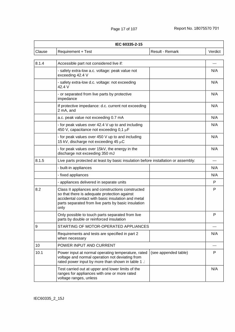
8.1.4 Accessible part not considered live if: ---
- safety extra-low a.c. voltage: peak value not exceeding 42.4 V
N/A
- safety extra-low d.c. voltage: not exceeding 42.4 V
N/A
- or separated from live parts by protective impedance
N/A
If protective impedance: d.c. current not exceeding 2 mA, and
N/A
a.c. peak value not exceeding 0.7 mA N/A
- for peak values over 42.4 V up to and including
450 V, capacitance not exceeding 0,1 F
N/A
- for peak values over 450 V up to and including
15 kV, discharge not exceeding 45 C
N/A
- for peak values over 15kV, the energy in the discharge not exceeding 350 mJ
N/A
8.1.5 Live parts protected at least by basic insulation before installation or assembly: ---
- built-in appliances N/A
- fixed appliances N/A
- appliances delivered in separate units P
8.2 Class II appliances and constructions constructed so that there is adequate protection against accidental contact with basic insulation and metal parts separated from live parts by basic insulation only
P
Only possible to touch parts separated from live parts by double or reinforced insulation
P
9 STARTING OF MOTOR-OPERATED APPLIANCES ---
Requirements and tests are specified in part 2 when necessary
N/A
10 POWER INPUT AND CURRENT ---
10.1 Power input at normal operating temperature, rated voltage and normal operation not deviating from rated power input by more than shown in table 1 .:
(see appended table) P
Test carried out at upper and lower limits of the ranges for appliances with one or more rated voltage ranges, unless
N/A
Report No. 18075570 701

Page 18 of 107
IEC 60335-2-15
Clause Requirement + Test Result - Remark Verdict
IEC60335_2_15J
the rated power input is related to the arithmetic mean value
N/A
10.2 Current at normal operating temperature, rated voltage and normal operation not deviating from rated current by more than shown in table 2 .........:
(see appended table) N/A
Test carried out at upper and lower limits of the ranges for appliances with one or more rated voltage ranges, unless
N/A
the rated current is related to the arithmetic mean value of the range
N/A
11 HEATING ---
11.1 No excessive temperatures in normal use P
11.2 The appliance is held, placed or fixed in position as described ...............................................................:
N/A
Portable appliances tested away from the walls of the test corner (IEC 60335-2-15)
P
11.3 Temperature rises, other than of windings, determined by thermocouples
P
Temperature rises of windings determined by resistance method, unless
N/A
the windings are non-uniform or it is difficult to make the necessary connections
N/A
See Note 101 (IEC 60335-2-15) N/A
11.4 Heating appliances operated under normal operation at 1.15 times rated power input (W) .....:
(see appended table) P
If the temperature rise limits are exceeded in appliances incorporating motors, transformers or electronic circuits and if the power input is lower than the rated power input, test repeated with the appliance supplied at 1,06 times rated voltage (IEC 60335-2-15)
N/A
11.5 Motor-operated appliances operated under normal operation at most unfavourable voltage between 0.94 and 1.06 times rated voltage (V) ...................:
N/A
11.6 Combined appliances operated under normal operation at most unfavourable voltage between 0.94 and 1.06 times rated voltage (V) ...................:
N/A
Combined appliances tested as heating appliances (IEC 60335-2-15)
N/A
Report No. 18075570 701

Page 19 of 107
IEC 60335-2-15
Clause Requirement + Test Result - Remark Verdict
IEC60335_2_15J
11.7 Appliances operated for the duration specified in 11.7.101 to 11.7.106 (IEC 60335-2-15)
P
11.7.101 For kettles with temperature limiter: test terminated after second operation of temperature limiter (IEC 60335-2-15)
N/A
For kettles with thermostat: test terminated 15 min after the water has attained 95 °C
N/A
For other kettles: test terminated 5 min after the water has attained 95 °C
N/A
11.7.102 For cooking pans, egg boilers, feeding-bottle heaters, glue pots, livestock feed boilers, milk heaters, sterilizers, wash boilers and for appliances that boil water other than kettles, the test is terminated: (IEC 60335-2-15)
---
- appliances without a thermal control: 15 min after the water in the container has attained a temperature of 95 °C or the maximum temperature it can attain if this is lower
N/A
- portable appliances provided with a thermal control: 15 min after the thermal control has operated for the first time
N/A
- fixed appliances provided with a thermal control: 30 min after the thermal control has operated for the first time
N/A
- appliances with acoustic signal: 1 min after signal N/A
- egg boilers having provision for keeping eggs warm, and appliances having a heated surface intended to keep liquid warm: when steady conditions are established
N/A
11.7.103 Slow cookers, rice cookers, steam cookers and yoghurt makers operated until steady conditions are established (IEC 60335-2-15)
P
Slow cookers prewarmed in the dry state if this instruction is given
N/A
11.7.104 Espresso coffee-makers operated in accordance with the instructions for use (IEC 60335-2-15)
N/A
Automatic espresso coffee makers and espresso coffee makers, the brewing period is the time necessary to produce the maximum quantity of coffee allowed by the timer or by the capacity of the coffee pot
N/A
Manual espresso coffee makers, maximum quantity of coffee to be produced specified in the instructions, or
N/A
Report No. 18075570 701

Page 20 of 107
IEC 60335-2-15
Clause Requirement + Test Result - Remark Verdict
IEC60335_2_15J
the brewing period is the time necessary to produce 100 ml of coffee for each cycle
N/A
Espresso coffee-makers having an outlet for supplying steam or hot water, the brewing period is immediately followed by a period during which the steam or water is supplied for the time stated in the instructions, or
N/A
- espresso coffee makers having an outlet for supplying steam, 1 min.
N/A
- espresso coffee makers having an outlet for supplying water, the time necessary to produce 100 ml of water
N/A
Espresso coffee-makers operated until steady conditions are established
N/A
Other coffee-makers operated for the time necessary to make the maximum quantity of coffee stated in the instructions
N/A
The container refilled as quickly as possible and the coffee-maker operated again until steady conditions are established
N/A
11.7.105 Pressure cookers operated 15 min after attaining the maximum cooking pressure (IEC 60335-2-15)
N/A
11.7.106 Soy milk makers operated for a complete operating cycle (IEC 60335-2-15)
N/A
11.8 Temperature rises monitored continuously and not exceeding the values in table 3 ............................:
(see appended table) P
If the temperature rise of a motor winding exceeds the value of table 3, or
N/A
if there is doubt with regard to classification of insulation,
N/A
tests of Annex C are carried out N/A
Sealing compound does not flow out P
Protective devices do not operate, except P
components in protective electronic circuits tested for the number of cycles specified in 24.1.4
N/A
When an appliance connector incorporates a thermostat, the temperature rise limit for the pins of the inlet does not apply (IEC 60335-2-15)
N/A
Report No. 18075570 701

Page 21 of 107
IEC 60335-2-15
Clause Requirement + Test Result - Remark Verdict
IEC60335_2_15J
The temperature rise limits of motors, transformers, components of electronic circuit and parts directly influenced by them may be exceeded when the appliance is operated at 1,15 times rated power input (IEC 60335-2-15)
N/A
13 LEAKAGE CURRENT AND ELECTRIC STRENGTH AT OPERATING TEMPERATURE
---
13.1 Leakage current not excessive and electric strength adequate
P
Heating appliances operated at 1.15 times the rated power input (W) ............................................:
(see appended table) P
Motor-operated appliances and combined appliances supplied at 1.06 times the rated voltage (V) ..........................................................................:
N/A
Protective impedance and radio interference filters disconnected before carrying out the tests
N/A
13.2 For class 0, class II and class III appliances, leakage current measured by means of the circuit described in figure 4 of IEC 60990
N/A
For other appliances, a low impedance ammeter may be used
P
Leakage current measurements ...........................: (see appended table) P
13.3 The appliance is disconnected from the supply P
Electric strength tests according to table 4 ...........: (see appended table) P
No breakdown during the tests P
14 TRANSIENT OVERVOLTAGES ---
Appliances withstand the transient over-voltages to which they may be subjected
N/A
Clearances having a value less than specified in table 16 subjected to an impulse voltage test, the test voltage specified in table 6 .............................:
(see appended table) N/A
No flashover during the test, unless N/A
of functional insulation if the appliance complies with clause 19 with the clearance short-circuited
N/A
15 MOISTURE RESISTANCE ---
15.1 Enclosure provides the degree of moisture protection according to classification of the appliance
N/A
Report No. 18075570 701

Page 22 of 107
IEC 60335-2-15
Clause Requirement + Test Result - Remark Verdict
IEC60335_2_15J
Compliance checked as specified in 15.1.1, taking into account 15.1.2, followed by the electric strength test of 16.3
N/A
No trace of water on insulation which can result in a reduction of clearances or creepage distances below values specified in clause 29
N/A
15.1.1 Appliances, other than IPX0, subjected to tests as specified in IEC 60529 ..........................................:
N/A
Water valves containing live parts in external hoses for connection of an appliance to the water mains tested as specified for IPX7 appliances
N/A
15.1.2 Hand-held appliance turned continuously through the most unfavourable positions during the test
N/A
Built-in appliances installed according to the instructions
N/A
Appliances placed or used on the floor or table placed on a horizontal unperforated support
N/A
Appliances normally fixed to a wall and appliances with pins for insertion into socket-outlets are mounted on a wooden board
N/A
For IPX3 appliances, the base of wall mounted appliances is placed at the same level as the pivot axis of the oscillating tube
N/A
For IPX4 appliances, the horizontal centre line of the appliance is aligned with the pivot axis of the oscillating tube, and
N/A
for appliances normally used on the floor or table,
the movement is limited to two times 90 for a period of 5 min, the support being placed at the level of the pivot axis of the oscillating tube
N/A
Wall-mounted appliances, take into account the distance to the floor stated in the instructions
N/A
Appliances normally fixed to a ceiling are mounted underneath a horizontal unperforated support, the pivot axis of the oscillating tube located at the level of the underside of the support, and
N/A
for IPX4 appliances, the movement of the tube is
limited to two times 90 from the vertical for a period of 5 min
N/A
Appliances with type X attachment fitted with a flexible cord as described
N/A
Report No. 18075570 701

Page 23 of 107
IEC 60335-2-15
Clause Requirement + Test Result - Remark Verdict
IEC60335_2_15J
Detachable parts subjected to the relevant treatment with the main part
N/A
However, if a part has to be removed for user maintenance and a tool is needed, this part is not removed
N/A
15.2 Spillage of liquid does not affect the electrical insulation
P
Appliances with type X attachment fitted with a flexible cord as described
N/A
Appliances incorporating an appliance inlet tested with or without an connector, whichever is most unfavourable
P
The test is only carried out with the appliance connector in position (IEC 60335-2-15)
P
For cordless appliances, the test with the appliance on the horizontal plane carried out with the appliance both on and off its stand (IEC 60335-2-15)
N/A
For rice cookers, the test carried out with the rice container in place (IEC 60335-2-15)
P
In case of doubt, spillage tests carried out with the appliance deviating from the normal position by an angle not exceeding 5° (IEC 60335-2-15)
N/A
Detachable parts are removed N/A
Overfilling test with additional amount of water, over a period of 1 min (l) ............................:
1.06L P
The appliance withstands the electric strength test of 16.3
P
No trace of water on insulation that can result in a reduction of clearances or creepage distances below values specified in clause 29
P
Kettles that can be filled through the spout: additional overfilling test in conditions as specified (IEC 60335-2-15)
N/A
For cordless kettles, the additional test carried out only with the cordless kettle off its stand, the kettle being replaced on its stand in order to carry out the electric strength test of 16.3 (IEC 60335-2-15)
N/A
Coffee makers provided with a removable coffee pot: particular overfilling test in conditions as specified (IEC 60335-2-15)
N/A
Report No. 18075570 701

Page 24 of 107
IEC 60335-2-15
Clause Requirement + Test Result - Remark Verdict
IEC60335_2_15J
Steam sterilizers: particular overfilling test in conditions as specified (IEC 60335-2-15)
N/A
15.3 Appliances proof against humid conditions P
Checked by test Cab: Damp heat steady state in IEC 60068-2-78
P
Detachable parts removed and subjected, if necessary, to the humidity test with the main part
P
Humidity test for 48 h in a humidity cabinet P
Reassembly of those parts that may have been removed
P
The appliance withstands the tests of clause 16 P
15.101 Appliances to be partially or completely immersed in water for cleaning sufficiently protected against effects of immersion (IEC 60335-2-15)
N/A
Compliance is checked by the tests as specified, which are carried out on three additional appliances
N/A
No trace of water on insulation which can result in reduction of creepage distances and clearance below values specified in 29
N/A
15.102 Connecting device of stands for cordless kettles not affected by water : particular electric strength test in conditions as specified (IEC 60335-2-15)
N/A
Compliance is checked by the test in conditions as specified
N/A
Stand withstanding the test of 16.3 with voltage reduced to 2500 V for reinforced insulation
N/A
15.103 Interior of rice cookers not affected by water (IEC 60335-2-15)
P
Compliance is checked by the test as specified P
Rice cookers withstanding the electric strength test of 16.3
P
16 LEAKAGE CURRENT AND ELECTRIC STRENGTH ---
16.1 Leakage current not excessive and electric strength adequate
P
Protective impedance disconnected from live parts before carrying out the tests
P
Tests carried out at room temperature and not connected to the supply
P
Report No. 18075570 701

Page 25 of 107
IEC 60335-2-15
Clause Requirement + Test Result - Remark Verdict
IEC60335_2_15J
16.2 Single-phase appliances: test voltage 1.06 times rated voltage (V) ....................................................:
(see appended table) P
Three-phase appliances: test voltage 1.06 times
rated voltage divided by 3 (V) .............................:
N/A
Leakage current measurements ...........................: (see appended table) P
Limit values doubled if: ---
- all controls have an off position in all poles, or N/A
- the appliance has no control other than a thermal cut-out, or
N/A
- all thermostats, temperature limiters and energy regulators do not have an off position, or
N/A
- the appliance has radio interference filters N/A
With the radio interference filters disconnected, the leakage current do not exceed limits specified .....:
(see appended table) N/A
16.3 Electric strength tests according to table 7 ...........: (see appended table) P
Test voltage applied between the supply cord and inlet bushing and cord guard and cord anchorage as specified ...........................................................:
(see appended table) P
No breakdown during the tests P
17 OVERLOAD PROTECTION OF TRANSFORMERS AND ASSOCIATED CIRCUITS ---
No excessive temperatures in transformer or associated circuits in event of short-circuits likely to occur in normal use ...............................................:
(see appended table) N/A
Appliance supplied with 1.06 or 0.94 times rated voltage under the most unfavourable short-circuit or overload likely to occur in normal use (V) .............:
N/A
Basic insulation is not short-circuited N/A
Temperature rise of insulation of the conductors of safety extra-low voltage circuits not exceeding the relevant value specified in table 3 by more than 15 K
N/A
Temperature of the winding not exceeding the value specified in table 8
N/A
However, limits do not apply to fail-safe transformers complying with sub-clause 15.5 of IEC 61558-1
N/A
18 ENDURANCE ---
Report No. 18075570 701

Page 26 of 107
IEC 60335-2-15
Clause Requirement + Test Result - Remark Verdict
IEC60335_2_15J
Requirements and tests are specified in part 2 when necessary
N/A
19 ABNORMAL OPERATION ---
19.1 The risk of fire, mechanical damage or electric shock under abnormal or careless operation obviated
P
Electronic circuits so designed and applied that a fault will not render the appliance unsafe .............:
(see appended table) N/A
Appliances incorporating heating elements subjected to the tests of 19.2 and 19.3, and
P
if the appliance also has a control that limit the temperature during clause 11 it is subjected to the test of 19.4, and
P
if applicable, to the test of 19.5 P
Appliances incorporating PTC heating elements are also subjected to the test of 19.6
N/A
Appliances incorporating motors subjected to the tests of 19.7 to 19.10, as applicable
N/A
Appliances incorporating electronic circuits subjected to the tests of 19.11 and 19.12, as applicable
N/A
Appliances incorporating contactors or relays subjected to the test of 19.14, being carried out before the tests of 19.11
N/A
Appliances incorporating voltage selector switches subjected to the test of 19.15
N/A
Unless otherwise specified, the tests are continued until a non-self-resetting thermal cut-out operates, or
P
until steady conditions are established P
If a heating element or intentionally weak part becomes open-circuited, the relevant test is repeated on a second sample
N/A
Kettles are not subjected to the test of 19.2 (IEC 60335-2-15)
N/A
Kettles also subjected to the test of 19.101, unless the appliance incorporates a non-self-resetting thermal cut-out, in order to comply with 19.4 (IEC 60335-2-15)
N/A
Report No. 18075570 701

Page 27 of 107
IEC 60335-2-15
Clause Requirement + Test Result - Remark Verdict
IEC60335_2_15J
Kettles for which compliance with 19.101 relies on the operation of a non-self-resetting thermal cut-out are subjected to the test of 19.102 (IEC 60335-2-15)
N/A
19.2 Test of appliances with heating elements with restricted heat dissipation; test voltage (V), power input of 0.85 times rated power input (W) .............:
(See appended table) P
Appliances are placed as near as possible to the walls of the test corner (IEC 60335-2-15)
P
They are tested empty with lids open or closed whichever is the more unfavourable (IEC 60335-2-15)
P
Induction rice cookers operating under the conditions of clause 11 with the rice container empty (IEC 60335-2-15)
N/A
19.3 Test of 19.2 repeated; test voltage (V), power input of 1.24 times rated power input (W) ......................:
(See appended table) P
Kettles are operated empty at 1.15 times rated power input (IEC 60335-2-15)
N/A
The test is carried out with the kettle filled with sufficient water to cover the heating element or if the heating element is not positioned inside the container, to a depth of 10 mm (IEC 60335-2-15)
N/A
19.4 Test conditions as in clause 11, any control limiting the temperature during tests of clause 11 short-circuited
P
Pressure cookers: (IEC 60335-2-15) ---
- all pressure regulating devices rendered inoperative; and
N/A
- in other than dynamic pressure cookers, all protective devices that vent steam and intentionally weak parts that vent steam rendered inoperative; and
N/A
- in dynamic pressure cookers, all protective devices, other than intentionally weak parts, that vent steam rendered inoperative
N/A
19.5 Test of 19.4 repeated on Class 0I and I appliances with tubular sheathed or embedded heating elements. No short-circuiting, but one end of the element connected to the sheath
P
Report No. 18075570 701

Page 28 of 107
IEC 60335-2-15
Clause Requirement + Test Result - Remark Verdict
IEC60335_2_15J
The test repeated with reversed polarity and the other end of the heating element connected to the sheath
P
The test is not carried out on appliances intended to be permanently connected to fixed wiring and on appliances where an all-pole disconnection occurs during the test of 19.4
N/A
19.6 Appliances with PTC heating elements tested at rated voltage, establishing steady conditions
N/A
The working voltage of the PTC heating element is increased by 5% and the appliance is operated until steady conditions are re-established. The voltage is then increased in similar steps until 1.5 times working voltage or until the PTC heating element ruptures (V) ...........................................................:
N/A
19.7 Stalling test by locking the rotor if the locked rotor torque is smaller than the full load torque, or
N/A
locking moving parts of other appliances N/A
Locked rotor, capacitors open-circuited one at a time
N/A
Test repeated with capacitors short-circuited one at a time, unless
N/A
capacitor is of class P2 of IEC 60252-1 N/A
Appliances with timer or programmer supplied with rated voltage for each of the tests, for a period equal to the maximum period allowed ...................:
N/A
Other appliances supplied with rated voltage for a period as specified ................................................:
N/A
Espresso coffee-makers incorporating a pump operated for a period of 5 min (IEC 60335-2-15)
N/A
Soy milk makers operated for one cycle of operation (IEC 60335-2-15)
N/A
Winding temperatures not exceeding values specified in table 8 .................................................:
(see appended table) N/A
19.8 Multi-phase motors operated at rated voltage with one phase disconnected
N/A
19.9 Running overload test on appliances incorporating motors intended to be remotely or automatically controlled or liable to be operated continuously
N/A
Report No. 18075570 701

Page 29 of 107
IEC 60335-2-15
Clause Requirement + Test Result - Remark Verdict
IEC60335_2_15J
Motor-operated and combined appliances for which 30.2.3 is applicable and that use overload protective devices relying on electronic circuits to protect the motor windings, are also subjected to the test
N/A
Winding temperatures not exceeding values as specified ................................................................:
(see appended table) N/A
19.10 Series motor operated at 1.3 times rated voltage for 1 min (V) ................................................................:
N/A
During the test, parts not being ejected from the appliance
N/A
19.11 Electronic circuits, compliance checked by evaluation of the fault conditions specified in 19.11.2 for all circuits or parts of circuits, unless
N/A
they comply with the conditions specified in 19.11.1 N/A
Appliances incorporating an electronic circuit that relies upon a programmable component to function correctly, subjected to the test of 19.11.4.8, unless
N/A
restarting does not result in a hazard N/A
Appliances having a device with an off position obtained by electronic disconnection, or a device placing the appliance in a stand-by mode, subjected to the tests of 19.11.4
N/A
If the safety of the appliance under any of the fault conditions depends on the operation of a miniature fuse-link complying with IEC 60127, the test of 19.12 is carried out
N/A
During and after each test the following is checked: ---
- the temperature of the windings do not exceed the values specified in table 8
N/A
- the appliance complies with the conditions specified in 19.13
N/A
- any current flowing through protective impedance not exceeding the limits specified in 8.1.4
N/A
If a conductor of a printed board becomes open-circuited, the appliance is considered to have withstood the particular test, provided both of the following conditions are met:
---
- the base material of the printed circuit board withstands the test of Annex E
N/A
Report No. 18075570 701

Page 30 of 107
IEC 60335-2-15
Clause Requirement + Test Result - Remark Verdict
IEC60335_2_15J
- any loosened conductor does not reduce clearance or creepage distances between live parts and accessible metal parts below the values specified in clause 29
P
19.11.1 Fault conditions a) to g) in 19.11.2 are not applied to circuits or parts of circuits meeting both of the following conditions:
---
- the electronic circuit is a low-power circuit, that is, the maximum power at low-power points does not exceed 15 W according to the tests specified
N/A
- the protection against electric shock, fire hazard, mechanical hazard or dangerous malfunction of other parts of the appliance does not rely on the correct functioning of the electronic circuit
N/A
19.11.2 Fault conditions applied one at a time, the appliance operating under conditions specified in clause 11, but supplied at rated voltage, duration of the tests as specified:
---
a) short circuit of functional insulation if clearancesor creepage distances are less than the values specified in clause 29
N/A
b) open circuit at the terminals of any component N/A
c) short circuit of capacitors, unless N/A
they comply with IEC 60384-14 N/A
d) short circuit of any two terminals of an electroniccomponent, other than integrated circuits
N/A
This fault condition is not applied between the two circuits of an optocoupler
N/A
e) failure of triacs in the diode mode N/A
f) failure of microprocessors and integrated circuits N/A
g) failure of an electronic power switching device N/A
Each low power circuit is short-circuited by connecting the low-power point to the pole of the supply source from which the measurements were made
N/A
19.11.3 If the appliance incorporates a protective electronic circuit which operates to ensure compliance with clause 19, the relevant test is repeated with a single fault simulated, as indicated in a) to g) of 19.11.2
N/A
19.11.4 Appliances having a device with an off position obtained by electronic disconnection, or
N/A
Report No. 18075570 701

Page 31 of 107
IEC 60335-2-15
Clause Requirement + Test Result - Remark Verdict
IEC60335_2_15J
a device that can be placed in the stand-by mode, N/A
subjected to the tests of 19.11.4.1 to 19.11.4.7, the device being set in the off position or in the stand-by mode
N/A
Appliances incorporating a protective electronic circuit subjected to the tests of 19.11.4.1 to 19.11.4.7, the tests being carried out after the protective electronic circuit has operated, except that
N/A
appliances operated for 30 s or 5 min during the test of 19.7 are not subjected to the tests for electromagnetic phenomena.
N/A
Surge protective devices disconnected, unless N/A
They incorporate spark gaps N/A
19.11.4.1 The appliance is subjected to electrostatic discharges in accordance with IEC 61000-4-2, test level 4
N/A
19.11.4.2 The appliance is subjected to radiated fields in accordance with IEC 61000-4-3, test level 3
N/A
19.11.4.3 The appliance is subjected to fast transient bursts in accordance with IEC 61000-4-4, test level 3 or 4 as specified
N/A
19.11.4.4 The power supply terminals of the appliance subjected to voltage surges in accordance with IEC 61000-4-5, test level 3 or 4 as specified
N/A
Earthed heating elements in class I appliances disconnected
N/A
19.11.4.5 The appliance is subjected to injected currents in accordance with IEC 61000-4-6, test level 3
N/A
19.11.4.6 Appliances having a rated current not exceeding 16 A are subjected to the Class 3 voltage dips and interruptions in accordance with IEC 61000-4-11
N/A
Appliances having a rated current exceeding 16 A are subjected to the Class 3 voltage dips and interruptions in accordance with IEC 61000-4-34
N/A
19.11.4.7 The appliance is subjected to mains signals in accordance with IEC 61000-4-13, test level class 2
N/A
Report No. 18075570 701

Page 32 of 107
IEC 60335-2-15
Clause Requirement + Test Result - Remark Verdict
IEC60335_2_15J
19.11.4.8 The appliance is supplied at rated voltage and operated under normal operation. After 60s the power supply is reduced to a level such that the appliance ceases to respond or parts controlled by the programmable component cease to operate
N/A
The appliance continues to operate normally, or N/A
requires a manual operation to restart N/A
19.12 If the safety of the appliance for any of the fault conditions specified in 19.11.2 depends on the operation of a miniature fuse-link complying with IEC 60127, the test is repeated, measuring the current flowing through the fuse-link; measured current (A); rated current of the fuse-link (A).........:
N/A
19.13 During the tests the appliance does not emit flames, molten metal, poisonous or ignitable gas in hazardous amounts
P
Temperature rises not exceeding the values shown in table 9 ................................................................:
(see appended table) P
Compliance with clause 8 not impaired P
If the appliance can still be operated it complies with 20.2
N/A
Insulation, other than of class III appliances or class III constructions that do not contain live parts, withstands the electric strength test of 16.3, the test voltage as specified in table 4:
---
- basic insulation (V) ..............................................: 1000V P
- supplementary insulation (V) ..............................: N/A
- reinforced insulation (V) ......................................: 2500V P
After operation or interruption of a control, clearances and creepage distances across the functional insulation withstand the electric strength test of 16.3, the test voltage being twice the working voltage
N/A
The appliance does not undergo a dangerous malfunction, and
N/A
no failure of protective electronic circuits, if the appliance is still operable
N/A
Appliances tested with an electronic switch in the off position, or in the stand-by mode:
---
- do not become operational, or N/A
Report No. 18075570 701

Page 33 of 107
IEC 60335-2-15
Clause Requirement + Test Result - Remark Verdict
IEC60335_2_15J
- if they become operational, do not result in a dangerous malfunction during or after the tests of 19.11.4
N/A
If the appliance contains lids or doors that are controlled by one or more interlocks, one of the interlocks may be released provided that:
---
- the lid or door does not move automatically to an open position when the interlock is released, and
N/A
- the appliance does not start after the cycle in which the interlock was released
N/A
During the test of 19.4, protective devices of pressure cookers other than dynamic pressure cookers operate before pressure has reached 350 kPa (IEC 60335-2-15)
N/A
During the test of 19.4, protective devices or intentionally weak parts of dynamic pressure cookers operate before pressure has reached 250 kPa (IEC 60335-2-15)
N/A
Temperature rise of windings of induction rice cookers not exceeding the values specified in 19.7 (IEC 60335-2-15)
N/A
Induction rice cookers: electric strength test carried out immediately after switching off the appliance (IEC 60335-2-15)
N/A
19.14 Appliances operated under the conditions of clause 11, any contactor or relay contact operating under the conditions of clause 11 being short-circuited
N/A
For a relay or contactor with more than one contact, all contacts are short-circuited at the same time
N/A
A relay or contactor operating only to ensure the appliance is energized for normal use is not short-circuited
N/A
If more than one relay or contactor operates in clause 11, they are short-circuited in turn
N/A
19.15 For appliances with a mains voltage selector switch, the switch is set to the lowest rated voltage position and the highest value of rated voltage is applied
N/A
19.101 Kettles operated empty at 0,85 times or 1,15 times rated power input, whichever is more unfavourable, with thermal cut-out that operates during the test of 19.4 short circuited (IEC 60335-2-15)
N/A
Report No. 18075570 701

Page 34 of 107
IEC 60335-2-15
Clause Requirement + Test Result - Remark Verdict
IEC60335_2_15J
During the test, any flames keep within the enclosure of the kettle and supporting surface does not ignite
N/A
After the test, live parts not be accessible N/A
19.102 Kettles incorporating two self-resetting thermal cut-outs operated with one of the thermal cut-out short circuited, empty at 0.85 or 1.15 times rated power input, whichever is most unfavourable (IEC 60335-2-15)
N/A
Within 2 s of the thermal cut-out operating, the kettle is filled with water having a temperature of 15 °C ± 5 °C. After 1 min, the kettle is emptied
N/A
The test is carried out 100 times N/A
19.103 Appliances with detachable liquid containers: automatic transfer of liquid from one container to another is liable and safe (IEC 60335-2-15)
N/A
Compliance is checked by the test as specified N/A
After the test, the appliance withstands the tests of 16.3 and
N/A
no trace of water on insulation which can result in reduction of creepage distances and clearances below values specified in clause 29
N/A
19.104 The overloading of a soy milk maker does not result in a hazard (IEC 60335-2-15)
N/A
Compliance is checked by the test as specified N/A
During the test, any flames keep within the enclosure and supporting surface does not ignite
N/A
After the test, live parts not be accessible N/A
19.105 When a soy milk maker is disconnected from the supply accidently during normal use, it does not result in a hazard (IEC 60335-2-15)
N/A
Compliance is checked by the test as specified N/A
During the test, any flames keep within the enclosure and supporting surface does not ignite
N/A
After the test, live parts not be accessible N/A
20 STABILITY AND MECHANICAL HAZARDS ---
20.1 Appliances having adequate stability P
Report No. 18075570 701

Page 35 of 107
IEC 60335-2-15
Clause Requirement + Test Result - Remark Verdict
IEC60335_2_15J
Tilting test through an angle of 10, appliance placed on an inclined plane/horizontal support, not connected to the supply mains; appliance does not overturn
P
Tilting test repeated on appliances with heating
elements, angle of inclination increased to 15
P
Possible heating test in overturned position; temperature rise does not exceed values shown in table 9
N/A
20.2 Moving parts adequately arranged or enclosed as to provide protection against personal injury
N/A
Protective enclosures, guards and similar parts are non-detachable, and
N/A
have adequate mechanical strength N/A
Enclosures that can be opened by overriding an interlock are considered to be detachable parts
N/A
Self-resetting thermal cut-outs and overcurrent protective devices not causing a hazard by unexpected closure
N/A
Not possible to touch dangerous moving parts with the test probe described
N/A
20.101 The container and cutting blades of soy milk makers have adequate mechanical strength (IEC 60335-2-15)
N/A
Compliance is checked by the test as specified N/A
Container and cutting blades not broken N/A
20.102 The rotating parts of soy milk makers not become loose during operation (IEC 60335-2-15)
N/A
Compliance is checked by inspection and manual test as specified
N/A
Fastening of screws and nuts in a direction opposite to the direction of rotation of the rotating parts considered to be a suitable means of securing the rotating parts
N/A
20.103 For soy milk makers: lid interlock, if any, constructed so that accidental operation of the appliance is prevented (IEC 60335-2-15)
N/A
Lid interlock switches are biased-off switches N/A
Report No. 18075570 701

Page 36 of 107
IEC 60335-2-15
Clause Requirement + Test Result - Remark Verdict
IEC60335_2_15J
If there is an interlock between the lid and the main switch, the lid is locked when the switch is in the on position
N/A
When the lid is not correctly closed, the switch is locked in the off position
N/A
Compliance is checked by inspection, by manual test and by applying test probe B of IEC 61032
N/A
21 MECHANICAL STRENGTH ---
21.1 Appliance has adequate mechanical strength and is constructed as to withstand rough handling
P
Checked by applying 3 blows to every point of the enclosure like to be weak, in accordance with test Ehb of IEC 60068-2-75, spring hammer test, with an impact energy of 0,5 J
P
The appliance shows no damage impairing compliance with this standard, and
P
compliance with 8.1, 15.1 and clause 29 not impaired
P
If doubt, supplementary or reinforced insulation subjected to the electric strength test of 16.3
N/A
If necessary, repetition of groups of three blows on a new sample
N/A
Breakage of glass parts is neglected provided that compliance with 8.1, 15.1 and 15.101 is not impaired (IEC 60335-2-15)
N/A
21.2 Accessible parts of solid insulation having strength to prevent penetration by sharp implements
P
Test not applicable if the thickness of supplementary insulation is at least 1 mm and reinforced insulation at least 2 mm
P
The insulation is tested as specified, and does withstand the electric strength test of 16.3
N/A
22 CONSTRUCTION ---
22.1 Appliance marked with the first numeral of the IP system, relevant requirements of IEC 60529 are fulfilled
N/A
22.2 Stationary appliance: means to ensure all-pole disconnection from the supply being provided:
---
- a supply cord fitted with a plug, or N/A
- a switch complying with 24.3, or N/A
Report No. 18075570 701

Page 37 of 107
IEC 60335-2-15
Clause Requirement + Test Result - Remark Verdict
IEC60335_2_15J
- a statement in the instruction sheet that a disconnection incorporated in the fixed wiring is to be provided, or
N/A
- an appliance inlet N/A
Singe-pole switches and single-pole protective devices for the disconnection of heating elements in single-phase, permanently connected class 01 and class I appliances, connected to the phase conductor
N/A
22.3 Appliance provided with pins: no undue strain on socket-outlets
N/A
Applied torque not exceeding 0.25 Nm N/A
Pull force of 50N to each pin after the appliance has being placed in the heating cabinet; when cooled to room temperature the pins are not displaced by more than 1mm
N/A
Each pin subjected to a torque of 0.4Nm; the pins are not rotating, unless
N/A
rotating does not impair compliance with this standard
N/A
22.4 Appliance for heating liquids and appliance causing undue vibration not provided with pins for insertion into socket-outlets
N/A
22.5 No risk of electric shock when touching the pins of the plug, for appliances having a capacitor with
rated capacitance exceeding 0,1F, the appliance being disconnected from the supply at the instant of voltage peak
N/A
Voltage not exceeding 34 V (V) ............................: N/A
22.6 Electrical insulation not affected by condensing water or leaking liquid
P
Electrical insulation of Class II appliances not affected if a hose ruptures or seal leaks
N/A
In case of doubt, test as described P
Drain holes, at least 5 mm in diameter or 20 mm² in area with a width of at least 3 mm (IEC 60335-2-15)
P
22.7 Adequate safeguards against the risk of excessive pressure in appliances containing liquid or gases or having steam-producing devices
N/A
Additional test for espresso coffee-maker : (IEC 60335-2-15) ---
Report No. 18075570 701

Page 38 of 107
IEC 60335-2-15
Clause Requirement + Test Result - Remark Verdict
IEC60335_2_15J
Appliance operated with coffee filter blocked and any steam valve closed. The maximum pressure attained is measured, then the appliance is subjected to twice the measure pressure for 5 min
N/A
No rupture, no abnormal leakage; appliance fit for further use
N/A
Maximum pressure test with pressure limiting devices made ineffective
N/A
No explosion nor emission of dangerous jets of steam
N/A
Last test repeated in case of rupture of an intentionally weak part: the appliance shall be terminated in the same mode
N/A
Pressure cookers except dynamic pressure cookers: all pressure regulators and pressure-relief devices are rendered inoperative and lids closed. Pressure increased to two times the operating pressure of the pressure relief device during the test of 19.4
N/A
Dynamic pressure cookers: the pressure is gradually increased hydraulically to 50 kPa in excess of the operating pressure of the pressure relief device or intentionally weak part during the test of 19.4
N/A
No rupture of container N/A
22.8 Electrical connections not subject to pulling during cleaning of compartments to which access can be gained without the aid of a tool, and that are likely to be cleaned in normal use
P
22.9 Insulation, internal wiring, windings, commutators and slip rings not exposed to oil, grease or similar substances, unless
P
the substance has adequate insulating properties N/A
22.10 Not possible to reset voltage-maintained non-self-resetting thermal cut-outs by the operation of an automatic switching device incorporated within the appliance, if:
N/A
- a non-self-resetting thermal cut-out is required by the standard, and
N/A
- a voltage maintained non-self-resetting thermal cut-out is used to meet it
N/A
Report No. 18075570 701

Page 39 of 107
IEC 60335-2-15
Clause Requirement + Test Result - Remark Verdict
IEC60335_2_15J
Non-self-resetting thermal motor protectors have a trip-free action, unless
N/A
they are voltage maintained N/A
Reset buttons of non-self-resetting controls so located or protected that accidental resetting is unlikely
N/A
22.11 Reliable fixing of non-detachable parts that provide the necessary degree of protection against electric shock, moisture or contact with moving parts
P
Obvious locked position of snap-in devices used for fixing such parts
N/A
No deterioration of the fixing properties of snap-in devices used in parts that are likely to be removed during installation or servicing
N/A
Tests as described P
22.12 Handles, knobs etc. fixed in a reliable manner P
Fixing in wrong position of handles, knobs etc. indicating position of switches or similar components not possible
N/A
Axial force 15 N applied to parts, the shape being so that an axial pull is unlikely to be applied
N/A
Axial force 30 N applied to parts, the shape being so that an axial pull is likely to be applied
P
22.13 Unlikely that handles, when gripped as in normal use, make the operator’s hand touch parts having a temperature rise exceeding the value specified for handles which are held for short periods only
P
22.14 No ragged or sharp edges creating a hazard for the user in normal use, or during user maintenance
P
No exposed pointed ends of self-tapping screws or other fasteners, likely to be touched by the user in normal use or during user maintenance
P
22.15 Storage hooks and the like for flexible cords smooth and well rounded
N/A
22.16 Automatic cord reels cause no undue abrasion or damage to the sheath of the flexible cord, no breakage of conductors strands and no undue wear of contacts
N/A
Cord reel tested with 6000 operations, as specified N/A
Report No. 18075570 701

Page 40 of 107
IEC 60335-2-15
Clause Requirement + Test Result - Remark Verdict
IEC60335_2_15J
Electric strength test of 16.3, voltage of 1000 V applied
N/A
22.17 Spacers not removable from the outside by hand or by means of a screwdriver or a spanner
N/A
22.18 Current-carrying parts and other metal parts resistant to corrosion
P
22.19 Driving belts not relied upon to provide the required level of insulation, unless
N/A
constructed to prevent inappropriate replacement N/A
22.20 Direct contact between live parts and thermal insulation effectively prevented, unless
P
material used is non-corrosive, non-hygroscopic and non-combustible
P
22.21 Wood, cotton, silk, ordinary paper and fibrous or hygroscopic material not used as insulation, unless
P
impregnated N/A
This requirement does not apply to magnesium oxide and mineral ceramic fibres used for the electrical insulation of heating elements
P
22.22 Appliances not containing asbestos P
22.23 Oils containing polychlorinated biphenyl (PCB) not used
P
22.24 Bare heating elements, except in class III appliances or class III constructions that do not contain live parts, adequately supported
N/A
In case of rupture, the heating conductor is unlikely to come in contact with accessible metal parts
N/A
22.25 Sagging heating conductors, except in class III appliances or class III constructions that do not contain live parts, cannot come into contact with accessible metal parts
N/A
22.26 For class III constructions the insulation between parts operating at safety extra-low voltage and other live parts complies with the requirements for double or reinforced insulation
N/A
22.27 Parts connected by protective impedance separated by double or reinforced insulation
N/A
Report No. 18075570 701

Page 41 of 107
IEC 60335-2-15
Clause Requirement + Test Result - Remark Verdict
IEC60335_2_15J
22.28 Metal parts of Class II appliances conductively connected to gas pipes or in contact with water, separated from live parts by double or reinforced insulation
N/A
22.29 Class II appliances permanently connected to fixed wiring so constructed that the required degree of access to live parts is maintained after installation
N/A
22.30 Parts serving as supplementary or reinforced insulation fixed so that they cannot be removed without being seriously damaged, or
P
so constructed that they cannot be replaced in an incorrect position, and so that if they are omitted, the appliance is rendered inoperable or manifestly incomplete
P
22.31 Neither clearances nor creepage distances over supplementary and reinforced insulation reduced below values specified in clause 29 as a result of wear
P
Neither clearances nor creepage distances between live parts and accessible parts reduced below values for supplementary insulation if wires, screws etc. become loose
P
22.32 Supplementary and reinforced insulation constructed or protected against pollution so that clearances or creepage distances are not reduced below the values in clause 29
P
Supplementary insulation of natural or synthetic rubber resistant to ageing, or arranged and dimensioned so that creepage distances are not reduced below values specified in 29.2
N/A
Ceramic material not tightly sintered, similar materials or beads alone not used as supplementary or reinforced insulation
N/A
Insulating material in which heating conductors are embedded is considered to be basic insulation, not reinforced insulation
N/A
Oxygen bomb test at 70 C for 96 h and 16 h at room temperature
N/A
22.33 Conductive liquids that are or may become accessible in normal use and conductive liquids that are in contact with unearthed accessible metal parts are not in direct contact with live parts
P
Electrodes not used for heating liquids P
Report No. 18075570 701

Page 42 of 107
IEC 60335-2-15
Clause Requirement + Test Result - Remark Verdict
IEC60335_2_15J
For class II constructions, conductive liquids that are or may become accessible in normal use and conductive liquids that are in contact with unearthed accessible metal parts, not in direct contact with basic or reinforced insulation, unless
P
the reinforced insulation consists of at least 3 layers N/A
For class II constructions, conductive liquids which are in contact with live parts, not in direct contact with reinforced insulation, unless
N/A
the reinforced insulation consists of at least 3 layers N/A
An air layer not used as basic or supplementary insulation in a double insulation system if likely to be bridged by leaking liquid
N/A
22.34 Shafts of operating knobs, handles, levers etc. not live, unless
P
the shaft is not accessible when the part is removed
N/A
22.35 For other than class III constructions, handles, levers and knobs, held or actuated in normal use, not becoming live in the event of a failure of basic insulation
P
Such parts being of metal, and their shafts or fixings are likely to become live in the event of a failure of basic insulation, are either adequately covered by insulation material or their accessible parts are separated from their shafts or fixings by supplementary insulation
N/A
This requirement does not apply to handles, levers and knobs on stationary appliances, other than those of electrical components, provided they are reliably connected to an earthing terminal or earthing contact, or separated from live parts by earthed metal
N/A
Insulating material covering metal handles, levers and knobs withstand the electric strength test of 16.3 for supplementary insulation
N/A
22.36 For appliances other than class III, handles continuously held in the hand in normal use so constructed that when gripped as in normal use, the operators hand is not likely to touch metal parts, unless
N/A
they are separated from live parts by double or reinforced insulation
N/A
Report No. 18075570 701

Page 43 of 107
IEC 60335-2-15
Clause Requirement + Test Result - Remark Verdict
IEC60335_2_15J
22.37 Capacitors in Class II appliances not connected to accessible metal parts and their casings, if of metal, separated from accessible metal parts by supplementary insulation, unless
N/A
the capacitors comply with 22.42 N/A
22.38 Capacitors not connected between the contacts of a thermal cut-out
N/A
22.39 Lamp holders used only for the connection of lamps N/A
22.40 Motor-operated appliances and combined appliances intended to be moved while in operation, or having accessible moving parts, fitted with a switch to control the motor. The actuating member of the switch being easily visible and accessible
N/A
If the appliance cannot operate continuously, automatically or remotely without giving rise to a hazard, appliances for remote operation being fitted with a switch for stopping the operation. The actuating member of the switch being easily visible and accessible
N/A
For soy milk makers, any switch controlling the motor also disconnect electronic circuits, if their malfunction would impair compliance with this standard (IEC 60335-2-15)
N/A
Compliance is checked by the tests of Clause 19 (IEC 60335-2-15)
N/A
22.41 No components, other than lamps, containing mercury
P
22.42 Protective impedance consisting of at least two separate components
N/A
Values specified in 8.1.4 not exceeded if any one of the components are short-circuited or open-circuited
N/A
Resistors checked by the test of 14.1 a) in IEC 60065
N/A
Capacitors checked by the tests for class Y capacitors in IEC 60384-14
N/A
22.43 Appliances adjustable for different voltages, accidental changing of the setting of the voltage unlikely to occur
N/A
22.44 Appliances not having an enclosure that is shaped or decorated like a toy
P
Report No. 18075570 701

Page 44 of 107
IEC 60335-2-15
Clause Requirement + Test Result - Remark Verdict
IEC60335_2_15J
22.45 When air is used as reinforced insulation, clearances not reduced below the values specified in 29.1.3 due to deformation as a result of an external force applied to the enclosure
N/A
22.46 For programmable protective electronic circuits used to ensure compliance with the standard, the software contains measures to control the fault/error conditions in table R.1
N/A
Software that contains measures to control the fault/error conditions specified in table R.2 is to be specified in parts 2 for particular constructions or to address specific hazards
N/A
These requirements are not applicable to software used for functional purpose or compliance with clause 11
N/A
22.47 Appliances connected to the water mains withstand the water pressure expected in normal use
N/A
No leakage from any part, including any inlet water hose
N/A
22.48 Appliances connected to the water mains constructed to prevent backsiphonage of non-potable water
N/A
22.49 For remote operation, the duration of operation is to be set before the appliance can be started, unless
N/A
the appliance switches off automatically or can operate continuously without hazard
N/A
22.50 Controls incorporated in the appliance take priority over controls actuated by remote operation
N/A
22.51 There is a control on the appliance manually adjusted to the setting for remote operation before the appliance can be operated in this mode
N/A
There is a visual indication showing that the appliance is adjusted for remote operation
N/A
These requirements not necessary on appliances that can operate as follows, without giving rise to a hazard:
---
- continuously, or N/A
- automatically, or N/A
- remotely N/A
22.52 Socket-outlets on appliances accessible to the user in accordance with the socket-outlet system used in the country in which the appliance is sold
N/A
Report No. 18075570 701
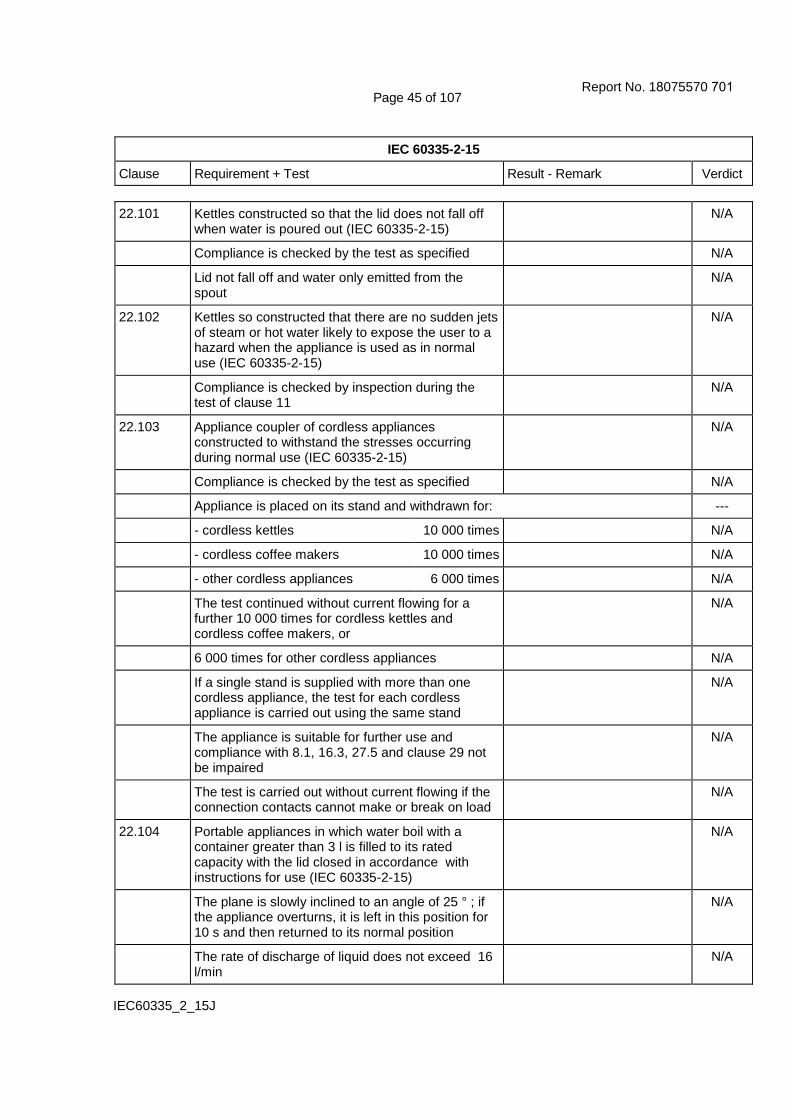
Page 45 of 107
IEC 60335-2-15
Clause Requirement + Test Result - Remark Verdict
IEC60335_2_15J
22.101 Kettles constructed so that the lid does not fall off when water is poured out (IEC 60335-2-15)
N/A
Compliance is checked by the test as specified N/A
Lid not fall off and water only emitted from the spout
N/A
22.102 Kettles so constructed that there are no sudden jets of steam or hot water likely to expose the user to a hazard when the appliance is used as in normal use (IEC 60335-2-15)
N/A
Compliance is checked by inspection during the test of clause 11
N/A
22.103 Appliance coupler of cordless appliances constructed to withstand the stresses occurring during normal use (IEC 60335-2-15)
N/A
Compliance is checked by the test as specified N/A
Appliance is placed on its stand and withdrawn for: ---
- cordless kettles 10 000 times N/A
- cordless coffee makers 10 000 times N/A
- other cordless appliances 6 000 times N/A
The test continued without current flowing for a further 10 000 times for cordless kettles and cordless coffee makers, or
N/A
6 000 times for other cordless appliances N/A
If a single stand is supplied with more than one cordless appliance, the test for each cordless appliance is carried out using the same stand
N/A
The appliance is suitable for further use and compliance with 8.1, 16.3, 27.5 and clause 29 not be impaired
N/A
The test is carried out without current flowing if the connection contacts cannot make or break on load
N/A
22.104 Portable appliances in which water boil with a container greater than 3 l is filled to its rated capacity with the lid closed in accordance with instructions for use (IEC 60335-2-15)
N/A
The plane is slowly inclined to an angle of 25 ° ; if the appliance overturns, it is left in this position for 10 s and then returned to its normal position
N/A
The rate of discharge of liquid does not exceed 16 l/min
N/A
Report No. 18075570 701

Page 46 of 107
IEC 60335-2-15
Clause Requirement + Test Result - Remark Verdict
IEC60335_2_15J
22.105 Fixed appliances for boiling water constructed so that the container is always open to the atmosphere through an aperture of at least 5 mm in diameter or 20 mm² in area with a width of at least 3 mm (IEC 60335-2-15)
N/A
Aperture not likely to be obstructed in normal use N/A
If the appliance has provisions for discharging steam or water overflowing, the discharge aperture shall be at the base of the appliance and discharge vertically downwards
N/A
22.106 Espresso coffee-maker: not possible to remove the filter by a simple operation while there is hazardous pressure within the container (IEC 60335-2-15)
N/A
22.107 Pressure cookers incorporate a non-self-resetting pressure or temperature responsive pressure relief device (IEC 60335-2-15)
N/A
22.108 Pressure cooker: not possible to remove the lid when the inner pressure is excessive (IEC 60335-2-15)
N/A
Pressure test at 4 kPa and 100 N N/A
No hazardous displacement of lid at removal N/A
Test not carried out on pressure cookers when the lid is secured by screw clamps or other devices that ensure that the pressure is automatically reduced in a controlled manner before the lid can be removed
N/A
22.109 Pressure cookers constructed so that the pressure in the container is not excessive when the lid is not closed or is incorrectly fitted (IEC 60335-2-15)
N/A
Compliance is checked by the test as specified N/A
Pressure not exceeding 4,0 kPa N/A
22.110 Feeding-bottle heater: visible or audible signal to indicate the end of the heating period (IEC 60335-2-15)
N/A
22.111 Espresso coffee-makers, incorporating a pressurized reservoir filled by the user constructed so that there is no spillage of water or sudden jets of steam or hot water (IEC 60335-2-15)
N/A
When removing the filling cap of the pressurized reservoir, before the cap is removed completely, the pressure relieves in a controlled manner
N/A
Report No. 18075570 701

Page 47 of 107
IEC 60335-2-15
Clause Requirement + Test Result - Remark Verdict
IEC60335_2_15J
Compliance is checked by inspection during the test of clause 11 and by removing the filling cap at the end of the test
N/A
22.112 Soy milk makers constructed so that steam or hot water are not ejected which may expose the user to a hazard (IEC 60335-2-15)
N/A
22.113 Appliances with moving mechanical parts constructed so that lubricants are prevented from polluting food compartments (IEC 60335-2-15)
N/A
22.114 Appliances constructed so that food or liquids are prevented from penetrating into places that could cause electrical or mechanical faults (IEC 60335-2-15)
P
23 INTERNAL WIRING ---
23.1 Wireways smooth and free from sharp edges P
Wires protected against contact with burrs, cooling fins etc.
P
Wire holes in metal well-rounded or provided with bushings
N/A
Wiring effectively prevented from coming into contact with moving parts
P
23.2 Beads etc. on live wires cannot change their position, and are not resting on sharp edges
N/A
Beads inside flexible metal conduits contained within an insulating sleeve
N/A
23.3 Electrical connections and internal conductors movable relatively to each other not exposed to undue stress
N/A
Flexible metallic tubes not causing damage to insulation of conductors
N/A
Open-coil springs not used N/A
Adequate insulating lining provided inside a coiled spring, the turns of which touch one another
N/A
No damage after 10 000 flexings for conductors flexed during normal use, or
P
100 flexings for conductors flexed during user maintenance
N/A
Electric strength test of 16.3, 1000 V between live parts and accessible metal parts
P
Report No. 18075570 701

Page 48 of 107
IEC 60335-2-15
Clause Requirement + Test Result - Remark Verdict
IEC60335_2_15J
Not more than 10% of the strands of any conductor broken, and
P
not more than 30% for wiring supplying circuits that consume no more than 15W
N/A
23.4 Bare internal wiring sufficiently rigid and fixed N/A
23.5 The insulation of internal wiring subjected to the supply mains voltage withstanding the electrical stress likely to occur in normal use
P
Basic insulation electrically equivalent to the basic insulation of cords complying with IEC 60227 or IEC 60245, or
P
no breakdown when a voltage of 2000 V is applied for 15 min between the conductor and metal foil wrapped around the insulation
P
23.6 Sleeving used as supplementary insulation on internal wiring retained in position by clamping at both ends, or
N/A
be such that it can only be removed by breaking or cutting
P
23.7 The colour combination green/yellow only used for earthing conductors
P
23.8 Aluminium wires not used for internal wiring P
23.9 Stranded conductors not consolidated by soldering where they are subjected to contact pressure, unless
N/A
the contact pressure is provided by spring terminals N/A
23.10 The insulation and sheath of internal wiring, incorporated in external hoses for the connection of an appliance to the water mains, at least equivalent to that of light polyvinyl chloride sheathed flexible cord (60227 IEC 52)
N/A
24 COMPONENTS ---
24.1 Components comply with safety requirements in relevant IEC standards
P
List of components ................................................: (see appended table) P
If components have not been tested and found to comply with relevant IEC standard for the number of cycles specified, they are tested in accordance with 24.1.1 to 24.1.9
P
Report No. 18075570 701

Page 49 of 107
IEC 60335-2-15
Clause Requirement + Test Result - Remark Verdict
IEC60335_2_15J
For components mentioned in 24.1.1 to 24.1.9 no additional tests specified in the relevant component standard are necessary other than those specified in 24.1.1 to 24.1.9
P
Components not tested and found to comply with relevant IEC standard and components not marked or not used in accordance with its marking, tested under the conditions occurring in the appliance
P
Lampholders and starterholders that have not being tested and found to comply with the relevant IEC standard, tested as a part of the appliance and additionally according to the gauging and interchangeability requirements of the relevant IEC standard
N/A
No additional tests specified for nationally standardized plugs such as those detailed in IEC/TR 60083 or connectors complying with the standard sheets of IEC 60320-1 and IEC 60309
P
24.1.1 Capacitors likely to be permanently subjected to the supply voltage and used for radio interference suppression or for voltage dividing, complying with IEC 60384-14
N/A
If the capacitors have to be tested, they are tested according to Annex F
N/A
24.1.2 Safety isolating transformers complying with IEC 61558-2-6
N/A
If they have to be tested, they are tested according to Annex G
N/A
24.1.3 Switches complying with IEC 61058-1, the number of cycles of operation being at least 10 000
P
If they have to be tested, they are tested according to Annex H
P
If the switch operates a relay or contactor, the complete switching system is subjected to the test
N/A
If the switch only operates a motor staring relay complying with IEC 60730-2-10 with the number of cycles of a least 10 000 as specified, the complete switching system need not be tested
N/A
Switches incorporated in espresso coffee-makers for initiating brewing or steaming tested for 10 000 cycles (IEC 60335-2-15)
N/A
Report No. 18075570 701
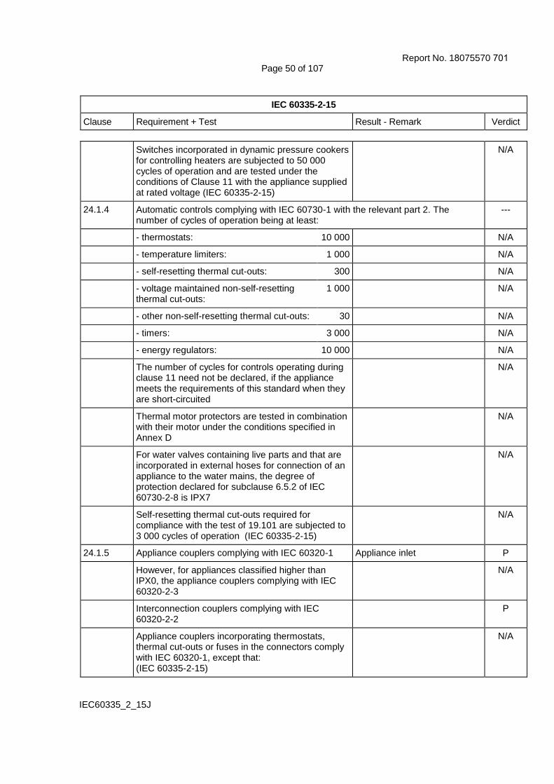
Page 50 of 107
IEC 60335-2-15
Clause Requirement + Test Result - Remark Verdict
IEC60335_2_15J
Switches incorporated in dynamic pressure cookers for controlling heaters are subjected to 50 000 cycles of operation and are tested under the conditions of Clause 11 with the appliance supplied at rated voltage (IEC 60335-2-15)
N/A
24.1.4 Automatic controls complying with IEC 60730-1 with the relevant part 2. The number of cycles of operation being at least:
---
- thermostats: 10 000 N/A
- temperature limiters: 1 000 N/A
- self-resetting thermal cut-outs: 300 N/A
- voltage maintained non-self-resetting thermal cut-outs:
1 000 N/A
- other non-self-resetting thermal cut-outs: 30 N/A
- timers: 3 000 N/A
- energy regulators: 10 000 N/A
The number of cycles for controls operating during clause 11 need not be declared, if the appliance meets the requirements of this standard when they are short-circuited
N/A
Thermal motor protectors are tested in combination with their motor under the conditions specified in Annex D
N/A
For water valves containing live parts and that are incorporated in external hoses for connection of an appliance to the water mains, the degree of protection declared for subclause 6.5.2 of IEC 60730-2-8 is IPX7
N/A
Self-resetting thermal cut-outs required for compliance with the test of 19.101 are subjected to 3 000 cycles of operation (IEC 60335-2-15)
N/A
24.1.5 Appliance couplers complying with IEC 60320-1 Appliance inlet P
However, for appliances classified higher than IPX0, the appliance couplers complying with IEC 60320-2-3
N/A
Interconnection couplers complying with IEC 60320-2-2
P
Appliance couplers incorporating thermostats, thermal cut-outs or fuses in the connectors comply with IEC 60320-1, except that: (IEC 60335-2-15)
N/A
Report No. 18075570 701

Page 51 of 107
IEC 60335-2-15
Clause Requirement + Test Result - Remark Verdict
IEC60335_2_15J
- the earthing contact of connector is allowed to be accessible, if contact is not likely to be gripped during insertion or withdrawal of the connector
N/A
- the temperature required for the test of clause 18 is that measured on the pins of the appliance inlet during test of clause 11 of this standard
N/A
- the breaking-capacity test of clause 19 carried out using the inlet of the appliance
N/A
- the temperature rise of current-carrying parts specified in clause 21 not determined
N/A
Thermal controls are not allowed in connectors complying with the standard sheets of IEC 60320-1 (IEC 60335-2-15)
P
24.1.6 Small lamp holders similar to E10 lampholders complying with IEC 60238, the requirements for E10 lampholders being applicable
N/A
24.1.7 For remote operation of the appliance via a telecommunication network, the relevant standard for the telecommunication interface circuitry in the appliance is IEC 62151
N/A
24.1.8 The relevant standard for thermal links is IEC 60691
P
Thermal links not complying with IEC 60691 are considered to be an intentionally weak part for the purposes of Clause 19
N/A
24.1.9 Contactors and relays, other than motor starting relays, tested as part of the appliance
N/A
They are also tested in accordance with Clause 17 of IEC 60730-1, the number of cycles of operations in 24.1.4 selected according to the contactor or relay function in the appliance ...............................:
N/A
24.2 Appliances not fitted with: ---
- switches or automatic controls in flexible cords P
- devices causing the protective device in the fixed wiring to operate in the event of a fault in the appliance
P
- thermal cut-outs that can be reset by soldering, unless
N/A
the solder has a melding point of at least 230 ˚C N/A
Report No. 18075570 701

Page 52 of 107
IEC 60335-2-15
Clause Requirement + Test Result - Remark Verdict
IEC60335_2_15J
24.3 Switches intended for all-pole disconnection of stationary appliances are directly connected to the supply terminals and have a contact separation in all poles, providing full disconnection under overvoltage category III conditions
N/A
24.4 Plugs and socket-outlets for extra-low voltage circuits and heating elements, not interchangeable with plugs and socket-outlets listed in IEC/TR 60083 or IEC 60906-1 or with connectors and appliance inlets complying with the standard sheets of IEC 60320-1
P
Not applicable to the connection between the appliance and the stand of cordless appliances (IEC 60335-2-15)
N/A
24.5 Capacitors in auxiliary windings of motors marked with their rated voltage and capacitance, and used accordingly
N/A
Voltage across capacitors in series with a motor winding does not exceed 1,1 times rated voltage, when the appliance is supplied at 1,1 times rated voltage under minimum load
N/A
24.6 Working voltage of motors connected to the supply mains and having basic insulation that is inadequate for the rated voltage of the appliance, not exceeding 42 V
N/A
In addition, the motors comply with the requirements of Annex I
N/A
24.7 Detachable hose-sets for connection of appliances to the water mains comply with IEC 61770
N/A
They are supplied with the appliance N/A
Appliances intended to be permanently connected to the water mains not connected by a detachable hose-set
N/A
24.8 Motor running capacitors in appliances for which 30.2.3 is applicable and that are permanently connected in series with a motor winding, not causing a hazard in event of a failure
N/A
One or more of the following conditions are to be met: ---
- the capacitors are of class P2 according to IEC 60252-1
N/A
- the capacitors are housed within a metallic or ceramic enclosure
N/A
Report No. 18075570 701

Page 53 of 107
IEC 60335-2-15
Clause Requirement + Test Result - Remark Verdict
IEC60335_2_15J
- the distance of separation of the outer surface to adjacent non-metallic parts exceeds 50 mm
N/A
- adjacent non-metallic parts within 50 mm withstand the needle-flame test of Annex E
N/A
- adjacent non-metallic parts within 50 mm classified as at least V-1 according to IEC 60695-11-10
N/A
24.101 Devices incorporated in appliance, other than kettles, in order to comply with 19.4 are non-self-resetting (IEC 60335-2-15)
P
However, self-resetting thermal cut-outs are allowed for fixed water boilers, if they have been tested for 10 000 cycles of operation
N/A
Compliance is checked by inspection and during the test of 19.4
P
25 SUPPLY CONNECTION AND EXTERNAL FLEXIBLE CORDS ---
25.1 Appliance not intended for permanent connection to fixed wiring, means for connection to the supply:
---
- supply cord fitted with a plug, P
- an appliance inlet having at least the same degree of protection against moisture as required for the appliance, or
P
- pins for insertion into socket-outlets N/A
Appliances incorporating an appliance inlet other than those standardized in IEC 60320-1 are supplied with a cord set (IEC 60335-2-15)
N/A
25.2 Appliance not provided with more than one means of connection to the supply mains
P
Stationary appliance for multiple supply may be provided with more than one means of connection, provided electric strength test of 1250 V for 1 min between each means of connection causes no breakdown
N/A
25.3 Appliance intended to be permanently connected to fixed wiring provided with one of the following means for connection to the supply mains:
---
- a set of terminals allowing the connection of a flexible cord
N/A
- a fitted supply cord N/A
- a set of supply leads accommodated in a suitable compartment
N/A
Report No. 18075570 701

Page 54 of 107
IEC 60335-2-15
Clause Requirement + Test Result - Remark Verdict
IEC60335_2_15J
- a set of terminals for the connection of cables of fixed wiring, cross-sectional areas specified in 26.6, and the appliance allows the connection of the supply conductors after the appliance has been fixed to its support
N/A
- a set of terminals and cable entries, conduit entries, knock-outs or glands, allowing connection of appropriate types of cable or conduit, and the appliance allows the connection of the supply conductors after the appliance has been fixed to its support
N/A
For a fixed appliance constructed so that parts can be removed to facilitate easy installation, this requirement is met if it is possible to connect the fixed wiring without difficulty after a part of the appliance has been fixed to its support
N/A
25.4 Cable and conduit entries, rated current of appliance not exceeding 16 A, dimension according to table 10 (mm) ....................................................:
N/A
Introduction of conduit or cable does not reduce clearances or creepage distances below values specified in clause 29
N/A
25.5 Method for assembling the supply cord to the appliance: ---
- type X attachment N/A
- type Y attachment P
- type Z attachment, if allowed in relevant part 2 N/A
Type Z attachment is allowed for egg boilers, feeding bottle heaters, yoghurt makers and stands of cordless appliances (IEC 60335-2-15)
N/A
Type X attachment, other than those with a specially prepared cord, not used for flat twin tinsel cords
N/A
For multi-phase appliances supplied with a supply cord and that are intended to be permanently connected to fixed wiring, the supply cord is assembled to the appliance by type Y attachment
N/A
25.6 Plugs fitted with only one flexible cord P
25.7 Supply cords, other than for class III appliances, being one of the following types: ---
- rubber sheathed (at least 60245 IEC 53) N/A
- polychloroprene sheathed (at least 60245 IEC 57) N/A
Report No. 18075570 701

Page 55 of 107
IEC 60335-2-15
Clause Requirement + Test Result - Remark Verdict
IEC60335_2_15J
- cross-linked polyvinyl chloride sheathed (at least 60245 IEC 88)
N/A
- polyvinyl chloride sheathed. Not used if they are likely to touch metal parts having a temperature rise exceeding 75 K during the test of clause 11
---
light polyvinyl chloride sheathed cord(60227 IEC 52), for appliances notexceeding 3 kg
N/A
ordinary polyvinyl chloride sheathed cord(60227 IEC 53), for other appliances
H05VV-F P
- heat resistant polyvinyl chloride sheathed. Not used for type X attachment other than specially prepared cords
---
heat-resistant light polyvinyl chloridesheathed cord (60227 IEC 56), forappliances not exceeding 3 kg
N/A
heat-resistant polyvinyl chloride sheathedcord (60227 IEC 57), for other appliances
N/A
Supply cords for class III appliances adequately insulated
N/A
Test with 500 V for 2 min for supply cords of class III appliances that contain live parts
N/A
Supply cord of livestock feed boilers are polychloroprene sheathed (IEC 60335-2-15)
N/A
25.8 Nominal cross-sectional area of supply cords not less than table 11; rated current (A); cross-sectional area (mm²) .............................................................:
Rated current: 9.09A;
Cross-sectional area:0.75mm²
P
Portable appliances having a rated current of up to 10 A may incorporate a supply cord having a nominal cross-sectional area of 0,75 mm², if the length is less than 2 m (IEC 60335-2-15)
P
25.9 Supply cords not in contact with sharp points or edges
P
25.10 Supply cord of class I appliances have a green/yellow core for earthing
P
25.11 Conductors of supply cords not consolidated by soldering where they are subject to contact pressure, unless
P
the contact pressure is provided by spring terminals N/A
25.12 Insulation of the supply cord not damaged when moulding the cord to part of the enclosure
P
Report No. 18075570 701

Page 56 of 107
IEC 60335-2-15
Clause Requirement + Test Result - Remark Verdict
IEC60335_2_15J
25.13 Inlet openings so constructed as to prevent damage to the supply cord
P
If the enclosure at the inlet opening is not of insulating material, a non-detachable lining or bushing complying with 29.3 for supplementary insulation provided
N/A
If unsheathed supply cord, a similar additional bushing or lining is required, unless the appliance is
N/A
class 0, or N/A
a class III appliance not containing live parts N/A
25.14 Supply cords moved while in operation adequately protected against excessive flexing
N/A
Flexing test, as described: ---
- applied force (N) ..................................................: N/A
- number of flexings ...............................................: N/A
The test does not result in: ---
- short-circuit between the conductors, such that the current exceeds a value of twice the rated current
N/A
- breakage of more than 10% of the strands of any conductor
N/A
- separation of the conductor from its terminal N/A
- loosening of any cord guard N/A
- damage to the cord or the cord guard N/A
- broken strands piercing the insulation and becoming accessible
N/A
25.15 For appliances with supply cord and appliances to be permanently connected to fixed wiring by a flexible cord, conductors of the supply cord relieved from strain, twisting and abrasion by use of cord anchorage
P
The cord cannot be pushed into the appliance to such an extent that the cord or internal parts of the appliance can be damaged
P
Pull and torque test of supply cord, values shown in table 12: mass (kg); pull (N); torque (not on automatic cord reel) (Nm)......................................:
3.1Kg, 60N, 0.25Nm P
Cord not damaged and max. 2 mm displacement of the cord
P
Report No. 18075570 701

Page 57 of 107
IEC 60335-2-15
Clause Requirement + Test Result - Remark Verdict
IEC60335_2_15J
25.16 Cord anchorages for type X attachments constructed and located so that: ---
- replacement of the cord is easily possible N/A
- it is clear how the relief from strain and the prevention of twisting are obtained
N/A
- they are suitable for different types of supply cord N/A
- cord cannot touch the clamping screws of cord anchorage if these screws are accessible, unless
N/A
they are separated from accessible metal parts by supplementary insulation
N/A
- the cord is not clamped by a metal screw which bears directly on the cord
N/A
- at least one part of the cord anchorage securely fixed to the appliance, unless
N/A
it is part of a specially prepared cord N/A
- screws which have to be operated when replacing the cord do not fix any other component, unless
N/A
the appliance becomes inoperative or incomplete or the parts cannot be removed without a tool
N/A
- if labyrinths can be bypassed the test of 25.15 is nevertheless withstood
N/A
- for class 0, 0I and I appliances they are of insulating material or are provided with an insulating lining, unless
N/A
failure of the insulation of the cord does not make accessible metal parts live
N/A
- for class II appliances they are of insulating material, or
N/A
if of metal, they are insulated from accessible metal parts by supplementary insulation
N/A
After the test of 25.15, under the conditions specified, the conductors have not moved by more than 1 mm in the terminals
N/A
25.17 Adequate cord anchorages for type Y and Z attachment, test with the cord supplied with the appliance
P
25.18 Cord anchorages only accessible with the aid of a tool, or
P
Constructed so that the cord can only be fitted with the aid of a tool
P
Report No. 18075570 701

Page 58 of 107
IEC 60335-2-15
Clause Requirement + Test Result - Remark Verdict
IEC60335_2_15J
25.19 Type X attachment, glands not used as cord anchorage in portable appliances
N/A
Tying the cord into a knot or tying the cord with string not used
N/A
25.20 The insulated conductors of the supply cord for type Y and Z attachment additionally insulated from accessible metal parts
P
25.21 Space for supply cord for type X attachment or for connection of fixed wiring constructed:
---
- to permit checking of conductors with respect to correct positioning and connection before fitting any cover
N/A
- so there is no risk of damage to the conductors or their insulation when fitting the cover
N/A
- for portable appliances, so that the uninsulated end of a conductor, if it becomes free from the terminal, prevented from contact with accessible metal parts
N/A
2 N test to the conductor for portable appliances; no contact with accessible metal parts
N/A
25.22 Appliance inlets: ---
- live parts not accessible during insertion or removal
P
Requirement not applicable to appliance inlets complying with IEC 60320-1
P
- connector can be inserted without difficulty P
- the appliance is not supported by the connector P
- not for cold conditions if temp. rise of external metal parts exceeds 75 K during clause 11, unless
P
the supply cord is unlikely to touch such metal parts N/A
Soy milk maker inlets located so that pollution by soy milk is unlikely to occur during normal use (IEC 60335-2-15)
N/A
25.23 Interconnection cords comply with the requirements for the supply cord, except that:
N/A
- the cross-sectional area of the conductors is determined on the basis of the maximum current during clause 11
N/A
- the thickness of the insulation may be reduced N/A
Report No. 18075570 701

Page 59 of 107
IEC 60335-2-15
Clause Requirement + Test Result - Remark Verdict
IEC60335_2_15J
If necessary, electric strength test of 16.3 N/A
25.24 Interconnection cords not detachable without the aid of a tool if compliance with this standard is impaired when they are disconnected
N/A
25.25 Dimensions of pins that are inserted into socket-outlets compatible with the dimensions of the relevant socket-outlet.
N/A
Dimensions of pins and engagement face in accordance with the dimensions of the relevant plug in IEC/TR 60083
N/A
25.101 Supply cords of kettles are not longer than 75 cm, unless they are helically coiled (IEC 60335-2-15)
N/A
If a cordless kettle has a cord storage facility, the length of the cord is measured after storing as much of the cord as possible
N/A
The length of the cord is measured between the plug and the point where the cord or cord guard enters the appliance
N/A
26 TERMINALS FOR EXTERNAL CONDUCTORS ---
26.1 Appliances provided with terminals or equally effective devices for connection of external conductors
P
Terminals only accessible after removal of a non-detachable cover, except
P
for class III appliances that do not contain live parts N/A
Earthing terminals may be accessible if a tool is required to make the connections and means are provided to clamp the wire independently from its connection
N/A
26.2 Appliances with type X attachment and appliances for the connection of cables to fixed wiring provided with terminals in which connections are made by means of screws, nuts or similar devices, unless
N/A
the connections are soldered N/A
Screws and nuts not used to fix any other component, except
N/A
internal conductors, if so arranged that they are unlikely to be displaced when fitting the supply conductors
N/A
Report No. 18075570 701
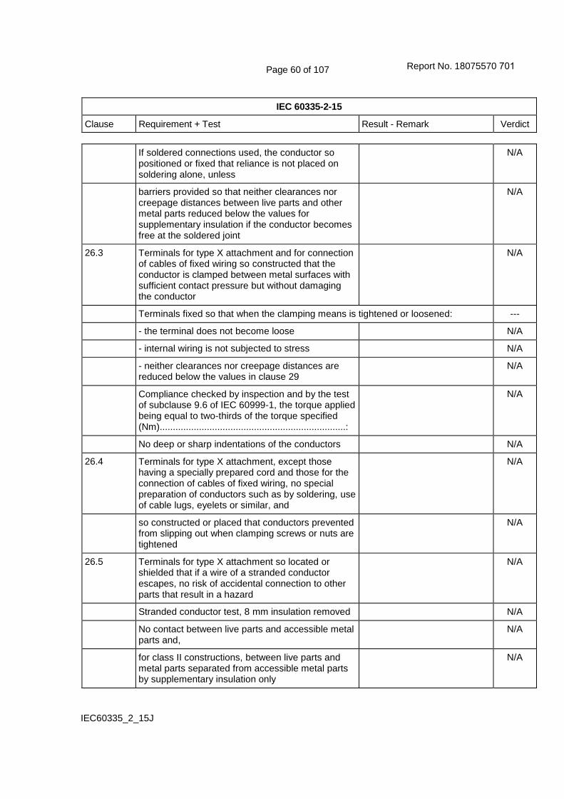
Page 60 of 107
IEC 60335-2-15
Clause Requirement + Test Result - Remark Verdict
IEC60335_2_15J
If soldered connections used, the conductor so positioned or fixed that reliance is not placed on soldering alone, unless
N/A
barriers provided so that neither clearances nor creepage distances between live parts and other metal parts reduced below the values for supplementary insulation if the conductor becomes free at the soldered joint
N/A
26.3 Terminals for type X attachment and for connection of cables of fixed wiring so constructed that the conductor is clamped between metal surfaces with sufficient contact pressure but without damaging the conductor
N/A
Terminals fixed so that when the clamping means is tightened or loosened: ---
- the terminal does not become loose N/A
- internal wiring is not subjected to stress N/A
- neither clearances nor creepage distances are reduced below the values in clause 29
N/A
Compliance checked by inspection and by the test of subclause 9.6 of IEC 60999-1, the torque applied being equal to two-thirds of the torque specified (Nm) .......................................................................:
N/A
No deep or sharp indentations of the conductors N/A
26.4 Terminals for type X attachment, except those having a specially prepared cord and those for the connection of cables of fixed wiring, no special preparation of conductors such as by soldering, use of cable lugs, eyelets or similar, and
N/A
so constructed or placed that conductors prevented from slipping out when clamping screws or nuts are tightened
N/A
26.5 Terminals for type X attachment so located or shielded that if a wire of a stranded conductor escapes, no risk of accidental connection to other parts that result in a hazard
N/A
Stranded conductor test, 8 mm insulation removed N/A
No contact between live parts and accessible metal parts and,
N/A
for class II constructions, between live parts and metal parts separated from accessible metal parts by supplementary insulation only
N/A
Report No. 18075570 701

Page 61 of 107
IEC 60335-2-15
Clause Requirement + Test Result - Remark Verdict
IEC60335_2_15J
26.6 Terminals for type X attachment and for connection of cables of fixed wiring suitable for connection of conductors with cross-sectional area according to table 13; rated current (A); nominal cross-sectional area (mm²) .............................................................:
N/A
If a specially prepared cord is used, terminals need only be suitable for that cord
N/A
26.7 Terminals for type X attachment, except in class III appliances not containing live parts, accessible after removal of a cover or part of the enclosure
N/A
26.8 Terminals for the connection of fixed wiring, including the earthing terminal, located close to each other
N/A
26.9 Terminals of the pillar type constructed and located as specified
N/A
26.10 Terminals with screw clamping and screwless terminals not used for flat twin tinsel cords, unless
P
conductors ends fitted with means suitable for screw terminals
N/A
Pull test of 5 N to the connection P
26.11 For type Y and Z attachment, soldered, welded, crimped or similar connections may be used
P
For Class II appliances, the conductor so positioned or fixed that reliance is not placed on soldering, welding or crimping alone
N/A
If soldering, welding or crimping alone used, barriers provided so that clearances and creepage distances between live parts and other metal parts are not reduced below the values for supplementary insulation if the conductor becomes free
N/A
27 PROVISION FOR EARTHING ---
27.1 Accessible metal parts of Class 0I and I appliances permanently and reliably connected to an earthing terminal or earthing contact of the appliance inlet
P
Earthing terminals and earthing contacts not connected to the neutral terminal
P
Class 0, II and III appliances have no provision for earthing
N/A
Safety extra-low voltage circuits not earthed, unless N/A
protective extra-low voltage circuits N/A
Report No. 18075570 701

Page 62 of 107
IEC 60335-2-15
Clause Requirement + Test Result - Remark Verdict
IEC60335_2_15J
27.2 Clamping means of earthing terminals adequately secured against accidental loosening
P
Terminals for the connection of external equipotential bonding conductors allow connection of conductors of 2.5 to 6 mm², and
N/A
do not provide earthing continuity between different parts of the appliance, and
N/A
conductors cannot be loosened without the aid of a tool
N/A
27.3 For a detachable part having an earth connection and being plugged into another part of the appliance, the earth connection is made before and separated after current-carrying connections when removing the part
P
For appliances with supply cords, current-carrying conductors become taut before earthing conductor, if the cord slips out of the cord anchorage
P
27.4 No risk of corrosion resulting from contact between parts of the earthing terminal and the copper of the earthing conductor or other metal
P
Parts providing earthing continuity, other than parts of a metal frame or enclosure, have adequate resistance to corrosion
P
If of steel, these parts provided with an electroplated coating with a thickness at least 5 µm
P
Adequate protection against rusting of parts of coated or uncoated steel, only intended to provide or transmit contact pressure
P
In the body of the earthing terminal is a part of a frame or enclosure of aluminium or aluminium alloys, precautions taken to avoid risk of corrosion
P
27.5 Low resistance of connection between earthing terminal and earthed metal parts
P
This requirement does not apply to connections providing earthing continuity in the protective extra-low voltage circuit, provided the clearances of basic insulation are based on the rated voltage of the appliance
N/A
Resistance not exceeding 0,1 Ω at the specified low-resistance test (Ω ) .........................................:
Max. 0.003Ω P
Report No. 18075570 701

Page 63 of 107
IEC 60335-2-15
Clause Requirement + Test Result - Remark Verdict
IEC60335_2_15J
27.6 The printed conductors of printed circuit boards not used to provide earthing continuity in hand-held appliances.
N/A
They may be used to provide earthing continuity in other appliances if at least two tracks are used with independent soldering points and the appliance complies with 27.5 for each circuit
N/A
28 SCREWS AND CONNECTIONS ---
28.1 Fixings, electrical connections and connections providing earthing continuity withstand mechanical stresses
P
Screws not of soft metal liable to creep, such as zinc or aluminium
P
Diameter of screws of insulating material min. 3 mm
N/A
Screws of insulating material not used for any electrical connections or connections providing earthing continuity
N/A
Screws used for electrical connections or connections providing earthing continuity screwed into metal
P
Screws not of insulating material if their replacement by a metal screw can impair supplementary or reinforced insulation
P
For type X attachment, screws to be removed for replacement of supply cord or for user maintenance, not of insulating material if their replacement by a metal screw impairs basic insulation
N/A
For screws and nuts; torque-test as specified in table 14 ..................................................................:
(see appended table) P
28.2 Electrical connections and connections providing earthing continuity constructed so that contact pressure is not transmitted through non-ceramic insulating material liable to shrink or distort, unless
P
there is resiliency in the metallic parts to compensate for shrinkage or distortion of the insulating material
P
This requirement does not apply to electrical connections in circuits of appliances for which:
---
30.2.2 is applicable and that carry a currentnot exceeding 0,5 A
N/A
Report No. 18075570 701

Page 64 of 107
IEC 60335-2-15
Clause Requirement + Test Result - Remark Verdict
IEC60335_2_15J
30.2.3 is applicable and that carry a currentnot exceeding 0,2 A
N/A
28.3 Space-threaded (sheet metal) screws only used for electrical connections if they clamp the parts together
P
Thread-cutting (self-tapping) screws and thread rolling screws only used for electrical connections if they generate a full form standard machine screw thread
N/A
Thread-cutting (self-tapping) screws not used if they are likely to be operated by the user or installer
P
Thread-cutting, thread rolling and space threaded screws may be used in connections providing earthing continuity provided it is not necessary to disturb the connection:
---
- in normal use, N/A
- during user maintenance, N/A
- when replacing a supply cord having a type X attachment, or
N/A
- during installation N/A
At least two screws being used for each connection providing earthing continuity, unless
P
the screw forms a thread having a length of at least half the diameter of the screw
N/A
28.4 Screws and nuts that make mechanical connection secured against loosening if they also make electrical connections or connections providing earthing continuity
P
This requirement does not apply to screws in the earthing circuit if at least two screws are used, or
N/A
if an alternative earthing circuit is provided N/A
Rivets for electrical connections or connections providing earthing continuity secured against loosening if the connections are subjected to torsion
N/A
29 CLEARANCES, CREEPAGE DISTANCES AND SOLID INSULATION ---
Clearances, creepage distances and solid insulation withstand electrical stress
P
Report No. 18075570 701

Page 65 of 107
IEC 60335-2-15
Clause Requirement + Test Result - Remark Verdict
IEC60335_2_15J
For coatings used on printed circuits boards to protect the microenvironment (Type 1) or to provide basic insulation (Type 2), Annex J applies ............:
N/A
The microenvironment is pollution degree 1 under type 1 protection
N/A
For type 2 protection, the spacing between the conductors before the protection is applied is not less than the values specified in Table 1 of IEC 60664-3
N/A
These values apply to functional, basic, supplementary and reinforced insulation ..............:
P
29.1 Clearances not less than the values specified in table 16, taking into account the rated impulse voltage for the overvoltage categories of table 15, unless ....................................................................:
(see appended table) P
for basic insulation and functional insulation they comply with the impulse voltage test of clause 14
P
However, if the distances are affected by wear, distortion, movement of the parts or during assembly, the clearances for rated impulse voltages of 1500V and above are increased by 0,5 mm and the impulse voltage test is not applicable
N/A
Impulse voltage test is not applicable: ---
- when the microenvironment is pollution degree 3, or
P
- for basic insulation of class 0 and class 01 appliances
N/A
Appliances are in overvoltage category II P
A force of 2 N is applied to bare conductors, other than heating elements
P
A force of 30 N is applied to accessible surfaces P
29.1.1 Clearances of basic insulation withstand the overvoltages, taking into account the rated impulse voltage
P
The values of table 16 or the impulse voltage test of clause 14 are applicable........................................:
(see appended table) P
Clearance at the terminals of tubular sheathed heating elements may be reduced to 1,0 mm if the microenvironment is pollution degree 1
N/A
Lacquered conductors of windings considered to be bare conductors
N/A
Report No. 18075570 701

Page 66 of 107
IEC 60335-2-15
Clause Requirement + Test Result - Remark Verdict
IEC60335_2_15J
29.1.2 Clearances of supplementary insulation not less than those specified for basic insulation in table 16:
(see appended table) P
29.1.3 Clearances of reinforced insulation not less than those specified for basic insulation in table 16, using the next higher step for rated impulse voltage ...............................................................................:
(see appended table) P
For double insulation, with no intermediate conductive part between basic and supplementary insulation, clearances are measured between live parts and the accessible surface, and the insulation system is treated as reinforced insulation
P
29.1.4 Clearances for functional insulation are the largest values determined from: ---
- table 16 based on the rated impulse voltage ......: (see appended table) P
- table F.7a in IEC 60664-1, frequency not exceeding 30 kHz
N/A
- clause 4 of IEC 60664-4, frequency exceeding 30 kHz
N/A
If values of table 16 are largest, the impulse voltage test of clause 14 may be applied instead, unless
N/A
the microenvironment is pollution degree 3, or N/A
the distances can be affected by wear, distortion, movement of the parts or during assembly
N/A
However, clearances are not specified if the appliance complies with clause 19 with the functional insulation short-circuited
N/A
Lacquered conductors of windings considered to be bare conductors
N/A
However, clearances at crossover points are not measured
N/A
Clearance between surfaces of PTC heating elements may be reduced to 1mm
N/A
29.1.5 Appliances having higher working voltages than rated voltage, clearances for basic insulation are the largest values determined from:
---
- table 16 based on the rated impulse voltage ......: N/A
- table F.7a in IEC 60664-1, frequency not exceeding 30 kHz
N/A
- clause 4 of IEC 60664-4, frequency exceeding 30 kHz
N/A
Report No. 18075570 701

Page 67 of 107
IEC 60335-2-15
Clause Requirement + Test Result - Remark Verdict
IEC60335_2_15J
If clearances for basic insulation are selected from Table F.7a of IEC 60664-1 or Clause 4 of IEC 60664-4, the clearances of supplementary insulation are not less than those specified for basic insulation
N/A
If clearances for basic insulation are selected from Table F.7a of IEC 60664-1, the clearances of reinforced insulation dimensioned as specified in Table F.7a are to withstand 160% of the withstand voltage required for basic insulation
N/A
If clearances for basic insulation are selected from Clause 4 of IEC 60664-4, the clearances of reinforced insulation are twice the value required for basic insulation
N/A
If the secondary winding of a step-down transformer is earthed, or if there is an earthed screen between the primary and secondary windings, clearances of basic insulation on the secondary side not less than those specified in table 16, but using the next lower step for rated impulse voltage
N/A
Circuits supplied with a voltage lower than rated voltage, clearances of functional insulation are based on the working voltage used as the rated voltage in table 15
N/A
29.2 Creepage distances not less than those appropriate for the working voltage, taking into account the material group and the pollution degree ................:
(see appended table) P
Pollution degree 2 applies, unless N/A
- precautions taken to protect the insulation; pollution degree 1
N/A
- insulation subjected to conductive pollution; pollution degree 3
P
The microenvironment is pollution degree 3 if the insulation can be polluted by condensation from steam produced during normal use of the appliance (IEC 60335-2-15)
N/A
A force of 2 N is applied to bare conductors, other than heating elements
P
A force of 30 N is applied to accessible surfaces P
Report No. 18075570 701

Page 68 of 107
IEC 60335-2-15
Clause Requirement + Test Result - Remark Verdict
IEC60335_2_15J
In a double insulation system, the working voltage for both the basic and supplementary insulation is taken as the working voltage across the complete double insulation system
N/A
29.2.1 Creepage distances of basic insulation not less than specified in table 17.......................................:
(see appended table) P
However, if the working voltage is periodic and has a frequency exceeding 30 kHz, the creepage distances are also determined from table 2 of IEC 60664-4, these values being used if exceeding the values in table 17 ..................................................:
N/A
Except for pollution degree 1, corresponding creepage distance not less than the minimum specified for the clearance in table 16, if the clearance has been checked according to the test of clause 14 ...........................................................:
N/A
29.2.2 Creepage distances of supplementary insulation at least those specified for basic insulation in table 17, or ...........................................................................:
(see appended table) P
Table 2 of IEC 60664-4, as applicable ..................: N/A
29.2.3 Creepage distances of reinforced insulation at least double those specified for basic insulation in table 17, or .....................................................................:
(see appended table) P
Table 2 of IEC 60664-4, as applicable ..................: N/A
29.2.4 Creepage distances of functional insulation not less than specified in table 18.......................................:
(see appended table) P
However, if the working voltage is periodic and has a frequency exceeding 30 kHz, the creepage distances are also determined from table 2 of IEC 60664-4, these values being used if exceeding the values in table 18 ..................................................:
N/A
Creepage distances may be reduced if the appliance complies with clause 19 with the functional insulation short-circuited
N/A
29.3 Supplementary and reinforced insulation have adequate thickness, or a sufficient number of layers, to withstand the electrical stresses
P
Compliance checked: ---
- by measurement, in accordance with 29.3.1, or P
- by an electric strength test in accordance with 29.3.2, or
N/A
Report No. 18075570 701

Page 69 of 107
IEC 60335-2-15
Clause Requirement + Test Result - Remark Verdict
IEC60335_2_15J
- by an assessment of the thermal quality of the material combined with an electric strength test, in accordance with 29.3.3, and
N/A
for accessible parts of reinforced insulation consisting of a single layer, by measurement in accordance with 29.3.4, or
N/A
- as specified in subclause 6.3 of IEC 60664-4 for insulation that is subjected to any periodic voltage having a frequency exceeding 30 kHz
N/A
29.3.1 Supplementary insulation have a thickness of at least 1 mm
P
Reinforced insulation have a thickness of at least 2 mm
P
29.3.2 Each layer of material withstand the electric strength test of 16.3 for supplementary insulation
N/A
Supplementary insulation consist of at least 2 layers
N/A
Reinforced insulation consist of at least 3 layers N/A
29.3.3 The insulation is subjected to the dry heat test Bb of IEC 60068-2-2, followed by
N/A
the electric strength test of 16.3 N/A
If the temperature rise during the tests of clause 19 does not exceed the value specified in table 3, the test of IEC 60068-2-2 is not carried out
N/A
29.3.4 Thickness of accessible parts of reinforced insulation consisting of a single layer not less than specified in table 19 ...............................................:
N/A
30 RESISTANCE TO HEAT AND FIRE ---
30.1 External parts of non-metallic material, P
parts supporting live parts, and P
parts of thermoplastic material providing supplementary or reinforced insulation
P
sufficiently resistant to heat P
Ball-pressure test according to IEC 60695-10-2 P
External parts tested at 40 C plus the maximum temperature rise determined during the test of
clause 11, or at 75 C, whichever is the higher;
temperature (C) ....................................................:
(see appended table) P
Report No. 18075570 701

Page 70 of 107
IEC 60335-2-15
Clause Requirement + Test Result - Remark Verdict
IEC60335_2_15J
Parts supporting live parts tested at 40C plus the maximum temperature rise determined during the
test of clause 11, or at 125 C, whichever is the
higher; temperature (C)........................................:
(see appended table) N/A
Parts of thermoplastic material providing supplementary or reinforced insulation tested at 25
C plus the maximum temperature rise determined
during clause 19, if higher; temperature (C) ........:
(see appended table) P
For coffee makers, egg boilers, kettles and steam cookers, the temperature rises occurring during the tests of 19.4, 19.5 and 19.101 are not taken into account (IEC 60335-2-15)
N/A
30.2 Parts of non-metallic material resistant to ignition and spread of fire
P
This requirement does not apply to: ---
parts having a mass not exceeding 0,5 g, provided the cumulative effect is unlikely to propagate flames that originate inside the appliance by propagating flames from one part to another, or
N/A
decorative trims, knobs and other parts unlikely to be ignited or to propagate flames that originate inside the appliance
P
Compliance checked by the test of 30.2.1, and in addition:
P
- for attended appliances, 30.2.2 applies N/A
- for unattended appliances, 30.2.3 applies P
For appliances for remote operation, 30.2.3 applies N/A
For base material of printed circuit boards, 30.2.4 applies
P
For water distillers, appliances incorporating a delayed start timer and appliances intended to maintain liquid or food at a particular temperature, 30.2.3 applies (IEC 60335-2-15)
P
For other appliances, 30.2.2 applies (IEC 60335-2-15:2002)
N/A
30.2.1 Parts of non-metallic material subjected to the
glow-wire test of IEC 60695-2-11 at 550 C
P
However, test not carried out if the material is classified as having a glow-wire flammability index
according to IEC 60695-2-12 of at least 550 C, or
N/A
Report No. 18075570 701

Page 71 of 107
IEC 60335-2-15
Clause Requirement + Test Result - Remark Verdict
IEC60335_2_15J
the material is classified at least HB40 according to IEC 60695-11-10
N/A
Parts for which the glow-wire test cannot be carried out need to meet the requirements in ISO 9772 for material classified HBF
N/A
30.2.2 Appliances operated while attended, parts of non-metallic material supporting current-carrying connections, and
N/A
parts of non-metallic material within a distance of 3mm of such connections,
N/A
subjected to the glow-wire test of IEC 60695-2-11 N/A
The test severity is: ---
- 750 C, for connections carrying a current exceeding 0,5 A during normal operation
N/A
- 650 C, for other connections N/A
Glow-wire applied to an interposed shielding material, if relevant
N/A
The glow-wire test is not carried out on parts of material classified as having a glow-wire flammability index according to IEC 60695-2-12 of at least:
---
- 750 C, for connections carrying a current exceeding 0,5 A during normal operation
N/A
- 650 C, for other connections N/A
The glow-wire test is also not carried out on small parts. These parts are to: ---
- comprise material having a glow-wire flammability
index of at least 750 C, or 650 C as appropriate, or
N/A
- comply with the needle-flame test of Annex E, or N/A
- comprise material classified as V-0 or V-1 according to IEC 60695-11-10 ..............................:
N/A
Glow-wire test not applicable to conditions as specified ................................................................:
N/A
30.2.3 Appliances operated while unattended, tested as specified in 30.2.3.1 and 30.2.3.2
P
The tests are not applicable to conditions as specified ................................................................:
P
30.2.3.1 Parts of non-metallic material supporting connections carrying a current exceeding 0,2 A during normal operation, and
P
Report No. 18075570 701

Page 72 of 107
IEC 60335-2-15
Clause Requirement + Test Result - Remark Verdict
IEC60335_2_15J
parts of non-metallic material, other than small parts, within a distance of 3 mm,
N/A
subjected to the glow-wire test of IEC 60695-2-11 with a test severity of 850 °C
P
Glow-wire applied to an interposed shielding material, if relevant
N/A
The glow-wire test is not carried out on parts of material classified as having a glow-wire flammability index according to IEC 60695-2-12 of at least 850 °C
N/A
30.2.3.2 Parts of non-metallic material supporting connections, and
P
parts of non-metallic material within a distance of 3mm,
P
subjected to glow-wire test of IEC 60695-2-11 P
The test severity is: ---
- 750 C, for connections carrying a current exceeding 0,2 A during normal operation
P
- 650 C, for other connections P
Glow-wire applied to an interposed shielding material, if relevant
N/A
However, the glow-wire test of 750 C or 650 C as appropriate, is not carried out on parts of material fulfilling both or either of the following classifications:
---
- a glow-wire ignition temperature according to IEC 60695-2-13 of at least:
N/A
775 C, for connections carrying a currentexceeding 0,2 A during normal operation
N/A
675 C, for other connections N/A
- a glow-wire flammability index according to IEC 60695-2-12 of at least:
P
- 750 C, for connections carrying a current exceeding 0,2 A during normal operation
P
- 650 C, for other connections P
The glow-wire test is also not carried out on small parts. These parts are to: ---
- comprise material having a glow-wire ignition
temperature of at least 775 C or 675 C as appropriate, or
N/A
Report No. 18075570 701

Page 73 of 107
IEC 60335-2-15
Clause Requirement + Test Result - Remark Verdict
IEC60335_2_15J
- comprise material having a glow-wire flammability
index of at least 750 C or 650 C as appropriate, or
N/A
- comply with the needle-flame test of Annex E, or N/A
- comprise material classified as V-0 or V-1 according to IEC 60695-11-10
N/A
The consequential needle-flame test of Annex E applied to non-metallic parts that encroach within the vertical cylinder placed above the centre of the connection zone and on top of the non-metallic parts supporting current-carrying connections, and parts of non-metallic material within a distance of 3 mm of such connections if these parts are those:
---
- parts that withstood the glow-wire test of IEC
60695-2-11 of 750 C or 650 C as appropriate, but produce a flame that persist longer than 2 s, or
P
- parts that comprised material having a glow-wire
flammability index of at least 750 C or 650 C as appropriate, or
N/A
- small parts, that comprised material having a
glow-wire flammability index of at least 750 C or
650 C as appropriate, or
N/A
- small parts for which the needle-flame test of Annex E was applied, or
P
- small parts for which a material classification of V-0 or V-1 was applied
N/A
However, the consequential needle-flame test is not carried out on non-metallic parts, including small parts, within the cylinder that are:
---
- parts having a glow-wire ignition temperature of at
least 775 C or 675 C as appropriate, or
N/A
- parts comprising material classified as V-0 or V-1 according to IEC 60695-11-10, or
N/A
- parts shielded by a flame barrier that meets the needle-flame test of Annex E or that comprises material classified as V-0 or V-1 according to IEC 60695-11-10
N/A
30.2.4 Base material of printed circuit boards subjected to the needle-flame test of Annex E
P
Test not applicable to conditions as specified .......: P
31 RESISTANCE TO RUSTING ---
Relevant ferrous parts adequately protected against rusting
P
Report No. 18075570 701

Page 74 of 107
IEC 60335-2-15
Clause Requirement + Test Result - Remark Verdict
IEC60335_2_15J
Tests specified in part 2 when necessary N/A
32 RADIATION, TOXICITY AND SIMILAR HAZARDS ---
Appliance does not emit harmful radiation or present a toxic or similar hazard due to their operation in normal use
P
Compliance is checked by the limits or tests specified in part 2, if relevant
N/A
A ANNEX A (INFORMATIVE) ROUTINE TESTS
---
Description of routine tests to be carried out by the manufacturer
N/A
B ANNEX B (NORMATIVE) APPLIANCES POWERED BY RECHARGEABLE BATTERIES
---
The following modifications to this standard are applicable for appliances powered by batteries that are recharged in the appliance
N/A
This annex does not apply to battery chargers N/A
3.1.9 Appliance operated under the following conditions: ---
- the appliance, supplied by its fully charged battery, operated as specified in relevant part 2
N/A
- the battery is charged, the battery being initially discharged to such an extent that the appliance cannot operate
N/A
-if possible, the appliance is supplied from the supply mains through its battery charger, the battery being initially discharged to such an extent that the appliance cannot operate. The appliance is operated as specified in relevant part 2
N/A
- if the appliance incorporates inductive coupling between two parts that are detachable from each other, the appliance is supplied from the supply mains with the detachable part removed
N/A
3.6.2 Part to be removed in order to discard the battery is not considered to be detachable
N/A
5.B.101 Appliances supplied from the supply mains tested as specified for motor-operated appliances
N/A
7.1 Battery compartment for batteries intended to be replaced by the user, marked with battery voltage and polarity of the terminals
N/A
Report No. 18075570 701

Page 75 of 107
IEC 60335-2-15
Clause Requirement + Test Result - Remark Verdict
IEC60335_2_15J
The positive terminal indicated by symbol IEC 60417-5005 and the negative terminal by symbol IEC 60417-5006
N/A
7.6 Symbols 60417-5005 and IEC 60417-5006 N/A
7.12 The instructions give information regarding charging
N/A
The instructions for appliances incorporating batteries intended to be replaced by the user includes required information
N/A
Details about how to remove batteries containing materials hazardous to the environment given
N/A
7.15 Markings placed on the part of the appliance connected to the supply mains
N/A
8.2 Appliances having batteries that according to the instruction may be replaced by the user need only have basic insulation between live parts and the inner surface of the battery compartment
N/A
If the appliance can be operated without batteries, double or reinforced insulation required
N/A
11.7 The battery is charged for the period stated in the instructions or 24 h ................................................:
N/A
19.1 Appliances subjected to tests of 19.B.101, 19.B.102 and 19.B.103
N/A
19.10 Not applicable N/A
19.B.101 Appliances supplied at rated voltage for 168 h, the battery being continually charged
N/A
19.B.102 For appliances having batteries that can be removed without the aid of a tool, short-circuit of the terminals of the battery, the battery being fully charged,
N/A
19.B.103 Appliances having batteries replaceable by the user supplied at rated voltage under normal operation with the battery removed or in any position allowed by the construction
N/A
21.B.101 Appliances having pins for insertion into socket-outlets have adequate mechanical strength
N/A
Part of the appliance incorporating the pins subjected to the free fall test, procedure 2, of IEC 60068-2-31, the number of falls being:
---
- 100, if the mass of the part does not exceed 250 g (g) ..........................................................................:
N/A
Report No. 18075570 701

Page 76 of 107
IEC 60335-2-15
Clause Requirement + Test Result - Remark Verdict
IEC60335_2_15J
- 50, if the mass of the part exceeds 250 g ...........: N/A
After the test, the requirements of 8.1, 15.1.1, 16.3 and clause 29 are met
N/A
22.3 Appliances having pins for insertion into socket-outlets tested as fully assembled as possible
N/A
25.13 An additional lining or bushing not required for interconnection cords in class III appliances or class III constructions operating at safety extra-low voltage not containing live parts
N/A
30.2 For parts of the appliance connected to the supply mains during the charging period, 30.2.3 applies
N/A
For other parts, 30.2.2 applies N/A
C ANNEX C (NORMATIVE) AGEING TEST ON MOTORS
---
Tests, as described, carried out when doubt with regard to the temperature classification of the insulation of a motor winding
N/A
Test conditions as specified N/A
D ANNEX D (NORMATIVE) THERMAL MOTOR PROTECTORS
---
Applicable to appliances having motors that incorporate thermal motor protectors necessary for compliance with the standard
N/A
Test conditions as specified N/A
E ANNEX E (NORMATIVE) NEEDLE-FLAME TEST
---
Needle-flame test carried out in accordance with IEC 60695-11-5, with the following modifications:
---
7 Severities ---
The duration of application of the test flame is 30 s ± 1 s
P
9 Test procedure ---
9.1 The specimen so arranged that the flame can be applied to a vertical or horizontal edge as shown in the examples of Figure 1
P
9.2 The first paragraph does not apply P
If possible, the flame is applied at least 10 mm from a corner
N/A
Report No. 18075570 701

Page 77 of 107
IEC 60335-2-15
Clause Requirement + Test Result - Remark Verdict
IEC60335_2_15J
9.3 The test is carried out on one specimen P
If the specimen does not withstand the test, the test may be repeated on two additional specimens, both withstanding the test
N/A
11 Evaluation of test results ---
The duration of burning not exceeding 30 s N/A
However, for printed circuit boards, the duration of burning not exceeding 15 s
P
F ANNEX F (NORMATIVE) CAPACITORS
---
Capacitors likely to be permanently subjected to the supply voltage, and used for radio interference suppression or voltage dividing, comply with the following clauses of IEC 60384-14, with the following modifications:
---
1.5 Terms and definitions ---
1.5.3 Class X capacitors tested according to subclass X2 N/A
1.5.4 This subclause is applicable N/A
1.6 Marking ---
Items a) and b) are applicable N/A
3.4 Approval testing ---
3.4.3.2 Table 3 is applicable as described N/A
4.1 Visual examination and check of dimensions ---
This subclause is applicable N/A
4.2 Electrical tests ---
4.2.1 This subclause is applicable N/A
4.2.5 This subclause is applicable N/A
4.2.5.2 Only table 11 is applicable N/A
Values for test A apply N/A
However, for capacitors in heating appliances the values for test B or C apply
N/A
4.12 Damp heat, steady state ---
This subclause is applicable N/A
Only insulation resistance and voltage proof are checked
N/A
4.13 Impulse voltage ---
This subclause is applicable N/A
Report No. 18075570 701

Page 78 of 107
IEC 60335-2-15
Clause Requirement + Test Result - Remark Verdict
IEC60335_2_15J
4.14 Endurance ---
Subclauses 4.14.1, 4.14.3, 4.14.4 and 4.14.7 are applicable
N/A
4.14.7 Only insulation resistance and voltage proof are checked
N/A
No visible damage N/A
4.17 Passive flammability test ---
This subclause is applicable N/A
4.18 Active flammability test ---
This subclause is applicable N/A
G ANNEX G (NORMATIVE) SAFETY ISOLATING TRANSFORMERS
---
The following modifications to this standard are applicable for safety isolating transformers:
---
7 Marking and instructions ---
7.1 Transformers for specific use marked with: ---
-name, trademark or identification mark of the manufacturer or responsible vendor .....................:
N/A
-model or type reference .......................................: N/A
17 Overload protection of transformers and associated circuits ---
Fail-safe transformers comply with subclause 15.5 of IEC 61558-1
N/A
22 Construction ---
Subclauses 19.1 and 19.1.2 of IEC 61558-2-6 are applicable
N/A
29 Clearances, creepage distances and solid insulation ---
29.1, 29.2, 29.3
The distances specified in items 2a, 2c and 3 in table 13 of IEC 61558-1 apply
N/A
For insulated winding wires complying with subclause 19.12.3 of IEC 61558-1 there are no requirements for clearances or creepage distances
N/A
For windings providing reinforced insulation, the distance specified in item 2c of table 13 of IEC 61558-1 is not assessed
N/A
Report No. 18075570 701

Page 79 of 107
IEC 60335-2-15
Clause Requirement + Test Result - Remark Verdict
IEC60335_2_15J
For safety isolating transformers subjected to periodic voltages with a frequency exceeding 30 kHz, the clearances, creepage distances and solid insulation values specified in IEC 60664-4 are applicable, if greater than the values specified in items 2a, 2c and 3 in table 13 of IEC 61558-1
N/A
H ANNEX H (NORMATIVE) SWITCHES
P
Switches comply with the following clauses of IEC 61058-1, as modified below: P
The tests of IEC 61058-1 carried out under the conditions occurring in the appliance
P
Before being tested, switches are operated 20 times without load
P
8 Marking and documentation ---
Switches are not required to be marked P
However, a switch that can be tested separately from the appliance marked with the manufacturer’s name or trade mark and the type reference
Tested with appliance N/A
13 Mechanism ---
The tests may be carried out on a separate sample Tested with appliance N/A
15 Insulation resistance and dielectric strength ---
15.1 Not applicable P
15.2 Not applicable P
15.3 Applicable for full disconnection and micro-disconnection
P
17 Endurance ---
Compliance is checked on three separate appliances or switches
P
For 17.2.4.4, the number of cycles declared according to 7.1.4 is 10 000, unless
P
otherwise specified in 24.1.3 of the relevant part 2 of IEC 60335 .........................................................:
P
Switches for operation under no load and which can be operated only by a tool, and
P
switches operated by hand that are interlocked so that they cannot be operated under load,
N/A
are not subjected to the tests P
Report No. 18075570 701

Page 80 of 107
IEC 60335-2-15
Clause Requirement + Test Result - Remark Verdict
IEC60335_2_15J
However, switches without this interlock are subjected to the test of 17.2.4.4 for 100 cycles of operation
N/A
Subclauses 17.2.2 and 17.2.5.2 not applicable P
The ambient temperature during the test is that occurring in the appliance during the test of Clause 11 in IEC 60335-1
P
The temperature rise of the terminals not more than 30 K above the temperature rise measured in clause 11 of IEC 60335-1 (K) ................................:
The temperature rise of the
terminals:14.3K
P
20 Clearances, creepage distances, solid insulation and coatings of rigid printed board assemblies
---
This clause is applicable to clearances and creepage distances for functional insulation, across full disconnection and micro-disconnection, as stated in table 24
P
I ANNEX I (NORMATIVE) MOTORS HAVING BASIC INSULATION THAT IS INADEQUATE FOR THE RATED VOLTAGE OF THE APPLIANCE
---
The following modifications to this standard are applicable for motors having basic insulation that is inadequate for the rated voltage of the appliance:
---
8 Protection against access to live parts ---
8.1 Metal parts of the motor are considered to be bare live parts
N/A
11 Heating ---
11.3 The temperature rise of the body of the motor is determined instead of the temperature rise of the windings
N/A
11.8 The temperature rise of the body of the motor, where in contact with insulating material, not exceeding values in table 3 for the relevant insulating material
N/A
16 Leakage current and electric strength ---
16.3 Insulation between live parts of the motor and its other metal parts is not subjected to the test
N/A
19 Abnormal operation ---
19.1 The tests of 19.7 to 19.9 are not carried out N/A
19.I.101 Appliance operated at rated voltage with each of the following fault conditions: ---
Report No. 18075570 701

Page 81 of 107
IEC 60335-2-15
Clause Requirement + Test Result - Remark Verdict
IEC60335_2_15J
- short circuit of the terminals of the motor, including any capacitor incorporated in the motor circuit
N/A
- short circuit of each diode of the rectifier N/A
- open circuit of the supply to the motor N/A
- open circuit of any parallel resistor, the motor being in operation
N/A
Only one fault simulated at a time, the tests carried out consecutively
N/A
22 Construction ---
22.I.101 For class I appliances incorporating a motor supplied by a rectifier circuit, the d.c. circuit being insulated from accessible parts of the appliance by double or reinforced insulation
N/A
Compliance checked by the tests specified for double and reinforced insulation
N/A
J ANNEX J (NORMATIVE) COATED PRINTED CIRCUIT BOARDS
---
Testing of protective coatings of printed circuit boards carried out in accordance with IEC 60664-3 with the following modifications:
N/A
5.7 Conditioning of the test specimens ---
When production samples are used, three samples of the printed circuit board are tested
N/A
5.7.1 Cold ---
The test is carried out at -25 C N/A
5.7.3 Rapid change of temperature ---
Severity 1 is specified N/A
5.9 Additional tests ---
This subclause is not applicable N/A
K ANNEX K (NORMATIVE) OVERVOLTAGE CATEGORIES
---
The information on overvoltage categories is extracted from IEC 60664-1
P
Overvoltage category is a numeral defining a transient overvoltage condition
P
Equipment of overvoltage category IV is for use at the origin of the installation
N/A
Report No. 18075570 701

Page 82 of 107
IEC 60335-2-15
Clause Requirement + Test Result - Remark Verdict
IEC60335_2_15J
Equipment of overvoltage category III is equipment in fixed installations and for cases where the reliability and the availability of the equipment is subject to special requirements
N/A
Equipment of overvoltage category II is energy consuming equipment to be supplied from the fixed installation
P
If such equipment is subjected to special requirements with regard to reliability and availability, overvoltage category III applies
N/A
Equipment of overvoltage category I is equipment for connection to circuits in which measures are taken to limit transient overvoltages to an appropriate low level
N/A
L ANNEX L (INFORMATIVE) GUIDANCE FOR THE MEASUREMENT OF CLEARANCES AND CREEPAGE DISTANCES
---
Information for the determination of clearances and creepage distances
P
M ANNEX M (NORMATIVE) POLLUTION DEGREE
---
The information on pollution degrees is extracted from IEC 60664-1
P
Pollution ---
The microenvironment determines the effect of pollution on the insulation, taking into account the macroenvironment
P
Means may be provided to reduce pollution at the insulation by effective enclosures or similar
P
Minimum clearances specified where pollution may be present in the microenvironment
P
Degrees of pollution in the microenvironment ---
For evaluating creepage distances, the following degrees of pollution in the microenvironment are established:
---
- pollution degree 1: no pollution or only dry, non-conductive pollution occurs. The pollution has no influence
N/A
- pollution degree 2: only non-conductive pollution occurs, except that occasionally a temporary conductivity caused by condensation is to be expected
N/A
Report No. 18075570 701

Page 83 of 107
IEC 60335-2-15
Clause Requirement + Test Result - Remark Verdict
IEC60335_2_15J
- pollution degree 3: conductive pollution occurs or dry non-conductive pollution occurs that becomes conductive due to condensation that is to be expected
P
- pollution degree 4: the pollution generates persistent conductivity caused by conductive dust or by rain or snow
N/A
N ANNEX N (NORMATIVE) PROOF TRACKING TEST
---
The proof tracking test is carried out in accordance with IEC 60112 with the following modifications:
---
7 Test apparatus ---
7.3 Test solutions ---
Test solution A is used N/A
10 Determination of proof tracking index (PTI) ---
10.1 Procedure ---
The proof voltage is 100V, 175V, 400V or 600V ...: 175V P
The test is carried out on five specimens P
In case of doubt, additional test with proof voltage reduced by 25V, the number of drops increased to 100
N/A
10.2 Report ---
The report states if the PTI value was based on a test using 100 drops with a test voltage of (PTI-25) V
P
O ANNEX O (INFORMATIVE) SELECTION AND SEQUENCE OF THE TESTS OF CLAUSE 30
---
Description of tests for determination of resistance to heat and fire
P
P ANNEX P (INFORMATIVE) GUIDANCE FOR THE APPLICATION OF THIS STANDARD TO APPLIANCES USED IN WARM DAMP EQUABLE CLIMATES
---
Modifications applicable for class 0 and 01 appliances having a rated voltage exceeding 150V, intended to be used in countries having a warm damp equable climate and that are marked WDaE
---
Modifications may also be applied to class 1 appliances having a rated voltage exceeding 150V, intended to be used in countries having a warm damp equable climate and that are marked WdaE, if liable to be connected to a supply mains that excludes the protective earthing conductor
---
Report No. 18075570 701

Page 84 of 107
IEC 60335-2-15
Clause Requirement + Test Result - Remark Verdict
IEC60335_2_15J
5.7 The ambient temperature for the tests of clauses 11
and 13 is 40 +3/0 C
N/A
7.1 The appliance marked with the letters WDaE N/A
7.12 The instructions state that the appliance is to be supplied through a residual current device (RCD) having a rated residual operating current not exceeding 30 mA
N/A
The instructions state that the appliance is considered to be suitable for use in countries having a warm damp equable climate, but may also be used in other countries
N/A
11.8 The values of Table 3 are reduced by 15 K N/A
13.2 The leakage current for class I appliances not exceeding 0,5 mA
N/A
15.3 The value of t is 37 C N/A
16.2 The leakage current for class I appliances not exceeding 0,5 mA (mA):
N/A
19.13 The leakage current test of 16.2 is applied in addition to the electric strength test of 16.3
N/A
Q ANNEX Q (INFORMATIVE) SEQUENCE OF TESTS FOR THE EVALUATION OF ELECTRONIC CIRCUITS
---
Description of tests for appliances incorporating electronic circuits N/A
R ANNEX R (NORMATIVE) SOFTWARE EVALUATION
---
Programmable electronic circuits requiring software incorporating measures to control the fault/error conditions specified in table R.1 or R.2 validated in accordance with the requirements of this annex
N/A
R.1 Programmable electronic circuits using software ---
Programmable electronic circuits requiring software incorporating measures to control the fault/error conditions specified in table R.1 or R.2 constructed so that the software does not impair compliance with the requirements of this standard
N/A
R.2 Requirements for the architecture N/A
Programmable electronic circuits requiring software incorporating measures to control the fault/error conditions specified in table R.1 or R.2 use measures to control and avoid software-related faults/errors in safety-related data and safety-related segments of the software
N/A
Report No. 18075570 701

Page 85 of 107
IEC 60335-2-15
Clause Requirement + Test Result - Remark Verdict
IEC60335_2_15J
R.2.1.1 Programmable electronic circuits requiring software incorporating measures to control the fault/error conditions specified in table R.2 have one of the following structures:
---
- single channel with periodic self-test and monitoring
N/A
- dual channel (homogenous) with comparison N/A
- dual channel (diverse) with comparison N/A
Programmable electronic circuits requiring software incorporating measures to control the fault/error conditions specified in table R.1 have one of the following structures:
---
- single channel with functional test N/A
- single channel with periodic self-test N/A
- dual channel without comparison N/A
R.2.2 Measures to control faults/errors ---
R.2.2.1 When redundant memory with comparison is provided on two areas of the same component, the data in one area is stored in a different format from that in the other area
N/A
R.2.2.2 Programmable electronic circuits with functions requiring software incorporating measures to control the fault/error conditions specified in table R.2 and that use dual channel structures with comparison, have additional fault/error detection means for any fault/errors not detected by the comparison
N/A
R.2.2.3 For programmable electronic circuits with functions requiring software incorporating measures to control the fault/error conditions specified in table R.1 or R.2, means are provided for the recognition and control of errors in transmissions to external safety-related data paths
N/A
R.2.2.4 For programmable electronic circuits with functions requiring software incorporating measures to control the fault/error conditions specified in table R.1 or R.2, the programmable electronic circuits incorporate measures to address the fault/errors in safety-related segments and data indicated in table R.1 and R.2 as appropriate
N/A
Report No. 18075570 701

Page 86 of 107
IEC 60335-2-15
Clause Requirement + Test Result - Remark Verdict
IEC60335_2_15J
R.2.2.5 For programmable electronic circuits with functions requiring software incorporating measures to control the fault/error conditions specified in table R.1 or R.2, detection of a fault/error occur before compliance with clause 19 is impaired
N/A
R.2.2.6 The software is referenced to relevant parts of the operating sequence and the associated hardware functions
N/A
R.2.2.7 Labels used for memory locations are unique N/A
R.2.2.8 The software is protected from user alteration of safety-related segments and data
N/A
R.2.2.9 Software and safety-related hardware under its control is initialized and terminates before compliance with clause 19 is impaired
N/A
R.3 Measures to avoid errors ---
R.3.1 General ---
For programmable electronic circuits with functions requiring software incorporating measures to control the fault/error conditions specified in table R.1 or R.2, the following measures to avoid systematic fault in the software are applied
---
Software that incorporates measures used to control the fault/error conditions specified in table R.2 is inherently acceptable for software required to control the fault/error conditions specified in table R.1
N/A
R.3.2 Specification ---
R.3.2.1 Software safety requirements: Software Id: N/A
The specification of the software safety requirements includes the descriptions listed
N/A
R.3.2.2 Software architecture ---
Report No. 18075570 701

Page 87 of 107
IEC 60335-2-15
Clause Requirement + Test Result - Remark Verdict
IEC60335_2_15J
R.3.2.2.1 The specification of the software architecture includes the aspects listed
- techniques and measures to control software faults/errors (refer to R.2.2);
- interactions between hardware and software;
- partitioning into modules and their allocation to the specified safety functions;
- hierarchy and call structure of the modules (control flow);
- interrupt handling;
- data flow and restrictions on data access;
- architecture and storage of data;
- time-based dependencies of sequences and data
Document ref. No: N/A
R.3.2.2.2 The architecture specification is validated against the specification of the software safety requirements by static analysis
N/A
R.3.2.3 Module design and coding ---
R.3.2.3.1 Based on the architecture design, software is suitably refined into modules
N/A
Software module design and coding is implemented in a way that is traceable to the software architecture and requirements
N/A
R.3.2.3.2 Software code is structured N/A
R.3.2.3.3 Coded software is validated against the module specification by static analysis
N/A
The module specification is validated against the architecture specification by static analysis
N/A
R.3.3.3 Software validation ---
The software is validated with reference to the requirements of the software safety requirements specification
N/A
Compliance is checked by simulation of: ---
- input signals present during normal operation N/A
- anticipated occurrences N/A
- undesired conditions requiring system action N/A
Report No. 18075570 701

Page 88 of 107
IEC 60335-2-15
Clause Requirement + Test Result - Remark Verdict
IEC60335_2_15J
TABLE R.1 e – GENERAL FAULT/ERROR CONDITIONS
Component a
Fault/error Acceptable measures b, c Definitions Document reference for applied measure
Document reference for applied
test
Ver-dict
1 CPU
1.1 Registers Stuck at Functional test, or
periodic self-test using either:
- static memory test, or
- word protection with single bit redundancy
H.2.16.5
H.2.16.6
H.2.19.6
H.2.19.8.2
1.2 VOID
1.3 Programme counter
Stuck at Functional test, or
Periodic self-test, or
Independent time-slot monitoring, or
Logical monitoring of the programme sequence
H.2.16.5
H.2.16.6
H.2.18.10.4
H.2.18.10.2
2 Interrupt handling and execution
No interrupt or too frequent interrupt
Functional test, or
time-slot monitoring
H.2.16.5
H.2.18.10.4
3 Clock
Wrong frequency (for quartz synchronized clock: harmonics/ sub-harmonics only)
Frequency monitoring, or
time slot monitoring
H.2.18.10.1
H.2.18.10.4
4. Memory
4.1 Invariable memory
All single bit faults
Periodic modified checksum, or
multiple checksum, or
word protection with single bit redundancy
H.2.19.3.1
H.2.19.3.2
H.2.19.8.2
4.2 Variable memory
DC fault Periodic static memory test, or
word protection with single bit redundancy
H.2.19.6
H.2.19.8.2
Report No. 18075570 701

Page 89 of 107
IEC 60335-2-15
Clause Requirement + Test Result - Remark Verdict
IEC60335_2_15J
4.3 Addressing (relevant to variable and invariable memory)
Stuck at Word protection with single bit redundancy including the address
H.2.19.8.2
5 Internal data path
Stuck at Word protection with single bit redundancy
H.2.19.8.2
5.1 VOID
5.2 Addressing
Wrong address
Word protection with single bit redundancy including the address
H.2.19.8.2
6 External communication
Hamming distance 3
Word protection with multi-bit redundancy, or
CRC – single work, or
Transfer redundancy, or
Protocol test
H.2.19.8.1
H.2.19.4.1
H.2.18.2.2
H.2.18.14
6.1 VOID
6.2 VOID
6.3 Timing
Wrong point in time
Wrong sequence
Time-slot monitoring, or
scheduled transmission
Time-slot and logical monitoring, or
comparison of redundant communication channels by either:
- reciprocal comparison
- independent hardware comparator
Logical monitoring, or
time-slot monitoring, or
Scheduled transmission
H.2.18.10.4
H.2.18.18
H.2.18.10.3
H.2.18.15
H.2.18.3
H.2.18.10.2
H.2.18.10.4
H.2.18.18
7 Input/output periphery
Fault conditions specified in 19.11.2
Plausibility check H.2.18.13
7.1 VOID
Report No. 18075570 701

Page 90 of 107
IEC 60335-2-15
Clause Requirement + Test Result - Remark Verdict
IEC60335_2_15J
7.2 Analog I/O
7.2.1 A/D and D/A-converter
Fault conditions specified in 19.11.2
Plausibility check H.2.18.13
7.2.2 Analog multiplexer
Wrong addressing
Plausibility check H.2.18.13
8 VOID
9 Custom chips d e.g. ASIC, GAL, gate array
Any output outside the static and dynamic functional specification
Periodic self-test H.2.16.6
NOTE A Stuck-at fault model denotes a fault model representing an open circuit or a non-varying signal level. A DC fault model denotes a stuck-at fault model incorporating short circuit between signal lines.
a) For fault/error assessment, some components are divided into their sub-functions.b) For each sub-function in the table, the Table R.2 measure will cover the software fault/error.c) Where more than one measure is given for a sub-function, these are alternatives.d) To be divided as necessary by the manufacturer into sub-functions.e) Table R.1 is applied according to the requirements of R.1 to R.2.2.9 inclusive.
Report No. 18075570 701

Page 91 of 107
IEC60335_2_15J
11.8<1> TABLE: Heating test, thermocouples RC-280MP-C3 P
Test conditions:
1) Test power orvoltage:
1.15X1000W=1150
2) sample placement: Tested away from the walls of the test corner.
3) Load : Operated with the rice container filled with water to the level of maximum rated capacity. Water is added to maintain the level during boiling.
When operated in the keep-warm mode, the rice cooker is operated with the rice container empty.
4) Test duration: Until steady conditions are established.
Test voltage (V) ...................................................: 118.1
Ambient, t1 (C) ......................................................: 24.2
Ambient, t2 (C) ......................................................: 24.3
Thermocouple locations dT (K) Max. dT (K)
Power cord 49.1 50
The test corner 10.4 65
Internal wire for heater 106.5 T180-25=155
Internal wire near heater 87.4 T180-25=155
Ambient of thermal link/Ambient of tube 108.5 T200-25=175
Ambient of Inching Switch 69.4 Ref.
lamp cover 55.5 Cl.30
Control panel 25.3 Cl.30
PCB 55.3 120
Handle on body 26.1 60
10.1 TABLE: Power input deviation P
Input deviation of/at:
Model: P rated (W)
P measured (W)
dP Required dP Remark: Current (A)
110V, 60Hz RC-30WP 200W 201.8 +0.9% -/+10% 1.837
110V, 60Hz SRC-60WA-C9 350W 334.5 -4.43% -10%,20W 3.039
110V, 60Hz RC-100WA-C3 400W 392.4 -1.90% -10%,20W 3.564
110V, 60Hz RC-150WA-C3 500W 476.7 -4.66% -10%,+5% 4.324
110V, 60Hz RC-180MP-C3 700W 696.0 -0.57% -10%,+5% 6.320
110V, 60Hz RC-180T 700W 682.9 -2.44% -10%,+5% 6.204
110V, 60Hz RC-220WA-C3 900W 850.2 -5.53% -10%,+5% 7.715
110V, 60Hz RC-280MP-C3 1000W 974.6 -2.54% -10%,+5% 8.867
110V, 60Hz RC-280WA-C3 1000W 951.7 -4.83% -10%,+5% 8.620
110V, 60Hz SRC-280MP-C1 1000W 973.7 -2.63% -10%,+5% 8.859
110V, 60Hz SRC-280WA-C1 1000W 970.0 -3.0% -10%,+5% 8.826
Report No. 18075570 701

Page 92 of 107
IEC60335_2_15J
Handle on lid 41.7 60
Knob 13.3 60
13.2 TABLE: Leakage current RC-280MP-C3 P
Heating appliances: 1.15 x rated input ................: 1.15X1000W=1150
Motor-operated and combined appliances: 1.06 x rated voltage .............................................:
Leakage current between I (mA) Max. allowed I (mA)
Live/Neutral – Earthed metal 0.017 0.75
Live/Neutral – Enclosure/Knob 0.010 0.35 (peak)
13.3 TABLE: Electric strength RC-280MP-C3 P
Test voltage applied between: Voltage (V) Breakdown (Yes/No)
Live/Neutral – Earthed metal 1000 No
Live/Neutral – Enclosure/Knob 2500 No
11.8<2> TABLE: Heating test, thermocouples RC-180T P
Test conditions:
1) Test power orvoltage:
1.15X1000W=1150
2) sample placement: Tested away from the walls of the test corner.
3) Load : Operated with the rice container filled with water to the level of maximum rated capacity. Water is added to maintain the level during
boiling.
When operated in the keep-warm mode, the rice cooker is operated with the rice container empty.
4) Test duration: Until steady conditions are established.
Test voltage (V) ...................................................: 122.1
Ambient, t1 (C) ......................................................: 23.6
Ambient, t2 (C) ......................................................: 23.8
Thermocouple locations dT (K) Max. dT (K)
Inlet (pin) 47.0 95
Ambient of appliance inlet 54.8 Clause 30
The test corner 16.3 65
Internal wire for heater 96.2 T180-25=155
Internal wire near heater 99.0 T180-25=155
Ambient of thermal link/ Ambient of tube 158.5 T200-25=175
Ambient of Micro-Switch 78.6 T125-25=100
lamp cover 58.0 Cl.30
Control panel 45.8 Cl.30
PCB 71.4 120
Report No. 18075570 701

Page 93 of 107
IEC60335_2_15J
Handle on body 29.9 60
Handle on lid 42.8 60
Knob 21.1 60
13.2 TABLE: Leakage current RC-180T P
Heating appliances: 1.15 x rated input ................: 1.15X1000W=1150
Motor-operated and combined appliances: 1.06 x rated voltage .............................................:
Leakage current between I (mA) Max. allowed I (mA)
Live/Neutral – Earthed metal 0.020 0.75
Live/Neutral – Enclosure/Knob 0.012 0.35 (peak)
13.3 TABLE: Electric strength RC-180T P
Test voltage applied between: Voltage (V) Breakdown (Yes/No)
Live/Neutral – Earthed metal 1000 No
Live/Neutral – Enclosure/Knob 2500 No
11.8<3> TABLE: Heating test, thermocouples SRC-280WA-C1 P
Test conditions:
1) Test power orvoltage:
1.15X1000W=1150
2) sample placement: Tested away from the walls of the test corner.
3) Load : Operated with the rice container filled with water to the level of maximum rated capacity. Water is added to maintain the level during
boiling.
When operated in the keep-warm mode, the rice cooker is operated with the rice container empty.
4) Test duration: Until steady conditions are established.
Test voltage (V) ...................................................: 123.0
Ambient, t1 (C) ......................................................: 23.9
Ambient, t2 (C) ......................................................: 24.8
Thermocouple locations dT (K) Max. dT (K)
The test corner 17.4 65
Internal wire for heater 121.4 T180-25=155
Internal wire near heater 143.4 T180-25=155
Ambient of thermal link/ Ambient of tube 125.2 T200-25=175
Ambient of Micro Switch 74.8 T125-25=100
lamp cover 31.1 Cl.30
Control panel 48.4 Cl.30
PCB 38.8 120
Handle on body 24.1 60
Handle on lid 43.8 60
Report No. 18075570 701

Page 94 of 107
IEC60335_2_15J
Knob 43.7 60
13.2 TABLE: Leakage current SRC-280WA-C1 P
Heating appliances: 1.15 x rated input ................: 1.15X1000W=1150
Motor-operated and combined appliances: 1.06 x rated voltage .............................................:
--
Leakage current between I (mA) Max. allowed I (mA)
Live/Neutral – Earthed metal 0.018 0.75
Live/Neutral – Enclosure/Knob 0.011 0.35 (peak)
13.3 TABLE: Electric strength SRC-280WA-C1 P
Test voltage applied between: Voltage (V) Breakdown (Yes/No)
Live/Neutral – Earthed metal 1000 No
Live/Neutral – Enclosure/Knob 2500 No
11.8<4> TABLE: Heating test, thermocouples RC-180WA-C1 P
Test conditions:
1) Test power orvoltage:
1.15X700W=805
2) sample placement: Tested away from the walls of the test corner.
3) Load : Operated with the rice container filled with water to the level of maximum rated capacity. Water is added to maintain the level during boiling.
When operated in the keep-warm mode, the rice cooker is operated with the rice container empty.
4) Test duration: Until steady conditions are established.
Test voltage (V) ...................................................: 117.7
Ambient, t1 (C) ......................................................: 23.2
Ambient, t2 (C) ......................................................: 24.5
Thermocouple locations dT (K) Max. dT (K)
Inlet (pin) 26.4 45
Ambient of appliance inlet 28.2 Clause 30
11.8<5> TABLE: Heating test, thermocouples RC-30WP P
Test conditions:
1) Test power orvoltage:
1.15X200W=230
2) sample placement: Tested away from the walls of the test corner.
3) Load : Operated with the rice container filled with water to the level of maximum rated capacity. Water is added to maintain the level during
boiling.
4) Test duration: Until steady conditions are established.
Test voltage (V) ...................................................: 117.79
Ambient, t1 (C) ......................................................: 23.7
Ambient, t2 (C) ......................................................: 23.9
Thermocouple locations dT (K) Max. dT (K)
Report No. 18075570 701

Page 95 of 107
IEC60335_2_15J
The test corner 12.0 65
Internal wire for heater 88.5 T180-25=155
Internal wire near heater 51.9 T180-25=155
Ambient of thermal link/ Ambient of tube 81.4 Ref.
Ambient of Micro Switch 57.6 T125-25=100
lamp cover 31.7 Cl.30
Control panel 42.6 Cl.30
Handle on body 56.8 60
Handle on lid 27.5 60
Knob 18.7 60
13.2 TABLE: Leakage current RC-30WP-C7 P
Heating appliances: 1.15 x rated input ................: 1.15X200W=230W
Motor-operated and combined appliances: 1.06 x rated voltage .............................................:
--
Leakage current between I (mA) Max. allowed I (mA)
Live/Neutral – Earthed metal 0.017 0.75
Live/Neutral – Enclosure/Knob 0.012 0.35 (peak)
13.3 TABLE: Electric strength RC-30WP-C7 P
Test voltage applied between: Voltage (V) Breakdown (Yes/No)
Live/Neutral – Earthed metal 1000 No
Live/Neutral – Enclosure/Knob 2500 No
16.2 TABLE: Leakage current RC-280MP-C3 P
Single phase appliances: 1.06 x rated voltage ...: 1.06110V=116.6
Three phase appliances 1.06 x rated voltage
divided by 3: ......................................................:
test voltage applied between: I (mA) Max. allowed I (mA)
Live/Neutral – metal of the container 0.030 0.75
Live/Neutral – Knobs on control panel 0.011 0.25
16.3 TABLE: Electric strength RC-280MP-C3 P
Test voltage applied between: Voltage (V) Breakdown / flashover (Yes/No)
Live/Neutral – metal of the container 1250 No
Live/Neutral – Knobs on control panel 2500 No
16.2 TABLE: Leakage current RC-280WA-C3 P
Single phase appliances: 1.06 x rated voltage ...: 1.06110V=116.6
Report No. 18075570 701

Page 96 of 107
IEC60335_2_15J
Three phase appliances 1.06 x rated voltage
divided by 3: ......................................................:
test voltage applied between: I (mA) Max. allowed I (mA)
Live/Neutral – metal of the container 0.033 0.75
Live/Neutral – Knobs on control panel 0.010 0.25
16.3 TABLE: Electric strength RC-280WA-C3 P
Test voltage applied between: Voltage (V) Breakdown / flashover (Yes/No)
Live/Neutral – metal of the container 1250 No
Live/Neutral – Knobs on control panel 3000 No
19.13 TABLE: abnormal operation, temperature rise measurements RC-180T P
Abnormal conditions:
TEST 1). Cl.19.2 - As near to the wall of the test corner as possible; Tested empty and operated
with the cover closed throughout the period of operation.
TEST 2). Cl.19.3 - Same condition as cl.19.2, except the power.
TEST 3). Cl.19.4 – The appliance is tested under the conditions specified in Clause 11. Any
control that limits the temperature during the test of Clause 11 is short-circuited.
TEST 4). 19.5-19.4 is repeated, However, controls are not short-circuited but one end of the
element is connected to the sheath of the heating element. This test is repeated with the polarity of
the supply to the appliance reversed and with the other end of the element connected to the
sheath.
-
ITEM TEST 1 TEST2 TEST3 TEST4
Test Voltage (V): 103.8 126.4 122.1 118.1 -
T1 (°C) 24.2 23.7 23.1 21.9
T2 (°C) 24.6 23.6 22.2 22.1
Test Power (W): 0.85 x 1000W=850W
1.24 x 1000 W=1240 W
1.15x 1000W=1150W -
Temperature rise dT of part/at: 1). dT (K) 2). dT (K) 3). dT (K) 4). dT (K) Required dT
(K)
Wall of test corner 12.4 14.2 3.7 1.7 150
Floor of test corner 9.6 12.9 18.2 3.0 150
Appliance inlet or power cord 39.4 40.2 81.9 10.1 150
Ambient of appliance inlet 52.1 54.0 115.2 12.4 Clause 30
lamp cover 47.4 50.6 77.5 12.5 Clause 30
Test voltage applied between: Test voltage (V) Breakdown
Live/Neutral – Earthed metal parts 1000 No No No No
Live/Neutral – Knob of the thermal limiter 3000 No No No No
Report No. 18075570 701

Page 97 of 107
IEC60335_2_15J
24.1 TABLE: Components P
Object/part No.
Manufacturer/ trademark Type/ model Technical data Standard Mark(s) of conformity
Plug Guangdong Yincheng Electric Appliance Co., Ltd
YC-3 10A 125V~ UL E301601
Alternative SHANGHAI DINATONG WIRE CO LTD
DNT-03 10A 125V~ UL E310633
Alternative YUYAO JINGYI ELECTRONICS CO LTD
JY-15 10A 125V~ UL E236802
Alternative Zhanjiang Yexing Electrical Appliance Co., Ltd
YX-202 10A 125V~ UL E306661
Power Cord Guangdong Yincheng Electric Appliance Co., Ltd
SVT
SJT 18AWG×3C UL E301011
Alternative SHANGHAI DINATONG WIRE CO LTD
SVT
SJT 18AWG×3C UL E306748
Alternative YUYAO JINGYI ELECTRONICS CO LTD
SVT
SJT 18AWG×3C UL E231324
Alternative Zhanjiang Yexing Electrical Appliance Co., Ltd
SVT
SJT 18AWG×3C UL E304718
Alternative Guangdong Yincheng Electric Appliance Co., Ltd
H05VV-F 3G 0.75 mm²(Less than 2m)
GB/T5023.5
IEC 60227-5
CCC:2002010105013874
Alternative LIANJIANG CITY JINHAO ELECTRICAL FACTORY
H05VV-F 3G 0.75 mm²(Less than 2m)
GB/T5023.5
IEC 60227-5
CCC:2004010105125772
Alternative
Zhongshan Chuangyi Electric
Appliance Co., Ltd H05VV-F
3G 0.75 mm²(Less than 2m)
DIN VDE 0281-5
VDE 40023207
Alternative
Guangdong Yincheng Electric
Appliance Co. Ltd. H05VV-F
3G 0.75 mm²(Less than 2m)
DIN VDE 0281-5
VDE 40018525
Alternative
Guangdong Huasheng Electrical Appliances Co., Ltd.
H05VV-F 3G 0.75 mm²(Less than 2m)
DIN VDE 0281-5
VDE 40005362
Alternative Ningbo Dabu Electric Appliance Co., Ltd.
H05VV-F 3G 0.75 mm²(Less than 2m)
DIN VDE 0281-5
VDE 40031723
Alternative Ningbo Dabu Electric Appliance Co., Ltd.
H05RR-F; H05RN-F
3G 0.75 mm²(Less than 2m)
DIN VDE 0282-4
IEC 60245
VDE 40030691
Report No. 18075570 701

Page 98 of 107
IEC60335_2_15J
Alternative Dong Guan Recheer Electric Wire & Cable Co., Ltd.,
H05RR-F; H05RN-F
3G 0.75 mm²(Less than 2m)
DIN VDE 0285-525
IEC 60245
VDE 400151731
Alternative Guangdong Zhongxing Electric Co., Ltd.
H05VV-F 3G 0.75 mm²(Less than 2m)
IEC 60227 CCC: 2011010105 507200
Alternative Dong Guan Recheer Electric Wire & Cable Co., Ltd.,
53(YZ)300/500V
3G 0.75 mm²(Less than 2m)
GB/T5013.4
IEC60245-4
CCC 2005010104149108
Connector (just for models with rated power
input ≤700W)
Guangdong Yincheng Electric Appliance Co., Ltd
YC-3P 10A 125V~ UL E301601
Alternative SHANGHAI DINATONG WIRE CO LTD
DNT-07 10A 125V~ UL E310633
Alternative YUYAO JINGYI ELECTRONICS CO LTD
JYT3 10A 125V~ UL E236802
Alternative Zhongshan Xiaolan Qiangli Electric Factory Co., Ltd.
QL-001 250 VAC; 10 A IEC 60320 VDE
40016732
Alternative Lian Dung Electric Wire Material Co., Ltd.
LT-501 10 A 250V~ IEC 60320 VDE 40013379
Alternative Guangdong Huasheng Electrical Appliances Co., Ltd.
CT-113 10 A 250V~ IEC 60320 VDE 40017452
Alternative Guangdong Yincheng ElectricAppliance Co. Ltd.
YC-L10 10 A 250V~ IEC 60320 VDE 40027508
Alternative Ningbo QiaopuElectric Co., Ltd.
QT3 10 A 250V~ IEC 60320 VDE 40005934
Alternative Guangdong Zhongxing Electric Co.Ltd
ZX-10 10 A 250V~ GB17465.1
IEC 60320-1
CCC:
2011010204499009
Alternative Yuyao Shengshida Electronic Co., Ltd.
YD-118 250 VAC; 10 A IEC 60320 VDE 40036101
Alternative IANJIANG CITY JINHAO ELECTRICAL FACTORY
YC-10 250 VAC; 10 A GB17465.1
IEC 60320-1
CCC:2004010204125711
Alternative Lianjiang Hongli Electrical Appliance Factory
YL-02 250 VAC; 10 A GB17465.1
IEC 60320-1
CCC:10204426522
Alternative Zhanjiang Yexing Electrical Appliance Co., Ltd
CE-601 250 VAC; 10 A GB17465.1
IEC 60320-1
CCC:2002010204008985
Report No. 18075570 701

Page 99 of 107
IEC60335_2_15J
Alternative Foshan Nanhai Shuangling Electric Plastic Factory
SY-11 250 VAC; 10 A GB17465.1
IEC 60320-1
CCC:2009010204343297
Alternative Zhongshan Guangxiong Electric Appliance Manufactory co., Ltd
ESP-10 250 VAC; 10 A GB17465.1
IEC 60320-1
CCC:2008010204313355
Alternative Zhongshan DongFeng FuHua Electrical Appliance Co., Ltd
FH-10 250 VAC; 10 A GB17465.1
IEC 60320-1
CCC:2004010204133849
Alternative Guangdong Yincheng Electric Appliance Co., Ltd
YC-10 250 VAC; 10 A GB17465.1
IEC 60320-1
CCC:2002010204019069
Connector(for all models)
Guangdong Yincheng Electric Appliance Co., Ltd
YCY-10 250 VAC; 10 A(hot condition)
GB17465.1
IEC 60320-1
CCC201201024558221
Appliance inlet(just for models with rated power
input ≤700W)
Jackson Electronics Ind. Corp.
JR-101; 250 VAC; 10 A; UL E117978
Alternative Jackson Electronics Ind. Corp.
JR-101 250 VAC; 10 A; IEC 60320 VDE 40010178
Alternative
Hongju (Dongguan) Electronic & Metal
Products Co., Ltd.
S-03-11; S-03-12
250 VAC; 10 A IEC 60320 VDE 40026087
Alternative
Zhang Jia Gang Hua Feng Electronic Connector & Component Co., Ltd.
HF-301 250 VAC; 10 A IEC 60320 VDE 40005132
Alternative Lianjiang HUAXI Electrical Appliance Factory
HX 250 VAC; 10 A GB17465.1
IEC 60320-1
CCC:2009010204368772
Alternative Lianjiang City Jiangcheng Electric Co., Ltd
ZH-003 250 VAC; 10 A GB17465.1
IEC 60320-1
CCC:2005010204150780
Alternative
LIANJIANG CITY YANGZHOU ELECTRIC APPLIANCE ACCESSORIES FACTORY
YZ-01 250 VAC; 10 A GB17465.1
IEC 60320-1
CCC:2010010204388776
Alternative
Zhanjiang Yexing Electrical Appliance Co., Ltd
P-3A; P-3B 250 VAC; 10 A GB17465.1
IEC 60320-1
CCC:2002010204008984
Alternative Sun Fair Electric Wire & Cable (HK) Co., Ltd.
S-03 250 VAC; 10 A IEC 60320 VDE
40034447
Alternative Pronic Electronics (Shenzhen)Co.,Ld.
PST-101 250 VAC; 10A IEC 60320 VDE 40014579
Report No. 18075570 701

Page 100 of 107
IEC60335_2_15J
Alternative
Guangdong Yincheng Electric
Appliance Co.,Ltd. P-2 250 VAC; 10A
GB17465.1
IEC 60320-1
CCC: 2003010204034027
Alternative Jackson Electronics Ind. Corp.
JR-101; 250 VAC; 10A GB17465.1
IEC 60320-1
CCC 2009010204382180
Appliance inlet (for all models)
Guangdong Yincheng Electric Appliance Co., Ltd
PY-2 250 VAC; 10A(hot condition)
GB17465.1
IEC 60320-1
CCC2012010204558220
Cord anchorage(for RC series)
PINGOOD ENTERPRISE
CO., LTD
5R-7 ---
IEC 60335-2-15; IEC 60335-1
Test with appliance & E88476
Alternative(for SRC series)
HEAVY POWER
Co., Ltd 5N-4 ---
IEC 60335-2-15; IEC 60335-1
Test with appliance & E107293
Mechanical contact type switch
LianJiang Ricco Electrical Appliance Co., Ltd
--- --- IEC 60335-2-15; IEC 60335-1
Test with appliance
Micro-switch Yueqing Tongda Wire Electric Factory
HK-14 250 V; 16 A; T125; 50E3 cycles
IEC 61058-1 VDE 40027032
Alternative Yueqing Tongda Wire Electric Factory
HK-14 10A/20A 250VAC T125
GB15092.1
IEC 61058-1
CQC
02002001246
Alternative
Guangdong
Yusun Electric
Appliance Ltd
KW-16
250V AC;
16A;T125;
5E4 cycles
IEC 61058-1 TUV R
50179582
Thermal link NEC SCHOTT Components Corporation
SF188E 250 VAC; 10 A; Tf: 192 °C
IEC 60691 VDE 40006568
Alternative Therm-O-Disc Europe B.V.
G4A00;
G4A01
250 VAC; 10 A; Tf: 192 °C
IEC 60691 VDE 40017228
Alternative Zhongshang
Longde Electical RY
250V AC,
10A / 15A
Tf 192°C
GB9816
IEC 60691
CCC
2009010205349141
Alternative Foshan Nanhai Changcai Electric Compomonent Factory
RF
250V AC;
10A / 15A;
Tf 192°C
GB9816
IEC 60691
CCC
2003010205029016
Internal wire Dongguan Nissei Electric Co., Ltd.
1332; 3122 300 V; 200 °C; 24AWG-18 AWG
IEC 60335-2-15; IEC 60335-1
UL E214184 & test with appliance
Alternative Nizing Electric Co., Ltd. 3122 300 V; 200 °C; 24AWG-18 AWG
IEC 60335-2-15; IEC 60335-1
UL E215834& test with appliance
Report No. 18075570 701

Page 101 of 107
IEC60335_2_15J
Alternative Wuxi Huacheng Cable Factory
3122 300 V; 200 °C; 24AWG-18 AWG
IEC 60335-2-15; IEC 60335-1
UL E206992& test with appliance
Alternative Jiangyin Yuanda Electrical Material Co., Ltd.
3122 300 V; 200 °C; 24AWG-18 AWG
IEC 60335-2-15; IEC 60335-1
UL E216252& test with appliance
Alternative Zhuhai Hengwang Electronics Co.,Ltd.
1332; 3122 300 V; 200 °C; 24AWG-18 AWG
IEC 60335-2-15; IEC 60335-1
UL E314186 & test with appliance
Alternative Dongguan Nistar Transmitting Technology Co.,Inc
H05S-K
H05SJ-K
Heat-resistant silicone wire; 450 / 750 V
300 V; 180 °C; 0.2- 0.75 mm2
VDE 0282-3 VDE 40017570
Alternative 3f Electronics Industry Corp.
H05S-K 300 V; 180 °C; 0.2- 0.75 mm2
VDE 0282-3 VDE 40015329
Alternative 3f Electronics Industry Corp.
N2GFAF 300 V; 180 °C; 0.2- 0.75 mm2
VDE 0282-3 VDE 134824
Alternative Nizing Electric Co., Ltd. H05S-K; H05SJ-K
300 V; 180 °C; 0.2- 0.75 mm2
VDE 0282-3 VDE 40016903
Alternative
Zhuhai Hengwang Electronics Co.,
Ltd.
H05S-K; H05SJ-K
300 V; 180 °C; 0.2- 0.75 mm2
VDE 0282-3 VDE 40025629
Alternative Zhuhai Hengwang Electronics Co., Ltd.
60245 IEC 03(YG)
300 /500V;180 °C;
0.2- 0.75 mm2
GB/T5013.3
IEC 60245-3
CCC: 2009010104 362113
Alternative Foshan Shunde Pantai Special Wire Co., Ltd.
60245 IEC 03(YG)
300 /500V;180 °C;
0.2- 0.75 mm2
GB/T5013.3
IEC 60245-3
CCC: 2011010104 513879
Alternative CIXI SHUANGHONG WIRE CO.,LTD
60245 IEC 03(YG)
300 /500V; 180 °C;
0.2- 0.75 mm2
GB/T5013.3
IEC 60245-3
CCC: 2009010104 361398
Silicone coated glass fibre tube
DONG GUAN STANDARD LUXE INSULATION TUBING CO LTD
GS30-3E 600 V; 200 ºC;
--- UL E173547
Alternative VITAR INSULATION MFRS LTD
GS-1U 600 V; 200 ºC;
--- UL E166149
Alternative DONGGUAN HELIN ELECTRONIC CO LTD
HL-01 600 V; 200 ºC;
--- UL E324787
Report No. 18075570 701

Page 102 of 107
IEC60335_2_15J
Heat-shrinkable tube
Shenzhen Changbao Special Plastic Products Co., Ltd.
Changbao 102 600 V; 125 °C --- UL E180908
Alternative Dongguan Liaobu Sanlian Plastic Co., Ltd.
SALIPT S-901 600 V; 125 °C --- UL E209436
Alternative Shenzhen Woer Heat-Shrinkable Material Co., Ltd.
RSFR-x 600 V; 125 °C --- UL E203950
PCB
KINGBOARD LAMINATES HOLDINGS
Co.,LTD
KB V-0 ---
Tested with
appliance
UL E123995
Control panel LianJiang Ricco Electrical Appliance Co., Ltd
--- PP、ABS IEC 60335-2-15; IEC 60335-1
Test with appliance
Lamp cover LianJiang Ricco Electrical Appliance Co., Ltd
--- PC IEC 60335-2-15; IEC 60335-1
Test with appliance
Magnetic
temperature
limiter
Xinyi Huatian
Electrical Appliance B150 150°C
IEC 60335-2-15; IEC 60335-1
Test with appliance
Heating Element
Lianjiang Huimei
Electrical Applian Ce Co., Ltd
---
110 V;
power input see model list
IEC 60335-2-15; IEC 60335-1
Test with appliance
Keep warm heater
Lianjiang Song Bai Electric Appliance Factory
--- 110 V; 40 W IEC 60335-2-15; IEC 60335-1
Test with appliance
1) An asterisk indicates a mark which assures the agreed level of surveillance
28.1 TABLE: Threaded part torque test P
Threaded part identification
Diameter of thread (mm)
Column number (I, II, or III)
Applied torque (Nm)
Screw for enclosure 3.84 II 1.2
Earthing terminals 3.86 II 1.2
Earthing terminals 3.80 II 1.2
Supplementary information: ---
29.1 TABLE: Clearances P
Overvoltage category ..................................... ... : II
Report No. 18075570 701

Page 103 of 107
IEC60335_2_15J
Type of insulation:
Rated impulse
voltage (V):
Min. cl (mm) Basic (mm)
Supplementary
(mm)
Reinforced (mm)
Functional (mm)
Verdict / Remark
330 0,2* / 0,5 / 0,8** -- -- -- -- N/A
500 0,2* / 0,5 / 0,8** -- -- -- -- N/A
800 0,2* / 0,5 / 0,8** -- -- -- -- N/A
1 500 0,5 / 0,8** / 1,0*** 2.4 4.0 -- 10.0 P
2 500 1,5 / 2,0*** -- -- 10.0 -- P
4 000 3,0 / 3,5*** -- -- -- -- N/A
6 000 5,5 / 6,0*** -- -- -- -- N/A
8 000 8,0 / 8,5*** -- -- -- -- N/A
10 000 11,0 / 11,5*** -- -- -- -- N/A
Supplementary information:
*) For tracks on printed circuit boards if pollution degree 1 and 2 **) For pollution degree 3 ***) If the construction is affected by wear, distortion, movement of the parts or during assembly
Remark:
Basic insulation between live parts and earthed part: Cl=Cr=2.4mm Supplementary insulation between internal wire and accessible plastic part of control panel Cl=Cr=4.0mm Reinforce insulation between live parts and accessible Cl=Cr=10.0mm Functional insulation between L/N:Cl=Cr=10.0mm
29.2 TABLE: Creepage distances, basic, supplementary and reinforced insulation P
Working voltage (V):
Creepage distance (mm)
Pollution degree
1 2 3 Type of insulation
Material group Material group
I II IIIa/IIIb I II IIIa/IIIb* B** S** R** Verdict
50 0,18 0,6 0,85 1,2 1,5 1,7 1,9 N/A
50 0,18 0,6 0,85 1,2 1,5 1,7 1,9 N/A
50 0,36 1,2 1,7 2,4 3,0 3,4 3,8 N/A
125 0,28 0,75 1,05 1,5 1,9 2,1 2,4 See table 29.1
P
125 0,28 0,75 1,05 1,5 1,9 2,1 2,4 See table 29.1
P
Report No. 18075570 701

Page 104 of 107
IEC60335_2_15J
125 0,56 1,5 2,1 3,0 3,8 4,2 4,8 See table 29.1
P
250 0,56 1,25 1,8 2,5 3,2 3,6 4,0 N/A
250 0,56 1,25 1,8 2,5 3,2 3,6 4,0 N/A
250 1,12 2,5 3,6 5,0 6,4 7,2 8,0 N/A
400 1,0 2,0 2,8 4,0 5,0 5,6 6,3 N/A
400 1,0 2,0 2,8 4,0 5,0 5,6 6,3 N/A
400 2,0 4,0 5,6 8,0 10,0 11,2 12,6 N/A
500 1,3 2,5 3,6 5,0 6,3 7,1 8,0 N/A
500 1,3 2,5 3,6 5,0 6,3 7,1 8,0 N/A
500 2,6 5,0 7,2 10,0 12,6 14,2 16,0 N/A
630 and 800 1,8 3,2 4,5 6,3 8,0 9,0 10,0 N/A
630 and 800 1,8 3,2 4,5 6,3 8,0 9,0 10,0 N/A
630 and 800 3,6 6,4 9,0 12,6 16,0 18,0 20,0 N/A
800 and 1000 2,4 4,0 5,6 8,0 10,0 11,0 12,5 N/A
800 and 1000 2,4 4,0 5,6 8,0 10,0 11,0 12,5 N/A
800 and 1000 4,8 8,0 11,2 16,0 20,0 22,0 25,0 N/A
1000 and 1250 3,2 5,0 7,1 10,0 12,5 14,0 16,0 N/A
1000 and 1250 3,2 5,0 7,1 10,0 12,5 14,0 16,0 N/A
1000 and 1250 6,4 10,0 14,2 20,0 25,0 28,0 32,0 N/A
1250 and 1600 4,2 6,3 9,0 12,5 16,0 18,0 20,0 N/A
1250 and 1600 4,2 6,3 9,0 12,5 16,0 18,0 20,0 N/A
1250 and 1600 8,4 12,6 18,0 25,0 32,0 36,0 40,0 N/A
1600 and 2000 5,6 8,0 11,0 16,0 20,0 22,0 25,0 N/A
1600 and 2000 5,6 8,0 11,0 16,0 20,0 22,0 25,0 N/A
1600 and 2000 11,2 16,0 22,0 32,0 40,0 44,0 50,0 N/A
2000 and 2500 7,5 10,0 14,0 20,0 25,0 28,0 32,0 N/A
2000 and 2500 7,5 10,0 14,0 20,0 25,0 28,0 32,0 N/A
2000 and 2500 15,0 20,0 28,0 40,0 50,0 56,0 64,0 N/A
2500 and 3200 10,0 12,5 18,0 25,0 32,0 36,0 40,0 N/A
2500 and 3200 10,0 12,5 18,0 25,0 32,0 36,0 40,0 N/A
>2500 and 3200 20,0 25,0 36,0 50,0 64,0 72,0 80,0 N/A
3200 and 4000 12,5 16,0 22,0 32,0 40,0 45,0 50,0 N/A
3200 and 4000 12,5 16,0 22,0 32,0 40,0 45,0 50,0 N/A
Report No. 18075570 701

Page 105 of 107
IEC60335_2_15J
3200 and 4000 25,0 32,0 44,0 64,0 80,0 90,0 100,0 N/A
4000 and 5000 16,0 20,0 28,0 40,0 50,0 56,0 63,0 N/A
4000 and 5000 16,0 20,0 28,0 40,0 50,0 56,0 63,0 N/A
4000 and 5000 32,0 40,0 56,0 80,0 100,0 112,0 126,0 N/A
5000 and 6300 20,0 25,0 36,0 50,0 63,0 71,0 80,0 N/A
5000 and 6300 20,0 25,0 36,0 50,0 63,0 71,0 80,0 N/A
5000 and 6300 40,0 50,0 72,0 100,0 126,0 142,0 160,0 N/A
6300 and 8000 25,0 32,0 45,0 63,0 80,0 90,0 100,0 N/A
6300 and 8000 25,0 32,0 45,0 63,0 80,0 90,0 100,0 N/A
6300 and 8000 50,0 64,0 90,0 126,0 160,0 180,0 200,0 N/A
8000 and 10000 32,0 40,0 56,0 80,0 100,0 110,0 125,0 N/A
8000 and 10000 32,0 40,0 56,0 80,0 100,0 110,0 125,0 N/A
8000 and 10000 64,0 80,0 112,0 160,0 200,0 220,0 250,0 N/A
10000 and 12500 40,0 50,0 71,0 100,0 125,0 140,0 160,0 N/A
10000 and 12500 40,0 50,0 71,0 100,0 125,0 140,0 160,0 N/A
10000 and 12500 80,0 100,0 142,0 200,0 250,0 280,0 320,0 N/A
Supplementary information:
*) Material group IIIb is allowed if the working voltage does not exceed 50 V **) B = Basic insulation, S = Supplementary insulation, R = Reinforced insulation
Remark:
Basic insulation between live parts of heating element and enclosure: Cl=Cr=4.0mm Supplementary insulation between internal wire and accessible plastic part of control panel Cl=4.0 mm, Cr=12.0mm Reinforce insulation between live parts and accessible Cl=8mm, Cr=15mm
Functional insulation between L/N polarity of connector:Cl=Cr=10.0mm
29.2 TABLE: Creepage distances, functional insulation P
Working voltage (V):
Creepage distance (mm)
Pollution degree
1 2 3
Material group Material group
I II IIIa/IIIb I II IIIa/IIIb* Verdict / Remark
10 0,08 0,4 0,4 0,4 1,0 1,0 1,0 N/A
50 0,16 0,56 0,8 1,1 1,4 1,6 1,8 N/A
125 0,25 0,71 1,0 1,4 1,8 2,0 2,2 P
250 0,42 1,0 1,4 2,0 2,5 2,8 3,2 N/A
Report No. 18075570 701

Page 106 of 107
IEC60335_2_15J
400 0,75 1,6 2,2 3,2 4,0 4,5 5,0 N/A
500 1,0 2,0 2,8 4,0 5,0 5,6 6,3 N/A
630 and 800 1,8 3,2 4,5 6,3 8,0 9,0 10,0 N/A
800 and 1000 2,4 4,0 5,6 8,0 10,0 11,0 12,5 N/A
1000 and 1250 3,2 5,0 7,1 10,0 12,5 14,0 16,0 N/A
1250 and 1600 4,2 6,3 9,0 12,5 16,0 18,0 20,0 N/A
1600 and 2000 5,6 8,0 11,0 16,0 20,0 22,0 25,0 N/A
2000 and 2500 7,5 10,0 14,0 20,0 25,0 28,0 32,0 N/A
2500 and 3200 10,0 12,5 18,0 25,0 32,0 36,0 40,0 N/A
3200 and 4000 12,5 16,0 22,0 32,0 40,0 45,0 50,0 N/A
4000 and 5000 16,0 20,0 28,0 40,0 50,0 56,0 63,0 N/A
5000 and 6300 20,0 25,0 36,0 50,0 63,0 71,0 80,0 N/A
6300 and 8000 25,0 32,0 45,0 63,0 80,0 90,0 100,0 N/A
8000 and 10000 32,0 40,0 56,0 80,0 100,0 110,0 125,0 N/A
10000 and 12500 40,0 50,0 71,0 100,0 125,0 140,0 160,0 N/A
Supplementary information:
*) Material group IIIb is allowed if the working voltage does not exceed 50 V
Remark:
Functional insulation between L/N polarity of connector:Cl=Cr=10.0mm
Report No. 18075570 701

Page 107 of 107
IEC60335_2_15J
30 TABLE: Resistance to heat and fire
Object/
part No.
Manufacture
r/
trademark
Type/
model
Ball pressure test
°C
Glow wire test
(GWT)
°C
Glow-wire
flammability index
(GWFI)
°C
Glow-
wire
ignition
temp.
(GWIT)
°C
Needl
e-
flame
test
(NFT)
Verdict
75 125 cl. 11
+40
cl. 19
+25
550 650 750 850 550 650 750 850 675 775
te ti te ti
Lamp cover --- --- --- --- 98°C
1.5m
m
--- N --- --- --- --- --- --- --- --- --- --- --- --- P
Control panel --- --- --- --- 88°C
1.5m
m
--- N --- --- --- --- --- --- --- --- --- --- --- --- P
Supplementary information: All alternative components have been considered and recorded the most unfavourable results.
1) Parts of material classified at least HB40 or if relevant HBF2) Parts of material classified as V-0 or V-13) Flame persisting longer than 2 s (= te – ti) need only be reported for unattended appliances4) Surrounding parts subjected to the needle-flame test of annex E5) Base material classified as V-0 or if relevant VTM-06) The GWIT pre-selection option, the 850 °C GWFI pre-selection option, and the 850 °C GWT are not applicable for attended appliances
--- End of Test Report ---
Report No. 18075570 701