Embed Size (px)
Citation preview

2586
1 Technical Headquarters, Mitsubishi Heavy Industries Ltd, Yokohama. Japan. Email:[email protected] Technical Headquarters, Mitsubishi Heavy Industries Ltd, Yokohama. Japan.3 University of Tokyo, Tokyo, Japan.4 Engineering Department, Japan Power Engineering and Inspection Corporation, Tokyo, Japan.
TEST OF NOZZLES AT WALL OF CYLINDRICAL TANK FOR SEVERE LOADSUNDER EARTHQUAKE
Mitsuru AIBA1, Kaoru I GRASHI2, Hiroshi AKIYAMA3 And Toshio CHIBA4
SUMMARY
As part of a series of test for proving the resistance of thermal power plant installations to severeearthquake, static tests for nozzles installed at sidewall of cylindrical tank were conducted onreduce-scaled model of liquefied natural gas (LNG) storage tank. Test loads were reaction forcesof piping affected by tank transformation, up-lifting, slipping and wall incline due to dynamichydraulic pressure. These are the most effective loads from the result of the dynamic and staticanalyses of typical LNG storage tank and piping in Japan. In the test, tank was pressurized bywater and load from piping was given by hydraulic jack statically in order to simulate the state ofthe stresses around the nozzle under earthquake. From the test result, it is considered that thetypical type of nozzle on sidewall of LNG storage tank is considered as safe from leakage underthe severe earthquake. Secondary, the nonlinear behavior of the nozzle in the wall of cylindricaltank, the relations between moment load and deformation or strain are obtained and compared withnonlinear FEM analysis to prove the applicability of a analyzing method.
INTRODUCTION
The importance of ensuring continuity of power supply under seismic disturbance was brought into evidence onthe occasion of the Hyogoken-Nanbu Earthquake of 1995. This experience led the Ministry of InternationalTrade and Industry (MITI) to establish a committee chaired by Emer. Prof. Shibata of University of Tokyogathering specialists and representatives from utility companies and electrical manufacturers, to initiate theproject named Seismic Proving Test of Equipment and Structures in Thermal Conventional Power Plant (SPT) tobe performed in the period 1996-2000 covering a series of surveys and experiments for proving the resistance ofthermal power plant installations to severe earthquake. We present four papers at 12 WCEE as the results of SPTproject [Higuchi et. al., 2000], [Nishida et. al., 2000], [Tanaka et. al., 2000]
On such power plant installation - above-ground storage tanks - are the subject of study in the above project.Together with the proving tests of the tanks and the foundation performed in the above project, we pay attentionto the nozzle. At the nozzle, the piping and the storage tank are connected, and under the earthquake, seismicloads both from tanks and piping will affect to the nozzles. At the nozzle under earthquake, the leakage of thecontents is the main subject. There were no reports about the leaking damage from the nozzle in the above-ground storage LPG or LNG tanks, except for the bolted flange next to the nozzle of LPG storage tank bydetrimental land slide due to the liquefaction near the sea side in Hyogoken-Nanbu Earthquake [The HighPressure Gas Safety Institute of Japan, 1995]. This proving test was done targeting the inlet or outlet nozzle inthe bottom part of the wall of cylindrical storage tank. The example of the nozzle in LNG tank is shown inFigure 1.
The purpose of this proving test is to verify the damage mode under the earthquake and acquire the verificationdata of the non-linear analysis. A proposal will be done about the method for evaluate the seismic resistance ofthe nozzle. For this purpose, the model tank with several nozzles was made and subjected to the loading tests.

25862
Figure 1: Nozzle in lng above-ground storage tank
NOMENCLATURE
M: bending moment affect to nozzle, Me: elastic limit moment at welding section of nozzle and wall (withoutinner pressure), My: moment by vertical movement of piping (positive for downward), Mz: moment by horizontalmovement of piping, Py: tank wall yield pressure (Sh=Sy), r: radius of tank, R: rotation angle of nozzle, Re:rotation angle at Me by linear analysis, Sh: hoop stress at tank wall, Sy: yield stress, t : thickness of tank wall, ε:Strain of material, εe: Strain at yield stress.
PRELIMINARY STUDY
We studied about the load that became large with the actual tank in the earthquake to decide load conditions inthe proving test [Aiba et. al., 1999]. Linear seismic response analyses were done with the typical piping and tankselected from our research on the actual conditions of the plants in Japan. As a result, a loadings to take intoconsideration for the proving test was selected as follows:
(1) Reaction moment due to wall inclination by the tank dynamic fluid pressure response (My: cyclic load).
(2) A reaction moment when the slip of the tank occurred (Mz: monotonic load).
(3) A reaction moment when the up-lift of tank occurred (My: monotonic load).
These loads are the reaction forces of the piping by the tank's own earthquake response. And forces frompiping, such as their seismic response or the forces by the relative displacement of foundation due to theliquefaction are seem to be small. This is because, from our research, there was no LNG tank that had differentfoundation of the tank with the first piping support from nozzle in Japan, the influence of the relativedisplacement by the liquefaction was small. In addition, it is considered that the pipings in LNG plants aredesigned to absorb deformation by the heat and have capacities for the displacement.
We also calculated the size of load from the typical tanks and pipings in Japan. Cyclic load range of seismicresponse will not exceed two times of elastic limit load. In case of the up-lift and the slip of tank, the maximumload will be two times of elastic limit load because the piping connected to the nozzle will become the plasticlimit first when the moment load become two times of the elastic limit load.

25863
PROVING TEST
The range of the loads in the test was decided from the estimated result of the loads shown above. The cyclicload range of the test considered the wall inclination response was made two times of the elasticity limit load(Me). And for the slip and the up-lift of the tank, more displacement was affected in the proving test. This isbecause we paid attention to the strength and the non-linear behavior to be compared with the analysis of thenozzle at the storage tank in the proving tests and not for the piping which strength and the behavior has beenstudied in the past and the design method have already established.
Test tank
The tank for the test is made as shown in Figure 2 (a). The main dimensions of the tank are shown in Table 1.The diameter of the tank was 3870mm of about 1/15 of the actual tank. WEL-TEN590RE (Nippon Steel) wasselected for the material of the tank that could obtain as a thin material that a yield stress became near to theactual 9% Ni steel. The wall thickness was 2.3 mm to fit r/t to the actual tank as much as possible.
The shape of the nozzle of the test tank is shown in Figure 2 (b). The diameter of the nozzle was made scaled tothe diameter of the test tank and the actual tank. And as mentioned above, the thickness of the piping connectedto the tank was increased than the scaled model of actual tank, for increasing the equivalent strength not to breakduring the test.
Test cases
The test cases are shown in Table 2. In the tests of the monotonous loadings, case-1 to 3, rotation angle at thenozzle by the load from piping was made to be over 0.1 radian. It was about 4 times of the elasticity limitdisplacement, which was calculated by the linear FEM analysis, to clearly reveal the nonlinear behavior in themonotonous loading
In the test that considered the cyclic loading of seismic response, case-4 and 5, a ratio with the yield stress andthe stress by the piping load or the internal pressure was made to correspond to the actual tank.
(a) Shape of test tank (b) Nozzle of test tank
Figure 2: Test Tank
25864
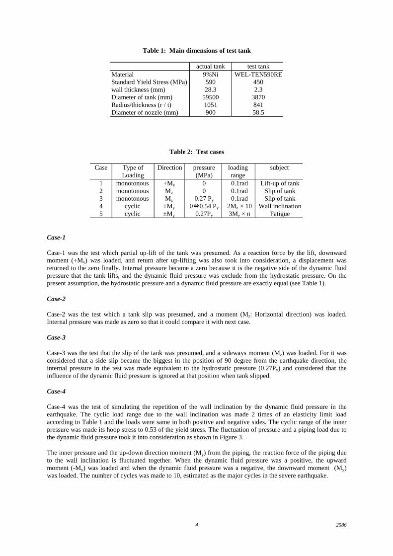
Table 1: Main dimensions of test tank
actual tank test tankMaterialStandard Yield Stress (MPa)wall thickness (mm)Diameter of tank (mm)Radius/thickness (r / t)Diameter of nozzle (mm)
9%Ni59028.3
595001051900
WEL-TEN590RE4502.3
387084158.5
Table 2: Test cases
Case Type ofLoading
Direction pressure(MPa)
loadingrange
subject
12345
monotonousmonotonousmonotonous
cycliccyclic
+My
Mz
Mz
±My
±My
00
0.27 Py
0⇔0.54 Py
0.27Py
0.1rad0.1rad0.1rad
2Me × 103Me × n
Lift-up of tankSlip of tankSlip of tank
Wall inclinationFatigue
Case-1
Case-1 was the test which partial up-lift of the tank was presumed. As a reaction force by the lift, downwardmoment (+My) was loaded, and return after up-lifting was also took into consideration, a displacement wasreturned to the zero finally. Internal pressure became a zero because it is the negative side of the dynamic fluidpressure that the tank lifts, and the dynamic fluid pressure was exclude from the hydrostatic pressure. On thepresent assumption, the hydrostatic pressure and a dynamic fluid pressure are exactly equal (see Table 1).
Case-2
Case-2 was the test which a tank slip was presumed, and a moment (Mz: Horizontal direction) was loaded.Internal pressure was made as zero so that it could compare it with next case.
Case-3
Case-3 was the test that the slip of the tank was presumed, and a sideways moment (Mz) was loaded. For it wasconsidered that a side slip became the biggest in the position of 90 degree from the earthquake direction, theinternal pressure in the test was made equivalent to the hydrostatic pressure (0.27Py) and considered that theinfluence of the dynamic fluid pressure is ignored at that position when tank slipped.
Case-4
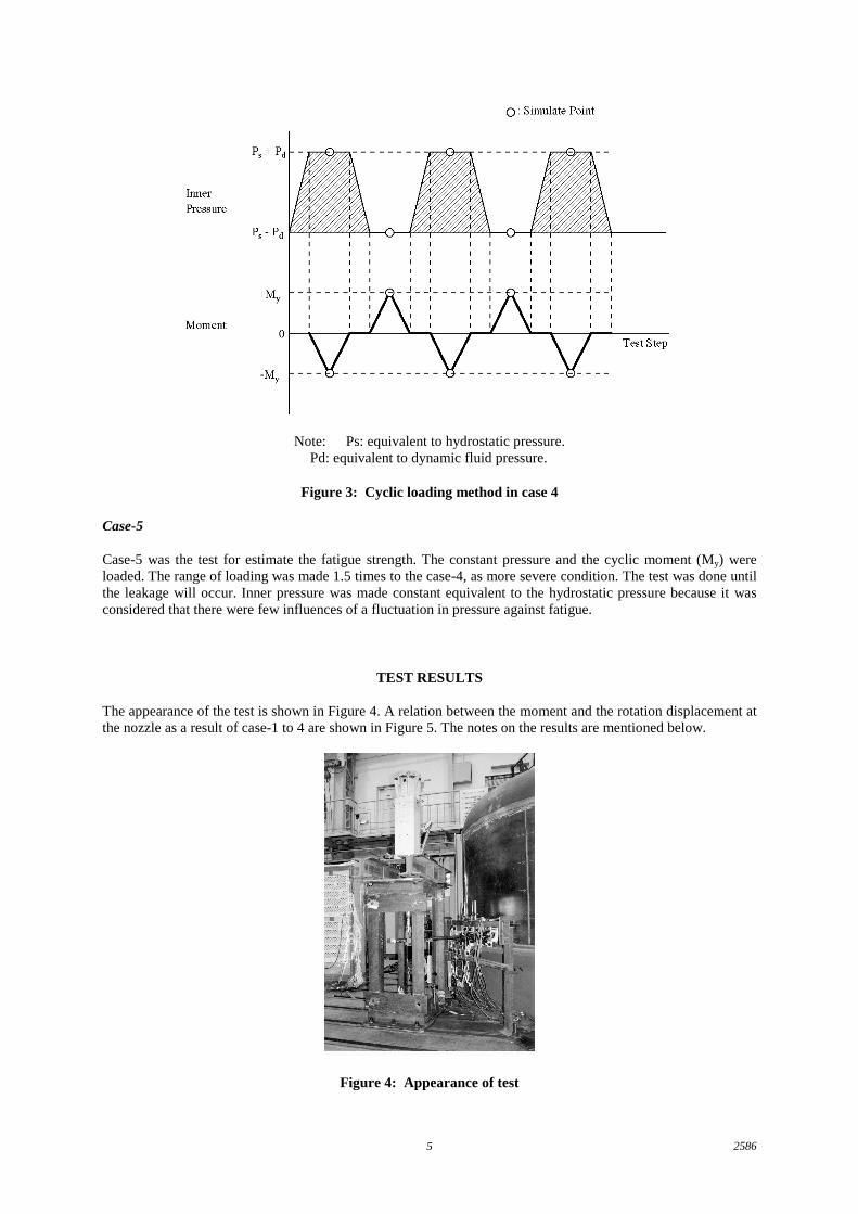
Case-4 was the test of simulating the repetition of the wall inclination by the dynamic fluid pressure in theearthquake. The cyclic load range due to the wall inclination was made 2 times of an elasticity limit loadaccording to Table 1 and the loads were same in both positive and negative sides. The cyclic range of the innerpressure was made its hoop stress to 0.53 of the yield stress. The fluctuation of pressure and a piping load due tothe dynamic fluid pressure took it into consideration as shown in Figure 3.
The inner pressure and the up-down direction moment (My) from the piping, the reaction force of the piping dueto the wall inclination is fluctuated together. When the dynamic fluid pressure was a positive, the upwardmoment (-My) was loaded and when the dynamic fluid pressure was a negative, the downward moment (My)was loaded. The number of cycles was made to 10, estimated as the major cycles in the severe earthquake.
25865
Note: Ps: equivalent to hydrostatic pressure.Pd: equivalent to dynamic fluid pressure.
Figure 3: Cyclic loading method in case 4
Case-5
Case-5 was the test for estimate the fatigue strength. The constant pressure and the cyclic moment (My) wereloaded. The range of loading was made 1.5 times to the case-4, as more severe condition. The test was done untilthe leakage will occur. Inner pressure was made constant equivalent to the hydrostatic pressure because it wasconsidered that there were few influences of a fluctuation in pressure against fatigue.
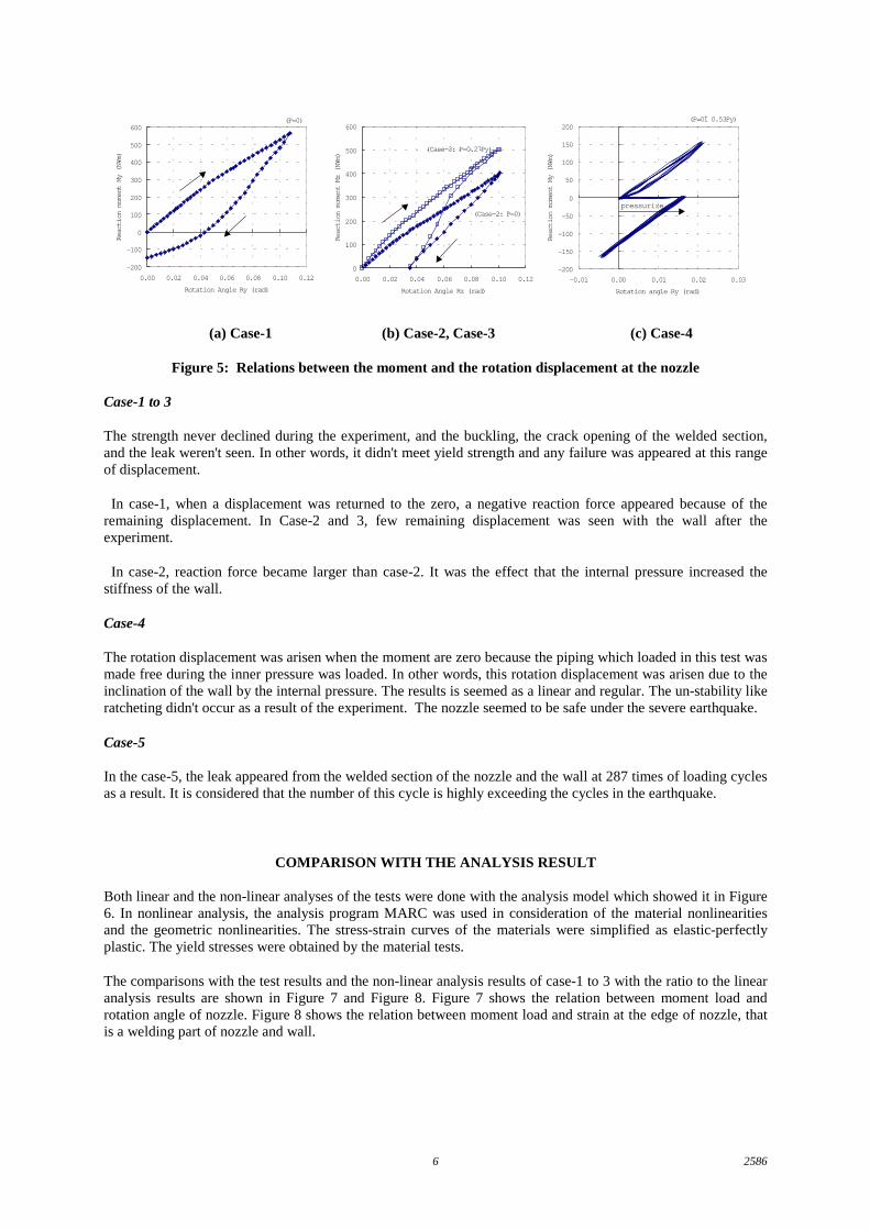
TEST RESULTS
The appearance of the test is shown in Figure 4. A relation between the moment and the rotation displacement atthe nozzle as a result of case-1 to 4 are shown in Figure 5. The notes on the results are mentioned below.
Figure 4: Appearance of test
25866
0
100
200
300
400
500
600
0.00 0.02 0.04 0.06 0.08 0.10 0.12
Rotation Angle Rz (rad)
Reaction moment Mz (N¥m)
(Case-2: P=0)
(Case-3: P=0.27Py)
(P=0)
-200
-100
0
100
200
300
400
500
600
0.00 0.02 0.04 0.06 0.08 0.10 0.12
Rotation Angle Ry (rad)
Reaction moment My (N¥m)
(P=0Ì 0.53Py)
-200
-150
-100
-50
0
50
100
150
200
-0.01 0.00 0.01 0.02 0.03
Rotation angle Ry (rad)
Reaction moment My (N¥m)
pressurize
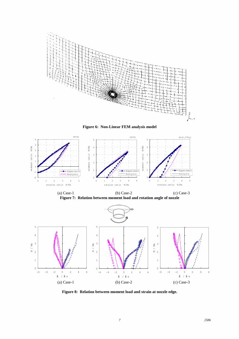
(a) Case-1 (b) Case-2, Case-3 (c) Case-4
Figure 5: Relations between the moment and the rotation displacement at the nozzle
Case-1 to 3
The strength never declined during the experiment, and the buckling, the crack opening of the welded section,and the leak weren't seen. In other words, it didn't meet yield strength and any failure was appeared at this rangeof displacement.
In case-1, when a displacement was returned to the zero, a negative reaction force appeared because of theremaining displacement. In Case-2 and 3, few remaining displacement was seen with the wall after theexperiment.
In case-2, reaction force became larger than case-2. It was the effect that the internal pressure increased thestiffness of the wall.
Case-4
The rotation displacement was arisen when the moment are zero because the piping which loaded in this test wasmade free during the inner pressure was loaded. In other words, this rotation displacement was arisen due to theinclination of the wall by the internal pressure. The results is seemed as a linear and regular. The un-stability likeratcheting didn't occur as a result of the experiment. The nozzle seemed to be safe under the severe earthquake.
Case-5
In the case-5, the leak appeared from the welded section of the nozzle and the wall at 287 times of loading cyclesas a result. It is considered that the number of this cycle is highly exceeding the cycles in the earthquake.
COMPARISON WITH THE ANALYSIS RESULT
Both linear and the non-linear analyses of the tests were done with the analysis model which showed it in Figure6. In nonlinear analysis, the analysis program MARC was used in consideration of the material nonlinearitiesand the geometric nonlinearities. The stress-strain curves of the materials were simplified as elastic-perfectlyplastic. The yield stresses were obtained by the material tests.
The comparisons with the test results and the non-linear analysis results of case-1 to 3 with the ratio to the linearanalysis results are shown in Figure 7 and Figure 8. Figure 7 shows the relation between moment load androtation angle of nozzle. Figure 8 shows the relation between moment load and strain at the edge of nozzle, thatis a welding part of nozzle and wall.
25867
Figure 6: Non-Linear FEM analysis model
(P=0)
-2
-1
0
1
2
3
4
5
0 1 2 3 4 5
rotaion ratio R/Re
modment ratio M/Me
ExperimrntAnalysis
(P=0)
0
1
2
3
4
5
0 1 2 3 4 5
rotaion ratio R/Re
modment ratio M/Me
ExperimentAnalysis
(P=0.27Py)
0
1
2
3
4
5
0 1 2 3 4 5
rotaion ratio R/Re
modment ratio M/Me
Experiment
Analysis
(a) Case-1 (b) Case-2 (c) Case-3Figure 7: Relation between moment load and rotation angle of nozzle
0
1
2
3
4
5
-6 -4 -2 0 2 4 6
ƒÃ / ƒÃ e
M / Me
0
1
2
3
4
5
-6 -4 -2 0 2 4 6
ƒÃ / ƒÃ e
M / Me
0
1
2
3
4
5
-6 -4 -2 0 2 4 6
ƒÃ / ƒÃ e
M / Me
(a) Case-1 (b) Case-2 (c) Case-3
Figure 8: Relation between moment load and strain at nozzle edge.

25868
The analysis results correspond with the test results well. The analysis method seems to be practical.
The relation of deformation and load shown in Figure 7 shows that the tendencies of the tests were seem to becalculated properly except the returning path of case-3. We think this as a future theme.
The relation of strain of the edge of nozzle and load shown in Figure 8 shows that the strain at this part does notincrease even if it exceeds yield strain in both experiment and analysis. We think this is because the plastic hingehave occurred at another part and the stress redistribution have risen. And this stress redistribution is the reasonwhy reaction force never falls down when the deformation exceeds the elasticity limit.
CONCLUSION REMARKS
A series of tests and analyses was concluded as follows.
(1) The major seismic loadings of the nozzles at the bottom in the wall of cylindrical above-ground storage tankunder the severe earthquake are considered as the reaction moments due to wall inclination by the tank dynamicfluid pressure response, slip of the tank and up-lift.
(2) Even if the nozzle in the wall of cylindrical tank is subjected to the displacement loading exceeds theelasticity limit displacement, the reaction force of the nozzle never falls down.
(3) Under the estimated cyclic loading due to dynamic response of the tank, the nozzles are seemed to be safe.
(4) Behavior of nozzle on the cylindrical tank shell is mostly simulated by nonlinear analysis.
ACKNOWLEDGMENTS
The present tests have been planned, and are being pursued, under the committee of Seismic Proving Tests ofEquipment and Structures in Thermal Conventional Power Plant (SPT), established in the Japan PowerEngineering and Inspection Corporation (JAPEIC), with a commission from MITI. Grateful acknowledgement ishereby expressed of invaluable guidance and advice afforded by the above-mentioned committee chaired byEmer. Prof. H. Shibata of the University of Tokyo in planning and conducting the tests.
REFERENCES
Aiba, M., Igarashi, K., Akiyama, H. and Chiba, T.. (1999), "Proving test of nozzles at wall of cylindrical tankunder earthquake", ASME-PVP vol. 387
Higuchi, T., Mori, T., Matsuda, T., Goto, Y., Akiyama, H., Toki, K. and Kobayashi, M. (2000), "SeismicPerformance of LNG Storage Tank Foundations during the Very Large Earthquake", 12WCEE
Nishida, E., Kawamura, K., Maruyama, N., Suzuki, K., Fujita, S. and Chiba, T. (2000), "Proving Test of EnergyAbsorbing Seismic Ties for Aseismic Design of Boiler", 12WCEE
Tanaka, M., Sakurai, T., Ishida, K., Tazuke., H, Akiyama, H., Kobayashi, N. and Chiba, T. (2000), "ProvingTest of Analysis Method on Nonlinear Response of Cylindrical Storage Tank under Sever Earthquake",12WCEE
The High Pressure Gas Safety Institute of Japan (1995), "The Final Report of the Investigation about the GasLeakage from the LP Gas Storage Equipment Caused by Hyogoken-Nanbu Earthquake". (in Japanese)


![PEAD-A09,12,15,18,24,30,36,42AA7 · E Make it as large as possible. About 10 cm [3-15/16 in]. F Indoor unit G Make the piping size large for grouped piping. H Downward slope (1/100](https://img.dokumen.tips/doc/110x75/5fce24884d5b76254e652f52/pead-a0912151824303642aa7-e-make-it-as-large-as-possible-about-10-cm-3-1516.jpg)