Embed Size (px)
Citation preview

TENSILE PROPERTIES AND MICROSTRUCTURAL
CHARACTERIZATION OF Hi-NICALON SiC_BSN COMPOSITES
Ramakrishna.T. Bhatt
NASA Lewis Research Center
21000 Brookpark Road
Cleveland, OH, 44135
The room temperature physical and mechanical properties of silicon carbidefiber-reinforced reaction-bonded silicon nitride matrix composites (SiC/RBSN)
were measured, and the composite microstructure was analyzed. The
composites consist of nearly 24 vol% of aligned Hi-Nicalon SiC fiber yarns in a
-30 vol% porous silicon nitride matrix. The fiber yarns were coated by
chemical vapor deposition with a 0.8ktm layer of boron nitride (BN) followed by
a0.2=ktm layer of SiC. In the as-fabricatedc0ndition, both 1-D and 2-D
composites exhibited high strength and graceful failure, and showed improved
properties when compared with unreinforced matrix of comparable density. Noindication of reaction between the SiC fiber and BN coating was noticed, but the
outer SiC layer reacted locally with the nitridation enhancing additive in theRBSN matrix. A comparison is made between the predicted and measured
values of matrix cracking strength.
1. INTRODUCTION
Reaction-bonded silicon nitride (RBSN) has long been considered a candidate
material for hot section structural components in advanced heat engine
applications 1'2. The main attributes of RBSN are ease of fabrication, near net shape
capability, high creep resistance, high-temperature strength, and low density. In
spite of these advantages, RBSN is not used for commercial applications because of
https://ntrs.nasa.gov/search.jsp?R=20000057283 2020-07-07T17:02:40+00:00Z
4
2
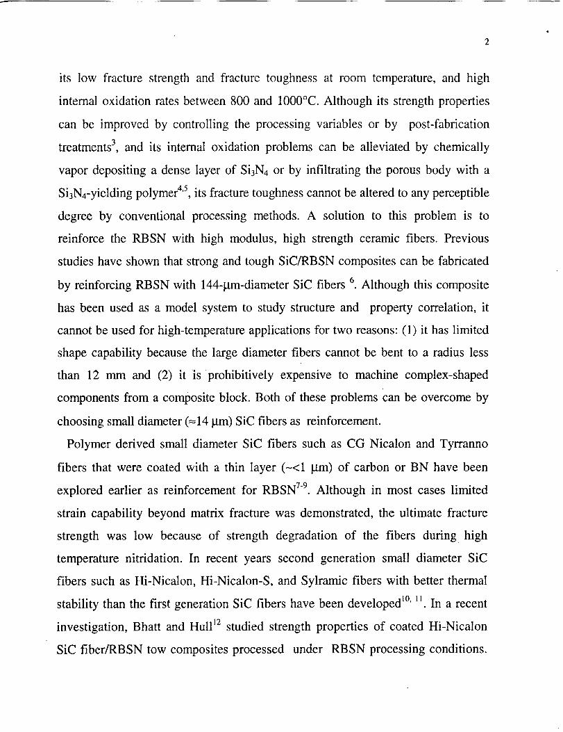
its low fracture strength and fracture toughness at room temperature, and high
internal oxidation rates between 800 and 1000°C. Although its strength properties
can be improved by controlling the processing variables or by post-fabrication
treatments 3, and its internal oxidation problems can be alleviated by chemically
vapor depositing a dense layer of Si3N4 or by infiltrating the porous body with a
Si3N4-yielding polymer 4'5, its fracture toughness cannot be altered to any perceptible
degree by conventional processing methods. A solution to this problem is to
reinforce the RBSN with high modulus, high strength ceramic fibers. Previous
studies have shown that strong and tough SiC/RBSN composites can be fabricated
by reinforcing RBSN with 144-gm-diameter SiC fibers 6. Although this composite
has been used as a model system to study structure and property correlation, it
cannot be used for high-temperature applications for two reasons: (1) it has limited
shape capability because the large diameter fibers cannot be bent to a radius less
than 12 mm and (2) it is prohibitively expensive to machine complex-shaped
components from a composite block. Both of these problems can be overcome by
choosing small diameter (=14 gm) SiC fibers as reinforcement.
Polymer derived small diameter SiC fibers such as CG Nicalon and Tyrranno
fibers that were coated with a thin layer (-<1 lam) of carbon or BN have been
explored earlier as reinforcement for RBSN 7-9. Although in most cases limited
strain capability beyond matrix fracture was demonstrated, the ultimate fracture
strength was low because of strength degradation of the fibers during high
temperature nitridation. In recent years second generation small diameter SiC
fibers such as Hi-Nicalon, Hi-Nicalon-S, and Sylramic fibers with better thermal
stability than the first generation SiC fibers have been developed 1°' I1. In a recent
investigation, Bhatt and Hull 12 studied strength properties of coated Hi-Nicalon
SiC fiber/RBSN tow composites processed under RBSN processing conditions.

Fiber coatings were either pyrolytic boron nitride (PBN), PBN/Si-rich PBN, or
boron nitride (BN)/SiC. This study concluded that all three CVD coated Hi-
Nicalon SiC fibers are stable through the RBSN processing condition, but BN/SiC
coated tow composites yielded greater strength retention than the other two tow
composites.
The objectives of this study were to fabricate BN/SiC coated Hi-Nicalon
SiC/RBSN composites, and to evaluate its room temperature mechanical properties
and characterize its microstmcture.
2. EXPERIMENTAL
2.1. Materials
The SiC fiber yarn (Hi-Nicalon) required for composite fabrication was procured
from Dow Coming Corporation, Midland, MI. A typical fiber yarn contained 500
filaments. The supplier provided information indicates that the diameter of
individual filaments in the yarn varies from 8 to 16 _m, and the average filament
diameter is -14 lam. The as-received fiber yarn had a polyvinyl acetate sizing. The
as-received fiber yarns were coated with a dual layer system of -0.8 _m thick BN
followed by -0.2 _m thick SiC. The coatings were applied by chemical vapor
deposition (CVD) by 3M Corporation, Minneapolis, Minnesota.
2.2. Composite fabrication
The silicon powder required for composite fabrication was obtained from Union
Carbide Corporation, Linde Division, Tonawanda, New York. The as-received
powder was mixed with a nitride enhancing additive, and the mixture was wet
attrition milled in Stoddard solvent (a kerosene-based liquid) for 48h. Attrition
milling was performed in a Si3N4 vessel using Si3N4 grinding media and a

J
4
procedure similar to that used by Herbell et al _3. Attrition milling reduced the
particle size of silicon powder from 23 gm to 0.42 gin, The attrition milled silicon
powder was dried in an oven maintained at 400°C in vacuum for 24h. The dried
powder was stored in a glove chamber until further use.
Composites were fabricated by hot pressing a lay-up of silicon coated fiber mats
to produce a SiC/Si preform and then nitriding the preform at high temperture in
nitrogen. Details of the fabrication are reported by Bhatt and Babuder 14. Here
salient features of the composite fabrication will be described. In the first step, a
silicon slurry was prepared by ball milling appropriate amounts of attrition milled
silicon powder, a polymer binder, a dispersant, and a solvent. The required amount
of the slurry was poured into a slurry tank. In the second step, the Hi-Nicalon SiC
fiber tow was passed through a series of rollers to spread the tows and then into
the tank filled with silicon slurry. The slurry coated fiber tows were wound on a
metal drum at a desired spacing to prepare 150 mm wide fiber mat. After drying in
air, the fiber mat was removed from the drum, and cut into 150 mm x 150 mm
pieces. The cut mat was coated with a 0.5 mm layer of silicon slurry by using a
doctor blade apparatus. The composition of the slurry is similar to that used for the
fiber coating. When dried, the mats were cut into 12 mm wide strips; some mats
were cut parallel and others were cut transverse to the fibers. In the third step,
eleven strips all unidirectional, or alternate strips of unidirectional and transverse
fiber lay-up were stacked in a stainless steel die and pre-pressed at room
temperature. The pre-pressed tapes were hot pressed at 40 MPa at 800°C for 15
min to obtain a SiC/Si preform. Subsequently the preform was nitrided in a tube
furnace using an appropriate nitridation cycle to convert silicon to silicon nitride
matrix. The final dimensions of the specimens after nitriding were 150 mm x 12
mmx 2.5 mm.
5
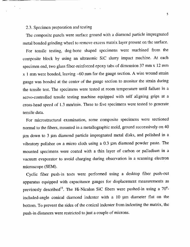
2.3. Specimen preparation and testing
The composite panels were surface ground with a diamond particle impregnated
metal bonded grinding wheel to remove excess matrix layer present on the surface.
For tensile testing, dog-bone shaped specimens were machined from the
composite block by using an ultrasonic SiC slurry impact machine. At each
specimen end, two glass fiber-reinforced epoxy tabs of dimension 37 mm x 12 mm
x 1 mm were bonded, leaving -60 mm for the gauge section. A wire wound strain
gauge was bonded at the center of the gauge section to monitor the strain during
the tensile test. The specimens were tested at room temperature until failure in a
servo-controlled tensile testing machine equipped with self aligning grips at a
cross-head speed of 1.3 mm/min. Three to five specimens were tested to generate
tensile data.
For microstructural examination, some composite specimens were sectioned
normal to the fibers, mounted in a metallographic mold, ground successively on 40
pm down to 3 _m diamond particle impregnated metal disks, and polished in a
vibratory polisher on a micro cloth using a 0.3 _tm diamond powder paste. The
mounted specimens were coated with a thin layer of carbon or palladium in a
vacuum evaporator to avoid charging during observation in a scanning electron
microscope (SEM).
Cyclic fiber push-in tests were performed using a desktop fiber push-out
apparatus equipped with capacitance gauges for displacement measurements as
previously described _5. The Hi-Nicalon SiC fibers were pushed-in using a 70 °-
included-angle conical diamond indenter with a 10 _tm diameter flat on the
bottom. To prevent the sides of the conical indenter from indenting the matrix, the
push-in distances were restricted to just a couple of microns.
6
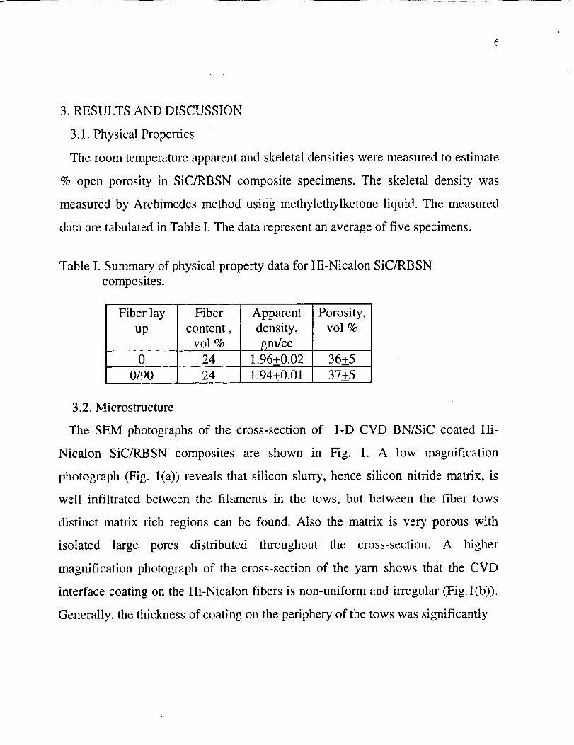
3. RESULTS AND DISCUSSION
3.1. Physical Properties
The room temperature apparent and skeletal densities were measured to estimate
% open porosity in SiC/RBSN composite specimens. The skeletal density was
measured by Archimedes method using methylethylketone liquid. The measured
data are tabulated in Table I. The data represent an average of five specimens.
Table I. Summary of physical property data for Hi-Nicalon SiC/RBSN
composites.
Fiber lay
up
Fiber
content,vol %
Apparent
density,
grn/cc
! .96+0.02
Porosity,vol %
3.2. Microstructure
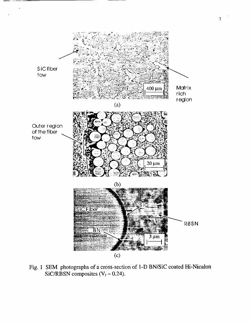
The SEM photographs of the cross-section of 1-D CVD BN/SiC coated Hi-
Nicalon SiC/RBSN composites are shown in Fig. 1. A low magnification
photograph (Fig. l(a)) reveals that silicon slurry, hence silicon nitride matrix, is
well infiltrated between the filaments in the tows, but between the fiber tows
distinct matrix rich regions can be found. Also the matrix is very porous with
isolated large pores distributed throughout the cross-section. A higher
magnification photograph of the cross-section of the yarn shows that the CVD
interface coating on the Hi-Nicalon fibers is non-uniform and irregular (Fig. l(b)).
Generally, the thickness of coating on the periphery of the tows was significantly
0 24 36+5
0/90 24 1.94+0.01 37+5
SiC fiber
tow
(a)
[V_rix
rich
region
Outer regionof the fiber
tow
(b)
20 _m
RBSN
Fig. 1
(c)
SEM photographs of a cross±section of 1-D BN/SiC coated Hi-Nicalon
SiC/RBSN composites (Vf - 0.24).

greater than in the interior of the tows. Figure 1 (c) is a photograph of a single SiC
filament showing the BN/SiC interface. The darker ring around the fiber is the BN
coating and the grayish ring on top of the BN is the SiC coating. The BN coating
appears to be uniform, but the SiC coating is generally nodular and rough. TEM
analysis of the interface indicates (photographs not shown) that the BN coating is
amorphous, and that the SiC coating is crystalline and composed of columnar
grains. Figures l(a) and (b) show that the majority of the RBSN matrix and SiC
outer coating interface showed no reaction, but local areas of reaction are present.
TEM revealed that the nitride enhancing additive in the RBSN matrix locally
reacted with the SiC coating.
3.3. Mechanical behavior of laminated composites
Typical room temperature tensile stress-strain behaviors of [0110 and [0/90]s
BN/SiC coated Hi-Nicalon SiC/RBSN composites (-24 vol%) are shown in Fig. 2.
Included in the figure is the tensile stress-strain behavior of the monolithic RBSN
matrix fabricated under similar conditions. The stress-strain curve of both 1-D and
2-D reinforced BN/SiC coated Hi-Nicalon SiC/RBSN composites showed two
distinct regions: an initial linear region followed by a non-linear region. At
ultimate load the composite specimens failed abruptly. In contrast, the stress-strain
curve of monolithic RBSN showed only one initial linear region. Also noticed is
that the strain capability of both 1-D and 2-D composites is significantly greater
than that of the monolithic RBSN. The tensile data are summarized in Table II.
The data represent average of 3 to 5 tests.
Figure 3 shows the fracture surface of 1-D BN/SiC coated Hi-Nicalon
SiC/RBSN composites. It is obvious from the figure that the composites exhibit a
significant amount of fiber pull out, typical of a tough composite. Examination of
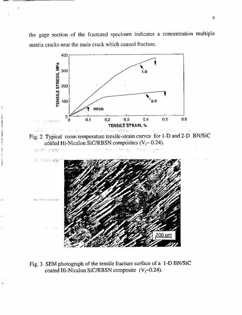
the gage section of the fractured specimen indicates
matrix cracks near the main crack which caused fracture.
a concentration multiple
400
g.300
200
_100
00
1-D
_SN I , , I r
0.1 0.2 0.3 0.4 0.5
TENSILE STRAIN, %
Fig. 2 Typical room temperature tensile-strain curves for 1-D and 2-D BN/SiCcoated Hi-Nicalon SiC/RBSN composites (Vf- 0.24).
. .. : :-. ::: • . ,_
Fig. 3 SEM photograph of the tensile fracture surface of a 1-D BN/SiC
coated Hi-Nicalon SiC/RBSN composite (Vf-0.24).
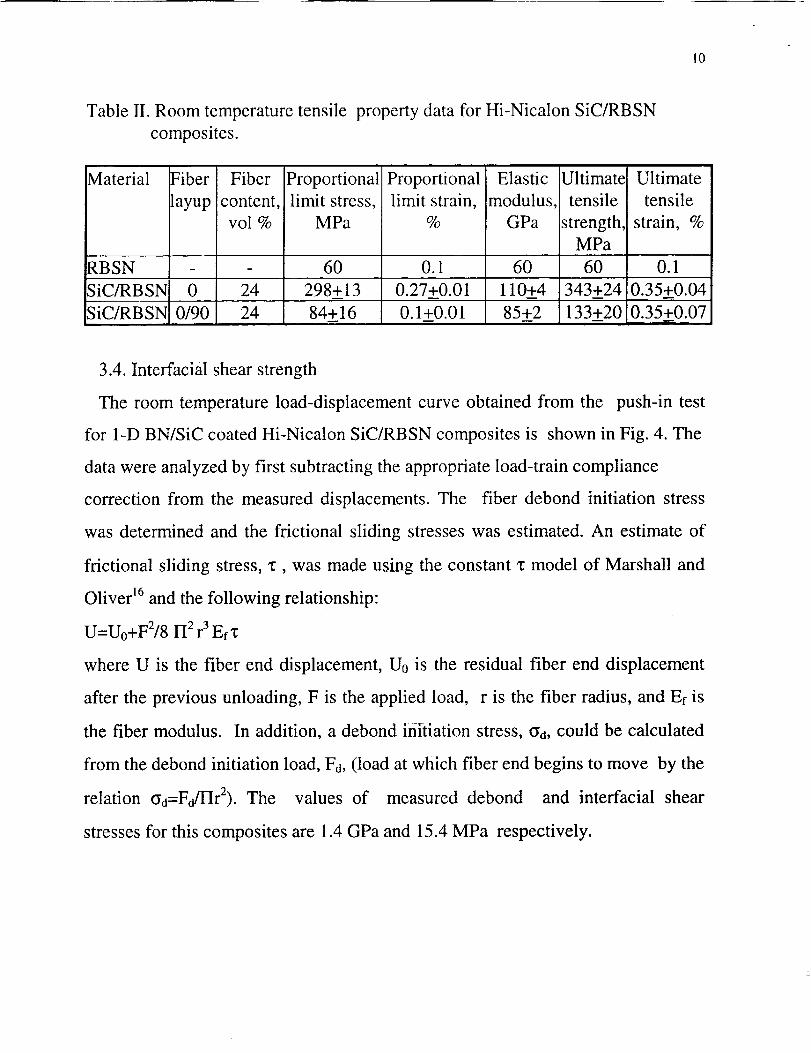
Table lI. Room temperature tensile property data for Hi-Nicalon SiC/RBSN
composites.
10
Material Fiber
layup
RBSN
SiC/RBSN 0
SiC/RBSN 0/90
Fiber
content,vol %
24
24
Proportional
limit stress,MPa
6O
298+13
84+16
Proportional
limit strain,%
0.1
0.27+0.010.1+0.01
Elastic
modulus,GPa
60
110+4
85+2
Ultimate
tensile
strength,MPa
6O
343+24
133+20
Ultimate
tensile
strain, %
0.1
0.35+0.04
0.35+0.07
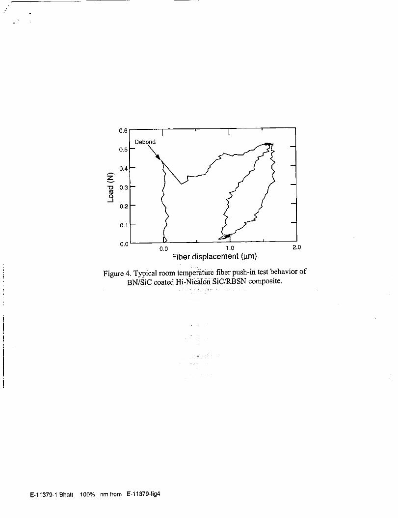
3.4. Interracial shear strength
The room temperature load-displacement curve obtained from the push-in test
for 1-D BN/SiC coated Hi-Nicalon SiC/RBSN composites is shown in Fig. 4. The
data were analyzed by first subtracting the appropriate load-train compliance
correction from the measured displacements. The fiber debond initiation stress
was determined and the frictional sliding stresses was estimated. An estimate of
frictional sliding stress, "c, was made using the constant "cmodel of Marshall and
Oliver 16and the following relationship:
U=U0+F2/8 gl 2 r 3 Erx
where U is the fiber end displacement, U0 is the residual fiber end displacement
after the previous unloading, F is the applied load, r is the fiber radius, and Ef is
the fiber modulus. In addition, a debond initiation stress, oa, could be calculated
from the debond initiation load, Fa, (load at which fiber end begins to move by the
relation oa=FdI-lr2). The values of measured debond and interfacial shear
stresses for this composites are 1.4 GPa and 15.4 MPa respectively.

11
z
"I0
0..I
0.6
0.5
0.4
0.3
0.2
0.1
0.0
debond
I ' I
\
0.0 1.0
Fiber Displacement (l_m)
>
2.0
Fig. 4 Typical room temperature fiber push-in test behavior of BN/SiC coated
Hi-Nicalon SiC/RBSN composite.
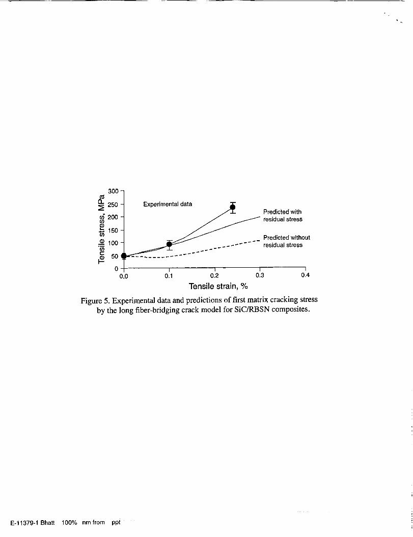
3.5. Matrix cracking strength prediction
A fiber bridging crack model developed by Aveston, Cooper, and Kelly _7 was
used to predict the matrix cracking strength in SiC/RBSN composites. For this
calculation the following values of Ef=270 GPa, Era= 60 GPa, Fm (matrix fracture
energy) =36 J/m 2, 13_f=3.8x10 -6, C(m =5.4x10 -6, 1; = 15 MPa, AT=1175 and
R=7xl0 -6 m were used. The variation of matrix cracking strength with fiber
fraction was predicted with and without accounting for thermal residual stresses.
Results are compared with the measured values in Fig. 5. The plot indicates that
the predicted values agree with the measured values.

12
_- 3OO
250200
150
=._ 100_ 50C_ 0I.--
Predicted with
residual stress
Predicted withouresidual stress
0
I I I 1
0.1 0.2 0.3 0.4
Tensile Strain, %
Fig. 5 Experimental data and predictions of first matrix cracking stress by the
long fiber-bridging crack model for SiC/RBSN composites.
4. CONCLUSIONS
A strong and tough RBSN can be fabricated by using BN/SiC coated Hi-Nicalon
SiC fibers. Further improvements in composite properties are possible by
controlling fiber fraction, and processing variables.
ACKNOWLEDGEMENTS
I would like to thank Dr. Jeffrey Eldridge for performing interfaciaI shear
strength measurements and T.A. Leonhardt for preparing the ceramographic
specimens

13
REFERENCES
1) F.L. Riley, Nitrogen Ceramics (Noordhoff, Leyden, 1977).
2) E.M. LENOE, R.N. KATZ and J.J. BURKE, Ceramics for High
Performance Applications, Vol. III (Plenum, New York, London, 1979).
3) J.A. MANGELS and G.J. TENNENHOUSE, Bull. Am. Ceram. Soc. 59
[2](1980)1216.
4) O.J. GREGORY and M.H. RICHMAN, J. Amer. Ceram. Soc. 67(1984) 335.
5) S. KLEBER and J. H. WEISS, J. Euro. Ceram. Soc. 10(1992)205.
6) R.T. BHATT, U.S. Patent No. 4689188 (1987).
7) J.W. LUCEK, G.A. ROSSETTI, Jr., and S.D. HARTLINE, Stability of
continuous Si-C(-O) reinforcing elements in reaction-bonded silicon nitride
process environments, in: Metal Matrix, Carbon, and Ceramic Matrix
Composites 1985, NASA CP-2406, ed. J.D. Buckley, NASA, Washington,D.C.,1985.
8) T.L. STARR, D.L. MOHR, W.J. LACKEY, and J.A. HANIGOFSKY, Ceram.
Eng. Sci. Proc., 14 [9-10] 1125-1132 (1993).
9) G.H. WOBLEWSKA and G. ZIEGLER, Ceramic Trans. 58, 131-136 (1995).
10) M. TAKEDA, Y. IMAI, H. ICHIKAWA, T. ISIKAWA, N. KASAI,
T. SEGUCHI, and K. OKAMURA, Ceram. Eng. Sci. Proc., 13 (7-8), 209-217
(1992).
11) J.B. HURST, D. GORICAN, and H.M. YUN, Ceramic Trans. 58, 131-136
(1995).
12) R.T. BHATT and D.R. HULL, Effects of fiber coatings on tensile properties of

14
Hi-Nicalon SiC/RBSN tow composites, NASA TM-113170, NASA,
Washington, D.C. 1997.
13) T.P. HERBELL, T.K. GLASGOW and N.W. ORTH, Bull. Amer. Ceram. Soc.
63 [9](1984) 1176.
14) R.T. BHATT and R. BABUDER, Processing and properties of Hi-Nicalon
SiC/RBSN composites, NASA TM (in press).
15) J.I. ELDRIDGE, Desktop fiber push-out apparatus, NASA TM-105341,NASA, Washington, D.C., 1991.
16) D.B. MARSHALL and W.C. OLIVER, Mater. Sci. Eng. A, 126, 95-103
(1990).
17) J. AVESTON, G. COOPER, and A. KELLY, Single and multiple fracture, in:
The Properties of Fiber Composites (Conference Proceedings, National
Physical Laboratory, Guildford) IPC Science and Technology Press Ltd., 1971.
[5
Please make following corrections to the authors proof.
(1) Page 1, right column, last sentence: a period after (BN)/SiC.
(2) Page 3, second column heading of the Table I should read Fiber content (vol
%__L.(3) Page 4, third column heading of the Table II should read Fiber content
(vol%).
(4) Page 5, left column: delete the forth line.
(5) Suggested keywords list: A.Tape casting/hot pressing. B. Composites. C.
Mechanical properties. D.SiC/Si3N4. E. Structural applications

Outer regionof the fiber
tow
(a)
Matrix
rich
region
(b)
RBSN
(c)
Figure l. SEM photographs of a cross-section of 1-D BN/SiC coated
Hi-Nicalon SiC/RBSN composites (Vf ~ 0.24).
E-11379-1 Bhatt 100% nm PhE from E-11379 fig 1 from author

4OO
n 300
o9
ffli- 100
!-
0 0 0.6
1-D
_, I , I , I I _ I
0.1 0.2 0.3 0.4 0.5
Tensile strain, %
Figure 2. Typical room temperature tensile-strain curves for 1-D and 2-DBN/SiC coated Hi-Nicalon SiC/RBSN composites (Vf- 0.24).
E-11379-1Bhatt 100% nmfrom E-11379-fig2

Figure 3. SEM photographs of the tensile fracture surface of a 1-D
BN/SiC coatedHi-Nicalon SiC/RBSN composites (Vr ~ 0.24).
E-11379-1 Bhatt 100% nm PhE from E-11379 fig 3 from author
Zv
o,
0.6
0.5
0.4
0.3
0.2
0.1
I ' I
0,0 ! I
0.0 1.0 2.0
Fiber displacement (pm)
Figure 4. Typical room temperature fiber push-in test behavior ofBN/SiC coated Hi-Nicalon SiC/RBSN composite.
E-11379-1 Bhatt 100% nmfrom E-11379-fig4
£L
(/)
(/)
_.e
300 -
250 -
20O
150
100
5O 4
0-
0.0
Expedmental data
Predicted with
residual stress
Predicted without
residual stress
I I I I
0.1 0.2 0.3 0.4
Tensile strain, %
Figure 5. Experimental data and predictions of first matrix cracking stress
by the long fiber-bridging crack model for SiC/RBSN composites.
E-11379-1 Bhatt 100% nm from ppt