Embed Size (px)
Citation preview

1
Tensile Behaviour of Textile Reinforcement under Accelerated Ageing Conditions
Natalie Williams Portal, Ph.D.1, Mathias Flansbjer, Adj. Prof.2, Pär Johannesson, Ph.D.3, Katarina Malaga, Adj. Prof.4, Karin Lundgren, Prof.5
1CBI Swedish Cement and Concrete Research Institute, Borås, SE-501 15, Sweden, and Dept. of Civil and Environmental Engineering, Chalmers University of Technology, Gothenburg 412 96, Sweden E-mail: [email protected]
2SP Technical Research Institute of Sweden, Borås, SE-501 15, Sweden, and Dept. of Civil and Environmental Engineering, Chalmers University of Technology, Gothenburg 412 96, Sweden E-mail: [email protected]
3SP Technical Research Institute of Sweden, Gothenburg, SE-400 22, Sweden, E-mail: [email protected]
4CBI Swedish Cement and Concrete Research Institute, Borås, SE-501 15, Sweden, E-mail: [email protected]
5Dept. of Civil and Environmental Engineering, Chalmers University of Technology, Gothenburg 412 96, Sweden, E-mail: [email protected]
Abstract:
Textile Reinforced Concrete (TRC) has emerged as a promising alternative wherein
corrosion is no longer an issue and much thinner and light-weight elements can be designed.
Although TRC has been expansively researched, the formalization of experimental methods
concerning durability arises when attempting to implement and design such innovative
building materials. In this study, accelerated ageing tests paired with tensile tests were
performed. The change in physico-mechanical properties of various commercially available
textile reinforcements was documented and evaluated. The ability for the reinforcements to
retain their tensile capacity was also quantified in the form of empirical degradation curves. It
was observed that accelerated test parameters typically applied to fibre-reinforced polymer
(FRP) bars and grids are generally too aggressive for the textile reinforcement products and
alternative boundary conditions are necessary. The developed degradation curves were
found to have an overall good correlation with the experimental findings.
Keywords: Textile reinforced concrete; accelerated ageing; tensile testing; experimental tests; durability.
2
1. Introduction
Textile reinforced concrete (TRC) not only presents sustainable advantages [1] but has also
been found to be a suitable material for structures such as thin cladding and sandwich
elements [2, 3]. These alternative reinforcement materials are typically made of alkali-
resistant (AR) glass, basalt or carbon fibres and offer a much lower density (1800-
3000 kg/m3) in comparison to steel reinforcement bars (7850 kg/m3) which further contributes
to a reduction in dead weight. Nonetheless, questions regarding the long-term durability arise
when attempting to design and implement new building materials such as TRC, as there is
minimal long-term performance or durability data available [4, 5].
TRC can be generally characterized as a three-phase material consisting of a cementitious
matrix, fibre-yarn structure as well as a fibre-matrix interface. This heterogeneous material
can be exposed to various degradation processes over its service life, such as fibre
degradation due to chemical attack, fibre-matrix interfacial physical and chemical
interactions, and volume instability and cracking [6]. These degradation processes can occur
individually or simultaneously which in turn makes the characterization of the long-term
performance of fibre-based composites complex. Another aspect which is critical to
understand is that fibre-based reinforcement materials are marked by small surface defects
or weak zones resulting from production and handling processes [7]. These defects have
been found to be one of the factors contributing to strength loss of the final reinforcement
product. Particularly concerning glass fibres, these weak zones have been observed to
consequently grow when exposed to sustained loading conditions as a result of a
mechanism called static fatigue or delayed failure [7, 8]. The static fatigue strength of the
composite is related to the critical flaw size, stress level and exposure conditions which
govern the crack growth rate of surface defects [9].
Individual fibres incorporated in the yarns which form the textile reinforcement grid are
typically composed of a sizing material applied during production which serves primarily as a
3
surface protection [10]. This applied sizing could greatly influence the degradation process
and long-term performance of the composite [11-13], particularly concerning AR-glass and
basalt fibres. During the service life, TRC and the reinforcement could face such boundary
conditions like the high alkalinity of the concrete pore water (peak during hydration), varying
temperature and humidity loads, carbonation as well as sustained and cyclic loading and
fatigue which could all have an effect on its long-term mechanical behaviour. As such, the
critical zones of degradation will most likely be the fibre sizing-coating and the fibre-matrix
interface.
Durability performance is most accurately measured in real-time [5]; however, typically
having time as a constraint, accelerated ageing tests [6] or experimentally calibrated models
[10] have been used to predict the long-term performance of textile reinforcement, fibres or
fibre-reinforced polymers (FRP) in a cementitious matrix. A common method to accelerate
the ageing of fibres in the form of FRP rods or textile reinforcement consists of immersing
them in a simulated or actual concrete pore solution, i.e. alkaline environment, while
simultaneous being exposed to high temperature [10, 14]. For instance, this method has
been used to measure the loss of tensile strength exclusively due to the so-called chemical
corrosion process related to AR-glass textile reinforcement [15]. Alternatively, basalt or glass
fibre yarns have been immersed in sodium hydroxide (NaOH) and hydrochloric acid (HCl)
solutions for varying time periods [16] or 3-ionic solutions to target localized attack [17, 18].
Electron-microscopes have commonly been applied to investigate the degradation phases of
the fibre-yarn surface [18] or the fibre-yarn-matrix interface [13]. Accelerated ageing of textile
reinforcement cast in concrete has also been conducted in climate chambers at varying
temperatures or moisture conditions followed by the quantification of loss of tensile strength
and bond through various mechanical tests [4, 13, 19, 20]. A time-dependent model was
even developed and calibrated to determine the strength loss of AR-glass textile
reinforcement in TRC [21-23], which was thereafter applied to design a pedestrian bridge
[24]. Although a number of accelerated tests have been reported in this field of study,
4
researchers have applied varying experimental methods and have investigated differing
materials making them subjective and to some degree non-comparable.
2. Research significance
In this study, accelerated tests paired with direct tensile tests were performed according to
ISO 10406-1 [25] pertaining to fibre-reinforced polymer (FRP) bars and grids. It was of key
interest to forecast the so-called long-term mechanical behaviour and material degradation of
various commercially available textile reinforcement products for potential use in new façade
solutions. Alternative boundary conditions were also included in the scope of work to
investigate the discrete influence of two key variables on material ageing, i.e. temperature
and pH of a simulated pore solution. The change in physico-mechanical properties of the
various textile reinforcements was documented and evaluated in this work. The ability for the
reinforcement materials to retain their tensile capacity was also quantified in the form of
empirical degradation curves. The study also included development of methods for
preparation of end anchorage, gripping system to the testing machine and measurement of
strain up to failure.
3. Experimental program
3.1 Textile reinforcement
AR-glass, basalt and carbon textile reinforcement grids primarily selected based on the
current availability of commercial products were investigated. TRC building applications have
primarily focused on the use of AR-glass and carbon fibre materials, but natural and polymer
fibres have also been researched for this application [5]. The use and durability of AR-glass
has been deeply investigated for use in TRC as it has been both cost effective and readily
available [21]. Alternatively, basalt fibres, mineral fibres extracted from volcanic rock, are
often compared to glass fibres, such as E-glass and AR-glass, due to existing similarities in
their chemical composition [11, 16, 26]. Regarding carbon fibre materials, the price per
square meter of product is still significantly higher than the other alternatives, which is
5
primarily because it is still most commonly demanded in other industries such as automotive
and aerospace. General material and mechanical properties are commonly provided by the
textile reinforcement producers, such as those data presented in Table 1, and at times also
including the modulus of elasticity and elongation. The methods used to obtain the
mechanical properties vary based on the source, which could decrease the soundness of the
available data. Even so, tensile testing of these reinforcement materials was conducted
according to the standard method stated in ISO 10406-1 [25] to base further evaluations in
this study on these obtained data.
Table 1: General properties of the studied reinforcement materials.
Material (Product/Supplier)
Coating Grid Spacing 0°/90° [mm]
Weight [g/m2]
Tensile Strength of Yarn [N]
AR-glass (Glasfiberväv Grov), Sto Scandinavia AB
Styrene-butadiene resin (SBR), 20 %
7/8 210 >400
Basalt (Mesh-10-100), Sudaglass Fiber Technology Inc.
Undisclosed resin, 17 %
10/10 165 1152
Carbon (SIGRATEX Grid 250-24), SGL Group
Styrene-butadiene resin (SBR), 15 %
17/18 250 4243
3.2 Test specimen preparation
The mechanical properties and durability of the selected textile reinforcement materials were
investigated. Specimen preparation and test methods provisioned in ISO 10406-1 [25] were
applied to determine the tensile capacity, tensile rigidity and ultimate strain of the textile
reinforcement alternatives pre- and post-immersion into an alkaline solution. The textile
reinforcement, initially in the form of a grid, was cut into so-called individual yarns with a
remaining 2 mm projection of the cross-points (crossbars) as well as more than three cross-
points along the length.
The method applied for gripping the specimens in tensile tests is known to be crucial for the
test results, and various methods have previously been evaluated for tensile tests of FRP-
bars [27]. The method must be suitable for the given specimen geometry while transmitting
6
only the tensile force along the longitudinal axis of the specimens. It should also be ensured
that premature failure of the specimen does not take place in the grip zone which is an
undesirable failure mode. Accordingly, various types of end anchorage were evaluated in this
study which led to the conclusion that an aluminium tube with epoxy resin was the most
suitable method as it allows for the tensile force to be transmitted to the specimen by shear
stress within the epoxy. Other gripping methods, such as clamp-to-yarn, emery cloth, rubber
sheets and aluminium tabs were found to underestimate the tensile strength of the material
which resulted in the specimens to either slide out of the test grip or fail within the grip.
The aluminium tubes used as end anchorage had a length ranging from 75-100 mm, outer
diameter of 15 mm and inner diameter of 12 mm. The inside of the tubes were roughened
and cleaned with acetone to achieve superior bonding with the epoxy. An epoxy resin with 10
% sand filler (NM Injection 300, Nils Malmgren AB) was used. A special device was
developed to keep the specimens and the tubes concentrically and vertically aligned during
the epoxy setting, such that 14 specimens could be prepared simultaneously. The specimen
ends were prepared in two phases; one end was firstly cast in the aluminium tube followed
by a 24 h hardening period of the epoxy, thereafter the specimen was upturned and the
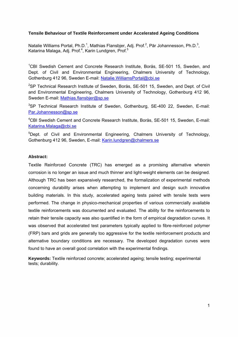
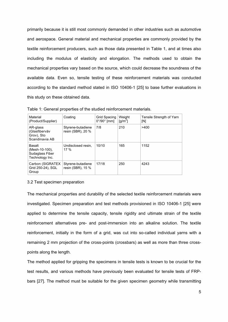
second end was prepared using the same procedure. The total specimen length was 500
mm and the end anchorage length, Le, was 75 – 100 mm on either side of the specimen as
depicted in Figure 1. The tested length, L, was set to 300 – 350 mm which meets the
minimum specified length of ≥ 300 mm. In addition, the gauge length of the extensometer
measuring the strain, Lg, was 100 mm.
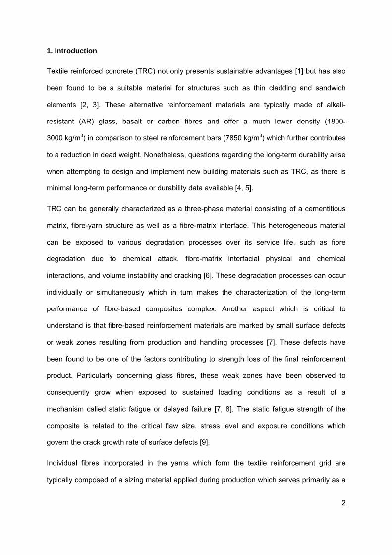
Figure 1
3.3 Ten
Tensile
carried
recorde
deforma
techniqu
approxi
cross-p
the defo
directly.
risk of d
linear e
samplin
anchora
MPa wa
by a for
needed
measur
1. Geometry
sile strengt
strength te
out using
ed by a load
ation was
ue as illus
mately 100
ins. A great
ormation u
. A mechan
damage, th
lasticity. Th
ng rate of 2
ages in the
as applied t
rce of 20 N
to adequa
rements. Th
y and layou
th test
ests were
a universa
d cell with a
measured
strated in
0 mm as pr
t advantage
p to failure
nical extens
ereby caus
he force and
20 Hz. The
convention
to the anch
N; however,
ately straigh
he tests we
ut of a tensil
conducted
al testing m
a rated capa
by a Mes
Figure 2.
reviously m
e of using a
e of the sp
someter mo
ing the ultim
d deformatio
e load was
al hydraulic
horage at b
in certain c
hten out the
ere controll
le test spec
in accorda
machine (S
acity of 10 k
ssphysik V
The mea
mentioned a
a video exte
ecimen, i.e
ost often ha
mate strain
on were rec
s introduce
c grips of th
oth ends. T
cases a lar
e specimen
led by the
cimen with e
ance with I
Sintech Mod
kN and an a
Videoextens
asuring ga
and was ma
ensometer is
e. the ultim
as to be re
to be extra
corded in a
d to the s
he testing m
The specim
rger preload
ns in order
cross-head
end anchora
SO 10406-
del 20/D) a
accuracy be
ometer ME
uge length
arked by tw
s that it is p
ate strain c
moved befo
apolated by
data acquis
pecimen by
machine. A c
ens were g
d of approx
to obtain c
d displacem
age.
-1. The tes
and the fo
etter than 1
E46 with b
h was cho
wo referenc
possible to m
can be det
fore failure
y the assum
sition syste
y gripping
clamp press
generally pr
ximately 100
correct defo
ment of 3 m
7
sts were
rce was
%. The
backlight
osen as
ce metal
measure
termined
to avoid
mption of
m with a
the end
sure of 4
reloaded
0 N was
ormation
mm/min,
corresp
average
test sam
conditio
Figure 2
3.4 Alka
The alk
[25]. Th
parts cu
±3°C fo
pore so
could fa
standar
(KOH)
approxi
The lin
infiltratio
onding to a
e temperatu
mples of ea
ons.
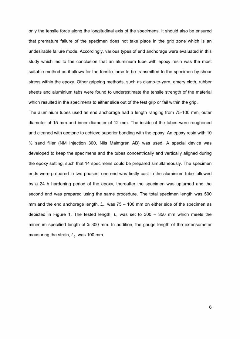
2. Overview
ali resistanc
kali resistan
he test cons
ut away in
r 30 days. T
olution of co
ace when
rd consists
in 1 l of
mately pH 1
ear test pi
on of the s
a strain rate
ure during t
ach reinforc
w of the tens
ce test
ce of the re
sists of imm
an alkaline
The prepare
oncrete in o
embedded
of 8.0 g of
deionized
14.
ieces were
solution. Th
of approxim
testing was
cement mat
sile test setu
einforcemen
mersing line
solution (p
ed alkaline
order to sim
in a conc
sodium hy
water. The
e bundled
he linear tes
mately 5 x
measured
terial were
up and refe
nts was als
ear pieces o
pH>13) whi
solution sho
mulate the e
crete matrix
ydroxide (Na
e alkalinity
and sealed
st pieces w
10-3/min wit
to be 25°C
conducted
rence meta
so investiga
of textile re
le being ex
ould have a
nvironment
x. The alka
aOH) and 2
of this so
d by epoxy
were therea
thin the mea
C. Tensile te
for pre- an
al cross-pins
ted accordi
einforcing gr
xposed to a
a similar pH
in which te
aline solutio
22.4 g of po
olution was
y resin end
after immer
asuring len
ests of at le
nd post- im
s.
ing to ISO
rid with ext
a temperatu
H value to th
extile reinfo
on provided
otassium hy
s measure
d caps to
rsed in the
8
gth. The
east five
mmersion
10406-1
traneous
ure of 60
hat of the
orcement
d in the
ydroxide
d to be
prevent
alkaline
solution
sealed
and 30
remove
visually
testing.
immers
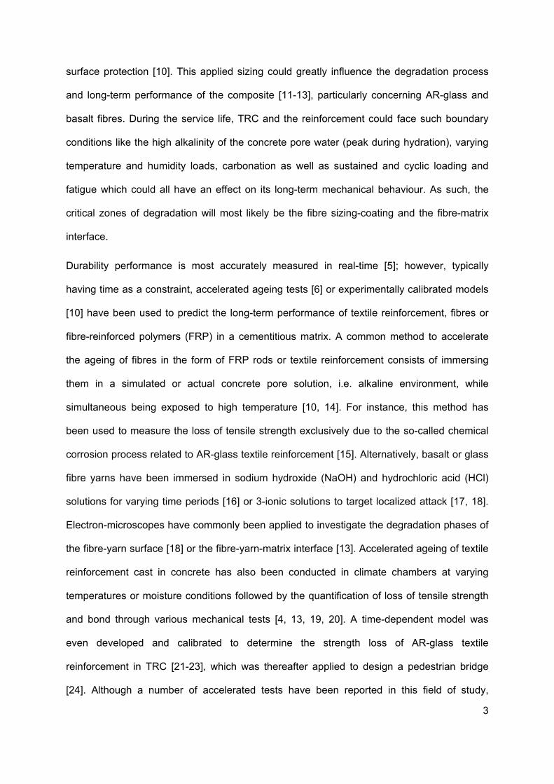
Figure 3
One ma
quantific
compar
the bou
reinforc
not be s
process
water (p
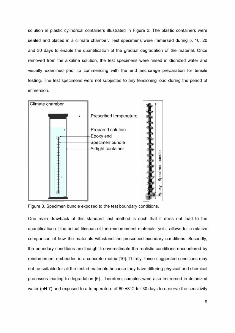
n in plastic
and placed
days to en
d from the
examined
The test s
ion.
3. Specimen
ain drawba
cation of th
rison of how
undary cond
ement emb
suitable for
ses leading
pH 7) and e
cylindrical
d in a clima
nable the q
alkaline so
prior to c
pecimens w
n bundle ex
ack of this
e actual life
w the mate
ditions are t
bedded in a
all the teste
to degrada
exposed to
containers
ate chambe
quantificatio
olution, the
commencing
were not su
xposed to th
standard
espan of the
erials withst
thought to o
a concrete m
ed materials
ation [6]. Th
a temperat
illustrated
er. Test spe
n of the gr
test specim
g with the
ubjected to
he test boun
test metho
e reinforcem
tand the pre
overestimat
matrix [10].
s because
herefore, sa
ure of 60 ±
in Figure 3
ecimens we
radual degr
mens were
end anch
any tensio
ndary condi
od is such
ment mater
escribed bo
te the realis
Thirdly, the
they have d
amples wer
3°C for 30
3. The plast
re immerse
radation of
rinsed in d
orage prep
ning load d
tions.
that it doe
rials, yet it a
oundary co
stic conditio
ese sugges
differing phy
re also imm
days to obs
tic containe
ed during 5
the materia
dionized wa
paration for
during the p
es not lead
allows for a
onditions. S
ons encoun
sted conditio
ysical and c
mersed in d
serve the se
9
ers were
5, 10, 20
al. Once
ater and
r tensile
period of
d to the
a relative
econdly,
tered by
ons may
chemical
eionized
ensitivity
of the f
were ex
alkaline
shown
carried
referred
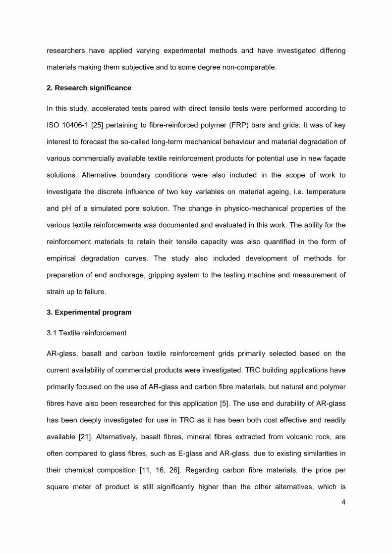
Figure 4
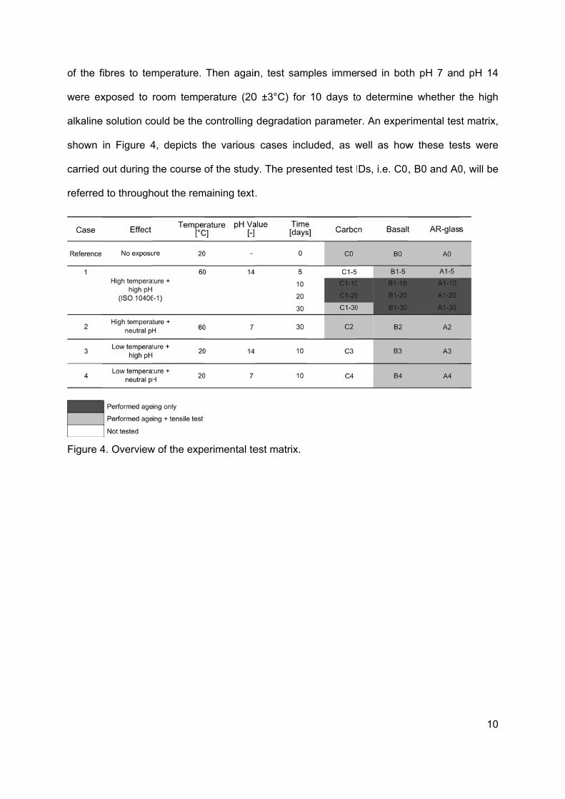
fibres to tem
xposed to r
e solution co
in Figure 4
out during t
d to through
4. Overview
mperature.
room temp
ould be the
4, depicts t
the course
hout the rem
w of the expe
Then again
erature (20
controlling
the various
of the study
maining text.
erimental te
n, test sam
0 ±3°C) for
degradatio
cases inc
y. The pres
.
est matrix.
mples imme
10 days to
n paramete
luded, as w
ented test I
rsed in bot
o determine
er. An exper
well as how
Ds, i.e. C0,
th pH 7 and
e whether
rimental tes
w these tes
, B0 and A0
10
d pH 14
the high
st matrix,
sts were
0, will be
11
4. Results
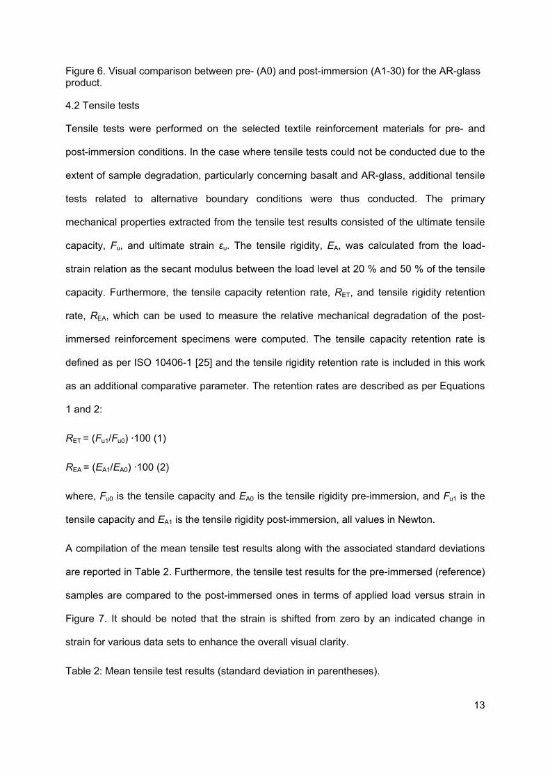
4.1 Visual observations
The visual observations noted after the alkali resistance tests are reported in this section.
The external appearance of the textile reinforcement specimens was examined pre- and
post-immersion, for comparison of colour, surface condition and change in shape.
The carbon textile reinforcement pre-immersion specimen (C0) was compared to the
associated post-immersion specimens (C1-10, C1-20, C1-30, C2). After 10-30 days of
immersion in pH 7 and pH 14 at 60°C, there was no significant visible change of colour or
surface texture and all samples were intact. According to these results, accelerated testing
using the alternative boundary conditions, so-to-say Cases 3 and 4, was not conducted.
The basalt textile reinforcement post-immersion specimens (B1-5, B1-10, B1-20, B1-30, B2,
B3, and B4) were compared to the reference pre-immersion specimens (B0). The B1-5
specimens were not marked by any major visual changes and could be tested in tension.
This product however showed signs of degradation after 10 days of immersion in the
standard conditions, which included colour change and the start of coating separation
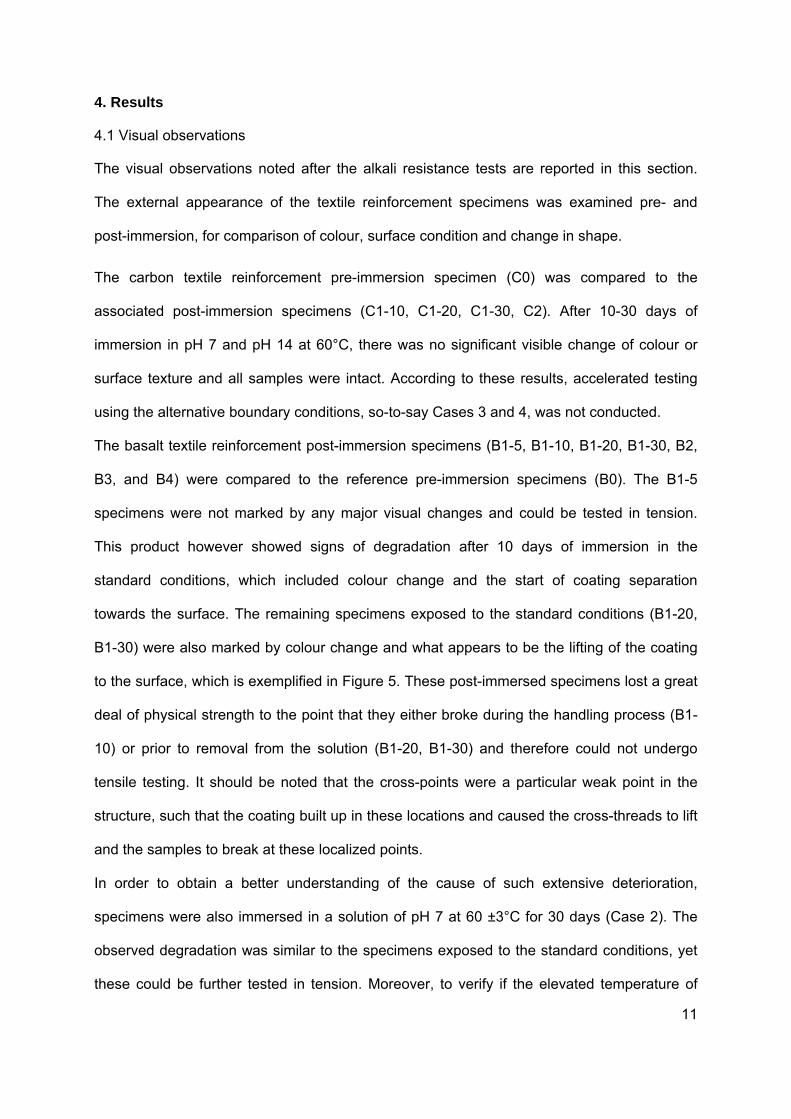
towards the surface. The remaining specimens exposed to the standard conditions (B1-20,
B1-30) were also marked by colour change and what appears to be the lifting of the coating
to the surface, which is exemplified in Figure 5. These post-immersed specimens lost a great
deal of physical strength to the point that they either broke during the handling process (B1-
10) or prior to removal from the solution (B1-20, B1-30) and therefore could not undergo
tensile testing. It should be noted that the cross-points were a particular weak point in the
structure, such that the coating built up in these locations and caused the cross-threads to lift
and the samples to break at these localized points.
In order to obtain a better understanding of the cause of such extensive deterioration,
specimens were also immersed in a solution of pH 7 at 60 ±3°C for 30 days (Case 2). The
observed degradation was similar to the specimens exposed to the standard conditions, yet
these could be further tested in tension. Moreover, to verify if the elevated temperature of
60°C wa
pH 14 f
alkalinit
minor c
broken
Figure 5product
The visu
compar
standar
cross-th
is show
could b
for the
Specim
physica
cross-th
as the gove
for 10 days
ty levels, na
olour chang
with a sligh
5. Visual cot.
ual observa
red to the
rd condition
hreads whic
wn in Figure
e easily bro
samples w
ens expose
al strength.
hreads and
erning facto
s at 20 ±3
amely B3 a
ge. The B3
ht pulling for
omparison b
ations for th
pre-immers
s (A1-5, A1
ch revealed
e 6. These s
oken by ha
which faced
ed to Case
Lastly, thos
could not b
or in this eq
°C (Cases
nd B4, had
samples ha
rce at the cr
between pre
e AR-glass
sion sample
1-10, A1-20
a thinner la
samples als
nd at the c
d the stand
3 (A3) had
se immerse
be easily tor
quation, spe
3 and 4).
d a slight bu
ad a loss of
ross-points.
e- (B0) and
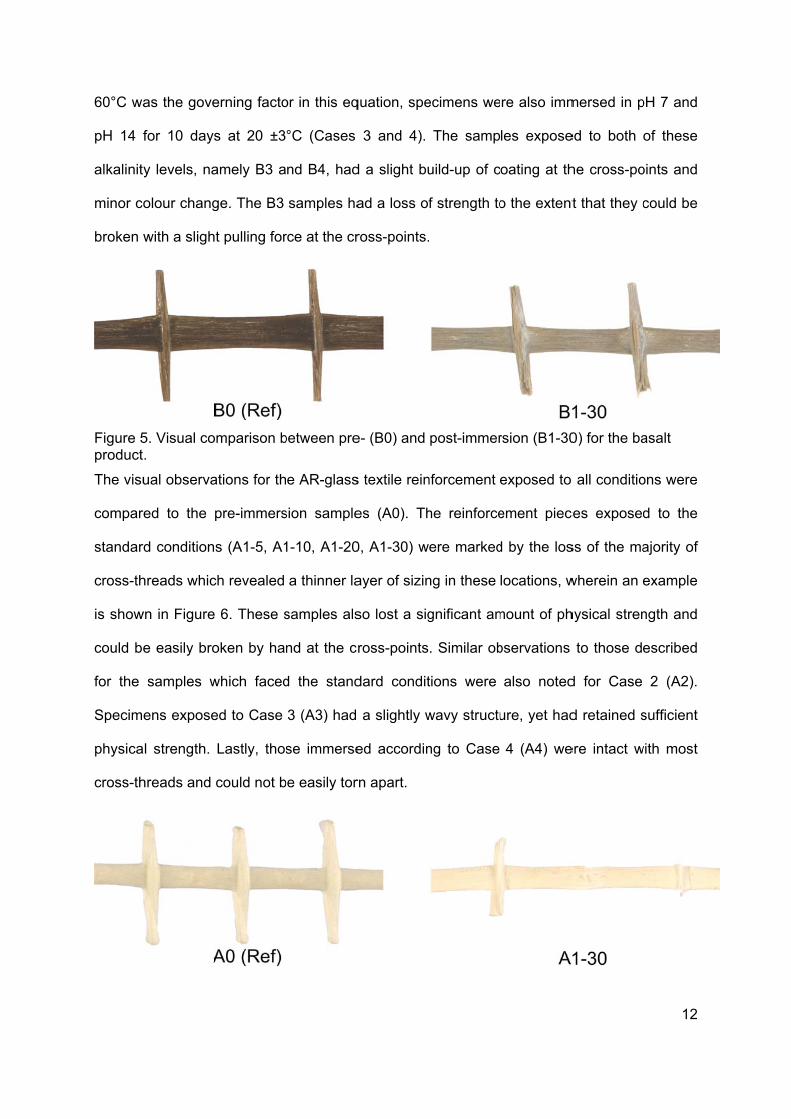
s textile rein
es (A0). Th
0, A1-30) w
ayer of sizin
so lost a sig
ross-points
dard condit
a slightly w
ed accordin
rn apart.
ecimens we
The samp
uild-up of c
f strength to
post-immer
nforcement
he reinforce
ere marked
ng in these
gnificant am
. Similar ob
tions were
wavy structu
ng to Case
re also imm
les expose
oating at th
o the extent
rsion (B1-30
exposed to
ement piec
d by the los
locations, w
mount of ph
bservations
also noted
ure, yet had
4 (A4) we
mersed in p
ed to both
he cross-po
t that they c
0) for the ba
all conditio
ces exposed
ss of the ma
wherein an e
hysical stren
to those de
d for Case
d retained s
ere intact w
12
pH 7 and
of these
oints and
could be
asalt
ons were
d to the
ajority of
example
ngth and
escribed
2 (A2).
sufficient
with most
13
Figure 6. Visual comparison between pre- (A0) and post-immersion (A1-30) for the AR-glass product.
4.2 Tensile tests
Tensile tests were performed on the selected textile reinforcement materials for pre- and
post-immersion conditions. In the case where tensile tests could not be conducted due to the
extent of sample degradation, particularly concerning basalt and AR-glass, additional tensile
tests related to alternative boundary conditions were thus conducted. The primary
mechanical properties extracted from the tensile test results consisted of the ultimate tensile
capacity, Fu, and ultimate strain εu. The tensile rigidity, EA, was calculated from the load-
strain relation as the secant modulus between the load level at 20 % and 50 % of the tensile
capacity. Furthermore, the tensile capacity retention rate, RET, and tensile rigidity retention
rate, REA, which can be used to measure the relative mechanical degradation of the post-
immersed reinforcement specimens were computed. The tensile capacity retention rate is
defined as per ISO 10406-1 [25] and the tensile rigidity retention rate is included in this work
as an additional comparative parameter. The retention rates are described as per Equations
1 and 2:
RET = (Fu1/Fu0) ·100 (1)
REA = (EA1/EA0) ·100 (2)
where, Fu0 is the tensile capacity and EA0 is the tensile rigidity pre-immersion, and Fu1 is the
tensile capacity and EA1 is the tensile rigidity post-immersion, all values in Newton.
A compilation of the mean tensile test results along with the associated standard deviations
are reported in Table 2. Furthermore, the tensile test results for the pre-immersed (reference)
samples are compared to the post-immersed ones in terms of applied load versus strain in
Figure 7. It should be noted that the strain is shifted from zero by an indicated change in
strain for various data sets to enhance the overall visual clarity.
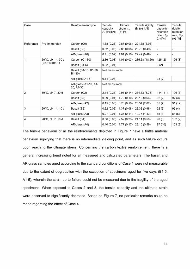
Table 2: Mean tensile test results (standard deviation in parentheses).
14
Case Reinforcement type Tensile capacity, Fu (σ) [kN]
Ultimate strain, εu (σ) [%]
Tensile rigidity, EA (σ) [kN]
Tensile capacity retention rate, RET
(σ) [%]
Tensile rigidity retention rate, REA (σ) [%]
Reference Pre-immersion Carbon (C0) 1.88 (0.23) 0.87 (0.06) 221.38 (5.05) - -
Basalt (B0) 0.62 (0.03) 2.85 (0.08) 23.73 (0.49) - -
AR-glass (A0) 0.41 (0.02) 1.91 (0.10) 22.49 (0.49) - -
1 60°C, pH 14, 30 d (ISO 10406-1)
Carbon (C1-30) 2.36 (0.03) 1.01 (0.03) 235.68 (18.60) 125 (2) 106 (8)
Basalt (B1-5) 0.02 (0.01) - - 3 (2) -
Basalt (B1-10, B1-20, B1-30)
Not measurable
AR-glass (A1-5) 0.14 (0.03) - - 33 (7) -
AR-glass (A1-10, A1-20, A1-30)
Not measurable
2 60°C, pH 7, 30 d Carbon (C2) 2.14 (0.21) 0.91 (0.14) 234.33 (6.75) 114 (11) 106 (3)
Basalt (B2) 0.39 (0.01) 1.70 (0.10) 23.13 (0.66) 62 (2) 97 (3)
AR-glass (A2) 0.15 (0.03) 0.73 (0.10) 20.54 (2.62) 35 (7) 91 (12)
3 20°C, pH 14, 10 d Basalt (B3) 0.32 (0.02) 1.37 (0.08) 23.38 (0.98) 52 (3) 99 (4)
AR-glass (A3) 0.27 (0.01) 1.37 (0.11) 19.75 (1.43) 65 (3) 88 (6)
4 20°C, pH 7, 10 d Basalt (B4) 0.56 (0.05) 2.52 (0.23) 24.11 (0.58) 90 (8) 102 (2)
AR-glass (A4) 0.40 (0.04) 1.77 (0.17) 23.15 (0.59) 97 (10) 103 (3)
The tensile behaviour of all the reinforcements depicted in Figure 7 have a brittle material
behaviour signifying that there is no intermediate yielding point, and as such failure occurs
upon reaching the ultimate stress. Concerning the carbon textile reinforcement, there is a
general increasing trend noted for all measured and calculated parameters. The basalt and
AR-glass samples aged according to the standard conditions of Case 1 were not measurable
due to the extent of degradation with the exception of specimens aged for five days (B1-5,
A1-5); wherein the strain up to failure could not be measured due to the fragility of the aged
specimens. When exposed to Cases 2 and 3, the tensile capacity and the ultimate strain
were observed to significantly decrease. Based on Figure 7, no particular remarks could be
made regarding the effect of Case 4.
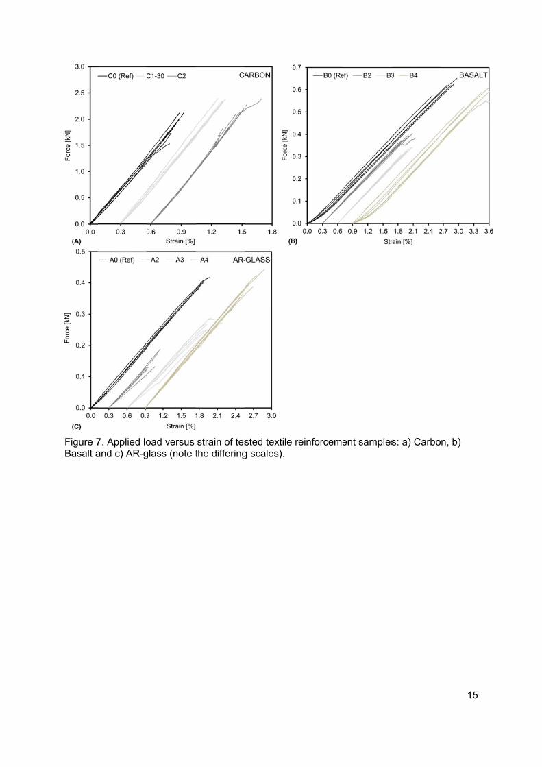
Figure 7Basalt a
7. Applied loand c) AR-g
oad versus glass (note t
strain of testhe differing
sted textile g scales).
reinforcemeent sampless: a) Carbo
15
n, b)
16
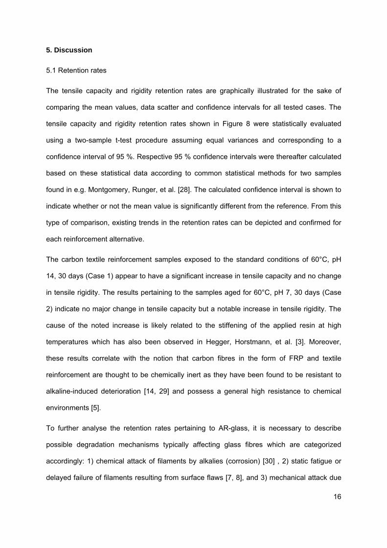
5. Discussion
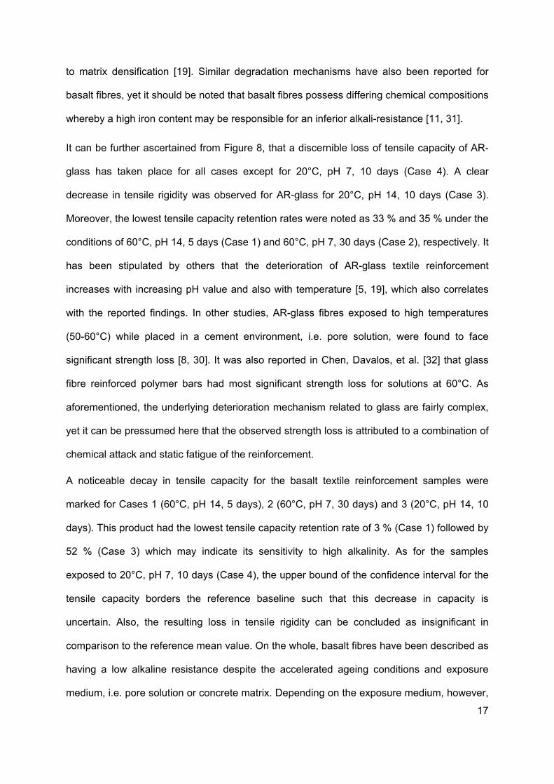
5.1 Retention rates
The tensile capacity and rigidity retention rates are graphically illustrated for the sake of
comparing the mean values, data scatter and confidence intervals for all tested cases. The
tensile capacity and rigidity retention rates shown in Figure 8 were statistically evaluated
using a two-sample t-test procedure assuming equal variances and corresponding to a
confidence interval of 95 %. Respective 95 % confidence intervals were thereafter calculated
based on these statistical data according to common statistical methods for two samples
found in e.g. Montgomery, Runger, et al. [28]. The calculated confidence interval is shown to
indicate whether or not the mean value is significantly different from the reference. From this
type of comparison, existing trends in the retention rates can be depicted and confirmed for
each reinforcement alternative.
The carbon textile reinforcement samples exposed to the standard conditions of 60°C, pH
14, 30 days (Case 1) appear to have a significant increase in tensile capacity and no change
in tensile rigidity. The results pertaining to the samples aged for 60°C, pH 7, 30 days (Case
2) indicate no major change in tensile capacity but a notable increase in tensile rigidity. The
cause of the noted increase is likely related to the stiffening of the applied resin at high
temperatures which has also been observed in Hegger, Horstmann, et al. [3]. Moreover,
these results correlate with the notion that carbon fibres in the form of FRP and textile
reinforcement are thought to be chemically inert as they have been found to be resistant to
alkaline-induced deterioration [14, 29] and possess a general high resistance to chemical
environments [5].
To further analyse the retention rates pertaining to AR-glass, it is necessary to describe
possible degradation mechanisms typically affecting glass fibres which are categorized
accordingly: 1) chemical attack of filaments by alkalies (corrosion) [30] , 2) static fatigue or
delayed failure of filaments resulting from surface flaws [7, 8], and 3) mechanical attack due
17
to matrix densification [19]. Similar degradation mechanisms have also been reported for
basalt fibres, yet it should be noted that basalt fibres possess differing chemical compositions
whereby a high iron content may be responsible for an inferior alkali-resistance [11, 31].
It can be further ascertained from Figure 8, that a discernible loss of tensile capacity of AR-
glass has taken place for all cases except for 20°C, pH 7, 10 days (Case 4). A clear
decrease in tensile rigidity was observed for AR-glass for 20°C, pH 14, 10 days (Case 3).
Moreover, the lowest tensile capacity retention rates were noted as 33 % and 35 % under the
conditions of 60°C, pH 14, 5 days (Case 1) and 60°C, pH 7, 30 days (Case 2), respectively. It
has been stipulated by others that the deterioration of AR-glass textile reinforcement
increases with increasing pH value and also with temperature [5, 19], which also correlates
with the reported findings. In other studies, AR-glass fibres exposed to high temperatures
(50-60°C) while placed in a cement environment, i.e. pore solution, were found to face
significant strength loss [8, 30]. It was also reported in Chen, Davalos, et al. [32] that glass
fibre reinforced polymer bars had most significant strength loss for solutions at 60°C. As
aforementioned, the underlying deterioration mechanism related to glass are fairly complex,
yet it can be pressumed here that the observed strength loss is attributed to a combination of
chemical attack and static fatigue of the reinforcement.
A noticeable decay in tensile capacity for the basalt textile reinforcement samples were
marked for Cases 1 (60°C, pH 14, 5 days), 2 (60°C, pH 7, 30 days) and 3 (20°C, pH 14, 10
days). This product had the lowest tensile capacity retention rate of 3 % (Case 1) followed by
52 % (Case 3) which may indicate its sensitivity to high alkalinity. As for the samples
exposed to 20°C, pH 7, 10 days (Case 4), the upper bound of the confidence interval for the
tensile capacity borders the reference baseline such that this decrease in capacity is
uncertain. Also, the resulting loss in tensile rigidity can be concluded as insignificant in
comparison to the reference mean value. On the whole, basalt fibres have been described as
having a low alkaline resistance despite the accelerated ageing conditions and exposure
medium, i.e. pore solution or concrete matrix. Depending on the exposure medium, however,

18
differing degradation mechanism have been noted, such as the formation of thick corrosion
surface layers or pitting formation [11]. Despite the use of additional surface coatings
commonly applied to AR-glass, e.g. styrene-butadiene, basalt fibres still show extensive loss
of mechanical performance due to the dissolution of the surface leading to loss of cross-
sectional area [12].
Furthermore, it is interesting to note the slight difference between the tensile capacity
retention of AR-glass (65 %) and basalt (52 %) under exposure Case 3. From these results,
it can be stipulated that both materials are being dissolved by chemical attack by alkalis
since these are fundamentally made of silicon dioxide (SiO2), thereby leading to structure
and strength loss [7, 16, 33]. As previously mentioned, certain basalt products have been
found to have a lower resistance to an alkaline environment compared to AR-glass products.
Based on these findings, however, it could solely be deduced that the particular applied
styrene-butadiene sizing could potentially be providing additional surface protection in the
case of AR-glass.
As previously mentioned, the retention rates for both basalt and AR-glass were nearly
unmeasurable for the standard conditions with the exception of those specimens tested after
5 days of ageing (Case 1). Alternatively, in such cases, the measurement of the residual yarn
or fibre diameter as demonstrated in Förster and Mäder [10] could be applied in further
studies to yield complementary results and to observe the influence of the applied sizing [11].
The analysis of the chemical degradation of the material, i.e. in terms of surface morphology,
could also be worth examining, similar to a study by Wei, Cao, et al. [16], in order to more
accurately target the source of degradation.
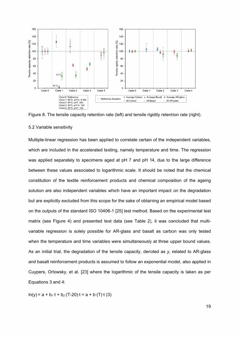
Figure 8
5.2 Vari
Multiple
which a
was ap
between
constitu
solution
but are
on the o
matrix (
variable
when th
As an in
and bas
Cuypers
Equatio
ln(y) = a
8. The tensi
iable sensit
e-linear regr
are included
plied separ
n these val
ution of the
n are also in
explicitly ex
outputs of th
(see Figure
e regression
he temperat
nitial trial, t
salt reinforc
s, Orlowsky
ons 3 and 4:
a + b1·t + b2
ile capacity
tivity
ression has
d in the acc
rately to sp
ues associ
textile rein
ndependent
xcluded from
he standard
e 4) and pr
n is solely
ture and tim
the degrada
cement prod
y, et al. [23
:
·(T-20)·t = a
retention ra
been appli
celerated tes
ecimens ag
ated to loga
nforcement
t variables
m this scop
d ISO 10406
resented te
possible fo
me variables
ation of the
ducts is ass
3] where the
a + b·(T)·t (3
ate (left) an
ied to corre
sting, name
ged at pH 7
arithmic sc
products a
which have
e for the sa
6-1 [25] tes
st data (se
or AR-glass
s were sim
tensile cap
umed to fol
e logarithm
3)
d tensile rig
elate certain
ely tempera
7 and pH 1
ale. It shou
and chemic
e an importa
ake of obtain
st method. B
ee Table 2)
s and basa
ultaneously
pacity, deno
llow an exp
ic of the te
gidity retent
n of the inde
ature and tim
4, due to t
uld be noted
cal compos
ant impact
ning an emp
Based on th
, it was co
alt as carbo
y at three up
oted as y, r
onential mo
ensile capac
ion rate (rig
ependent va
me. The reg
the large di
d that the c
sition of the
on the deg
pirical mode
he experime
oncluded th
on was onl
pper bound
related to A
odel, also a
city is taken
19
ght).
ariables,
gression
ifference
chemical
e ageing
gradation
el based
ental test
at multi-
y tested
d values.
AR-glass
pplied in
n as per
20
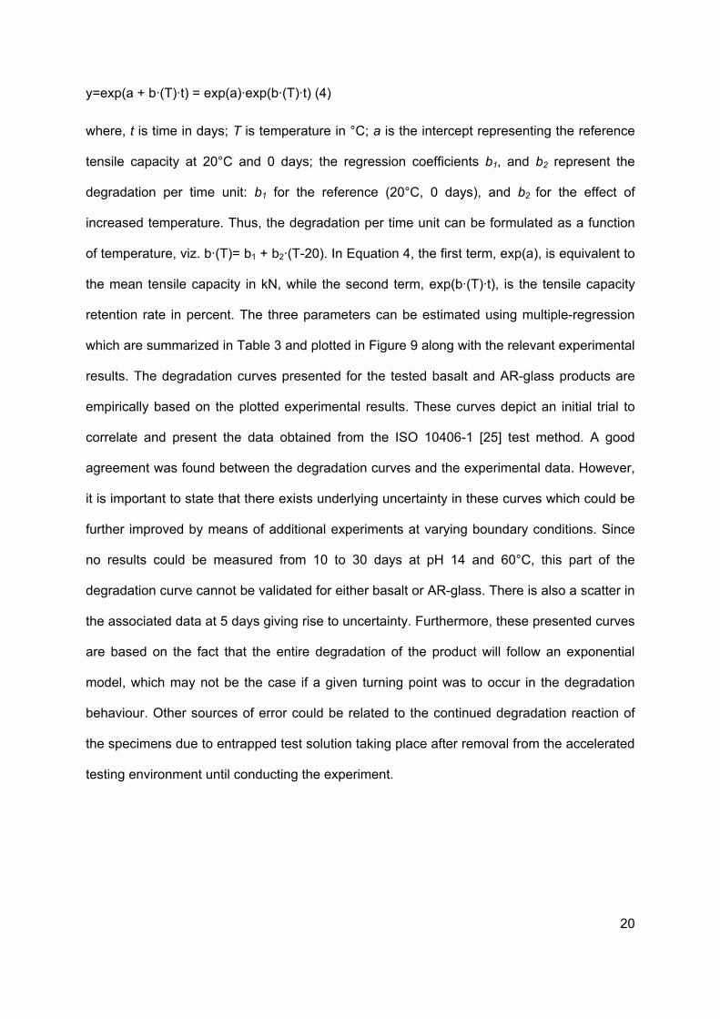
y=exp(a + b·(T)·t) = exp(a)·exp(b·(T)·t) (4)
where, t is time in days; T is temperature in °C; a is the intercept representing the reference
tensile capacity at 20°C and 0 days; the regression coefficients b1, and b2 represent the
degradation per time unit: b1 for the reference (20°C, 0 days), and b2 for the effect of
increased temperature. Thus, the degradation per time unit can be formulated as a function
of temperature, viz. b·(T)= b1 + b2·(T-20). In Equation 4, the first term, exp(a), is equivalent to
the mean tensile capacity in kN, while the second term, exp(b·(T)·t), is the tensile capacity
retention rate in percent. The three parameters can be estimated using multiple-regression
which are summarized in Table 3 and plotted in Figure 9 along with the relevant experimental
results. The degradation curves presented for the tested basalt and AR-glass products are
empirically based on the plotted experimental results. These curves depict an initial trial to
correlate and present the data obtained from the ISO 10406-1 [25] test method. A good
agreement was found between the degradation curves and the experimental data. However,
it is important to state that there exists underlying uncertainty in these curves which could be
further improved by means of additional experiments at varying boundary conditions. Since
no results could be measured from 10 to 30 days at pH 14 and 60°C, this part of the
degradation curve cannot be validated for either basalt or AR-glass. There is also a scatter in
the associated data at 5 days giving rise to uncertainty. Furthermore, these presented curves
are based on the fact that the entire degradation of the product will follow an exponential
model, which may not be the case if a given turning point was to occur in the degradation
behaviour. Other sources of error could be related to the continued degradation reaction of
the specimens due to entrapped test solution taking place after removal from the accelerated
testing environment until conducting the experiment.
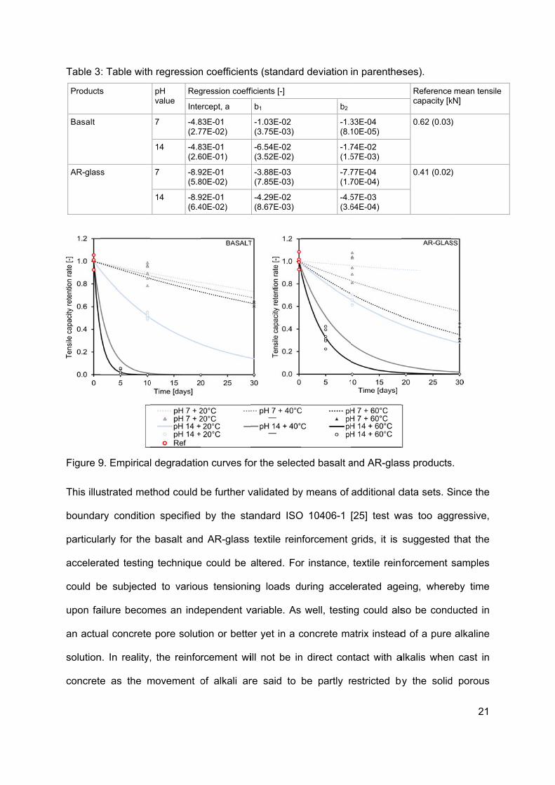
Table 3
Products
Basalt
AR-glas
Figure 9
This illu
bounda
particula
accelera
could b
upon fa
an actu
solution
concrete
: Table with
s
s
9. Empirical
ustrated met
ry condition
arly for the
ated testing
be subjecte
ailure becom
al concrete
n. In reality,
e as the m
h regression
pH value
Reg
Inte
7 -4.8(2.7
14 -4.8(2.6
7 -8.9(5.8
14 -8.9(6.4
l degradatio
thod could
n specified
basalt and
g technique
d to variou
mes an inde
e pore solut
, the reinfo
movement o
n coefficient
gression coeff
ercept, a
83E-01 77E-02)
83E-01 60E-01)
92E-01 80E-02)
92E-01 40E-02)
on curves fo
be further v
by the sta
d AR-glass
e could be a
us tensionin
ependent v
ion or bette
rcement wi
of alkali ar
ts (standard
ficients [-]
b1
-1.03E-02 (3.75E-03)
-6.54E-02 (3.52E-02)
-3.88E-03 (7.85E-03)
-4.29E-02 (8.67E-03)
or the selec
validated by
andard ISO
textile rein
altered. Fo
ng loads d
variable. As
er yet in a c
ill not be in
re said to
d deviation
b2
-1.3(8.1
-1.7(1.5
-7.7(1.7
-4.5(3.6
ted basalt a
y means of
O 10406-1
nforcement
r instance,
uring acce
well, testin
concrete ma
n direct con
be partly r
in parenthe
33E-04 10E-05)
74E-02 57E-03)
77E-04 70E-04)
57E-03 64E-04)
and AR-glas
additional d
[25] test w
grids, it is
textile reinf
lerated age
ng could als
atrix instead
ntact with a
restricted by
eses).
Referencecapacity [k
0.62 (0.03)
0.41 (0.02)
ss products
data sets. S
was too agg
suggested
forcement
eing, where
so be cond
d of a pure
alkalis when
by the solid
21
mean tensile kN]
)
)
s.
Since the
gressive,
that the
samples
eby time
ducted in
alkaline
n cast in
d porous
22
material [10]. Alternatively, given a façade panel application, the reinforcement will likely not
be found in a constant state of wetness during service life such that wetting and drying cycles
could be a more appropriate testing method [6]. The findings obtained from this experimental
study could be used to predict the strength retention as a function of real time while reflecting
the actual environmental conditions of the intended use according to a similar approach
proposed by Dejke [10]. A larger data set corresponding to the same test solution, e.g. pH
14, is however required to enable a correlation in terms of a time shift factor, TSF (see [10]).
6. Conclusions
The tensile behaviour of selected textile reinforcement products was investigated under
accelerated ageing conditions as per ISO 10406-1 [25]. It was observed that the tested
carbon textile reinforcement has a superior alkali and temperature resistance, while the
standard conditions were found to be too aggressive for the tested basalt and AR-glass
products causing them to have nearly unmeasurable capacity after ageing. Testing the
reinforcement grids according to alternative accelerated ageing schemes yielded significant
trends, whereby the AR-glass product was found to be temperature sensitive particularly at
60°C and could retain more tensile strength (65%) than basalt (52%) while being exposed to
20°C, pH 14, 10 days. It is thought that the type and amount of applied sizing has a
significant impact on these observed results. Empirical exponential models of the
degradation of the tensile retention rate were developed as a function of temperature and
time for the basalt and AR-glass products; the models were calibrated through linear
regression. The models had an overall good correlation with the experimental data, yet could
be further verified by means of additional experiments. Furthermore, the carbon
reinforcement grid’s tensile capacity and rigidity were generally maintained under all tested
conditions, thus signifying favourable durability properties. Despite it having the highest initial
cost, it is thought that its enhanced durability could provide a long-term payback. It is
important to note that the conclusions reached in this study cannot be directly applied to

23
other textile reinforcement materials or fibres as each material differs in terms of chemical
composition, fabrication and applied sizing. The main drawback of this applied test method is
the fact that the simulated pore solution may have overestimated or inadequately
represented realistic boundary conditions of textile reinforcement in a concrete matrix.
This work also included the development of methods which could be used to support those
pertaining to tensile tests in the ISO 10406-1 [25] standard such as the preparation and
selection of end anchorage, as well as a method to measure the strain up to failure. In further
studies, it could be worth investigating a larger experimental sample size, alternative
temperature and time ranges, wetting/drying cycles, test solutions and degradation of
materials subject to tensioning load during ageing. It could also be valuable to analyse the
chemical degradation processes affecting the surface structure of the reinforcement. Overall,
there remains a need for an accelerated ageing test method tailored to TRC, as well as a
database or model that can predict the residual tensile strength (and/or long term
performance) of various textile reinforcement products according to real-time degradation
due to varying mechanical and environmental load conditions.
Acknowledgments
The presented research was made possible with the support of the European Community’s
Seventh Framework Programme under grant agreement 608893 (H-House) and FORMAS
IQS (Tekocrete II – Energy efficient thin façade elements for retrofitting of Million Programme
housing: TRC textile reinforced concrete façade elements). More information about the H-
house research project can be found at www.h-house-project.eu.com.
References
[1] Mobasher B. Mechanics of fiber and textile reinforced cement composites: CRC press; 2012.
[2] Shams A, Horstmann M, Hegger J. Experimental investigations on Textile-Reinforced Concrete (TRC) sandwich sections. Composite Structures. 2014;118:643-53.
[3] Hegger J, Horstmann M, Feldmann M, Pyschny D, Raupach M, Büttner T, et al. Sandwich Panels Made of TRC and Discrete and Continuous Connectors. In: Brameshuber W, editor. International RILEM Conference on Material Science - 2nd ICTRC - Textile Reinforced Concrete - Theme 1. Aachen RILEM Publications SARL; 2010. p. 381-92.
24
[4] Mumenya S, Tait R, Alexander M. Mechanical behaviour of Textile Concrete under accelerated ageing conditions. Cement and Concrete Composites. 2010;32(8):580-8.
[5] Mechtcherine V. Towards a durability framework for structural elements and structures made of or strengthened with high-performance fibre-reinforced composites. Construction and Building Materials. 2012;31:94-104.
[6] Bentur A, Mindess S. Fibre reinforced cementitious composites: CRC Press; 2006.
[7] Purnell P, Short NR, Page CL. A static fatigue model for the durability of glass fibre reinforced cement. Journal of Materials Science. 2001;36(22):5385-90.
[8] Orlowsky J, Raupach M, Cuypers H, Wastiels J. Durability modelling of glass fibre reinforcement in cementitious environment. Mater Struct. 2005;38(2):155-62.
[9] Ortlepp S, Jesse F. Experimental investigation of static fatigue strength of textile reinforced concrete. 1st International RILEM Conference on Textile Reinforced Concrete (ICTRC): RILEM Publications SARL; 2006. p. 131-40.
[10] Dejke V. Durability of FRP reinforcement in concrete: literature review and experiments. Gothenburg: Chalmers University of Technology; 2001.
[11] Scheffler C, Förster T, Mäder E, Heinrich G, Hempel S, Mechtcherine V. Aging of alkali-resistant glass and basalt fibers in alkaline solutions: Evaluation of the failure stress by Weibull distribution function. Journal of Non-Crystalline Solids. 2009;355(52):2588-95.
[12] Hempel S, Butler M, Mechtcherine V. Bond Behaviour and Durability of Basalt Fibres in Cementitious Matrices. In: Brameshuber W, editor. 3rd ICTR International Conference on Textile Reinforced Concrete Aachen, Germany: RILEM SARL; 2015. p. 225-33.
[13] Butler M, Mechtcherine V, Hempel S. Experimental investigations on the durability of fibre–matrix interfaces in textile-reinforced concrete. Cement and Concrete Composites. 2009;31(4):221-31.
[14] Micelli F, Nanni A. Durability of FRP rods for concrete structures. Construction and Building Materials. 2004;18(7):491-503.
[15] Cuypers H, Orlowsky J, Raupach M, Büttner T. Durability aspects of AR-glass-reinforcement in textile reinforced concrete, Part 1: Material behaviour. In: Grosse CU, editor. Advances in Construction Materials 2007: Springer Berlin Heidelberg; 2007. p. 381-8.
[16] Wei B, Cao H, Song S. Tensile behavior contrast of basalt and glass fibers after chemical treatment. Materials & Design. 2010;31(9):4244-50.
[17] Förster T, Plonka R, Scheffler C, Mäder E. Challenges for Fibre and Interphase Design of Basalt Fibre Reinforced Concrete. International RILEM Conference on Material Science: RILEM Publications SARL; 2010. p. 57-66.
[18] Förster T, Mäder E. Performance of Modified Basalt Fibres. Proceedings of the 18th International Conference on Composite Materials (ICCM18), Korean Society for Composite Materials2011.
[19] Butler M, Mechtcherine V, Hempel S. Durability of textile reinforced concrete made with AR glass fibre: effect of the matrix composition. Mater Struct. 2010;43(10):1351-68.
[20] Scheffler C, Gao S, Plonka R, Mäder E, Hempel S, Butler M, et al. Interphase modification of alkali-resistant glass fibres and carbon fibres for textile reinforced concrete II: Water adsorption and composite interphases. Composites Science and Technology. 2009;69(7):905-12.
[21] Büttner T, Orlowsky J, Raupach M, Hojczyk M, Weichold O, Brameshuber W. Enhancement of the Durability of Alkali-resistant Glass-Rovings in concrete. International RILEM Conference on Material Science. Germany: RILEM Publications SARL; 2010. p. 333-42.
[22] Orlowsky J, Raupach M. Durability model for AR-glass fibres in textile reinforced concrete. Mater Struct. 2008;41(7):1225-33.
[23] Cuypers H, Orlowsky J, Raupach M, Büttner T, Wastiels J. Durability aspects of AR-glass-reinforcement in textile reinforced concrete, Part 2: Modelling and exposure to outdoor weathering. In: Grosse CU, editor. Advances in Construction Materials 2007: Springer Berlin Heidelberg; 2007. p. 389-95.
25
[24] Hegger J, Kulas C, Schneider H, Brameshuber W, Hinzen M, Raupach M, et al. TRC Pedestrian Bridge-Design, Load-bearing Behavior and Production Processes of a Slender and Light-weight Construction. In: Brameshuber W, editor. International RILEM Conference on Material Science - 2nd ICTRC - Textile Reinforced Concrete - Theme 1. Aachen: RILEM Publications SARL; 2010. p. 353-64.
[25] ISO 10406-1. Fibre-reinforced polymer (FRP) reinforcement of concrete - Test Methods. Part 1: FRP bars and grids. Switzerland: International Organization for Standardization; 2008.
[26] Van de Velde K, Kiekens P, Van Langenhove L. Basalt fibres as reinforcement for composites. Proceedings of 10th international conference on composites/nano engineering, University of New Orleans, New Orleans, LA, USA2003. p. 20-6.
[27] Castro PF, Carino NJ. Tensile and nondestructive testing of FRP bars. Journal of composites for construction. 1998;2(1):17-27.
[28] Montgomery DC, Runger GC, Hubele NF. Engineering statistics. 5th ed: John Wiley & Sons; 2011.
[29] Scheffler C, Gao S, Plonka R, Mäder E, Hempel S, Butler M, et al. Interphase modification of alkali-resistant glass fibres and carbon fibres for textile reinforced concrete I: Fibre properties and durability. Composites Science and Technology. 2009;69(3):531-8.
[30] Majumdar AJ, West JM, Larner L. Properties of glass fibres in cement environment. Journal of Materials Science. 1977;12(5):927-36.
[31] Scheffler C, Förster T, Mäder E. Beschleunigte Alterung von Glasfasern in alkalischen Lösungen: Einflüsse auf die mechanischen Eigenschaften (Accelerated aging of glass fibers in alkali solutions: Influence on the mechanical properties). In: Curbach M, Jesse F, editors. 4th Colloquium on Textile Reinforced Structures (CTRS4). Dresden, Germany2009. p. 63-74.
[32] Chen Y, Davalos JF, Ray I, Kim H-Y. Accelerated aging tests for evaluations of durability performance of FRP reinforcing bars for concrete structures. Composite Structures. 2007;78(1):101-11.
[33] Militký J, Zeisbergerová J, Kovačič V. Chemical degradation of basalt fibers. http://centrum.tul.cz/centrum/centrum/3Aplikace/3.2_publikace/[3.2.13].pdf: Technical University of Liberec; 2009.