Embed Size (px)
Citation preview
INTERNATIONAL ORGANISATION FOR STANDARDISATION
INTERNATIONAL ELECTROTECHNICAL COMMISSION
Information technology –
Information Technology: Scalable Compression and Coding of Continuous-Tone Still Images
ISO/IEC 19566-1 JPEG Systems Part1: Packaging of Information using Codestreams and File Formats
Draft ITU-T Recommendation | International Standard
CONTENTSPage
Foreword...................................................................................................................................................................3Introduction...............................................................................................................................................................31 Scope..............................................................................................................................................................42 Normative references.....................................................................................................................................4
2.1 Additional references..........................................................................................................................53 Definitions, Abbreviations and Symbols.......................................................................................................5
3.1 Definitions..........................................................................................................................................53.2 Symbols..............................................................................................................................................63.3 Abbreviations.....................................................................................................................................7
4 Conventions...................................................................................................................................................74.1 Conformance language.......................................................................................................................74.2 Operators............................................................................................................................................7
4.2.1 Arithmetic operators.........................................................................................................74.2.2 Logical operators..............................................................................................................84.2.3 Relational operators..........................................................................................................84.2.4 Precedence order of operators..........................................................................................84.2.5 Mathematical functions....................................................................................................8
5 General...........................................................................................................................................................96 Background....................................................................................................................................................9
6.1 Organization of Information.............................................................................................................11Annex A: Organization of Information Signaling, Packaging and Storage...........................................................12
A.1 Introduction......................................................................................................................................12A.2 Storage Layers..................................................................................................................................12A.3 Interface Aspects..............................................................................................................................12A.3 Interoperability.................................................................................................................................13A.2 Syntax Elements for Information Signaling, Transport and Storage...............................................13
Annex B: Concept of Boxes...................................................................................................................................14B.1 Introduction......................................................................................................................................14B.2 Box definition...................................................................................................................................14B.3 Derivation of New Box Based File Formats....................................................................................15B.4 Carriage mechanisms for box structures within codestreams..........................................................15B.5 Boxes in use......................................................................................................................................16
B.5.1 JPEG 2000 family..........................................................................................................16B.5.1 JPEG-XT Family Standards...........................................................................................30B.5.1 JPEG Search...................................................................................................................34B.5.1 JPEG...............................................................................................................................34
B.6 Placement of Boxes...............................................................................................................................34Annex C: Box-Based File Format Structure...........................................................................................................36
C.1 Introduction..................................................................................................................................36C.2 Boxed-base file format syntax..............................................................................................36C.3 Overview about existing file formats.................................................................................36C.4 Example File Format Structure (Informative only)........................................................36
Annex D: Codestream Syntax.................................................................................................................................38D.1 Introduction......................................................................................................................................38D.2 Markers, marker segments, and headers...........................................................................................38
D.2.1 Types of markers and marker segments.........................................................................38D.2.2 Marker Ranges...............................................................................................................38D.2.3 Marker and marker segment and codestream rules........................................................39D.2.4 Bit-stuffing and byte-stuffing in content........................................................................39
1
D.2.5 Graphical descriptions of markers (informative)...........................................................39D.3 Markers in use.......................................................................................................................................41
D.3.1 ISO/IEC 15444-x family........................................................................................................41D.3.2 ISO/IEC 10918 and 18777 family..........................................................................................42
Annex E: Codec/Codestream Functionality Guidelines.........................................................................................43E.1 Introduction......................................................................................................................................43E.2 Resolution Scalability.......................................................................................................................43E.3 Bit Depth Scalability........................................................................................................................43E.4 Spatial Scalability.............................................................................................................................44E.5 Component Scalability.....................................................................................................................44
2 ITU-T Rec. T.xxxx (200x E)

ForewordISO (the International Organization for Standardization) and IEC (the International Electrotechnical Commission) form the specialized system for worldwide standardization. National bodies that are members of ISO or IEC participate in the development of International Standards through technical committees established by the respective organization to deal with particular fields of technical activity. ISO and IEC technical committees collaborate in fields of mutual interest. Other international organizations, governmental and non-governmental, in liaison with ISO and IEC, also take part in the work. In the field of information technology, ISO and IEC have established a joint technical committee, ISO/IEC JTC 1.
International Standards are drafted in accordance with the rules given in the ISO/IEC Directives, Part 2.
The main task of the joint technical committee is to prepare International Standards. Draft International Standards adopted by the joint technical committee are circulated to national bodies for voting. Publication as an International Standard requires approval by at least 75 % of the national bodies casting a vote.
In exceptional circumstances, the joint technical committee may propose the publication of a Technical Report of one of the following types:
— type 1, when the required support cannot be obtained for the publication of an International Standard, despite repeated efforts;
— type 2, when the subject is still under technical development or where for any other reason there is the future but not immediate possibility of an agreement on an International Standard;
— type 3, when the joint technical committee has collected data of a different kind from that which is normally published as an International Standard (“state of the art”, for example).
Technical Reports of types 1 and 2 are subject to review within three years of publication, to decide whether they can be transformed into International Standards. Technical Reports of type 3 do not necessarily have to be reviewed until the data they provide are considered to be no longer valid or useful.
Attention is drawn to the possibility that some of the elements of this document may be the subject of patent rights. ISO and IEC shall not be held responsible for identifying any or all such patent rights.
ISO/IEC TR 19566-1, which is a Technical Report of type 3, was prepared by Joint Technical Committee ISO/IEC JTC 1, Information technology, Subcommittee SC 29, Coding of audio, picture, multimedia and hypermedia information.
IntroductionThis Recommendation | International standard specifies a system layer for future standards of ISO/IEC JTC1 SC29 WG1 based on the experience of already existing standards.
With the development of coding technologies, WG1 has defined a huge amount of different file formats and multiple variants of codestream syntax. Many of them are specialized to some dedicated use cases or compression algorithms. Consequently, it is difficult to maintain the overview about existing file formats, their capabilities and their architecture. In particular, establishment of a Systems framework handling all the different coding technologies and WG tools in a harmonized and unified manner is almost impossible.
This document hence aims to describe common architectural concepts for file formats and codestream formats. By these means, it lays out guidelines for future file formats and codestream syntax. By obeying these guidelines, future standards ensure to fit into an overall operable Systems infrastructure that can handle all tools standardized by the WG1 body.
3
INTERNATIONAL STANDARDISO/IEC 29199-2 : 200x (E)ITU-T Rec. T.xxxx (200x E)
ITU-T RECOMMENDATION
INFORMATION TECHNOLOGY – INFORMATION TECHNOLOGY – JPEG SYSTEMS PART1:
PACKAGING OF INFORMATION USING CODESTREAMS AND FILE FORMATS
1 ScopeThis Recommendation | International standard specifies a system layer for JPEG standards, referred to as JPEG Systems.
This document describes the common architecture of file formats and codestream formats as they are assumed by the WG1 ecosystem of tools and transport mechanisms standardized in the Systems group. All future Systems components shall support codestreams and file formats obeying these guidelines.
2 Normative referencesThe following Recommendations and International Standards contain provisions which, through reference in this text, constitute provisions of this Recommendation | International Standard. At the time of publication, the editions indicated were valid. All Recommendations and Standards are subject to revision, and parties to agreements based on this Recommendation | International Standard are encouraged to investigate the possibility of applying the most recent edition of the Recommendations and Standards listed below. Members of IEC and ISO maintain registers of currently valid International Standards. The Telecommunication Standardization Bureau of the ITU maintains a list of currently valid ITU-T Recommendations.ITU-T Rec. T.800 | ISO/IEC 15444-1: Information technology – JPEG 2000 Image Coding System – Part 1: Core coding system
ITU-T Rec. T.801 | ISO/IEC 15444-2: Information technology - JPEG 2000 image coding system - Part 2: Extensions
ITU-T Rec. T.802 | ISO/IEC 15444-3 : Information technology - JPEG 2000 image coding system - Part 3: Motion JPEG 2000
ISO/IEC 14496-12, ISO/IEC 15444-12: Information technology - JPEG 2000 image coding system - Part 12: ISO base media file format
ISO/IEC 15444-6:2013: Information technology -- JPEG 2000 image coding system -- Part 6: Compound image file format
ISO/IEC 15444-9:2005: Information technology -- JPEG 2000 image coding system- Part 9: Interactivity tools, APIs and protocols
ISO/IEC 18477-3: Information Technology - Scalable Compression and Coding of Continuous-Tone Still Images: Box File FormatITU-T Rec. T.81 | ISO/IEC 10918-1: Information Technology – Digital Compression and Coding of Continuous Tone Still Images – Requirements and Guidelines ITU-T T.84 | ISO/IEC 10918-3: Information technology -- Digital compression and coding of continuous-tone still images: ExtensionsITU-T T.87 | ISO/IEC 14495-1: Information technology -- Lossless and near-lossless compression of continuous-tone still images: BaselineITU-T Rec. T.871 | ISO/IEC 10918-5: Information technology -- Digital compression and coding of continuous-tone still images: JPEG File Interchange Format
ISO/IEC 646:1991: Information technology -- ISO 7-bit coded character set for information interchange
4 ITU-T Rec. T.xxxx (200x E)
2.1 Additional references
3 Definitions, Abbreviations and Symbols
3.1 DefinitionsFor the purposes of this Recommendation | International Standard, the following definitions apply.
backward compatibility: A standard is backward compatible when the new specification includes the old one. This means that any devices implementing the new standard can also interpret all data compliant with the old version of the standard. An old device, however, only compliant with the old version of the standard might not be able to interpret the data compliant with the new version of the standard.
bit stream: Partially encoded or decoded sequence of bits comprising an entropy-coded segment.
box: a structured collection of data describing the image or the image decoding process. See Annex B.2 for the definition of boxes.
byte: A group of 8 bits.
coder: An embodiment of a coding process.
coding: Encoding or decoding.
coding model: A procedure used to convert input data into symbols to be coded.
(coding) process: A general term for referring to an encoding process, a decoding process, or both.
compression: Reduction in the number of bits used to represent source image data.
component: A two-dimensional array of samples having the same designation in the output or display device. An image typically consists of several components, e.g. red, green and blue.
continuous-tone image: An image whose components have more than one bit per sample.
decoder: An embodiment of a decoding process.
decoding process: A process which takes as its input compressed image data and outputs a continuous-tone image.
dequantization: The inverse procedure to quantization by which the decoder recovers a representation of the DCT coefficients.
downsampling: A procedure by which the spatial resolution of a component is reduced.
encoder: An embodiment of an encoding process.
encoding process: A process which takes as its input a continuous-tone image and outputs compressed image data.
entropy-coded (data) segment: An independently decodable sequence of entropy encoded bytes of compressed image data.
entropy decoder: An embodiment of an entropy decoding procedure.
entropy decoding: A lossless procedure which recovers the sequence of symbols from the sequence of bits produced by the entropy encoder.
entropy encoder: An embodiment of an entropy encoding procedure.
entropy encoding: A lossless procedure which converts a sequence of input symbols into a sequence of bits such that the average number of bits per symbol approaches the entropy of the input symbols.
forward compatibility: If a new standard is forward compatible, than devices only compliant with the old version of the standard are nevertheless able to interpret the data conforming with the new standard. However, it might be possible that the obtained results are not as good as when using a device compliant with the new version of the standard
grayscale image: A continuous-tone image that has only one component.
high dynamic range: An image or image data comprised of more than eight bits per sample, coded in floating point representation.
Intermediate dynamic range: An image or image data comprised of more than eight bits per sample, coded in integer representation.
Joint Photographic Experts Group; JPEG: The informal name of the committee which created this Specification. The “joint” comes from the ITU-T and ISO/IEC collaboration.
legacy decoder: An embodiment of a decoding process conforming to ITU.T Rec.T.81|ISO/IEC 10918-1, confined to the lossy DCT process and the baseline, sequential or progressive modes, decoding at most four components to eight bits per component.
lossless: A descriptive term for encoding and decoding processes and procedures in which the output of the decoding procedure(s) is identical to the input to the encoding procedure(s).
5
lossless coding: The mode of operation which refers to any one of the coding processes defined in this Specification in which all of the procedures are lossless.
lossy: A descriptive term for encoding and decoding processes which are not lossless.
low-dynamic range: An image or image data comprised of data with no more than eight bits per sample.
marker: A two-byte code in which the first byte is hexadecimal FF and the second byte is a value between 1 and hexadecimal FE.
marker segment: A marker together with its associated set of parameters.
metadata: Additional data associated with the image data beyond the image data.minimum coded unit; MCU: The smallest group of data units that is coded.
pixel: A collection of sample values in the spatial image domain having all the same sample coordinates, e.g. a pixel may consist of three samples describing its red, green and blue value.
point transform: Scaling of a sample or DCT coefficient by a factor.
precision: Number of bits allocated to a particular sample or DCT coefficient.
procedure: A set of steps which accomplishes one of the tasks which comprise an encoding or decoding process.
quantization value: An integer value used in the quantization procedure.
quantize: The act of performing the quantization procedure for a DCT coefficient.
residual scan: An additional pass over the image data invisible to legacy decoders which provides additive and/or multiplicative correction data of the legacy scans to allow reproduction of high-dynamic range or wide color gamut data.
refinement scan: An additional pass over the image data invisible to legacy decoders which provides additional least significant bits to extend the precision of the DCT transformed coefficients.
sample: One element in the two-dimensional image array which comprises a component.
sample grid: A common coordinate system for all samples of an image. The samples at the top left edge of the image have the coordinates (0,0), the first coordinate increases towards the right, the second towards the bottom.
scan: A single pass through the data for one or more of the components in an image.
scan header: A marker segment that contains a start-of-scan marker and associated scan parameters that are coded at the beginning of a scan.
table specification data: The coded representation from which the tables used in the encoder and decoder are generated and their destinations specified.
(uniform) quantization: The procedure by which DCT coefficients are linearly scaled in order to achieve compression.
upsampling: A procedure by which the spatial resolution of a component is increased.
vertical sampling factor: The relative number of vertical data units of a particular component with respect to the number of vertical data units in the other components in the frame.
zero byte: The 0x00 byte.
3.2 Symbols
X Width of the sample grid in positionsY Height of the sample grid in positionsNf Number of components in an imagesi,x Subsampling factor of component i in horizontal directionsi,y Subsampling factor of component i in vertical directionHi Subsampling indicator of component i in the frame headerVi Subsampling indicator of component i in the frame headervx,y Sample value at the sample grid position x,yh Additional number of DCT coefficients bits represented by refinement scans, 8+h is the number of non-
fractional bits (i.e. bits in front of the "binary dot") of the output of the inverse DCT process.Rb Additional bits in the HDR image. 8+Rb is the sample precision of the reconstructed HDR image.
6 ITU-T Rec. T.xxxx (200x E)
3.3 AbbreviationsFor the purposes of this Recommendation | International Standard, the following abbreviations apply.
ASCII American Standard Code for Information Interchange LSB Least Significant BitMSB Most Significant BitHDR High Dynamic RangeIDR Intermediate Dynamic RangeLDR Low Dynamic RangeTMO Tone Mapping OperatorDCT Discrete Cosine Transformation
4 Conventions
4.1 Conformance languageThis Recommendation | International Standard consists of normative and informative text.
Normative text is that text which expresses mandatory requirements. The word "shall" is used to express mandatory requirements strictly to be followed in order to conform to this Specification and from which no deviation is permitted. A conforming implementation is one that fulfils all mandatory requirements.
Informative text is text that is potentially helpful to the user, but not indispensable and can be removed, changed or added editorially without affecting interoperability. All text in this Recommendation | International Standard is normative, with the following exceptions: the Introduction, any parts of the text that are explicitly labelled as "informative", and statements appearing with the preamble "NOTE" and behaviour described using the word "should". The word "should" is used to describe behaviour that is encouraged but is not required for conformance to this Specification.
The keywords "may" and "need not" indicate a course of action that is permissible in a conforming implementation.
The keyword "reserved" indicates a provision that is not specified at this time, shall not be used, and may be specified in the future. The keyword "forbidden" indicates "reserved" and in addition indicates that the provision will never be specified in the future.
4.2 OperatorsNOTE – Many of the operators used in this Recommendation | International Standard are similar to those used in the C programming language.
4.2.1 Arithmetic operators+ Addition Subtraction (as a binary operator) or negation (as a unary prefix operator)
* Multiplication
/ Division without truncation or rounding.
smod x smod a is the unique value y between -(a-1)/2 and (a-1)/2
for which y+Na = x with a suitable integer N.
umod x mod a is the unique value y between 0 and a-1
for which y+Na = y with a suitable integer N.
7
4.2.2 Logical operators|| Logical OR
&& Logical AND
! Logical NOT x {A, B} is defined as (x == A || x == B) x {A, B} is defined as (x != A && x != B)
4.2.3 Relational operators> Greater than
>= Greater than or equal to
< Less than
<= Less than or equal to
== Equal to
!= Not equal to
4.2.4 Precedence order of operatorsOperators are listed below in descending order of precedence. If several operators appear in the same line, they have equal precedence. When several operators of equal precedence appear at the same level in an expression, evaluation proceeds according to the associativity of the operator either from right to left or from left to right.
Operators Type of operation Associativity
(), [ ], . Expression Left to Right Unary negation
*, / Multiplication Left to Right
umod, smod Modulo (remainder) Left to Right
+, Addition and Subtraction Left to Right
< , >, <=, >= Relational Left to Right
4.2.5 Mathematical functionsx Ceil of x. Returns the smallest integer that is greater than or equal to x.
x Floor of x. Returns the largest integer that is lesser than or equal to x.
|x| Absolute value, is –x for x < 0, otherwise x.
sign(x) Sign of x, zero if x is zero, +1 if x is positive, -1 if x is negative.
clamp(x,min,max) Clamps x to the range [min,max]: returns min if x < min, max if x > max or otherwise x.
power(x,a) Raises the value of x to the power of a. x is a non-negative real number, a is a real number. Power(x,a) is equal to exp(a×log(x)) where exp is the exponential function and log() the natural logarithm. If x is zero and a is positive, power(x,a) is defined to be zero.
8 ITU-T Rec. T.xxxx (200x E)
5 General
The purpose of this clause is to give an informative overview of the elements specified in this Specification. Another purpose is to introduce many of the terms which are defined in clause 3. These terms are printed in italics upon first usage in this clause.
There are three elements specified in this Specification:
a) An encoder is an embodiment of an encoding process. An encoder takes as input digital source image data and encoder specifications, and by means of a specified set of procedures generates as output a codestream.
b) A decoder is an embodiment of a decoding process. A decoder takes as input a codestream, and by means of a specified set of procedures generates as output digital reconstructed image data.
c) The codestream is a compressed image data representation which includes all necessary data to allow a (full or approximate) reconstruction of the sample values of a digital image. Additional data might be required that define the interpretation of the sample data, such as color space or the spatial dimensions of the samples.
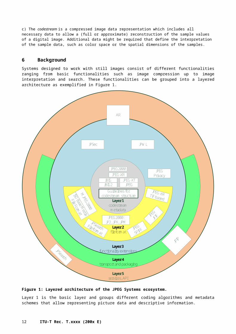
6 BackgroundSystems designed to work with still images consist of different functionalities ranging from basic functionalities such as image compression up to image interpretation and search. These functionalities can be grouped into a layered architecture as exemplified in Figure 1.
9
Layer 5services, API
Layer 4transport and packaging
Layer 3functionality extensions
Layer 2fileformat
Layer 1codestreammetadata
JPEG2000JPEG-XR
JPEGJPEG-XTJBIG
JBIG2
JPEG2000:JP2, JPX, JPM
JPEG
JFIF
JPSearchFileformat
Guidelines for codestream structureISO Base M
edia
File Format
MJPEG2000
JPSec
JPEG-XRTIF based
JPWL
JPEGPrivacy
JPEG
SPIFF
JPIP
JPSearch
AR
Figure 1: Layered architecture of the JPEG Systems ecosystem.
Layer 1 is the basic layer and groups different coding algorithms and metadata schemes that allow representing picture data and descriptive information.
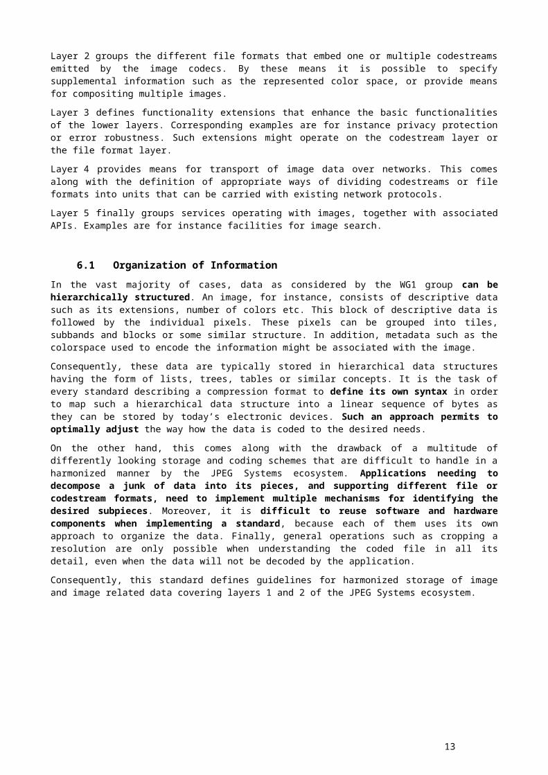
Layer 2 groups the different file formats that embed one or multiple codestreams emitted by the image codecs. By these means it is possible to specify supplemental information such as the represented color space, or provide means for compositing multiple images.
Layer 3 defines functionality extensions that enhance the basic functionalities of the lower layers. Corresponding examples are for instance privacy protection or error robustness. Such extensions might operate on the codestream layer or the file format layer.
Layer 4 provides means for transport of image data over networks. This comes along with the definition of appropriate ways of dividing codestreams or file formats into units that can be carried with existing network protocols.
Layer 5 finally groups services operating with images, together with associated APIs. Examples are for instance facilities for image search.
10 ITU-T Rec. T.xxxx (200x E)
6.1 Organization of InformationIn the vast majority of cases, data as considered by the WG1 group can be hierarchically structured. An image, for instance, consists of descriptive data such as its extensions, number of colors etc. This block of descriptive data is followed by the individual pixels. These pixels can be grouped into tiles, subbands and blocks or some similar structure. In addition, metadata such as the colorspace used to encode the information might be associated with the image.
Consequently, these data are typically stored in hierarchical data structures having the form of lists, trees, tables or similar concepts. It is the task of every standard describing a compression format to define its own syntax in order to map such a hierarchical data structure into a linear sequence of bytes as they can be stored by today’s electronic devices. Such an approach permits to optimally adjust the way how the data is coded to the desired needs.
On the other hand, this comes along with the drawback of a multitude of differently looking storage and coding schemes that are difficult to handle in a harmonized manner by the JPEG Systems ecosystem. Applications needing to decompose a junk of data into its pieces, and supporting different file or codestream formats, need to implement multiple mechanisms for identifying the desired subpieces. Moreover, it is difficult to reuse software and hardware components when implementing a standard, because each of them uses its own approach to organize the data. Finally, general operations such as cropping a resolution are only possible when understanding the coded file in all its detail, even when the data will not be decoded by the application.
Consequently, this standard defines guidelines for harmonized storage of image and image related data covering layers 1 and 2 of the JPEG Systems ecosystem.
11
Annex A: Organization of Information Signaling, Packaging and
Storage(This annex forms an integral part of this Recommendation | International Standard)
A.1 IntroductionThis annex gives an overview to the organization of codestreams and files containing coded images.
A.2 Storage LayersStorage of information takes place on two different layers, namely the codestream layer and the file format layer. The codestream layer comprises all the data that is necessary to transform a coded representation into a sequence of pixels. Corresponding examples include image extensions, number of colour components, and obviously the coded data itself. The file format layer provides supplementary information that help to place the data into the correct context, such as colour spaces, or composition rules.
Information that is stored on the file format level includes:
Color spaces and profiles (such as ICC) defining the colour space in which the pixels are to be interpreted
Thumbnail information
Composition and animation information
Annotations of regions of interest
EXIF data
XML data
Informations on resolutions (physical information)
Translation from pixel domain to presentation on physical devices
Vendor specific information
Descriptive data (for search)
Other metadata
A.3 Interface AspectsFile formats and codestream formats offer an interface that can be used by the other layers of the Systems framework shown inFigure 1. This interface covers two aspects:
The semantics define what functionalities are offered by the codestream or file format, such as the capability to extract a lower resolution.
The syntax describes how this functionality can be accessed. For instance, it describes the syntax of the box that covers the low resolution representation and how it can be located in the file. A client thus knowing the syntax is hence capable of accessing the corresponding information.
12 ITU-T Rec. T.xxxx (200x E)
A.3 InteroperabilityIn order to be able to create an interoperable Systems framework it is desirable to have a common interface on the file format and codestream levels. Otherwise, every Systems tool such as error protection needs to be specifically adapted to every file format and the contained codestream. Ideally, both syntax and semantics are compatible on both the codestream and the file format layer.
Unfortunately, this ideal situation cannot be reached in all cases because of several reasons:
Legacy codecs might not be compliant to the selected interface definition
Codecs or file formats might be designed in such a way that they cannot offer a certain functionality in order to limit complexity or to be specifically adapted to certain applications.
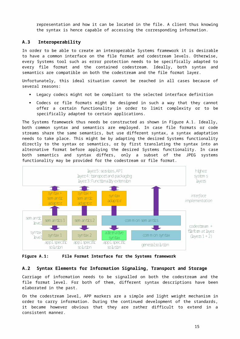
The Systems framework thus needs be constructed as shown in Figure A.1. Ideally, both common syntax and semantics are employed. In case file formats or code streams share the same semantics, but use different syntax, a syntax adaptation needs to take place. This might be by adapting the desired Systems functionality directly to the syntax or semantics, or by first translating the syntax into an alternative format before applying the desired Systems functionality. In case both semantics and syntax differs, only a subset of the JPEG systems functionality may be provided for the codestream or file format.
common semantics
syntax 1 syntax 2
semantics 1 semantics 2
syntaxlevel
semanticlevel
alternative syntax common syntax
general solutionappl. specific solution
syntax + semantic adaptor
syntax + semantic adaptor
syntax adaptor
layer 5: services, APIlayer 4: transport and packaginglayer 3: Functionality extension
codestream + fileformat layer
(layers 1 + 2)
interfaceimplementation
highersystemslayers
appl. specific solution
appl. specific solution
Figure A.1: File Format Interface for the Systems framework
A.2 Syntax Elements for Information Signaling, Transport and StorageCarriage of information needs to be signalled on both the codestream and the file format level. For both of them, different syntax descriptions have been elaborated in the past.
On the codestream level, APP markers are a simple and light weight mechanism in order to carry information. During the continued development of the standards, it became however obvious that they are rather difficult to extend in a consistent manner.
The box based structure is a much more generic approach that has its origins in different file formats (i.e. ISO/IEC 15444-1). Nevertheless, it can also be used to carry information within codestreams as standardized in ISO/IEC 18477-3. Due to its flexibility, this is the preferred approach for all future coding standards.
Finally, alternative file format syntax (i.e. TIFF-based) have been developed in the past. Nevertheless, box-based file formats are preferred for future developments.
13
Annex B: Concept of Boxes
(This annex forms an integral part of this Recommendation | International Standard)
B.1 IntroductionThis annex defines the concept of boxes and list all used boxes in JPEG standards.
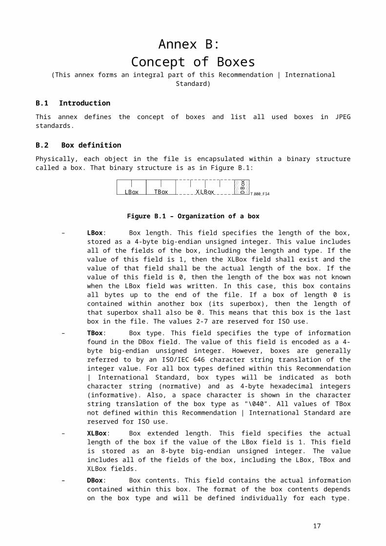
B.2 Box definitionPhysically, each object in the file is encapsulated within a binary structure called a box. That binary structure is as in Figure B.1:
T.800_FI-4LBox TBox XLBox DB
ox
Figure B.1 – Organization of a box
– LBox: Box length. This field specifies the length of the box, stored as a 4-byte big-endian unsigned integer. This value includes all of the fields of the box, including the length and type. If the value of this field is 1, then the XLBox field shall exist and the value of that field shall be the actual length of the box. If the value of this field is 0, then the length of the box was not known when the LBox field was written. In this case, this box contains all bytes up to the end of the file. If a box of length 0 is contained within another box (its superbox), then the length of that superbox shall also be 0. This means that this box is the last box in the file. The values 2-7 are reserved for ISO use.
– TBox: Box type. This field specifies the type of information found in the DBox field. The value of this field is encoded as a 4-byte big-endian unsigned integer. However, boxes are generally referred to by an ISO/IEC 646 character string translation of the integer value. For all box types defined within this Recommendation | International Standard, box types will be indicated as both character string (normative) and as 4-byte hexadecimal integers (informative). Also, a space character is shown in the character string translation of the box type as "\040". All values of TBox not defined within this Recommendation | International Standard are reserved for ISO use.
– XLBox: Box extended length. This field specifies the actual length of the box if the value of the LBox field is 1. This field is stored as an 8-byte big-endian unsigned integer. The value includes all of the fields of the box, including the LBox, TBox and XLBox fields.
– DBox: Box contents. This field contains the actual information contained within this box. The format of the box contents depends on the box type and will be defined individually for each type. Depending on the concrete box type and its specification, it can include other boxes allowing thus the description of hierarchical data structures.
Table B.1 – Binary structure of a box
Field name Size (bits) Value
LBox 32 0, 1, or 8 to (232– 1)
TBox 32 Variable
XLBox 640
16 to (264– 1); if LBox = 1Not applicable; if LBox 1
DBox Variable Variable
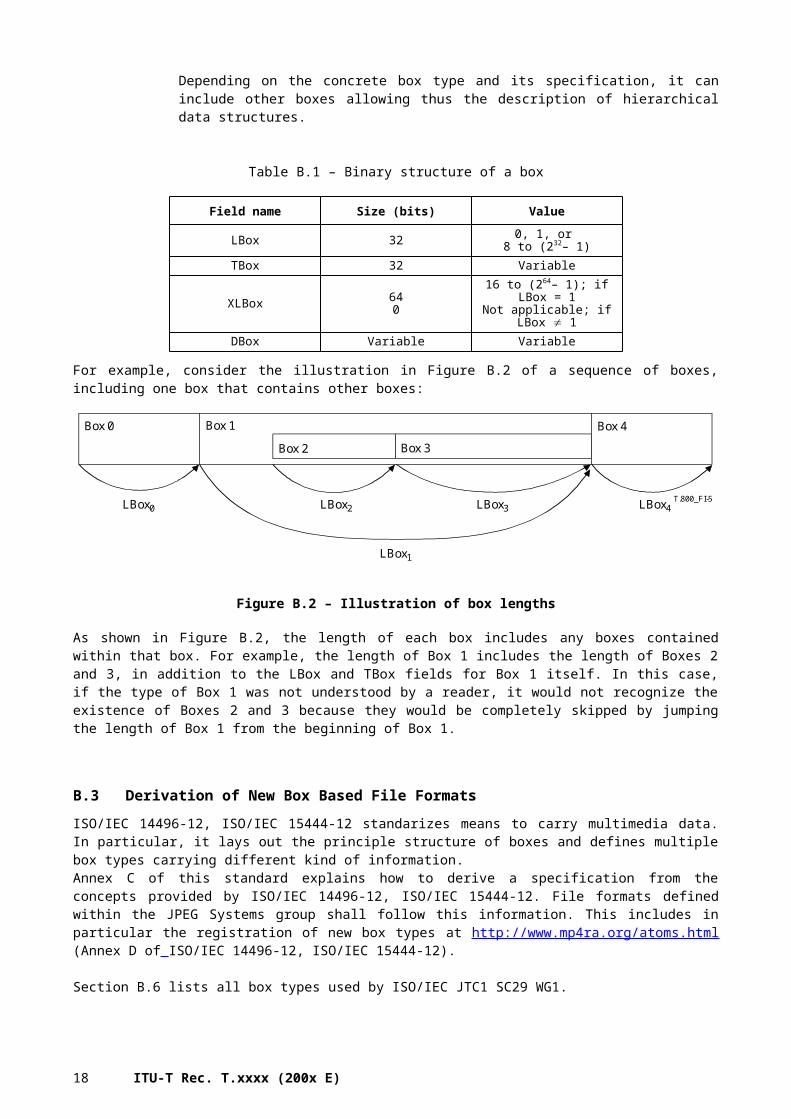
For example, consider the illustration in Figure B.2 of a sequence of boxes, including one box that contains other boxes:
14 ITU-T Rec. T.xxxx (200x E)
T.800_FI-5
Box 0 Box 1 Box 4
Box 2 Box 3
LBox0
LBox1
LBox2 LBox3 LBox4
Figure B.2 – Illustration of box lengths
As shown in Figure B.2, the length of each box includes any boxes contained within that box. For example, the length of Box 1 includes the length of Boxes 2 and 3, in addition to the LBox and TBox fields for Box 1 itself. In this case, if the type of Box 1 was not understood by a reader, it would not recognize the existence of Boxes 2 and 3 because they would be completely skipped by jumping the length of Box 1 from the beginning of Box 1.
B.3 Derivation of New Box Based File FormatsISO/IEC 14496-12, ISO/IEC 15444-12 standarizes means to carry multimedia data. In particular, it lays out the principle structure of boxes and defines multiple box types carrying different kind of information.Annex C of this standard explains how to derive a specification from the concepts provided by ISO/IEC 14496-12, ISO/IEC 15444-12. File formats defined within the JPEG Systems group shall follow this information. This includes in particular the registration of new box types at http://www.mp4ra.org/atoms.html (Annex D of ISO/IEC 14496-12, ISO/IEC 15444-12).
Section B.6 lists all box types used by ISO/IEC JTC1 SC29 WG1.
B.4 Carriage mechanisms for box structures within codestreamsBox structures enable the storage of huge amounts of data, possibly hierarchically structured. They provide thus a powerful means for flexible interaction with coded data.
While future standards are hence encouraged to follow this design strategy, standards from the early WG1 activities do not follow this approach. Nevertheless it is recommended to design possible extensions in a box-based approach in order to support a harmonized Systems ecosystem.
An example how boxes can be carried in a forward compatible way is given in ISO/IEC 18477-3 Annex A. The basic idea is to carry boxes in APP11 markers, as they are ignored by all decoders not being able to interpret these markers. As however APP11 markers are limited in size, boxes need to be truncated into junks that can be carried by individual APP11 markers. Moreover, the order of the APP11 is not enforced and hence subject to change.
Given these constraints, the following design rules shall be followed: In case multiple instances of a certain box type can appear within a file, it has to be
ensured that the decoder can reliably identify the different box instances. While this is a very general problem (see Annex B.3), cutting boxes into multiple segments and transporting them individually makes this much more tricky, because a given box segment might not contain this identifier. Hence, the decoder is not able to identify the box instance to which the box segment belongs to. Consequently, unique box segment identifiers shall be supplied as exemplified in ISO/IEC 18477-3 Annex A.
15
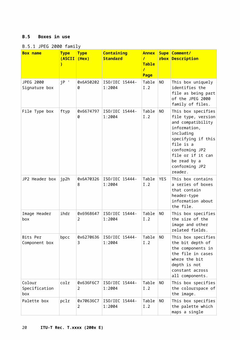
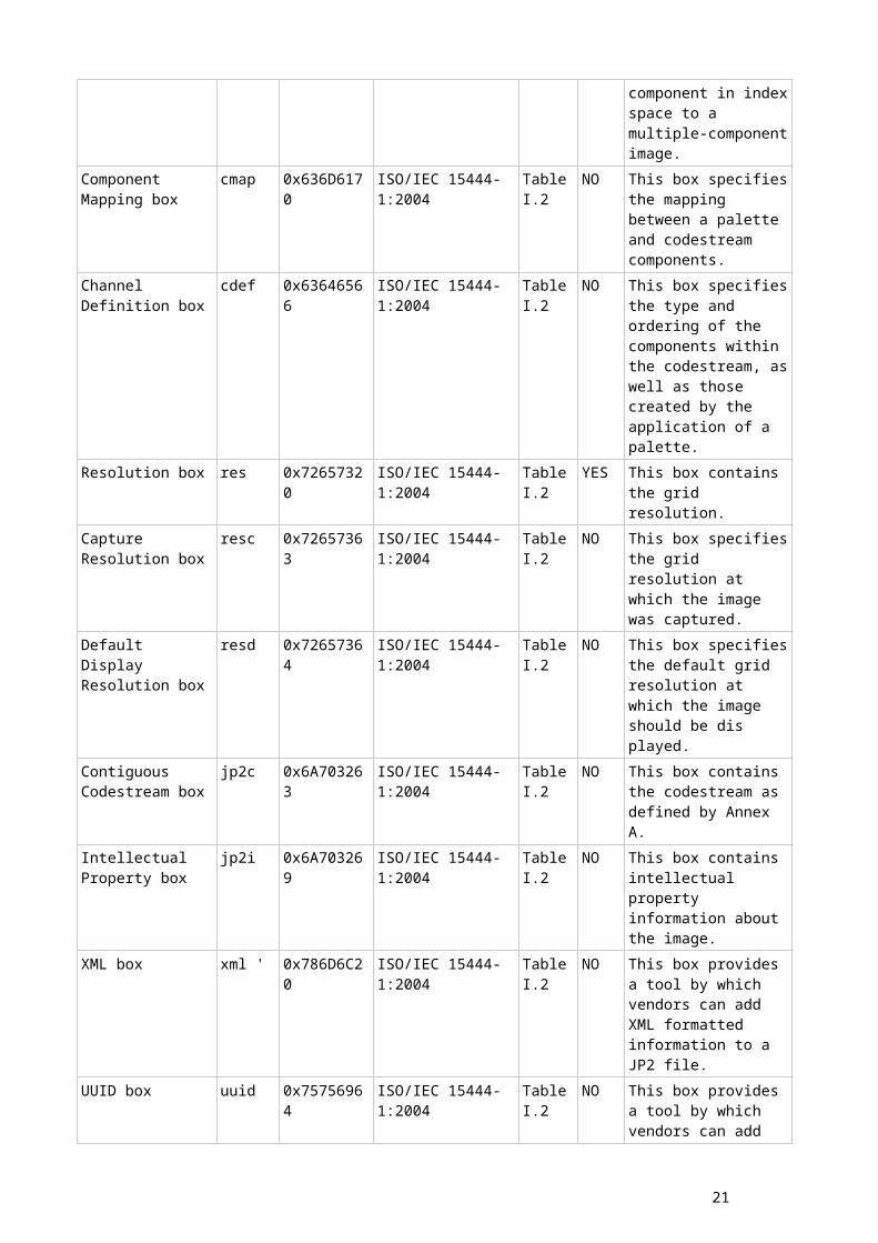
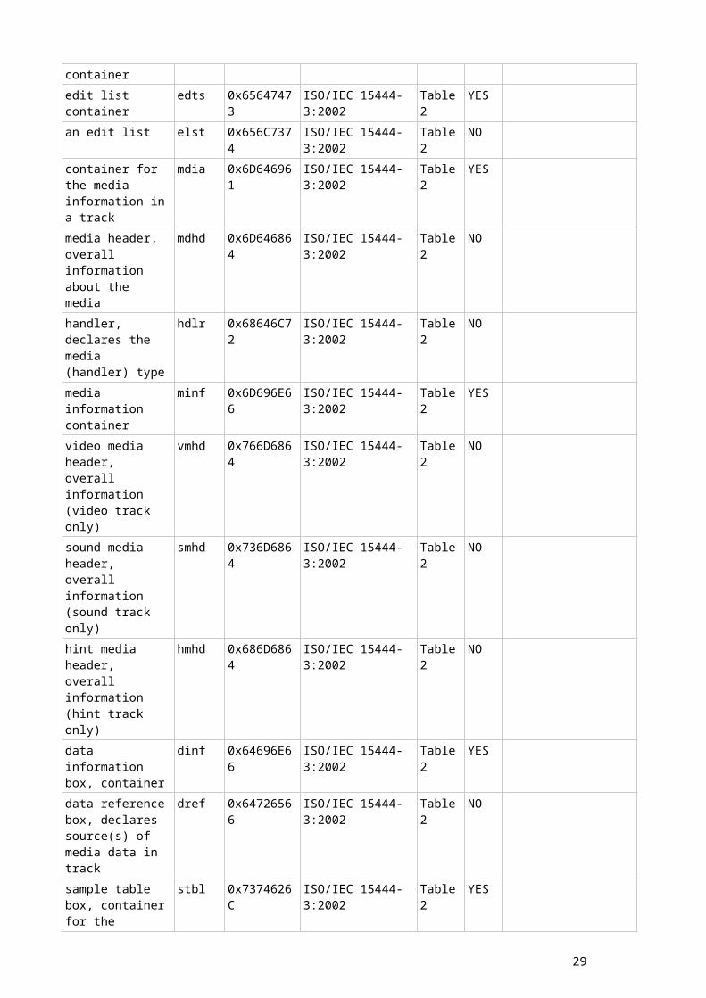
B.5 Boxes in use
B.5.1 JPEG 2000 familyBox name Type
(ASCII)Type (Hex) Containing Standard Annex/
Table/ Page
Superbox
Comment/Description
JPEG 2000 Signature box
jP ' 0x6A502020 ISO/IEC 15444-1:2004 Table I.2
NO This box uniquely identifies the file as being part of the JPEG 2000 family of files.
File Type box ftyp 0x66747970 ISO/IEC 15444-1:2004 Table I.2
NO This box specifies file type, version and compatibility information, including specifying if this file is a conforming JP2 file or if it can be read by a conforming JP2 reader.
JP2 Header box jp2h 0x6A703268 ISO/IEC 15444-1:2004 Table I.2
YES This box contains a series of boxes that contain header-type information about the file.
Image Header box ihdr 0x69686472 ISO/IEC 15444-1:2004 Table I.2
NO This box specifies the size of the image and other related fields.
Bits Per Component box
bpcc 0x62706363 ISO/IEC 15444-1:2004 Table I.2
NO This box specifies the bit depth of the components in the file in cases where the bit depth is not constant across all components.
Colour Specification box
colr 0x636F6C72 ISO/IEC 15444-1:2004 Table I.2
NO This box specifies the colourspace of the image.
Palette box pclr 0x70636C72 ISO/IEC 15444-1:2004 Table I.2
NO This box specifies the palette which maps a single component in index space to a multiple-component image.
Component Mapping box
cmap 0x636D6170 ISO/IEC 15444-1:2004 Table I.2
NO This box specifies the mapping between a palette and codestream components.
Channel Definition box
cdef 0x63646566 ISO/IEC 15444-1:2004 Table I.2
NO This box specifies the type and ordering of the components within the codestream, as well as those created by the application of a palette.
Resolution box res 0x72657320 ISO/IEC 15444-1:2004 Table I.2
YES This box contains the grid resolution.
Capture Resolution box
resc 0x72657363 ISO/IEC 15444-1:2004 Table I.2
NO This box specifies the grid resolution at which the image was captured.
Default Display Resolution box
resd 0x72657364 ISO/IEC 15444-1:2004 Table I.2
NO This box specifies the default grid resolution at which the image should be dis played.
Contiguous jp2c 0x6A703263 ISO/IEC 15444-1:2004 Table NO This box contains the
16 ITU-T Rec. T.xxxx (200x E)
Codestream box I.2 codestream as defined by Annex A.
Intellectual Property box
jp2i 0x6A703269 ISO/IEC 15444-1:2004 Table I.2
NO This box contains intellectual property information about the image.
XML box xml ' 0x786D6C20 ISO/IEC 15444-1:2004 Table I.2
NO This box provides a tool by which vendors can add XML formatted information to a JP2 file.
UUID box uuid 0x75756964 ISO/IEC 15444-1:2004 Table I.2
NO This box provides a tool by which vendors can add additional information to a file without risking conflict with other vendors.
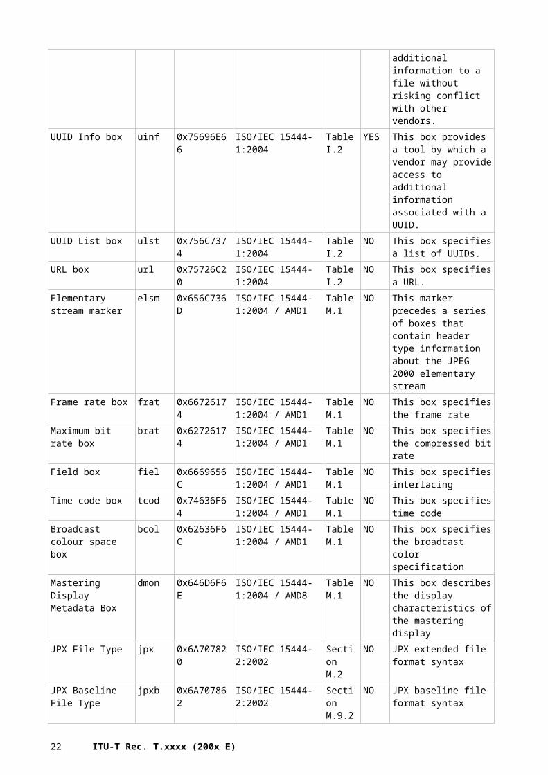
UUID Info box uinf 0x75696E66 ISO/IEC 15444-1:2004 Table I.2
YES This box provides a tool by which a vendor may provide access to additional information associated with a UUID.
UUID List box ulst 0x756C7374 ISO/IEC 15444-1:2004 Table I.2
NO This box specifies a list of UUIDs.
URL box url 0x75726C20 ISO/IEC 15444-1:2004 Table I.2
NO This box specifies a URL.
Elementary stream marker
elsm 0x656C736D ISO/IEC 15444-1:2004 / AMD1
Table M.1
NO This marker precedes a series of boxes that contain header type information about the JPEG 2000 elementary stream
Frame rate box frat 0x66726174 ISO/IEC 15444-1:2004 / AMD1
Table M.1
NO This box specifies the frame rate
Maximum bit rate box brat 0x62726174 ISO/IEC 15444-1:2004 / AMD1
Table M.1
NO This box specifies the compressed bit rate
Field box fiel 0x6669656C ISO/IEC 15444-1:2004 / AMD1
Table M.1
NO This box specifies interlacing
Time code box tcod 0x74636F64 ISO/IEC 15444-1:2004 / AMD1
Table M.1
NO This box specifies time code
Broadcast colour space box
bcol 0x62636F6C ISO/IEC 15444-1:2004 / AMD1
Table M.1
NO This box specifies the broadcast color specification
Mastering Display Metadata Box
dmon 0x646D6F6E ISO/IEC 15444-1:2004 / AMD8
Table M.1
NO This box describes the display characteristics of the mastering display
JPX File Type jpx 0x6A707820 ISO/IEC 15444-2:2002 Section M.2
NO JPX extended file format syntax
JPX Baseline File Type
jpxb 0x6A707862 ISO/IEC 15444-2:2002 Section M.9.2
NO JPX baseline file format syntax
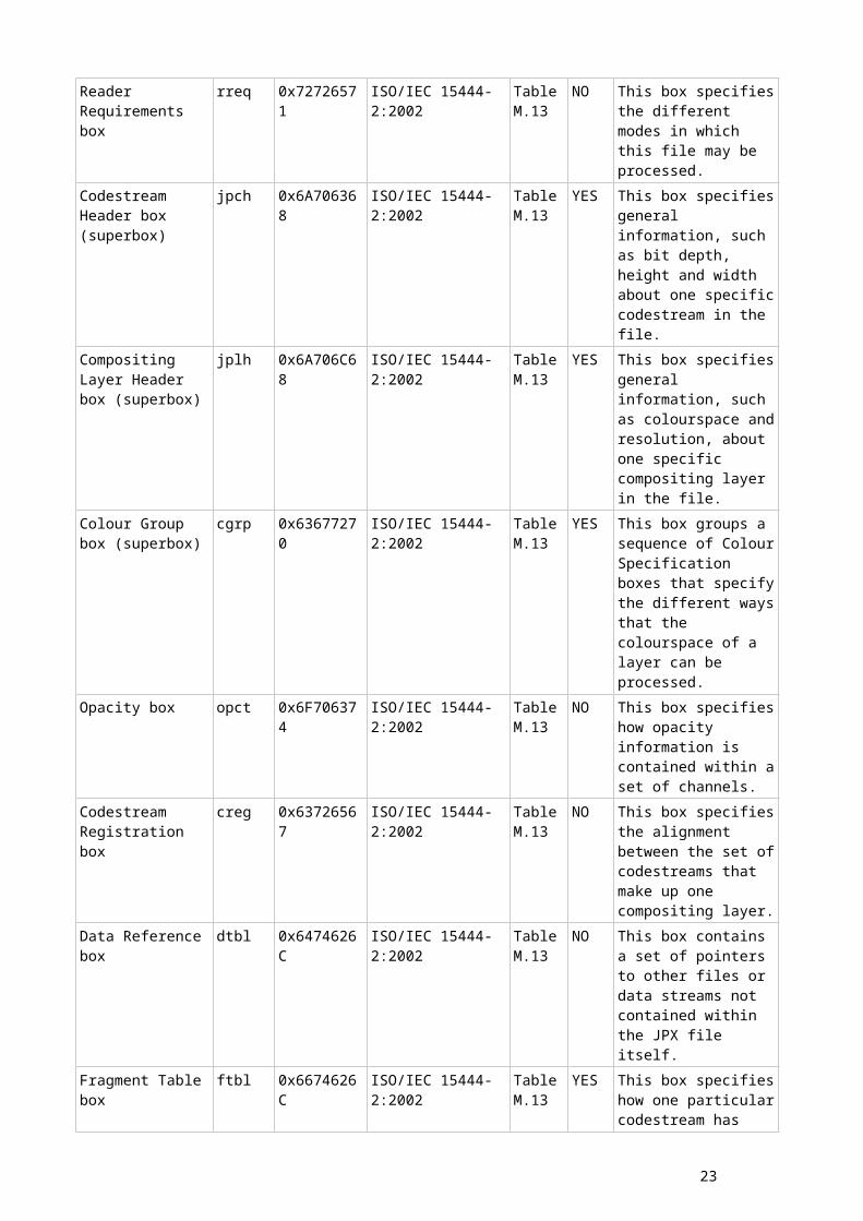
Reader Requirements box
rreq 0x72726571 ISO/IEC 15444-2:2002 Table M.13
NO This box specifies the different modes in which this file may be processed.
Codestream Header box (superbox)
jpch 0x6A706368 ISO/IEC 15444-2:2002 Table M.13
YES This box specifies general information, such as bit depth, height and width about one specific codestream in the file.
Compositing Layer jplh 0x6A706C68 ISO/IEC 15444-2:2002 Table YES This box specifies general
17
Header box (superbox)
M.13 information, such as colourspace and resolution, about one specific compositing layer in the file.
Colour Group box (superbox)
cgrp 0x63677270 ISO/IEC 15444-2:2002 Table M.13
YES This box groups a sequence of Colour Specification boxes that specify the different ways that the colourspace of a layer can be processed.
Opacity box opct 0x6F706374 ISO/IEC 15444-2:2002 Table M.13
NO This box specifies how opacity information is contained within a set of channels.
Codestream Registration box
creg 0x63726567 ISO/IEC 15444-2:2002 Table M.13
NO This box specifies the alignment between the set of codestreams that make up one compositing layer.
Data Reference box dtbl 0x6474626C ISO/IEC 15444-2:2002 Table M.13
NO This box contains a set of pointers to other files or data streams not contained within the JPX file itself.
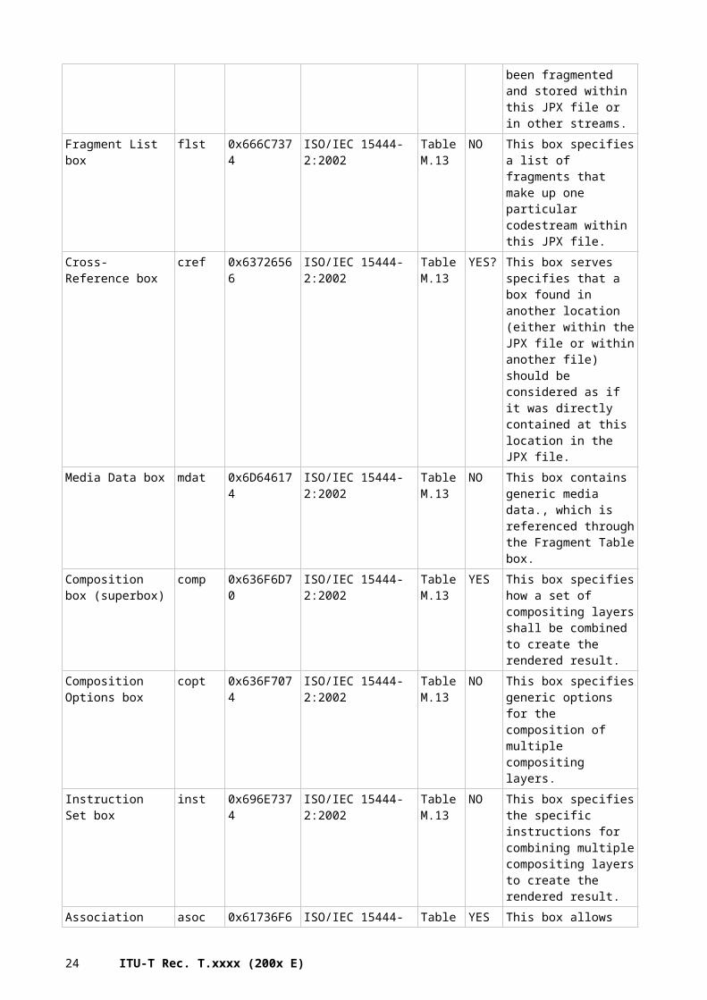
Fragment Table box ftbl 0x6674626C ISO/IEC 15444-2:2002 Table M.13
YES This box specifies how one particular codestream has been fragmented and stored within this JPX file or in other streams.
Fragment List box flst 0x666C7374 ISO/IEC 15444-2:2002 Table M.13
NO This box specifies a list of fragments that make up one particular codestream within this JPX file.
Cross-Reference box cref 0x63726566 ISO/IEC 15444-2:2002 Table M.13
YES? This box serves specifies that a box found in another location (either within the JPX file or within another file) should be considered as if it was directly contained at this location in the JPX file.
Media Data box mdat 0x6D646174 ISO/IEC 15444-2:2002 Table M.13
NO This box contains generic media data., which is referenced through the Fragment Table box.
Composition box (superbox)
comp 0x636F6D70 ISO/IEC 15444-2:2002 Table M.13
YES This box specifies how a set of compositing layers shall be combined to create the rendered result.
Composition Options box
copt 0x636F7074 ISO/IEC 15444-2:2002 Table M.13
NO This box specifies generic options for the composition of multiple compositing layers.
Instruction Set box inst 0x696E7374 ISO/IEC 15444-2:2002 Table M.13
NO This box specifies the specific instructions for combining multiple compositing layers to create the rendered result.
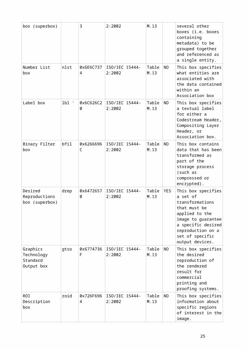
Association box (superbox)
asoc 0x61736F63 ISO/IEC 15444-2:2002 Table M.13
YES This box allows several other boxes (i.e. boxes
18 ITU-T Rec. T.xxxx (200x E)
containing metadata) to be grouped together and referenced as a single entity.
Number List box nlst 0x6E6C7374 ISO/IEC 15444-2:2002 Table M.13
NO This box specifies what entities are associated with the data contained within an Association box
Label box lbl ' 0x6C626C20 ISO/IEC 15444-2:2002 Table M.13
NO This box specifies a textual label for either a Codestream Header, Compositing Layer Header, or Association box.
Binary Filter box bfil 0x6266696C ISO/IEC 15444-2:2002 Table M.13
NO This box contains data that has been transformed as part of the storage process (such as compressed or encrypted).
Desired Reproductions box (superbox)
drep 0x64726570 ISO/IEC 15444-2:2002 Table M.13
YES This box specifies a set of transformations that must be applied to the image to guarantee a specific desired reproduction on a set of specific output devices.
Graphics Technology Standard Output box
gtso 0x6774736F ISO/IEC 15444-2:2002 Table M.13
NO This box specifies the desired reproduction of the rendered result for commercial printing and proofing systems.
ROI Description box roid 0x726F6964 ISO/IEC 15444-2:2002 Table M.13
NO This box specifies information about specific regions of interest in the image.
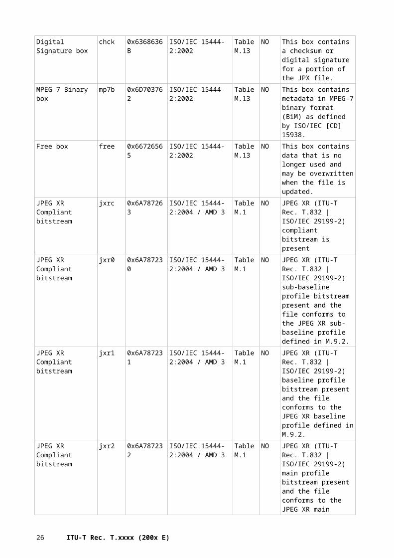
Digital Signature box chck 0x6368636B ISO/IEC 15444-2:2002 Table M.13
NO This box contains a checksum or digital signature for a portion of the JPX file.
MPEG-7 Binary box mp7b 0x6D703762 ISO/IEC 15444-2:2002 Table M.13
NO This box contains metadata in MPEG-7 binary format (BiM) as defined by ISO/IEC [CD] 15938.
Free box free 0x66726565 ISO/IEC 15444-2:2002 Table M.13
NO This box contains data that is no longer used and may be overwritten when the file is updated.
JPEG XR Compliant bitstream
jxrc 0x6A787263 ISO/IEC 15444-2:2004 / AMD 3
Table M.1
NO JPEG XR (ITU-T Rec. T.832 | ISO/IEC 29199-2) compliant bitstream is present
JPEG XR Compliant bitstream
jxr0 0x6A787230 ISO/IEC 15444-2:2004 / AMD 3
Table M.1
NO JPEG XR (ITU-T Rec. T.832 | ISO/IEC 29199-2) sub-baseline profile bitstream present and the file conforms to the JPEG XR sub-baseline profile defined in M.9.2.
19
JPEG XR Compliant bitstream
jxr1 0x6A787231 ISO/IEC 15444-2:2004 / AMD 3
Table M.1
NO JPEG XR (ITU-T Rec. T.832 | ISO/IEC 29199-2) baseline profile bitstream present and the file conforms to the JPEG XR baseline profile defined in M.9.2.
JPEG XR Compliant bitstream
jxr2 0x6A787232 ISO/IEC 15444-2:2004 / AMD 3
Table M.1
NO JPEG XR (ITU-T Rec. T.832 | ISO/IEC 29199-2) main profile bitstream present and the file conforms to the JPEG XR main profile defined in M.9.2.
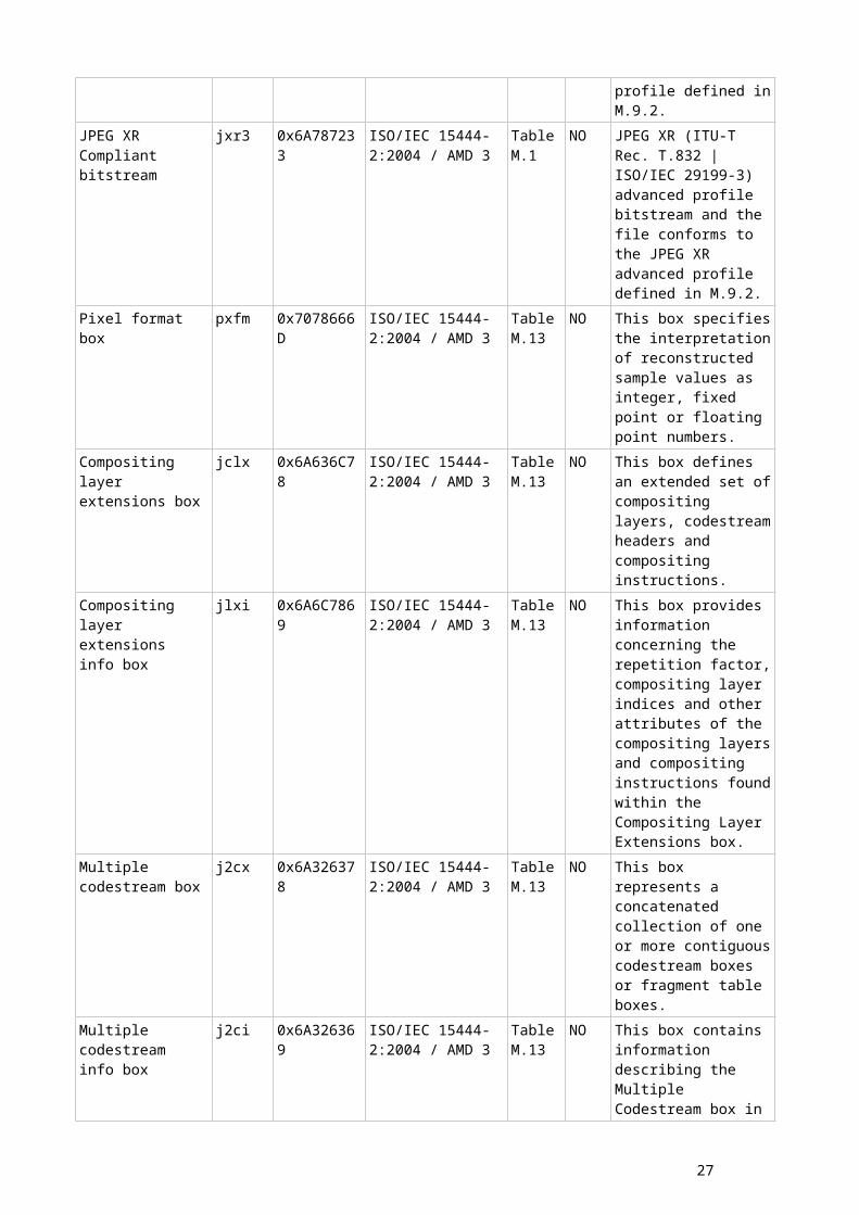
JPEG XR Compliant bitstream
jxr3 0x6A787233 ISO/IEC 15444-2:2004 / AMD 3
Table M.1
NO JPEG XR (ITU-T Rec. T.832 | ISO/IEC 29199-3) advanced profile bitstream and the file conforms to the JPEG XR advanced profile defined in M.9.2.
Pixel format box pxfm 0x7078666D ISO/IEC 15444-2:2004 / AMD 3
Table M.13
NO This box specifies the interpretation of reconstructed sample values as integer, fixed point or floating point numbers.
Compositing layer extensions box
jclx 0x6A636C78 ISO/IEC 15444-2:2004 / AMD 3
Table M.13
NO This box defines an extended set of compositing layers, codestream headers and compositing instructions.
Compositing layer extensions info box
jlxi 0x6A6C7869 ISO/IEC 15444-2:2004 / AMD 3
Table M.13
NO This box provides information concerning the repetition factor, compositing layer indices and other attributes of the compositing layers and compositing instructions found within the Compositing Layer Extensions box.
Multiple codestream box
j2cx 0x6A326378 ISO/IEC 15444-2:2004 / AMD 3
Table M.13
NO This box represents a concatenated collection of one or more contiguous codestream boxes or fragment table boxes.
Multiple codestream info box
j2ci 0x6A326369 ISO/IEC 15444-2:2004 / AMD 3
Table M.13
NO This box contains information describing the Multiple Codestream box in which it is found.
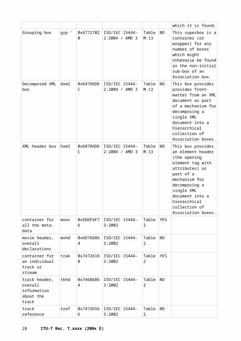
Grouping box grp ' 0x67727020 ISO/IEC 15444-2:2004 / AMD 3
Table M.13
NO This superbox is a container (or wrapper) for any number of boxes which might otherwise be found as the non-initial sub-box of an Association box.
Decomposed XML box
dxml 0x64786D6C ISO/IEC 15444-2:2004 / AMD 3
Table M.13
NO This box provides provides front-matter from an XML document as part
20 ITU-T Rec. T.xxxx (200x E)
of a mechanism for decomposing a single XML document into a hierarchical collection of Association boxes.
XML header box hxml 0x68786D6C ISO/IEC 15444-2:2004 / AMD 3
Table M.13
NO This box provides an element header (the opening element tag with attributes) as part of a mechanism for decomposing a single XML document into a hierarchical collection of Association boxes.
container for all the meta-data
moov 0x6D6F6F76 ISO/IEC 15444-3:2002 Table 2 YES
movie header, overall declarations
mvhd 0x6D766864 ISO/IEC 15444-3:2002 Table 2 NO
container for an individual track or stream
trak 0x7472616B ISO/IEC 15444-3:2002 Table 2 YES
track header, overall information about the track
tkhd 0x746B6864 ISO/IEC 15444-3:2002 Table 2 NO
track reference container
tref 0x74726566 ISO/IEC 15444-3:2002 Table 2 NO
edit list container edts 0x65647473 ISO/IEC 15444-3:2002 Table 2 YESan edit list elst 0x656C7374 ISO/IEC 15444-3:2002 Table 2 NOcontainer for the media information in a track
mdia 0x6D646961 ISO/IEC 15444-3:2002 Table 2 YES
media header, overall information about the media
mdhd 0x6D646864 ISO/IEC 15444-3:2002 Table 2 NO
handler, declares the media (handler) type
hdlr 0x68646C72 ISO/IEC 15444-3:2002 Table 2 NO
media information container
minf 0x6D696E66 ISO/IEC 15444-3:2002 Table 2 YES
video media header, overall information (video track only)
vmhd 0x766D6864 ISO/IEC 15444-3:2002 Table 2 NO
sound media header, overall information (sound track only)
smhd 0x736D6864 ISO/IEC 15444-3:2002 Table 2 NO
hint media header, overall information (hint track only)
hmhd 0x686D6864 ISO/IEC 15444-3:2002 Table 2 NO
data information box, container
dinf 0x64696E66 ISO/IEC 15444-3:2002 Table 2 YES
data reference box, declares source(s) of media data in track
dref 0x64726566 ISO/IEC 15444-3:2002 Table 2 NO
sample table box, container for the time/space map
stbl 0x7374626C ISO/IEC 15444-3:2002 Table 2 YES
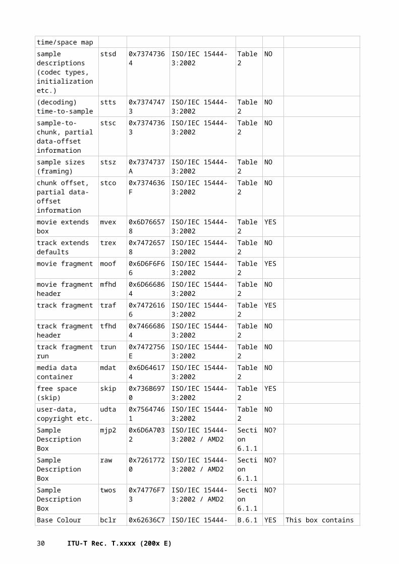
sample descriptions stsd 0x73747364 ISO/IEC 15444-3:2002 Table 2 NO
21
(codec types, initialization etc.)(decoding) time-to-sample
stts 0x73747473 ISO/IEC 15444-3:2002 Table 2 NO
sample-to-chunk, partial data-offset information
stsc 0x73747363 ISO/IEC 15444-3:2002 Table 2 NO
sample sizes (framing)
stsz 0x7374737A ISO/IEC 15444-3:2002 Table 2 NO
chunk offset, partial data-offset information
stco 0x7374636F ISO/IEC 15444-3:2002 Table 2 NO
movie extends box mvex 0x6D766578 ISO/IEC 15444-3:2002 Table 2 YEStrack extends defaults trex 0x74726578 ISO/IEC 15444-3:2002 Table 2 NOmovie fragment moof 0x6D6F6F66 ISO/IEC 15444-3:2002 Table 2 YESmovie fragment header
mfhd 0x6D666864 ISO/IEC 15444-3:2002 Table 2 NO
track fragment traf 0x74726166 ISO/IEC 15444-3:2002 Table 2 YEStrack fragment header tfhd 0x74666864 ISO/IEC 15444-3:2002 Table 2 NOtrack fragment run trun 0x7472756E ISO/IEC 15444-3:2002 Table 2 NOmedia data container mdat 0x6D646174 ISO/IEC 15444-3:2002 Table 2 NOfree space (skip) skip 0x736B6970 ISO/IEC 15444-3:2002 Table 2 YESuser-data, copyright etc.
udta 0x75647461 ISO/IEC 15444-3:2002 Table 2 NO
Sample Description Box
mjp2 0x6D6A7032 ISO/IEC 15444-3:2002 / AMD2
Section 6.1.1
NO?
Sample Description Box
raw 0x72617720 ISO/IEC 15444-3:2002 / AMD2
Section 6.1.1
NO?
Sample Description Box
twos 0x74776F73 ISO/IEC 15444-3:2002 / AMD2
Section 6.1.1
NO?
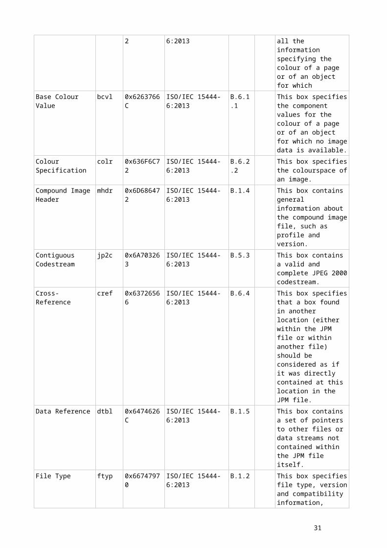
Base Colour bclr 0x62636C72 ISO/IEC 15444-6:2013 B.6.1 YES This box contains all the information specifying the colour of a page or of an object for which
Base Colour Value bcvl 0x6263766C ISO/IEC 15444-6:2013 B.6.1.1 This box specifies the component values for the colour of a page or of an object for which no image data is available.
Colour Specification colr 0x636F6C72 ISO/IEC 15444-6:2013 B.6.2.2 This box specifies the colourspace of an image.
Compound Image Header
mhdr 0x6D686472 ISO/IEC 15444-6:2013 B.1.4 This box contains general information about the compound image file, such as profile and version.
Contiguous Codestream
jp2c 0x6A703263 ISO/IEC 15444-6:2013 B.5.3 This box contains a valid and complete JPEG 2000 codestream.
Cross-Reference cref 0x63726566 ISO/IEC 15444-6:2013 B.6.4 This box specifies that a box found in another location (either within the JPM file or within another file) should be considered as if it was directly contained at this location
22 ITU-T Rec. T.xxxx (200x E)
in the JPM file.Data Reference dtbl 0x6474626C ISO/IEC 15444-6:2013 B.1.5 This box contains a set of
pointers to other files or data streams not contained within the JPM file itself.
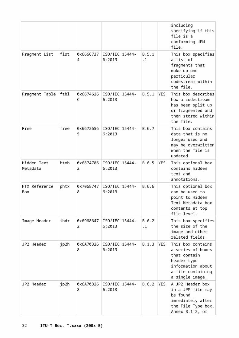
File Type ftyp 0x66747970 ISO/IEC 15444-6:2013 B.1.2 This box specifies file type, version and compatibility information, including specifying if this file is a conforming JPM file.
Fragment List flst 0x666C7374 ISO/IEC 15444-6:2013 B.5.1.1 This box specifies a list of fragments that make up one particular codestream within the file.
Fragment Table ftbl 0x6674626C ISO/IEC 15444-6:2013 B.5.1 YES This box describes how a codestream has been split up or fragmented and then stored within the file.
Free free 0x66726565 ISO/IEC 15444-6:2013 B.6.7 This box contains data that is no longer used and may be overwritten when the file is updated.
Hidden Text Metadata
htxb 0x68747862 ISO/IEC 15444-6:2013 B.6.5 YES This optional box contains hidden text and annotations.
HTX Reference Box phtx 0x70687478 ISO/IEC 15444-6:2013 B.6.6 This optional box can be used to point to Hidden Text Metadata box contents at top file level.
Image Header ihdr 0x69686472 ISO/IEC 15444-6:2013 B.6.2.1 This box specifies the size of the image and other related fields.
JP2 Header jp2h 0x6A703268 ISO/IEC 15444-6:2013 B.1.3 YES This box contains a series of boxes that contain header-type information about a file containing a single image.
JP2 Header jp2h 0x6A703268 ISO/IEC 15444-6:2013 B.6.2 YES A JP2 Header box in a JPM file may be found immediately after the File Type box, Annex B.1.2, or within an Object box, Annex B.4.1.
JP2 Header box (superbox) in Object box
jp2h 0x6A703268 ISO/IEC 15444-6:2013 B.4.1.3 YES A JP2 Header box exists within an Object box when the NoCodestream field of the Object Header box in the container Object box is 0. Within an Object box of a JPM file, there shall be one and only one JP2 Header box.
JPEG 2000 Signature jP\040\040
0x6A505C30 ISO/IEC 15444-6:2013 B.1.1 This box uniquely defines the file as being part of the JPEG 2000 family of files.
Label lbl\040 0x6C626C5C ISO/IEC 15444-6:2013 B.6.3 This box specifies a textual label for a Page
23
box or a Page Collection box.
Layout Object lobj 0x6C6F626A ISO/IEC 15444-6:2013 B.3.1 YES This box contains the information and image data needed to composite a mask-image object pair.
Layout Object Header lhdr 0x6C686472 ISO/IEC 15444-6:2013 B.3.1.1 This box describes the properties of the layout object and assigns each a unique identifier within the page.
Media Data mdat 0x6D646174 ISO/IEC 15444-6:2013 B.5.2 This box contains generic media data, which is referenced through the Fragment List box.
Object objc 0x6F626A63 ISO/IEC 15444-6:2013 B.4.1 YES This box contains all the image data and information for one object in a layout object.
Object Header ohdr 0x6F686472 ISO/IEC 15444-6:2013 B.4.1.1 This box describes the properties of an object, identifying it as a mask, an image or a combined mask/image object, and assigns each object a unique identifier within the file.
Object Scale scal 0x7363616C ISO/IEC 15444-6:2013 B.4.1.2 This box describes the scaling for an object before applying it to the page.
Page page 0x70616765 ISO/IEC 15444-6:2013 B.2.1 YES This box contains all the information needed to image a page including references to codestream data.
Page Collection pcol 0x70636F6C ISO/IEC 15444-6:2013 B.1.6 YES This box groups together the locations of a set of pages so that they are treated as related and associated with each other.
Page Header phdr 0x70686472 ISO/IEC 15444-6:2013 B.2.1.1 This box describes the properties of a page and gives the number of layout objects in the page.
Page Table pagt 0x70616774 ISO/IEC 15444-6:2013 B.1.6.2 This box gives the locations of the pages in a page collection and enables random access of pages in a file.
Primary Page Collection Locator
ppcl 0x7070636C ISO/IEC 15444-6:2013 B.1.6.1 This box gives the location of the primary page collection for the page collection.
Shared Data Entry sdat 0x73646174 ISO/IEC 15444-6:2013 B.1.7 YES This box contains a box that can be referenced by an identifier from multiple places within a file.
24 ITU-T Rec. T.xxxx (200x E)
Shared Data Reference
sref 0x73726566 ISO/IEC 15444-6:2013 B.1.8 This box can be used to insert a box in the file by reference to a previous occurrence of the box in the same file.
UUID uuid 0x75756964 ISO/IEC 15444-6:2013 C.2.2 This box contains vendor specific information.
UUID Info uinf 0x75696E66 ISO/IEC 15444-6:2013 C.2.3 YES This box contains additional information associated with a UUID.
XML xml\040 0x786D6C5C ISO/IEC 15444-6:2013 C.2.1 This box contains vendor specific information in XML format.
Granularity gran 0x6772616E ISO/IEC 15444-8:2007 / Amd.1
E.3.5 granularity is used for item-based protection.
ValueList vall 0x76616C6C ISO/IEC 15444-8:2007 / Amd.1
E.3.5
KeyTemplate keyt 0x6B657974 ISO/IEC 15444-8:2007 / Amd.1
E.3.5
BlockCipher bcip 0x62636970 ISO/IEC 15444-8:2007 / Amd.1
E.3.5
StreamCipher scip 0x73636970 ISO/IEC 15444-8:2007 / Amd.1
E.3.5
SchemeInfomation schi 0x73636869 ISO/IEC 15444-8:2007 / Amd.1
E.3.5
Auth Auth 0x41757468 ISO/IEC 15444-8:2007 / Amd.1
E.3.6
SchemeInfo schi 0x73636869 ISO/IEC 15444-8:2007 / Amd.1
E.3.6
ItemDescription ides 0x69646573 ISO/IEC 15444-8:2007 / Amd.1
E.3.7
DescriptionType dest 0x64657374 ISO/IEC 15444-8:2007 / Amd.1
E.3.7
DescriptionData desd 0x64657364 ISO/IEC 15444-8:2007 / Amd.1
E.3.7
VisualItemDescriptionEntry
vide 0x76696465 ISO/IEC 15444-8:2007 / Amd.1
E.3.7
J2KItemDescriptionEntry
j2ke 0x6A326B65 ISO/IEC 15444-8:2007 / Amd.1
E.3.7
ItemCorrespondenceEntry
icor 0x69636F72 ISO/IEC 15444-8:2007 / Amd.1
E.3.7
ScalableSampleDescriptionEntry
? ? ISO/IEC 15444-8:2007 / Amd.1
E.3.8
ScalableSampleGroupEntry
? ? ISO/IEC 15444-8:2007 / Amd.1
E.3.9
JProtectedBox gprt 0x67707274 ISO/IEC 15444-8:2007 / Amd.1
E.3.10
Placeholder phld 0x70686C64 ISO/IEC 15444-9:2005 A.3.6.3 identify the size and type of a box from the logical target, while pointing to another data-bin that holds that box's contents
Codestream index box
cidx 0x63696478 ISO/IEC 15444-9:2005 I.3.2 YES This box contains indexing information about a JPEG 2000 codestream.
25
Codestream Finder box
cptr 0x63707472 ISO/IEC 15444-9:2005 I.3.2.2 This box points to a JPEG 2000 codestream.
Header Index Table box
mhix 0x6D686978 ISO/IEC 15444-9:2005 I.3.2.4.3 This box specifies an index of the marker segments in the main header of a codestream or the tile-part headers of a tile.
Tile-part Index Table box
tpix 0x74706978 ISO/IEC 15444-9:2005 I.3.2.4.4 YES This box specifies the locations and lengths of each tile- part in the codestream.
Tile Header Index Table box
thix 0x74686978 ISO/IEC 15444-9:2005 I.3.2.4.5 YES This box specifies the locations and lengths of each part of the codestream necessary to construct tile headers for each tile for the correct decoding of precinct packet data.
Precinct Packet Index Table box
ppix 0x70706978 ISO/IEC 15444-9:2005 I.3.2.4.6 YES This box specifies the locations and lengths of packets within the codestream.
Packet Header Index Table box
phix 0x70686978 ISO/IEC 15444-9:2005 I.3.2.4.7 YES This box specifies the locations and lengths of packet headers within the codestream.
Manifest box manf 0x6D616E66 ISO/IEC 15444-9:2005 I.3.2.3 This box summarizes the boxes that immediately and contiguously follow it, within its containing box or file at the same level as the Manifest box.
Fragment Array Index box
faix 0x66616978 ISO/IEC 15444-9:2005 I.3.2.4.2 This box specifies the locations and lengths of the elements of a codestream.
File Index box fidx 0x66696478 ISO/IEC 15444-9:2005 I.3.3 YES This box can be used to find other indexes and arbitrary data within the file
File Finder box fptr 0x66707472 ISO/IEC 15444-9:2005 I.3.3.2 This box points to an indexed box
Proxy box prxy 0x70727879 ISO/IEC 15444-9:2005 I.3.3.3 This box represents in a File Index box a box elsewhere in the file
Index Finder box iptr 0x69707472 ISO/IEC 15444-9:2005 I.3.4 This box points to the root File Index box of a file.
File Type box ftyp 0x66747970 ISO/IEC 15444-12:2012
4.3.1
Media Data box mdat 0x6D646174 ISO/IEC 15444-12:2012
8.1.1
Free Space Box free 0x66726565 ISO/IEC 15444-12:2012
8.1.2
Free Space Box skip 0x736B6970 ISO/IEC 15444-12:2012
8.1.2
26 ITU-T Rec. T.xxxx (200x E)
Progressive Download Information Box
pdin 0x7064696E ISO/IEC 15444-12:2012
8.1.3
Movie Box moov 0x6D6F6F76 ISO/IEC 15444-12:2012
8.2.1
Movie Header Box mvhd 0x6D766864 ISO/IEC 15444-12:2012
8.2.2
Track Box trak 0x7472616B ISO/IEC 15444-12:2012
8.3.1
Track Header Box tkhd 0x746B6864 ISO/IEC 15444-12:2012
8.3.2
Track Reference Box tref 0x74726566 ISO/IEC 15444-12:2012
8.3.3
Track Group Box trgr 0x74726772 ISO/IEC 15444-12:2012
8.3.4
Media Box (Track Media Structure)
mdia 0x6D646961 ISO/IEC 15444-12:2012
8.4.1
Media Header Box (Track Media Structure)
mdhd 0x6D646864 ISO/IEC 15444-12:2012
8.4.2
Handler Reference Box
hdlr 0x68646C72 ISO/IEC 15444-12:2012
8.4.3
Media Information Box
minf 0x6D696E66 ISO/IEC 15444-12:2012
8.4.4
Media Information Header Box
vmhd 0x766D6864 ISO/IEC 15444-12:2012
8.4.5
Media Information Header Box
smhd 0x736D6864 ISO/IEC 15444-12:2012
8.4.5
Media Information Header Box
hmhd 0x686D6864 ISO/IEC 15444-12:2012
8.4.5
Media Information Header Box
nmhd 0x6E6D6864 ISO/IEC 15444-12:2012
8.4.5
Sample Table Box stbl 0x7374626C ISO/IEC 15444-12:2012
8.5.1
Sample Description Box
stsd 0x73747364 ISO/IEC 15444-12:2012
8.5.2
Degradation Priority Box
stdp 0x73746470 ISO/IEC 15444-12:2012
8.5.3
Decoding Time to Sample Box
stts 0x73747473 ISO/IEC 15444-12:2012
8.6.1.2
Composition Time to Sample Box
ctts 0x63747473 ISO/IEC 15444-12:2012
8.6.1.3
Composition to Decode Box
cslg 0x63736C67 ISO/IEC 15444-12:2012
8.6.1.4
Sync Sample Box stss 0x73747373 ISO/IEC 15444-12:2012
8.6.2
Shadow Sync Sample Box
stsh 0x73747368 ISO/IEC 15444-12:2012
8.6.3
Independent and Disposable Samples Box
sdtp 0x73647470 ISO/IEC 15444-12:2012
8.6.4
Edit Box edts 0x65647473 ISO/IEC 15444-12:2012
8.6.5
Edit List Box elst 0x656C7374 ISO/IEC 15444- 8.6.6
27
12:2012data information box, container
dinf 0x64696E66 ISO/IEC 15444-12:2012
8.7.1
data reference box url ' 0x75726C20 ISO/IEC 15444-12:2012
8.7.2
urn ' 0x75726E20 ISO/IEC 15444-12:2012
8.7.2
dref 0x64726566 ISO/IEC 15444-12:2012
8.7.2
Sample Size Boxes stsz 0x7374737A ISO/IEC 15444-12:2012
8.7.3
stz2 0x73747A32 ISO/IEC 15444-12:2012
8.7.3
Sample to Chunk Box stsc 0x73747363 ISO/IEC 15444-12:2012
8.7.4
Chunk Offset Box stco 0x7374636F ISO/IEC 15444-12:2012
8.7.5
co64 0x636F3634 ISO/IEC 15444-12:2012
8.7.5
Padding Bit Box padb 0x70616462 ISO/IEC 15444-12:2012
8.7.6
Sub-Sample Information Box
subs 0x73756273 ISO/IEC 15444-12:2012
8.7.7
Sample Auxilliary Information Sizes Box
saiz 0x7361697A ISO/IEC 15444-12:2012
8.7.8
Sample Auxilliary Information Offsets Box
saio 0x7361696F ISO/IEC 15444-12:2012
8.7.9
Movie Extends Box mvex 0x6D766578 ISO/IEC 15444-12:2012
8.8.1
Movie Extends Header Box
mehd 0x6D656864 ISO/IEC 15444-12:2012
8.8.2
Track Extends Box trex 0x74726578 ISO/IEC 15444-12:2012
8.8.3
Movie Fragment Box moof 0x6D6F6F66 ISO/IEC 15444-12:2012
8.8.4
Movie Fragment Header Box
mfhd 0x6D666864 ISO/IEC 15444-12:2012
8.8.5
Track Fragment Box traf 0x74726166 ISO/IEC 15444-12:2012
8.8.6
Track Fragment Header Box
tfhd 0x74666864 ISO/IEC 15444-12:2012
8.8.7
Track Fragment Run Box
trun 0x7472756E ISO/IEC 15444-12:2012
8.8.8
Movie Fragment Random Access Box
mfra 0x6D667261 ISO/IEC 15444-12:2012
8.8.9
Track Fragment Random Access Box
tfra 0x74667261 ISO/IEC 15444-12:2012
8.8.10
Movie Fragment Random Access Offset Box
mfro 0x6D66726F ISO/IEC 15444-12:2012
8.8.11
Track Fragment Decode Time
tfdt 0x74666474 ISO/IEC 15444-12:2012
8.8.12
28 ITU-T Rec. T.xxxx (200x E)
Level Assignment Box
leva 0x6C657661 ISO/IEC 15444-12:2012
8.8.13
Sample To Group Box
sbgp 0x73626770 ISO/IEC 15444-12:2012
8.9.2
Sample Group Desrciption Box
sgpd 0x73677064 ISO/IEC 15444-12:2012
8.9.3
User Data Box udta 0x75647461 ISO/IEC 15444-12:2012
8.10.1
Copyright Box cprt 0x63707274 ISO/IEC 15444-12:2012
8.10.2
Track Selection Box tsel 0x7473656C ISO/IEC 15444-12:2012
8.10.3
The Meta Box meta 0x6D657461 ISO/IEC 15444-12:2012
8.11.1
XML Boxes xml 0x786D6C20 ISO/IEC 15444-12:2012
8.11.2
bxml 0x62786D6C ISO/IEC 15444-12:2012
8.11.2
The Item Location Box
iloc 0x696C6F63 ISO/IEC 15444-12:2012
8.11.3
Primary Item Box pitm 0x7069746D ISO/IEC 15444-12:2012
8.11.4
Item Protection Box ipro 0x6970726F ISO/IEC 15444-12:2012
8.11.5
Item Information Box iinf 0x69696E66 ISO/IEC 15444-12:2012
8.11.6
Additional Metadata Container Box
meco 0x6D65636F ISO/IEC 15444-12:2012
8.11.7
Metabox Relation Box
mere 0x6D657265 ISO/IEC 15444-12:2012
8.11.8
Item Data Box idat 0x69646174 ISO/IEC 15444-12:2012
8.11.11
Item Reference Box iref 0x69726566 ISO/IEC 15444-12:2012
8.11.12
Protection scheme Information Box
sinf 0x73696E66 ISO/IEC 15444-12:2012
8.12.1
Original Format Box frma 0x66726D61 ISO/IEC 15444-12:2012
8.12.2
IPMPInfoBox #VALUE! ISO/IEC 15444-12:2012
IPMP Control Box #VALUE! ISO/IEC 15444-12:2012
Scheme Type Box schm 0x7363686D ISO/IEC 15444-12:2012
8.12.5
Scheme Information Box
schi 0x73636869 ISO/IEC 15444-12:2012
8.12.6
FD Item Information Box
fiin 0x6669696E ISO/IEC 15444-12:2012
8.13.2
File Partition Box fpar 0x66706172 ISO/IEC 15444-12:2012
8.13.3
FEC Reservoir Box fecr 0x66656372 ISO/IEC 15444-12:2012
8.13.4
FD Session Group Box
segr 0x73656772 ISO/IEC 15444-12:2012
8.13.5
29
Group ID to Name Box
gitn 0x6769746E ISO/IEC 15444-12:2012
8.13.6
File Reservoir Box fire 0x66697265 ISO/IEC 15444-12:2012
8.13.7
Sub Track Box strk 0x7374726B ISO/IEC 15444-12:2012
8.14.3
Sub Track Information Box
stri 0x73747269 ISO/IEC 15444-12:2012
8.14.4
Sub Track Definition Box
strd 0x73747264 ISO/IEC 15444-12:2012
8.14.5
Sub Track Sample Groupm Box
stsg 0x73747367 ISO/IEC 15444-12:2012
8.14.6
Restricted Scheme Information Box
rinf 0x72696E66 ISO/IEC 15444-12:2012
8.15.3
Stereo Video Box stvi 0x73747669 ISO/IEC 15444-12:2012
8.15.4.2
Segment Type Box styp 0x73747970 ISO/IEC 15444-12:2012
8.16.2
Segment Index Box sidx 0x73696478 ISO/IEC 15444-12:2012
8.16.3
Subsegment Index Box
ssix 0x73736978 ISO/IEC 15444-12:2012
8.16.4
Producer Reference Time Box
prft 0x70726674 ISO/IEC 15444-12:2012
8.16.5
Track Extension Properties Box
trep 0x74726570 ISO/IEC 15444-12:2012/AMD1
8.8.12
Alternative Startup Sequence Properties Box
assp 0x61737370 ISO/IEC 15444-12:2012/AMD1
8.8.13
Complete Track Information Box
cinf 0x63696E66 ISO/IEC 15444-12:2012/AMD1
8.17.3
Subtitle Media Header Box
sthd 0x73746864 ISO/IEC 15444-12:2012/AMD2
8.4.5.6
B.5.1 JPEG-XT Family StandardsBox name Type (ASCII) Type (Hex) Containing
StandardAnnex/ Table/ Page
Comment/ Description
Integer Table Lookup Box
TONE 0x544f4e45 ISO/IEC CD 18477-3
B.2 This box defines a lookup process at the decoder
Floating Point Table Lookup Box
FTON 0x46544f4e ISO/IEC CD 18477-3
B.3 This box defines a lookup process at the decoder
Parametric Curve Box
CURV 0x43555256 ISO/IEC CD 18477-3
B.4 This box defines a decoder mapping process in the form of a parameterized curve
Merging Specification Box
SPEC 0x53504543 ISO/IEC CD 18477-3
B.5 This box is a superbox that defines the
30 ITU-T Rec. T.xxxx (200x E)
process and parameters for merging low dynamic range image with the residual image to reconstruct the final output image.
Fix-point Linear Transformation Box
MTRX 0x4D545258 ISO/IEC CD 18477-3
B.6 This box defines a free-form table based linear transformation. This box defines nine parameters which specify the entries in a 3×3 matrix
Floating-point Linear Transformation Box
FTRX 0x46545258 ISO/IEC CD 18477-3
B.7 This box defines a free-form table based linear transformation. This box defines nine parameters which specify the entries in a 3×3 matrix
Legacy Data Checksum Box
LCHK 0x4C43484B ISO/IEC CD 18477-3
B.8 This box keeps a checksum over the legacy codestream content
File Type Box ftyp 0x66747970 ISO/IEC CD 18477-3
B.9 The File Type box specifies the Recommendation | International Standard which completely defines all of the contents of this file
Sample Unit Box UNIT 0x554E4954 ISO/IEC DIS 18477-3
B.10 define a conversion factor from sample values to absolute radiance
Primary Colour Coordinate Box
PCOC 0x50434f43 ISO/IEC DIS 18477-3
B.11 define the colour primaries of HDR colour space when absolute radiance values will be used
Residual Data Box
RESI 0x52455349 ISO/IEC CD 18477-6
B.2 encapsulates entropy coded segments from residual coding.
31
The contents of this box is a ITU Recommendation T.81 | ISO/IEC 10918-1 compliant bitstream
Residual Refinement Data Box
RFIN 0x5246494E ISO/IEC CD 18477-6
B.3 entropy coded data segments created by a single refinement scan over residual image data. Data contained in this box extends the precision of the residual coefficients by one additional least significant bit
Refinement Data Box
FINE 0x46494E45 ISO/IEC CD 18477-6
B.4 entropy coded data segments created by a single refinement scan over legacy image data. Data contained in this box extends the precision of the image DCT coefficients by additional least significant bits
Output Conversion Box
OCON 0x4F434F4E ISO/IEC CD 18477-6
B.5 defines the final bitdepth of the reconstructed samples and defines the conversion process. Not toplevel
Output Conversion Box
OCON 0x4F434F4E ISO/IEC CD 18477-7
B.2
Output Conversion Box
OCON 0x4F434F4E ISO/IEC CD 18477-8
B.2
Refinement Specification Box
RSPC 0x52535043 ISO/IEC CD 18477-6
B.6 defines the number of refinement scans for both the legacy and the residual coding process. Not toplevel
Base Non-linear Point Transformation
LPTS 0x4C505453 ISO/IEC CD 18477-6
B.7 Defines how to transform data. Not toplevel.
32 ITU-T Rec. T.xxxx (200x E)
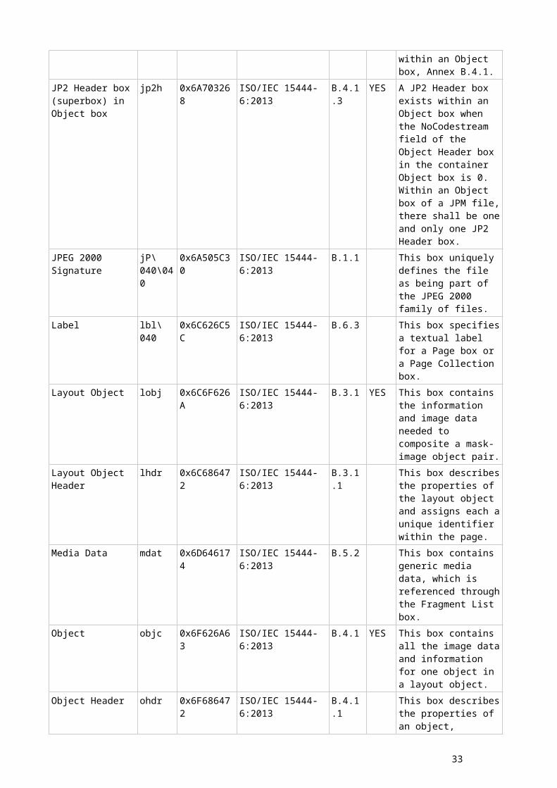
Specification Box
Base Non-linear Point Transformation Specification Box
LPTS 0x4C505453 ISO/IEC CD 18477-8
B.3
Residual Non-linear Point Transformation Specification Box
QPTS 0x51505453 ISO/IEC CD 18477-6
B.8. Defines how to transform data. Not toplevel.
Residual Non-linear Point Transformation Specification Box
QPTS 0x51505453 ISO/IEC CD 18477-8
B.4
Base Transformation Box
LTRF 0x4C545246 ISO/IEC CD 18477-6
B.9. Defines how to transform data. Not toplevel.
Base Transformation Box
LTRF 0x4C545246 ISO/IEC CD 18477-8
B.5
Residual Transformation Box
RTRF 0x52545246 ISO/IEC CD 18477-6
B.10. Defines how to transform data. Not toplevel.
Residual Transformation Box
RTRF 0x52545246 ISO/IEC CD 18477-8
B.6
Color Transformation Box
CTRF 0x43545246 ISO/IEC CD 18477-6
B.11 Defines how to transform data. Not toplevel.
Secondary Base Non-linear Point Transformation Box
CPTS 0x43505453 ISO/IEC CD 18477-7
B.3 Defines how to transform data.
Secondary Residual Non-linear Point Transformation Box
RPTS 0x52505453 ISO/IEC CD 18477-7
B.4 Defines how to transform data.
Prescaling Non-linear Point Transformation Box
SPTS 0x53505453 ISO/IEC CD 18477-7
B.5 Defines how to transform data. Not toplevel.
Postscaling Non-linear Point Transformation Box
PPTS 0x50505453 ISO/IEC CD 18477-7
B.6 Defines how to transform data. Not toplevel.
Prescaling Transformation Box
STRF 0x53545246 ISO/IEC CD 18477-7
B.7 Defines how to transform data. Not toplevel.
Residual Color DTRF 0x44545246 ISO/IEC CD B.8 Defines how to
33
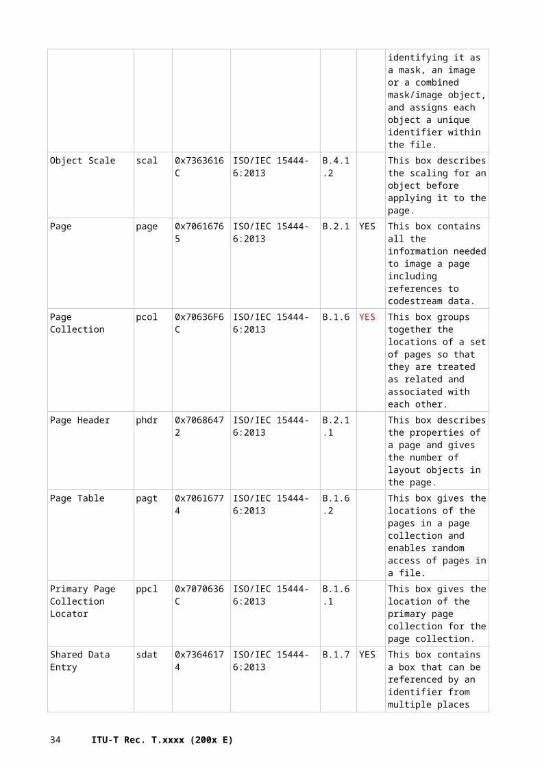
Transformation Box
18477-7 transform data. Not toplevel.
Intermediate Residual Non-linear Point Transformation Box
DPTS 0x44505453 ISO/IEC CD 18477-7
B.9 Defines how to transform data.
Base DCT Specification Box
LDCT 0x4C444354 ISO/IEC CD 18477-8
B.7 defines the DCT operation in the legacy decoding path
Residual DCT Specification Box
RDCT 0x52444354 ISO/IEC CD 18477-8
B.8 defines the DCT operation and the noise shaping in the residual decoding path
B.5.1 JPEG SearchBox name Type
(ASCII)Type (Hex) Containing
StandardAnnex/ Table/ Page
Comment/Description
UUID box (id 0x5135e9bb6f594f0c8b977b4765064994)
uuid 0x75756964 ISO/IEC 24800-4:2010
Section 6.3 (JPEG-2000 and its compliant file formats)
JPSearch Part 4 - File format - embedding in JPEG 2000 files - Each box contains one JPSearchMetadata block
B.5.1 JPEGBox name Type (ASCII) Type (Hex) Containing
StandardAnnex/ Table/ Page
Comment/Description
SPIFF Header 0xFFD8 FFE8 ISO/IEC 10918-3:1997
Table F.1 SPIFF Header Magic Number
B.6 Placement of BoxesThe File Type box must be placed as early as possible in the file (e.g. after any obligatory signature, but before any significant variable-size boxes such as a Movie Box, Media Data Box, or Free Space). It identifies which specification is the ‘best use’ of the file, and a minor version of that specification; and also a set of other specifications to which the file complies. Readers implementing this format should attempt to read files that are marked as compatible with any of the
34 ITU-T Rec. T.xxxx (200x E)
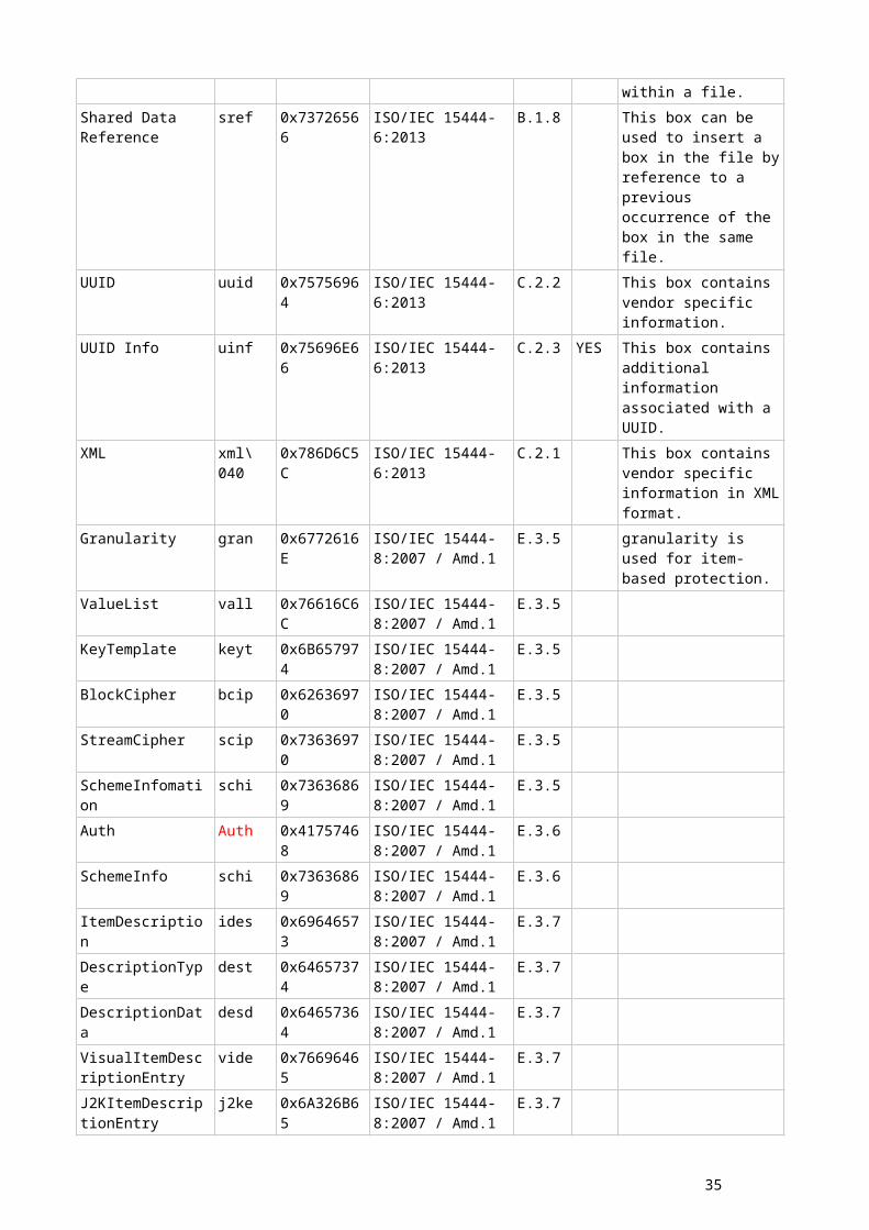
specifications that the reader implements. Any incompatible change in a specification should therefore register a new ‘brand’ identifier to identify files conformant to the new specification.
Some boxes shall be placed at the appropriate position in the contiguous sequence of boxes so that decoding process will be executed efficiently. Each box in a file does not represent that kind of mandatory or recommended rules but they should be described in the corresponding standard document. The rules for placement of boxes provide the following properties:
- uniqueness, all files shall contain one and only one box of a given type (e.g. File Type box defined in ISO/IEC 15444-1);
- head position, a box shall be the first box in the file or superbox (e.g. Image Header box defined in ISO/IEC 15444-1);
- medium position, a box shall be located anywhere between two boxes (e.g. JP2 Header box defined in ISO/IEC 15444-1);
- tail position, a box should be placed last in their superbox (e.g. User Data box defined in ISO/IEC 15444-12);
- neighboring, a box should be placed immediately after a specific box (e.g. Compound Image Header box defined in ISO/IEC 15444-6);
- nesting, a box that itself contains a contiguous sequence of boxes (and only a contiguous sequence of boxes), which is named superbox (e.g. Resolution box defined in ISO/IEC 15444-1);
- earliness, a box should be placed as early as possible in the file (e.g. Progressive Download Information box as defined in ISO/IEC 15444-12);
- absolute position, a box shall be placed in specific box (e.g. Codestream Registration box as defined in ISO/IEC 15444-2).
Please note that restricting the placement of boxes limits the efficiency and flexibility of the transport using for instance ISO/IEC 15444-9 (see also Annex B.3). Hence, placement constraints shall only be specified for well defined reasons.
35
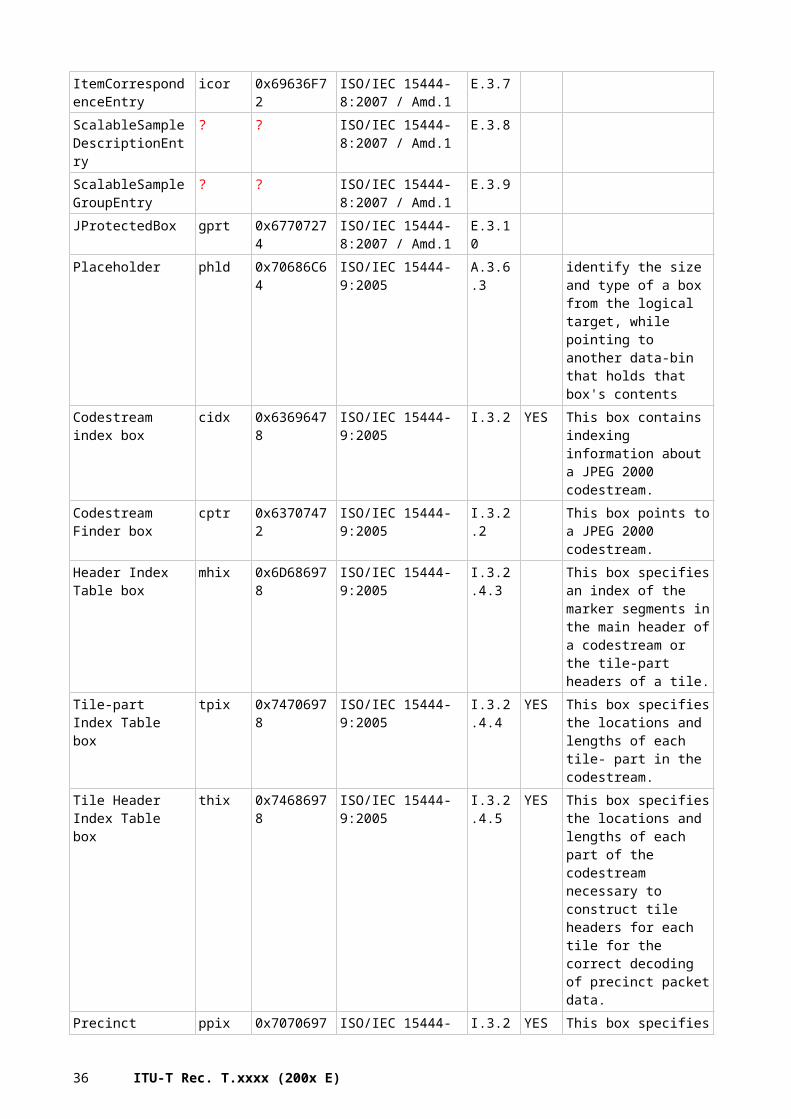
Annex C:Box-Based File Format Structure
(This annex forms an integral part of this Recommendation | International Standard)
C.1 IntroductionThis annex illustrates how file formats can be built from individual boxes as described in Annex B.
C.2 Boxed-base file format syntaxThe binary structure of a file is a contiguous sequence of boxes. Some of those boxes are independent, and some of those boxes contain other boxes. The start of the first box shall be the first byte of the file, and the last byte of the last box shall be the last byte of the file. The binary structure of a box is defined in Annex B.2.
C.3 Overview about existing file formatsSeveral file formats haven been defined in the past relying on the box format as illustrated inFigure C.1:
The compound image file format in ISO/IEC 15444-6:2013
The JP2 file format in ISO/IEC 15444-1:2004, Annex I
The JPX file format extended metadata definition and syntax in ISO/IEC 15444-2:2004, ISO/IEC 15444-2:2004/FDAM 3
The Motion JPEG MJ2 file format defined in ISO/IEC 15444-3:2007, ISO/IEC 15444-3:2007/Amd.1:2010
Figure C.1: JPEG box-based file formats
All of them base on the ISO base media file format and define particular semantics.
C.4 Example File Format Structure (Informative only)In order to guide the definition of future file formats, Figure C.2 shows the structure of a JP2 file. Boxes with dashed borders are optional in conforming JP2 files. However, an optional box may define mandatory boxes within that optional box. In that case, if the optional box exists, those mandatory boxes within the optional box shall exist. If the optional box does not exist, then the mandatory boxes within those boxes shall also not exist.
36 ITU-T Rec. T.xxxx (200x E)
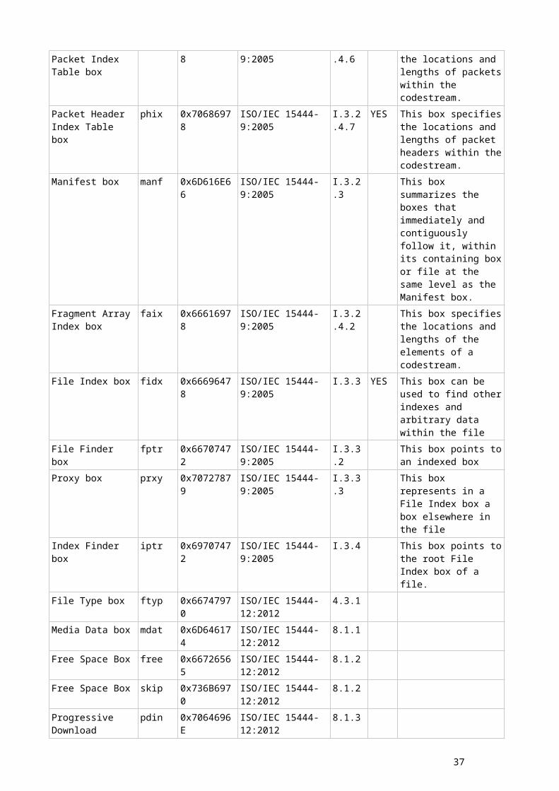
T.800_FI.1
JP2 file
JP2 Header box (superbox) (I.5.3)
Contiguous Codestream box (I.5.4) 0
Image Header box (I.5.3.1)
Colour Specification box 0 (I.5.3.3)
Bits Per Component box (I.5.3.2)
IPR box (I.6)
JPEG 2000 Signature box (I.5.1)
Channel Definition box (I.5.3.6)
XML boxes (I.7.1)
Colour Specification box n – 1 ( I.5.3.3)
UUID Info boxes (superbox) (I.7.3)
UUID List box (I.7.3.1)
Data Entry URL box (I.7.3.2)
UUID boxes (I.7.2)
Resolution box (superbox) (I.5.3.7)
Capture Resolution box (I.5.3.7.1)
Default Display Resolution box (I.5.3.7.2)
Palette box (I.5.3.4)
Contiguous Codestream box (I.5.4) m – 1
File Type box (I.5.2)
Component Mapping box (I.5.3.5)
Figure C.2 – Conceptual structure of a JP2 file (References point to ISO/IEC 15444-1:2004, Annex I)
Figure C.2 specifies only the containment relationship between the boxes in the file. A particular order of those boxes in the file is not generally implied. However, the JPEG 2000 Signature box shall be the first box in a JP2 file, the File Type box shall immediately follow the JPEG 2000 Signature box and the JP2 Header box shall fall before the Contiguous Codestream box.
The file shown in Figure C.2 is a sequence of boxes. Other boxes may be found between the boxes defined in ISO/IEC 15444-1:2004, Annex I. However, all information contained within a JP2 file shall be in the box format; byte-streams not in the box format shall not be found in the file.
As shown in Figure C.2, a JP2 file contains a JPEG 2000 Signature box, JP2 Header box, and one or more Contiguous Codestream boxes. A JP2 file may also contain other boxes as determined by the file writer. For example, a JP2 file may contain several XML boxes (containing metadata) between the JP2 Header box and the first Contiguous Codestream box.
37
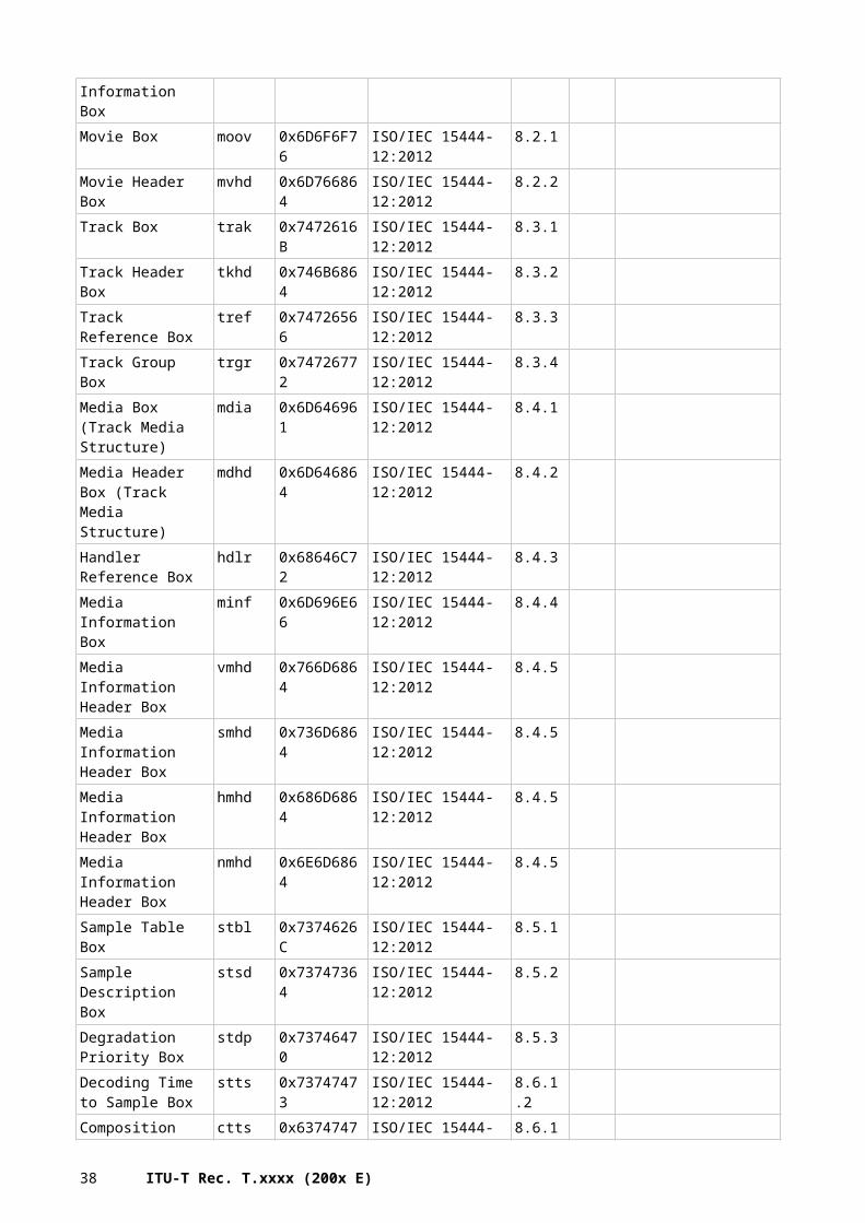
Annex D:Codestream Syntax
(This annex forms an integral part of this Recommendation | International Standard)
D.1 IntroductionWhile the box structure defined in Annex B is very powerful and flexible, it comes along with a certain overhead. Furthermore, it is not possible to just insert them into a bit stream of data for special signalling. Solving these aspects is the purpose of the markers.
Markers enable signalling of data that is relevant for decoding of the associated bit stream content. Additionally, markers serve as synchronisation points to facilitate features, such as error detection, error correction and random access functionality. Markers that embody extra information are called marker segments. A bit stream annotated with markers and marker segments is called a codestream.
This annex specifies a unified marker and marker segment syntax that is designed to be used in future specifications that include this Recommendation | International Standard as a normative reference.
This Recommendation | International Standard does not include a definition of compliance or conformance. The parameter values of the syntax described in this annex are not intended to portray the capabilities required to be compliant.
D.2 Markers, marker segments, and headersThis Recommendation | International Standard summarizes the mechanism of markers and marker segments to delimit and signal information contained in a codestream. The general marker syntax is defined in Rec. ITU-T T.81 | ISO/IEC 10918-1.Headers are collections of markers and marker segments.
Every marker is two bytes long. The first byte consists of a single 0xFF byte. The second byte denotes the specific marker code and can have any value in the range 0x01 to 0xFE.
A marker segment includes a marker and associated parameters, called marker segment fields. Every marker segment shall have a length field, that consists of two bytes following the marker. The length field is a big-endian unsigned integer value that denotes the size in bytes of all the marker segment fields (including the two bytes of this length parameter but excluding the two bytes of the marker itself). Following this strict convention allows a decoder to discard unknown marker segments by making use of the length field.
D.2.1 Types of markers and marker segmentsSix types of markers and marker segments are used: delimiting, fixed information, functional, in-bit stream, pointer and informational. Delimiting markers and marker segments are used to frame subparts of the codestream, such as the main and tile-part headers and the bit-stream data of 15444-1. Fixed information marker segments give required information about the image. The location of these marker segments, like delimiting marker and marker segments, is specified. Functional marker segments are used to describe the coding functions used. In-bit-stream markers and marker segments are used for error resilience. Pointer marker segments provide specific offsets in the bit stream. Informational marker segments provide ancillary information.
D.2.2 Marker RangesDifferent markers are defined in a variety of ISO/IEC JTC1 SC29 WG1 standards. The marker range 0xFF30 to 0xFF3F is reserved by this Recommendation | International Standard for markers without marker segment parameters. Table D.1 shows in which specification these markers and marker segments are defined.
38 ITU-T Rec. T.xxxx (200x E)
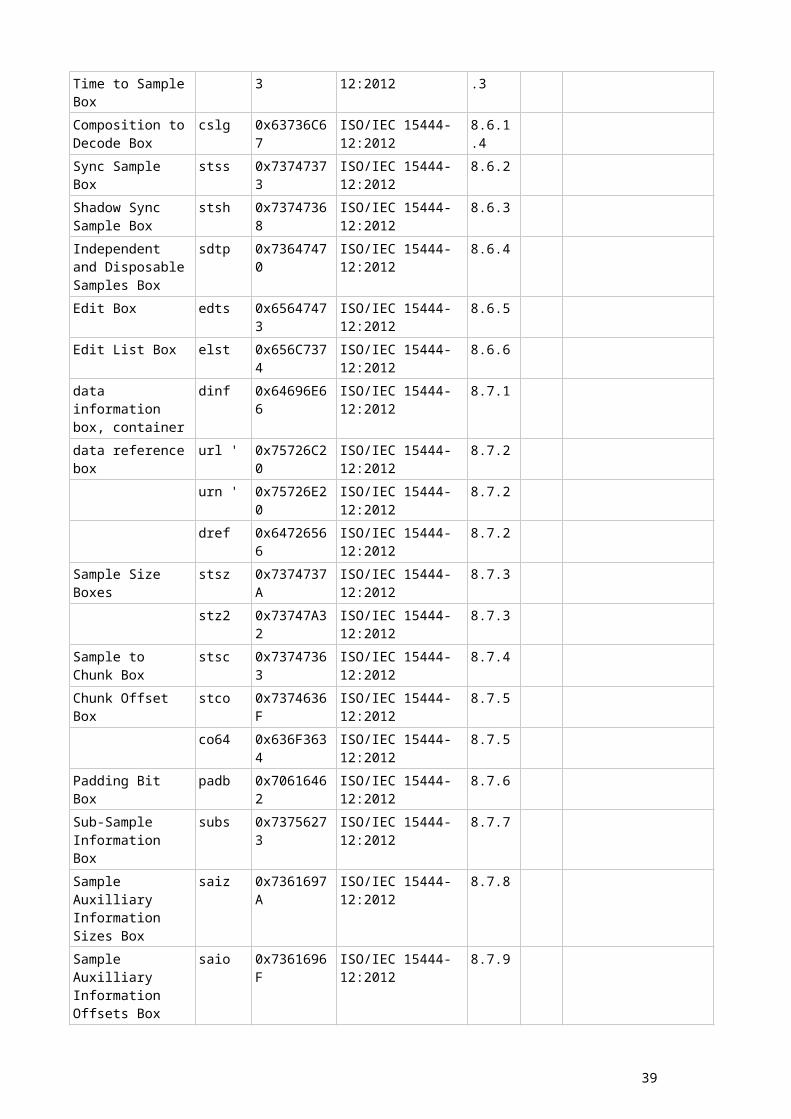
Table D.1 – Marker definitions
Marker code range Standard definition
0xFF00, 0xFF01, 0xFFFE, 0xFFC0 to 0xFFDF Defined in Rec. ITU-T T.81 | ISO/IEC 10918-10xFFF0 to 0xFFF6 Defined in Rec. ITU-T T.84 | ISO/IEC 10918-30xFFF7 to 0xFFF8 Defined in Rec. ITU-T T.87 | ISO/IEC 14495-10xFF4F to 0xFF6F, 0xFF90 to 0xFF93 Defined in ISO/IEC 15444-x family0xFF30 to 0xFF3F Reserved for definition as markers only (no marker segments)
All other values reserved
D.2.3 Marker and marker segment and codestream rules– Marker segments, and therefore also headers, are a multiple of 8 bits (one byte). Furthermore, the bit stream data
between the headers and before the EOC marker or end of file are padded (with zero bits) for 8-bit alignment.– Delimiting and fixed information marker and marker segments must appear at specific points in the codestream.
– The marker segments shall correctly describe the image as represented by the codestream. If truncation, alteration or editing of the codestream has been performed, the marker segments shall be updated, if necessary.
– All parameter values in marker segments shall be encoded big-endian.
– Marker segments can appear in any order in a given header, unless explicitly defined otherwise.
– All markers with the marker code between 0xFF30 and 0xFF3F have no marker segment parameters.
– Some marker segments have values assigned to groups of bits within a parameter. In some cases there are bits, denoted by "x," that are not assigned a value for any field within a parameter. The codestream shall contain a value of zero for all such bits. The decoder shall ignore these bits.
D.2.4 Bit-stuffing and byte-stuffing in contentAs specified, markers can be recognized by the 0xFFxx format. To facilitate synchronization and error correction in codestreams, two mechanisms, bit stuffing and byte stuffing, were designed to prevent sequences of two bytes from occurring in the range of 0xFF80 – 0xFFFF in a codestream. This allows a decoder to search forward for markers that fall within the 0xFF80 – 0xFFFF range.
D.2.4.1 Bit stuffing
Content bits in a codestream are packed into bytes from the MSB to the LSB. When the value of the byte is 0xFF, the next byte shall include an extra zero bit stuffed into the MSB. This guarantees that the content of a code-stream will never contain a sequence of two bytes in the range of 0xFF80 – 0xFFFF. The last byte in a sequence shall be padded to the 8-bit boundary with zero bits. Moreover, the last byte in the codestream shall not be a 0xFF value (thus the single zero bit stuffed after a byte with 0xFF must be included even if the 0xFF would otherwise have been the last byte).
D.2.4.2 Byte stuffing
Byte stuffing works identical to bit stuffing but uses a full zero byte after every 0xFF byte. This mechanism is only used in ISO 10918 (JPEG) and should no longer be used in newer standards, because it unnecessarily wastes 7 bits.
D.2.5 Graphical descriptions of markers (informative)Each marker segment is described in terms of its function, usage and length. The function describes the information contained in the marker segment. The usage describes the logical location and frequency of this marker segment in the codestream. The length describes which parameters determine the length of the marker segment.
These descriptions are followed by a figure that shows the order and relationship of the parameters in the marker segment. Figure D.1 shows an example of this type of figure. The marker segments are designated by the three-letter code of the marker associated with the marker segment. The parameter symbols have capital letter designations followed by the marker's symbol in lower-case letters. A rectangle is used to indicate a parameter's location in the marker segment. The width of the rectangle is proportional to the number of bytes of the parameter. A shaded rectangle (diagonal stripes) indicates that the parameter is of varying size. Two parameters with superscripts and a grey area between them indicate a run of several of these parameters.
39
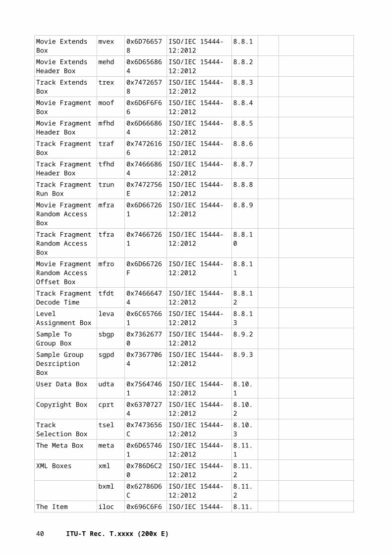
T.800_FA-1
16-bit marker8-bit parameter
32-bit parameter Run of n parameters
MAR
Dmar
Lmar
Am
ar
Bmar Cmar Emar1 Emarn
Variable-size parameter
Figure D.1 – Example of the marker segment description figures
The figure is followed by a list that describes the meaning of each parameter in the marker segment. If parameters are repeated, the length and nature of the run of parameters is defined. As an example, in Figure D.1, the first rectangle represents the marker with the symbol MAR. The second rectangle represents the length parameter. Parameters Amar, Bmar, Cmar, and Dmar are 8-, 16-, 32-bit and variable length respectively. The notation Emar i implies that there are n different parameters, Emari, in a row.
A table is given following the list of parameters that either describes the allowed parameter values or provides references to other tables that describe these values. Tables for individual parameters are provided to describe any parameter without a simple numerical value. In some cases these parameters are described by a bit value in a bit field. In this case, an "x" is used to denote bits that are not included in the specification of the parameter or sub-parameter in the corresponding row of the table.
Some marker segment parameters are described using the notation "Sxxx" and "SPxxx" (for a marker symbol, XXX). The Sxxx parameter selects between many possible states of the SPxxx parameter. According to this selection, the SPxxx parameter or parameter list is modified.
40 ITU-T Rec. T.xxxx (200x E)
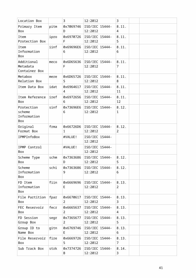
D.3 Markers in use This section provides the list of markers in use in known specifications.
D.3.1 ISO/IEC 15444-x family
Marker code
Marker symbol
Marker description Comment Containing Standard Annex/Table/Page
0xFF4F SOC Start of codestream Delimiting markers and marker segments
ISO/IEC 15444-1:2002 Table A.2
0xFF50 CAP Extended capabilities Extended marker segments ISO/IEC 15444-2:2004 / AMD2
Table A.49
0xFF51 SIZ Image and tile size Fixed information marker segments
ISO/IEC 15444-1:2002 Table A.2
0xFF52 COD Coding style default Functional marker segments ISO/IEC 15444-1:2002 Table A.2
0xFF53 COC Coding style component Functional marker segments ISO/IEC 15444-1:2002 Table A.2
0xFF54 NSI Additional dimension image and tile size
JP3D ISO/IEC 15444-10:2008
Table A.1
0xFF55 TLM Packed packet headers, tile-part header
Pointer marker segments ISO/IEC 15444-1:2002 Table A.2
0xFF57 PLM Tile-part lengths Pointer marker segments ISO/IEC 15444-1:2002 Table A.2
0xFF58 PLT Packet length, main header Pointer marker segments ISO/IEC 15444-1:2002 Table A.2
0xFF5A QPD Quantization default, precinct Extended marker segments ISO/IEC 15444-2:2002 Table A.19
0xFF5B QPC Quantization component, precinct
Extended marker segments ISO/IEC 15444-2:2002 Table A.19
0xFF5C QCD Quantization default Functional marker segments ISO/IEC 15444-1:2002 Table A.2
0xFF5D QCC Quantization component Functional marker segments ISO/IEC 15444-1:2002 Table A.2
0xFF5E RGN Region-of-interest Functional marker segments ISO/IEC 15444-1:2002 Table A.2
0xFF5F POC Progression order change Functional marker segments ISO/IEC 15444-1:2002 Table A.2
0xFF60 PPM Packet length, tile-part header Pointer marker segments ISO/IEC 15444-1:2002 Table A.2
0xFF61 PPT Packed packet headers, main header
Pointer marker segments ISO/IEC 15444-1:2002 Table A.2
0xFF63 CRG Component registration Informational marker segments ISO/IEC 15444-1:2002 Table A.2
0xFF64 COM Comment Informational marker segments ISO/IEC 15444-1:2002 Table A.2
0xFF65 SEC Main security marker the description of all required information for securing JPEG 2000 images
ISO/IEC 15444-8:2007 5.5
0xFF66 EPB Error Protection Block JPWL ISO/IEC 15444-11 Table A.2
0xFF67 ESD Error Sensitivity Descriptor JPWL ISO/IEC 15444-11 Table A.2
0xFF68 EPC Error Protection Capability JPWL ISO/IEC 15444-11 Table A.20xFF69 RED Residual Errors Descriptor JPWL ISO/IEC 15444-11 Table A.20xFF70 DCO Variable DC offset Extended marker segments ISO/IEC 15444-2:2002 Table A.190xFF71 VMS Visual masking Extended marker segments ISO/IEC 15444-2:2002 Table A.190xFF72 DFS Downsampling factor style Extended marker segments ISO/IEC 15444-2:2002 Table A.190xFF73 ADS Arbitrary decomposition style Extended marker segments ISO/IEC 15444-2:2002 Table A.190xFF74 MCT Multiple component
transformation definitionExtended marker segments ISO/IEC 15444-2:2002 Table A.19
0xFF75 MCC Multiple component collection Extended marker segments ISO/IEC 15444-2:2002 Table A.190xFF76 NLT Non-linearity point
transformationExtended marker segments ISO/IEC 15444-2:2002 Table A.19
0xFF77 MCO Multiple component transformation ordering
Extended marker segments ISO/IEC 15444-2:2002 Table A.19
0xFF77 MIC Multiple component intermediate collection
Extended marker segments ISO/IEC 15444-2:2002 / AMD1
Table A.17
0xFF78 CBD Component bit depth Extended marker segments ISO/IEC 15444-2:2002 Table A.190xFF79 ATK Arbitrary transformation
kernelsExtended marker segments ISO/IEC 15444-2:2002 Table A.19
0xFF90 SOT Start of tile-part Delimiting markers and marker segments
ISO/IEC 15444-1:2002 Table A.2
41
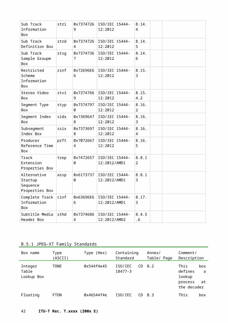
0xFF91 SOP Start of packet In-bit-stream markers and marker segments
ISO/IEC 15444-1:2002 Table A.2
0xFF92 EPH End of packet header In-bit-stream markers and marker segments
ISO/IEC 15444-1:2002 Table A.2
0xFF93 SOD Start of data Delimiting markers and marker segments
ISO/IEC 15444-1:2002 Table A.2
0xFF94 INSEC In-codestream security marker gives overall information about the JPSEC tools applied to protect the image.
ISO/IEC 15444-8:2007 5.13
0xFFD9 EOC End of codestream Delimiting markers and marker segments
ISO/IEC 15444-1:2002 Table A.2
D3.2 JPEG-XT familyMarker code
Marker symbol
Marker description Comment Containing Standard Annex Table/Page
0xFFB1 SOFr1 Sequential DCT bypass Start of Frame markers ISO/IEC 18477-8 Table D.1
0xFFB2 SOFr2 Progressive DCT bypass Start of Frame markers ISO/IEC 18477.8 Table D.1
0xFFB3 SOFe1 Sequential large range process Start of Frame markers ISO/IEC 18477.8 Table D.1
0xFFB9 SOFr3 reserved for Sequential AC-coded DCT bypass
Start of Frame markers ISO/IEC 18477.8 Table D.1
0xFFBA SOFr4 reserved for Progressive AC-coded DCT bypass
Start of Frame markers ISO/IEC 18477.8 Table D.1
0xFFC0 SOF0 Baseline DCT Process Start of Frame markers ISO/IEC 18477-1 Table B.1
0xFFC1 SOF1 Extended Sequential DCT Process limited to 8 bit sample precision (extended sequential, Huffman coding, 8-bit sample precision)
Start of Frame markers ISO/IEC 18477-1 Table B.1
0xFFC2 SOF2 Progressive DCT Process limited to 8 bit sample precision (spectral selection only, Huffman coding, 8-bit sample precision or full progression, Huffman coding, 8-bit sample precision)
Start of Frame markers ISO/IEC 18477-1 Table B.1
0xFFC3 SOF3 Additional Start of Frame Markers, shall not be used.
Start of Frame markers ISO/IEC 18477-1 Table B.1
0xFFC5 SOF5 Additional Start of Frame Markers, shall not be used.
Start of Frame markers ISO/IEC 18477-1 Table B.1
0xFFC6 SOF6 Additional Start of Frame Markers, shall not be used.
Start of Frame markers ISO/IEC 18477-1 Table B.1
0xFFC7 SOF7 Additional Start of Frame Markers, shall not be used.
Start of Frame markers ISO/IEC 18477-1 Table B.1
0xFFC9 SOF9 Additional Start of Frame Markers, shall not be used.
Start of Frame markers ISO/IEC 18477-1 Table B.1
0xFFCA SOF10 Additional Start of Frame Markers, shall not be used.
Start of Frame markers ISO/IEC 18477-1 Table B.1
0xFFCB SOF11 Additional Start of Frame Markers, shall not be used.
Start of Frame markers ISO/IEC 18477-1 Table B.1
0xFFCD SOF12 Additional Start of Frame Markers, shall not be used.
Start of Frame markers ISO/IEC 18477-1 Table B.1
0xFFCE SOF14 Additional Start of Frame Markers, shall not be used.
Start of Frame markers ISO/IEC 18477-1 Table B.1
0xFFCF SOF15 Additional Start of Frame Markers, shall not be used.
Start of Frame markers ISO/IEC 18477-1 Table B.1
0xFFC4 DHT Define Huffman Tables Table Specifications ISO/IEC 18477-1 Table B.1
0xFFDB DQT Define Quantization Tables Table Specifications ISO/IEC 18477-1 Table B.1
0xFFD0-0xFFD7
RSTm Restart modulo 8 count 'm' Restart Interval Termination ISO/IEC 18477-1 Table B.1
0xFFDD DRI Define Restart Interval Restart Interval Termination ISO/IEC 18477-1 Table B.1
42 ITU-T Rec. T.xxxx (200x E)
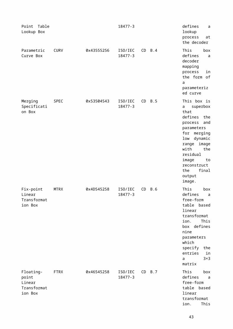
0xFFD8 SOI Start of Image Other Markers ISO/IEC 18477-1 Table B.1
0xFFD9 EOI End of Image Other Markers ISO/IEC 18477-1 Table B.1
0xFFDA SOS Start of Scan Other Markers ISO/IEC 18477-1 Table B.1
0xFFFE COM Comment Other Markers ISO/IEC 18477-1 Table B.1
0xFFE0 APP0 JFIF Application Marker JPEG Extension Markers ISO/IEC 18477-1 Table B.1
0xFFE1 APP1 EXIF Application Marker JPEG Extension Markers ISO/IEC 18477-1 Table B.1
0xFFE2 APP2 ICC Profile Marker JPEG Extension Markers ISO/IEC 18477-1 Table B.1
0xFFE3-0xFFEA
APP3-APP10
JPEG Extension Markers ISO/IEC 18477-1 Table B.1
0xFFEB APP11 JPEG XT Marker JPEG Extension Markers ISO/IEC 18477-1 Table B.1
0xFFEC APP12 Application Marker 12 JPEG Extension Markers ISO/IEC 18477-1 Table B.1
0xFFED APP13 Component Decorrelation Control Marker
JPEG Extension Markers ISO/IEC 18477-1 Table B.1
0xFFEE APP14 Application Marker 14 JPEG Extension Markers ISO/IEC 18477-1 Table B.1
0xFFEF APP15 Application Marker 15 JPEG Extension Markers ISO/IEC 18477-1 Table B.1
0xFFC8 JPG Reserved for JPEG Extensions Markers defined in other specifications that shall not be used in this Recommendation | International Standard
ISO/IEC 18477-1 Table B.1
0xFFCC DAC Define Arithmetic Coding Conditions
Markers defined in other specifications that shall not be used in this Recommendation | International Standard
ISO/IEC 18477-1 Table B.1
0xFFDC DNL Define Number of Lines Markers defined in other specifications that shall not be used in this Recommendation | International Standard
ISO/IEC 18477-1 Table B.1
0xFFDE DHP Define Hierarchical Progression Markers defined in other specifications that shall not be used in this Recommendation | International Standard
ISO/IEC 18477-1 Table B.1
0xFFDF EXP Expand Reference Components Markers defined in other specifications that shall not be used in this Recommendation | International Standard
ISO/IEC 18477-1 Table B.1
0xFFEB APP11 DD Carriage of residual data and parameters
ISO/IEC 18477-2 Section 7
0xFFEB APP11 JP (0x4A50) Carriage marker of boxes ISO/IEC 18477-3 Annex A.2ff
43
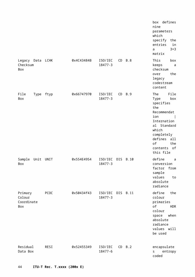
D3.3 JPEG Search
Marker code
Marker symbol
Marker description Comment Containing Standard Annex Table/Page
0xFFE3 APP3 JPSearch Part 4 - File format - embedding in JPEG files - Each segment contains one JPSearchMetadata block
ISO/IEC 24800-4:2010 Section 6.2 (JPEG-1 and its compliant file formats)
D3.4 JPEG
Marker code
Marker symbol
Marker description Comment Containing Standard Annex Table/Page
0xFFC0 SOF0 Baseline DCT Start Of Frame markers, non-differential, Huffman coding
ISO/IEC 10918-1 : 1993
Table B.1
0xFFC1 SOF1 Extended sequential DCT Start Of Frame markers, non-differential, Huffman coding
ISO/IEC 10918-1 : 1993
Table B.1
0xFFC2 SOF2 Progressive DCT Start Of Frame markers, non-differential, Huffman coding
ISO/IEC 10918-1 : 1993
Table B.1
0xFFC3 SOF3 Lossless (sequential) Start Of Frame markers, non-differential, Huffman coding
ISO/IEC 10918-1 : 1993
Table B.1
0xFFC5 SOF5 Differential sequential DCT Start Of Frame markers, differential, Huffman coding
ISO/IEC 10918-1 : 1993
Table B.1
0xFFC6 SOF6 Differential progressive DCT Start Of Frame markers, differential, Huffman coding
ISO/IEC 10918-1 : 1993
Table B.1
0xFFC7 SOF7 Differential lossless (sequential) Start Of Frame markers, differential, Huffman coding
ISO/IEC 10918-1 : 1993
Table B.1
0xFFC8 JPG Reserved for JPEG extensions Start Of Frame markers, non-differential, arithmetic coding
ISO/IEC 10918-1 : 1993
Table B.1
0xFFC9 SOF9 Extended sequential DCT Start Of Frame markers, non-differential, arithmetic coding
ISO/IEC 10918-1 : 1993
Table B.1
0xFFCA
SOF10 Progressive DCT Start Of Frame markers, non-differential, arithmetic coding
ISO/IEC 10918-1 : 1993
Table B.1
0xFFCB SOF11 Lossless (sequential) Start Of Frame markers, non-differential, arithmetic coding
ISO/IEC 10918-1 : 1993
Table B.1
0xFFCD
SOF13 Differential sequential DCT Start Of Frame markers, differential, arithmetic coding
ISO/IEC 10918-1 : 1993
Table B.1
0xFFCE SOF14 Differential progressive DCT Start Of Frame markers, differential, arithmetic coding
ISO/IEC 10918-1 : 1993
Table B.1
0xFFCF SOF15 Differential lossless (sequential) Start Of Frame markers, differential, arithmetic coding
ISO/IEC 10918-1 : 1993
Table B.1
0xFFC4 DHT Define Huffman table(s) Huffman table specification ISO/IEC 10918-1 : 1993
Table B.1
0xFFCC DAC Define arithmetic coding conditioning(s)
Arithmetic coding conditioning specification
ISO/IEC 10918-1 : 1993
Table B.1
0xFFD0-0xFFD7
RSTm Restart with modulo 8 count “m” Restart interval termination ISO/IEC 10918-1 : 1993
Table B.1
0xFFD8 SOI Start of image Other markers ISO/IEC 10918-1 : 1993
Table B.1
0xFFD9 EOI End of image Other markers ISO/IEC 10918-1 : 1993
Table B.1
0xFFDA
SOS Start of scan Other markers ISO/IEC 10918-1 : 1993
Table B.1
0xFFDB
DQT Define quantization table(s) Other markers ISO/IEC 10918-1 : 1993
Table B.1
44 ITU-T Rec. T.xxxx (200x E)
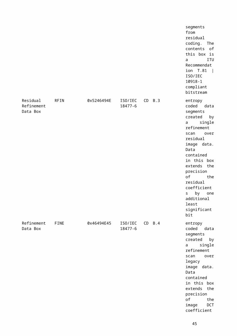
0xFFDC
DNL Define number of lines Other markers ISO/IEC 10918-1 : 1993
Table B.1
0xFFDD
DRI Define restart interval Other markers ISO/IEC 10918-1 : 1993
Table B.1
0xFFDE DHP Define hierarchical progression Other markers ISO/IEC 10918-1 : 1993
Table B.1
0xFFDF EXP Expand reference component(s) Other markers ISO/IEC 10918-1 : 1993
Table B.1
0xFFE0-0xFFEF
APPn Reserved for application segments Other markers ISO/IEC 10918-1 : 1993
Table B.1
0xFFF0-0xFFFD
JPGn Reserved for JPEG extensions Other markers ISO/IEC 10918-1 : 1993
Table B.1
0xFFFE COM Comment Other markers ISO/IEC 10918-1 : 1993
Table B.1
0xFF01 TEM For temporary private use in arithmetic coding
Other markers ISO/IEC 10918-1 : 1993
Table B.1
0xFF02-0xFFBF
RES Reserved Other markers ISO/IEC 10918-1 : 1993
Table B.1
0xFFF0 VER Version Version 1 extensions ISO/IEC 10918-3 : 1996
Table B.1
0xFFF1 DTI Define tiled image Version 1 extensions ISO/IEC 10918-3 : 1996
Table B.1
0xFFF2 DTT Define tile Version 1 extensions ISO/IEC 10918-3 : 1996
Table B.1
0xFFF3 SRF Selectively refined frame Version 1 extensions ISO/IEC 10918-3 : 1996
Table B.1
0xFFF4 SRS Selectively refined scan Version 1 extensions ISO/IEC 10918-3 : 1996
Table B.1
0xFFF5 DCR Define component registration Version 1 extensions ISO/IEC 10918-3 : 1996
Table B.1
0xFFF6 DQS Define quantizer scale selection Version 1 extensions ISO/IEC 10918-3 : 1996
Table B.1
0xFFE8 EMN SPIFF Directory start/end Not a true marker ISO/IEC 10918-3 : 1996
Table F.2
0xFFE6 APP6 NITF application data marker NITF APP6 application data segment
ISO/IEC 10918-4 : 1998
Section B.1.1.9.1
0xFFE7 APP7 NITF directory segment marker NITF APP7 directory segments ISO/IEC 10918-4 : 1998
Section B.1.1.9.2
0xFFE0 APP0 JFIF JPEG File Interchange Format ISO/IEC 10918-4 : 1999 AMD1
Table D.1
0xFFE0 APP0 JFXX Extended JFIF ISO/IEC 10918-4 : 1999 AMD1
Table D.1
0xFFE0 APP0 CIFF Camera Image File Format (used by some Canon models)
ISO/IEC 10918-4 : 1999 AMD1
Table D.1
0xFFE0 APP0 AVI1 JPEG AVI information ISO/IEC 10918-4 : 1999 AMD1
Table D.1
0xFFE1 APP1 EXIF Exchangeable Image File Format (including maker notes)
ISO/IEC 10918-4 : 1999 AMD1
Table D.1
0xFFE1 APP1 XMP Extensible Metadata Platform (multi-segment)
ISO/IEC 10918-4 : 1999 AMD1
Table D.1
0xFFE1 APP1 QVCI Casio QV-7000SX QVCI information
ISO/IEC 10918-4 : 1999 AMD1
Table D.1
0xFFE1 APP1 PIC Accusoft Pegasus custom fields ISO/IEC 10918-4 : 1999 AMD1
Table D.1
0xFFE2 APP2 ICC_PROFILE International Color Consortium (multi-segment)
ISO/IEC 10918-4 : 1999 AMD1
Table D.1
0xFFE2 APP2 FPXR FlashPix Ready (multi-segment) ISO/IEC 10918-4 : 1999 AMD1
Table D.1
45
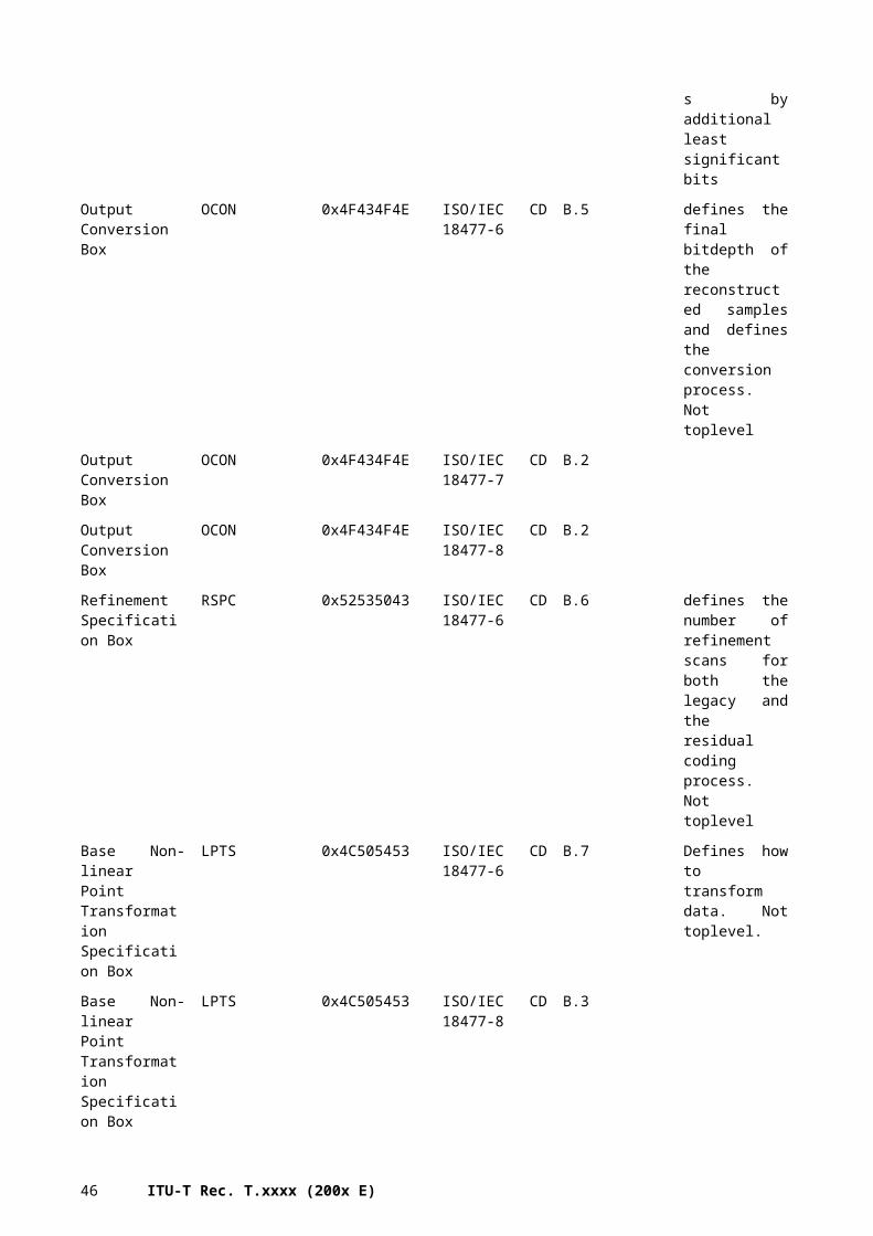
0xFFE2 APP2 MPF Multi-Picture Format ISO/IEC 10918-4 : 1999 AMD1
Table D.1
0xFFE2 APP2 PreviewImage Samsung large preview (multi-segment)
ISO/IEC 10918-4 : 1999 AMD1
Table D.1
0xFFE3 APP3 Kodak Meta Kodak Meta information (EXIF-like)
ISO/IEC 10918-4 : 1999 AMD1
Table D.1
0xFFE3 APP3 Stim Stereo Still Image format ISO/IEC 10918-4 : 1999 AMD1
Table D.1
0xFFE3 APP3 PreviewImage Hewlett-Packard or Samsung (multi-segment) preview
ISO/IEC 10918-4 : 1999 AMD1
Table D.1
0xFFE4 APP4 Scalado (presumably written by Scalado mobile software)
ISO/IEC 10918-4 : 1999 AMD1
Table D.1
0xFFE4 APP4 FPXR FlashPix Ready in non-standard location (multi-segment)
ISO/IEC 10918-4 : 1999 AMD1
Table D.1
0xFFE4 APP4 PreviewImage Continued Samsung preview from APP3
ISO/IEC 10918-4 : 1999 AMD1
Table D.1
0xFFE5 APP5 Ricoh RMETA Ricoh custom fields ISO/IEC 10918-4 : 1999 AMD1
Table D.1
0xFFE6 APP6 EPPIM Toshiba PrintIM ISO/IEC 10918-4 : 1999 AMD1
Table D.1
0xFFE6 APP6 NITF National Imagery Transmission Format
ISO/IEC 10918-4 : 1999 AMD1
Table D.1
0xFFE6 APP6 HP TDHD Hewlett-Packard Photosmart R837 TDHD information
ISO/IEC 10918-4 : 1999 AMD1
Table D.1
0xFFE7 APP7 NITF0003.A NIFT directory data segment ISO/IEC 10918-4 : 1999 AMD1
Table D.1
0xFFE8 APP8 SPIFF Still Picture Interchange File Format
ISO/IEC 10918-4 : 1999 AMD1
Table D.1
0xFFEA APP10 Comment PhotoStudio Unicode Comment ISO/IEC 10918-4 : 1999 AMD1
Table D.1
0xFFEB APP11 DD Still image extension ISO/IEC 10918-4 : 1999 AMD1
Table D.1
0xFFEC APP12 Picture Info ASCII-based Picture Information
ISO/IEC 10918-4 : 1999 AMD1
Table D.1
0xFFEC APP12 Ducky Photoshop "Save for Web" ISO/IEC 10918-4 : 1999 AMD1
Table D.1
0xFFED APP13 Photoshop IRB Image Resource Block (multi-segment, includes IPTC)
ISO/IEC 10918-4 : 1999 AMD1
Table D.1
0xFFED APP13 Adobe CM Adobe Color Management ISO/IEC 10918-4 : 1999 AMD1
Table D.1
0xFFEE APP14 Adobe Adobe DCT filter ISO/IEC 10918-4 : 1999 AMD1
Table D.1
0xFFEF APP15 GraphicConverter GraphicConverter quality ISO/IEC 10918-4 : 1999 AMD1
Table D.1
0xFFF7 SOF55 Start of frame JPEG-LS ISO/IEC 14495-1 : 1999
Section C.1.1
0xFFF8 LSE Preset parameters/extended functions JPEG-LS ISO/IEC 14495-1 : 1999
Section C.1.1
0xFFF9 SOF57 Start of frame JPEG-LS Extensions ISO/IEC 14495-2 : 2003
Section G.1.1
0xFFF8 LSE Preset parameters/extended functions JPEG-LS Extensions ISO/IEC 14495-2 : 2003
Section G.1.1
0xFF04 ABORT Abort ISO/IEC 11544:1993 Table 2
0xFF06 ATMOVE
AT movement ISO/IEC 11544:1993 Table 2
0xFF07 COMMENT
Private comment ISO/IEC 11544:1993 Table 2
0xFF05 NEWLEN New length ISO/IEC 11544:1993 Table 2
0xFF01 RESERV Reserve ISO/IEC 11544:1993 Table 2
46 ITU-T Rec. T.xxxx (200x E)

E0xFF02 SDNOR
MNormal stripe data end ISO/IEC 11544:1993 Table 2
0xFF03 SDRST Reset at stripe data end ISO/IEC 11544:1993 Table 2
0xFF00 STUFF Stuff ISO/IEC 11544:1993 Table 2
0xFFA8 (informative) starting marker ISO/IEC 11544 : 1993/Cor.1
6.2.1, NOTE
0xFFA9 (informative) ending marker ISO/IEC 11544 : 1993/Cor.1
6.2.1, NOTE
0xFFAA
starting marker ISO/IEC 14492 D.3
0xFFAB
ending marker ISO/IEC 14492 D.3
0xFFD8FFED
SOP Start of page marker segment ISO/IEC 16485 9.2.1
0xFFD9FFD9
EOP End of page marker segment ISO/IEC 16485 9.4
0xFFD9 TN Termination Number alert decoders to the end of the initial JPEG application markers
ISO/IEC 16485 9.2.3
0xFFED APP13 MRC uniquely identifies MRC ISO/IEC 16485 9.2
47
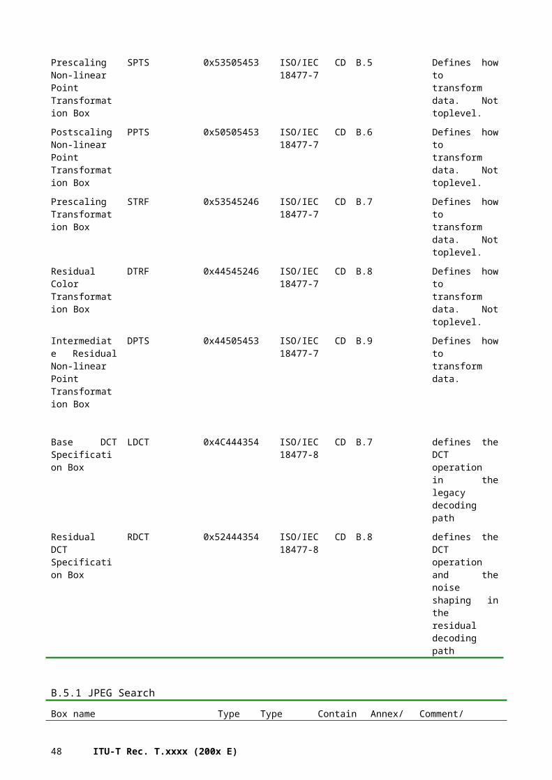
Annex E:Codec/Codestream Functionality Guidelines
(This Annex is informative only and is not an integral part of this Recommendation | International Standard)
E.1 IntroductionThis section describes some general functionalities/semantics of the compression codecs. These functionalities need to be exposed on the codestream level (and in same cases the file format level) in order to be properly usable.
E.2 Resolution ScalabilityResolution scalability is the ability of the decoder to extract a lower resolution of the image without request to decode or even read the complete encoded image file. By these means, computation and memory efforts can be limited, network bandwidth saved.
On the algorithmic level, various strategies exist to provide resolution scalability, such as pyramidal prediction or wavelet decomposition. In general, any spatial decorrelation transformation for energy compaction purposes that generates bands that represent approximately spatial scales of the image are suitable to realize resolution scalability.
On the syntactical level, the interface shall allow the client to spot the necessary data parts necessary to decode a desired resolution. In other words, it is necessary to spot the data whose decoding allows starting from an available resolution to compute the next larger resolution.
Resolution scalability can be realized both at the file format and the codestream level of an image format; it can be achieved by ordering the data according to the bands created by the decorrelation transformation, and packaging them into dedicated boxes. It is understood that this solution may increase the coding overhead and may not always desirable when optimal coding performance is desirable. In such a case, the file format may provide pointer mechanisms that point to the relevant pieces of information within the codestream, hence to enable the decoder to locate the necessary scales from the codestream.
E.3 Bit Depth ScalabilityIn order to cover the large illumination differences in natural images and computer generated scenes, luminance and color pixel values need to span a large numerical range. The necessary range is application dependent and may range from two bits (binary images, black and white) to 32 bits per sample or above. If the required dynamic range exceeds the range of integer samples, floating point representations become necessary. Some applications also require representation of negative numbers, for example to represent sample values that are outside of the gamut of the indicated color space. Bit depths scalablity manifests itself in the syntax of the codestream and file format, and the possible functionalities enabled by the format.
Syntactically, bit depth scalability describes the ability of an image format to represent images of a wide (contiguous) range of a bit depths, at least for integer samples, ideally also allowing the representation of floating point samples, by parametrizing the format according to the bit-depths.
As far as the functionalities are concerned, a bit-depth scalable format may enable decodes to extract a lower-bit depth variant from a high-bit depth (and/or high dynamic range) image represented by the image file, in particular to enable viewing on output devices that only support a lower bit-depths and/or lower dynamic range. Scaling, or equivalently, dropping least significant bits, may only be sufficient in very simple applications. It is often desirable to map the input luminance range to the target display using some form of tone mapping or clipping. While automatic algorithms for this task have been described in the literature, the mapping requires in most cases manual steering, representing thus a creative decision. If different target devices with different dynamic range capabilities need to be addressed, multiple versions of the content have to be provided.
Using completely separate files for this task is a straightforward solution, however, it issues problems with the content organization, as the different versions might get inconsistent. Moreover, the scheme how to organize the files is not standardized, complicating the access on the client side.
To solve these issues, two principle approaches are envisable. First of all, the different versions of the content can simply be packed as independent layers into one codestreams, possibly with different coding rules, as illustrated in Figure E.1. While this is straight forward, it might be inefficient in terms of storage space. Note that even different codestreams within one file might be used. This, however, causes that some of the meta data such as the image extensions are redundant and should hence be avoided.
48 ITU-T Rec. T.xxxx (200x E)
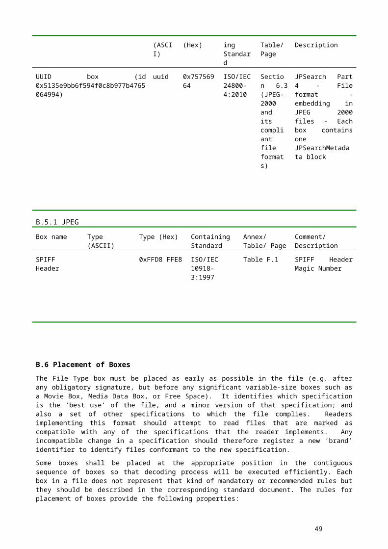
File
LDR layer
Coding rule AParams A
HDR layer
Coding rule BParams B
Figure E.1: Combination of different content versions into one file
Figure E.2 shows an alternative approach where multiple versions of the same content are described by means of a base layer and one or several extension layers that are placed within the same codestream or within the same file. The base layer can be decoded as it is, leading to a useful image representation. The extension layers provide the data necessary to translate the base layer image to an alternative higher precision or higher dynamic range representation. The rendering rules define how to combine the base layer with the extension layer to the final output image.
File
LDR Baselayer
Rendering rules
Coding rule AParams A
HDR Extension
Coding rule BParams B
Figure E.2: Coding of multiple image versions by a base layer and one or several enhancement layers.
Rendering algorithms are heavily dependent on the application and may be of very different nature. They can be as simple as indicating a global pixel-wise transformation, or may describe a region or content-dependent local mapping.
The definition of these mappings hence heavily depends on the use cases and is part of the individual standards.
E.4 Spatial ScalabilitySpatial scalability is the ability to extract and decode a geometric subregion of the image without needing to read the complete file.
Syntactically, spatial scalability can be realized on the codestream or file format level by providing access to image regions; a very simple mechanism to enable spatial scalability is to separate images into rectangular subregions, often called tiles, that are coded independently of each other. However, such a simple arrangement often compromises image quality due to coding artifacts at tile edges. Preferably, coder designs should avoid such artifacts, for example by separating the image in the transform domain, or by overlapping the tiles in the spatial domain. The former mechanism is used in JPEG 2000, there denoted as "precincts", the latter in JPEG XR and by some extensions of JPEG 2000.
As spatial scalability might be quite fine grained, it is typically handled at codestream level, ideally providing an easy-access mechanism at file format or codestream level that enables the decoder to skip over encoded image data that is not needed for a desired image region
E.5 Component ScalabilityIf the samples in the source image are of vectorial (rather than scalar) nature, image components represent the components of each of the components of the vectorial input. For example, the input data is in the form of (red,green,blue) triples relatively to a target colorspace, but other uses for vectorial data exist, e.g. multispectral satelite sensor data.
49
Component scalability is the ability of an image format to represent images independent of the number of components its vectorial input data may consist of. It requires a parametrized codestream and/or file format that enables the encoding of a varying number of components.
To optimize coding performance, image formats typically include decorrelation transformations between image components, even though such transformations may limit the ability of a decoder to extract individual components.
The syntax of a component-scalable file format enables a decoder to find and extract image components without enforcing it to decode the entire file and/or all of the components. Enough information must be provided to identify all image data necessary to reconstruct a desired component, for example including all the information necessary to identify all input data to run an inverse component decorrelation transformation for a desired output component or component subset. Such syntax could be realized, in the simplest case, by packaging components into individual boxes, at the file format level, or by including pointer information in the file format level to identify the codestream elements necessary for a desired target component.
50 ITU-T Rec. T.xxxx (200x E)