Embed Size (px)
Citation preview

ProLight PG1A-3LXE-XX3W Power LED Technical Datasheet
Version: 2.1
Features High Flux per LED Very long operating life(up to 100k hours) Available in White, Warm White, Green, Blue, Amber, Red-Orangeand Red Lambertian or Collimated Radiation Pattern More Energy Efficient than Incandescent and most Halogen lamps Low Voltage DC operated Cool beam, safe to the touch Instant light (less than 100ns) No UV Superior ESD protection Soldering methods: IR reflow soldering and Hand soldering
Typical Applications Reading lights (car, bus, aircraft) Portable (flashlight, bicycle) Decorative Appliance Sign and Channel Letter Architectural Detail Cove Lighting Automotive Exterior (Stop-Tail-Turn, CHMSL, Mirror Side Repeat) LCD backlight
1
Technology Corporation
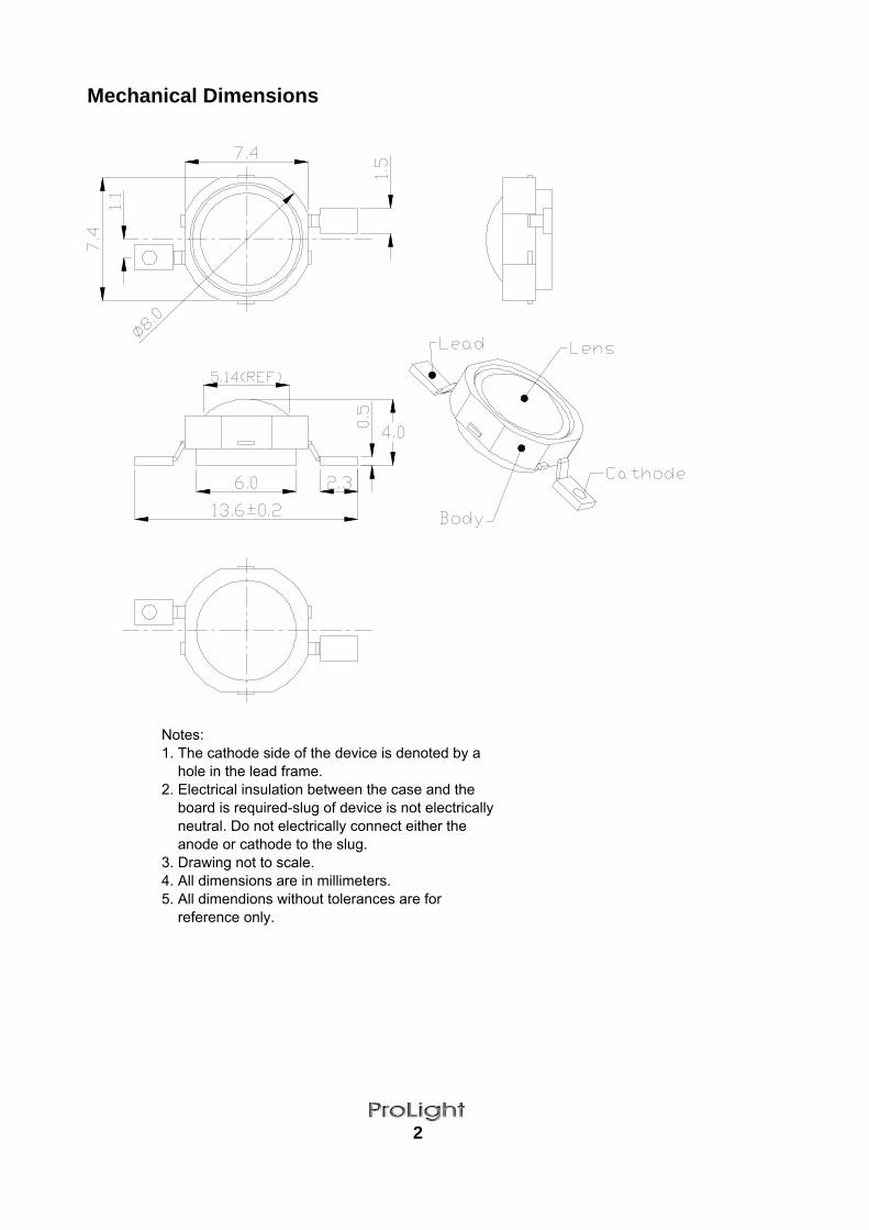
Mechanical Dimensions
2
Notes:1. The cathode side of the device is denoted by a hole in the lead frame.2. Electrical insulation between the case and the board is required-slug of device is not electrically neutral. Do not electrically connect either the anode or cathode to the slug.3. Drawing not to scale.4. All dimensions are in millimeters.5. All dimendions without tolerances are for reference only.
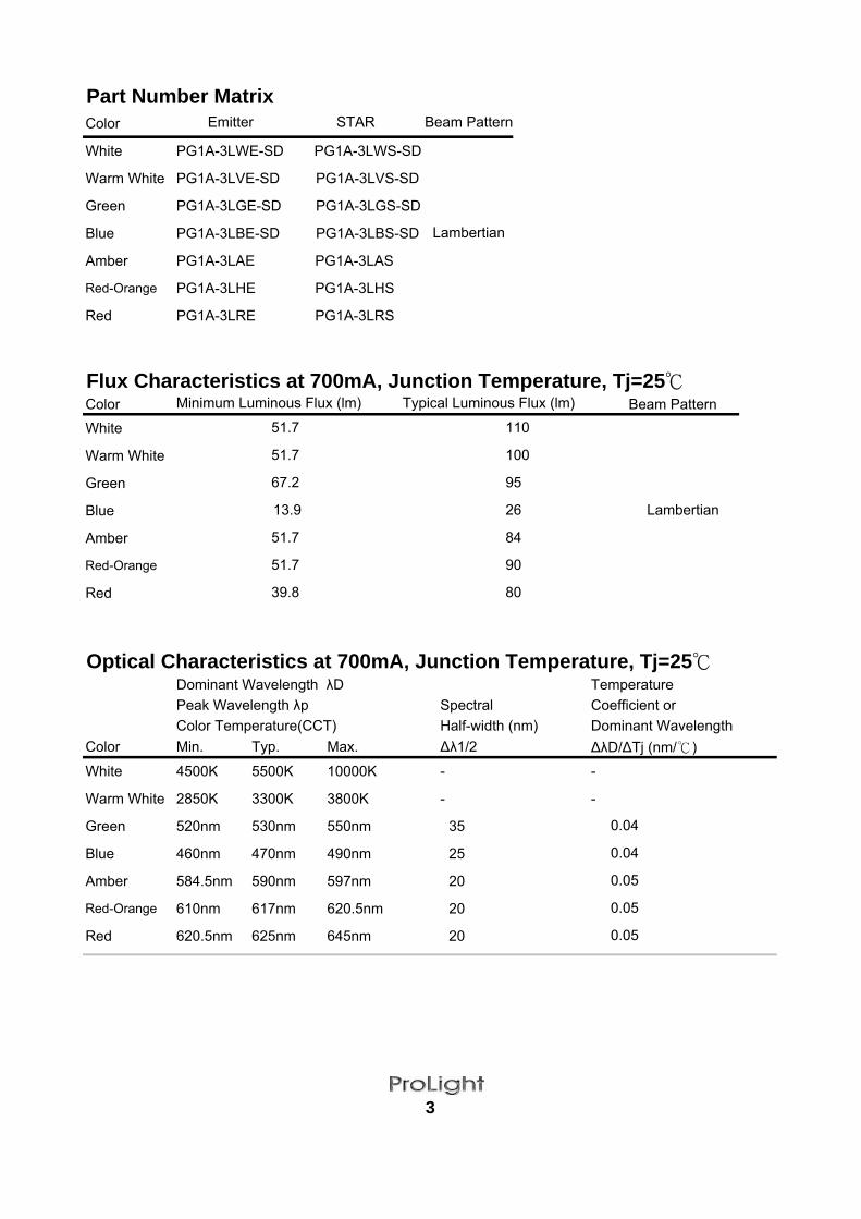
Part Number MatrixColor
White PG1A-3LWE-SD PG1A-3LWS-SD
Warm White PG1A-3LVE-SD PG1A-3LVS-SD
Green PG1A-3LGE-SD PG1A-3LGS-SD
Blue PG1A-3LBE-SD PG1A-3LBS-SD
Amber PG1A-3LAE PG1A-3LAS
Red-Orange PG1A-3LHE PG1A-3LHS
Red PG1A-3LRE PG1A-3LRS
Flux Characteristics at 700mA, Junction Temperature, Tj=25Color Beam PatternWhite
Warm White
Green
Blue
Amber
Red-Orange
Red
Optical Characteristics at 700mA, Junction Temperature, Tj=25Dominant Wavelength λD TemperaturePeak Wavelength λp Spectral Coefficient orColor Temperature(CCT) Half-width (nm) Dominant Wavelength
Color Min. Typ. Max. ∆λ1/2 ∆λD/∆Tj (nm/)White 4500K 5500K 10000K - -
Warm White 2850K 3300K 3800K - -
Green 520nm 530nm 550nm 35
Blue 460nm 470nm 490nm 25
Amber 584.5nm 590nm 597nm 20
Red-Orange 610nm 617nm 620.5nm 20
Red 620.5nm 625nm 645nm 20
51.7
67.2
13.9
39.8
3
0.04
0.04
0.05
0.05
0.05
Emitter STAR
Minimum Luminous Flux (lm)
Beam Pattern
51.7
51.7
51.7
90
80
Lambertian
Lambertian26
84
Typical Luminous Flux (lm)
110
95
100
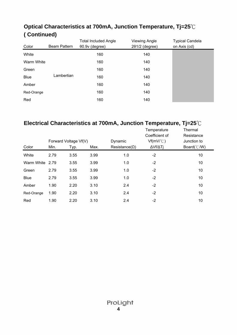
Optical Characteristics at 700mA, Junction Temperature, Tj=25( Continued)
Total Included Angle Viewing Angle Typical CandelaColor Beam Pattern θ0.9v (degree) 2θ1/2 (degree) on Axis (cd)
White
Lambertian
160 140
Warm White 160 140
Green 160 140
Blue 160 140
Amber 160 140
Red-Orange 160 140
Red 160 140
Electrical Characteristics at 700mA, Junction Temperature, Tj=25Temperature Thermal Coefficient of Resistance
Forward Voltage Vf(V) Dynamic Vf(mV/) Junction to Color Min. Typ. Max. Resistance(Ω) ∆Vf/∆Tj Board(/W)
White 2.79 3.55 3.99 1.0 -2 10
Warm White 2.79 3.55 3.99 1.0 -2 10
Green 2.79 3.55 3.99 1.0 -2 10
Blue 2.79 3.55 3.99 1.0 -2 10
Amber 1.90 2.20 3.10 2.4 -2 10
Red-Orange 1.90 2.20 3.10 2.4 -2 10
Red 1.90 2.20 3.10 2.4 -2 10
4

Absolute Maximum RatingsParameter White/Warm White/Green/BlueDC Forward Current (mA) 700 770Peak Pulsed Forward Current (mA) 1000 1100Average Forward Current (mA) 700 700ESD SensitivityLED Junction Temperature () 135 120Aluminum-core PCB Temperature() 105 105Storage & Operating Temperature() -40 to +105 -40 to +105Soldering Temperature()
Photometric Luminous Flux Bin Structure Bin Code Maximum Photometric Flux (lm)
MNP QRSTUV
Tolerance on each Luminous Flux bin is ± 15%
Color Bins for AmberBin Code
12467
Tolerance on each Color bin is ± 1nm
Color Bins for Red-OrangeBin Code
12
Tolerance on each Color bin is ± 1nm
Amber/Red-Orange/Red
113.6 147.7
5
±16000V HBM
Minimum Photometric Flux (lm)
260 for 5 seconds Max.
67.2
Minimum Dominant Wavelength (nm)
18.1
39.8
23.530.6
51.7
13.918.123.530.6
87.4
39.851.767.2
Minimum Dominant Wavelength (nm) Maximum Dominant Wavelength (nm)584.5 587.0
87.4 113.6
610.0 613.5
594.5 597.0
587.0 589.5589.5 592.0
613.5 620.5
592.0 594.5
Maximum Dominant Wavelength (nm)

Color Bins for RedBin Code
245
Tolerance on each Color bin is ± 1nm
Color Bins for BlueBin Code
A123456
Tolerance on each Color bin is ± 1nm
Color Bins for GreenBin Code
123456
Tolerance on each Color bin is ± 1nm
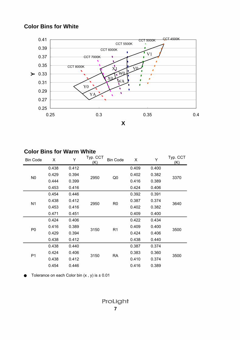
Color Bins for WhiteBin Code X Y Typ. CCT
(K) Bin Code X Y Typ. CCT(K)
0.346 0.359 0.316 0.3330.344 0.344 0.317 0.320.329 0.331 0.308 0.3110.329 0.345 0.305 0.3220.367 0.4 0.329 0.3690.362 0.372 0.329 0.3450.329 0.345 0.305 0.3220.329 0.369 0.301 0.3420.329 0.345 0.308 0.3110.329 0.331 0.311 0.2930.317 0.32 0.29 0.270.316 0.333 0.283 0.2840.329 0.331 0.303 0.3330.33 0.31 0.308 0.3110.311 0.293 0.283 0.2840.308 0.311 0.274 0.301
Tolerance on each Color bin (x , y) is ± 0.01
6
YA 8000
Y0 8000
W0 6050
WA 6300
X0 6700
X1 6300
5350V0
V1 5500
540 545545 550
530 535535 540
520 525525 530
485 490
Minimum Dominant Wavelength (nm) Maximum Dominant Wavelength (nm)
475 480480 485
465 470470 475
Minimum Dominant Wavelength (nm) Maximum Dominant Wavelength (nm)
460 465455 460
Minimum Dominant Wavelength (nm)613.5620.5631.0 645.0
631.0620.5
Maximum Dominant Wavelength (nm)
Color Bins for White
Color Bins for Warm WhiteBin Code X Y Typ. CCT
(K) Bin Code X Y Typ. CCT(K)
N0
0.438 0.412
2950 Q0
0.409 0.400
33700.429 0.394 0.402 0.3820.444 0.399 0.416 0.3890.453 0.416 0.424 0.406
N1
0.454 0.446
2950 R0
0.392 0.391
36400.438 0.412 0.387 0.3740.453 0.416 0.402 0.3820.471 0.451 0.409 0.400
P0
0.424 0.406
3150 R1
0.422 0.434
35000.416 0.389 0.409 0.4000.429 0.394 0.424 0.4060.438 0.412 0.438 0.440
P1
0.438 0.440
3150 RA
0.387 0.374
35000.424 0.406 0.383 0.3600.438 0.412 0.410 0.3740.454 0.446 0.416 0.389
Tolerance on each Color bin (x , y) is ± 0.01
7
0.25
0.27
0.29
0.31
0.33
0.35
0.37
0.39
0.41
0.25 0.3 0.35 0.4
X
Y
Y0
V1
V0
YA
WA
X1
X0W0
CCT 4500KCCT 5000KCCT 5500K
CCT 6000K
CCT 7000K
CCT 8000K

Color Bins for Warm White
8
0.34
0.36
0.38
0.4
0.42
0.44
0.46
0.36 0.4 0.44 0.48
X
Y
R1
CCT 3250KCCT 3490KCCT 3800KCCT 3050K CCT 2850K
R0
N1
N0
RA
P1
Q0P0
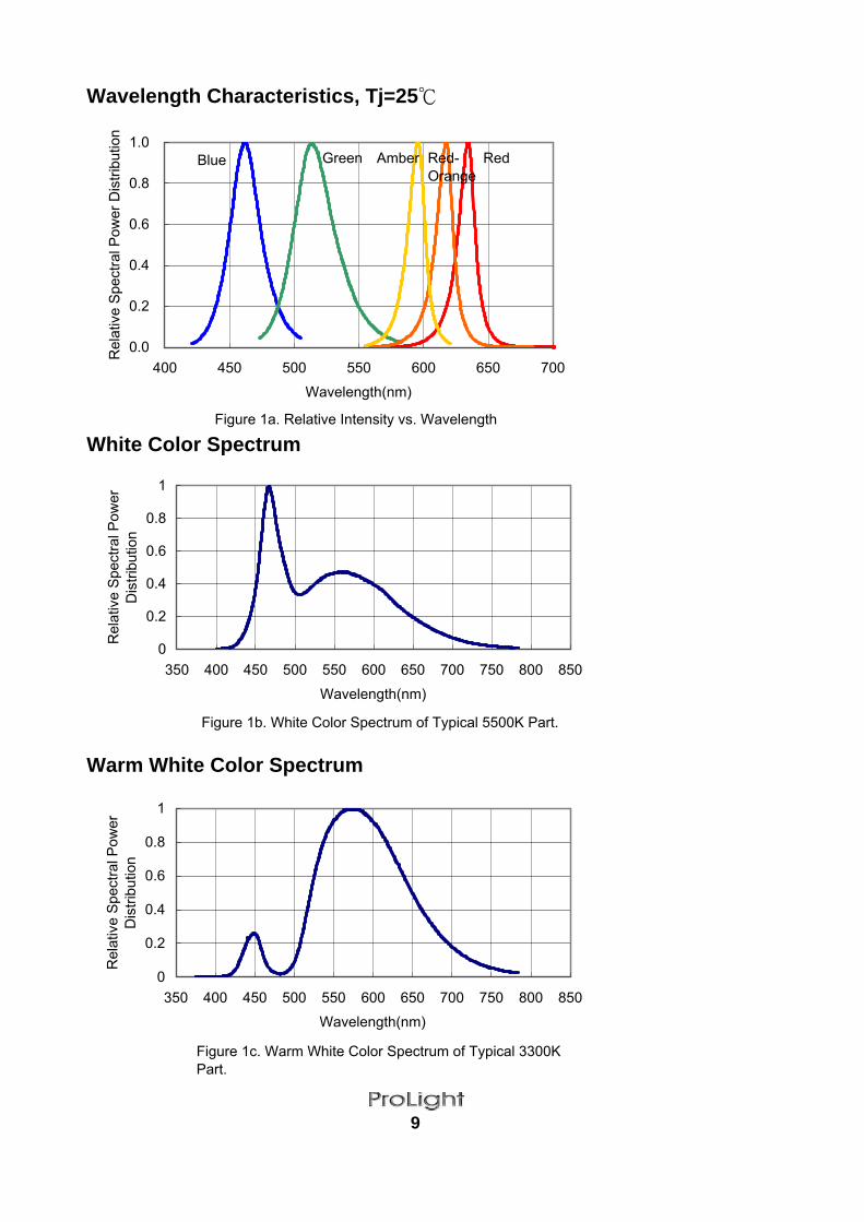
Wavelength Characteristics, Tj=25
White Color Spectrum
Warm White Color Spectrum
9
0.0
0.2
0.4
0.6
0.8
1.0
400 450 500 550 600 650 700
Wavelength(nm)
Rel
ativ
e Sp
ectra
l Pow
er D
istri
butio
n
Blue RedGreen
0
0.2
0.4
0.6
0.8
1
350 400 450 500 550 600 650 700 750 800 850
Wavelength(nm)
Rel
ativ
e Sp
ectra
l Pow
erD
istri
butio
n
Figure 1a. Relative Intensity vs. Wavelength
Figure 1b. White Color Spectrum of Typical 5500K Part.
Red-Orange
0
0.2
0.4
0.6
0.8
1
350 400 450 500 550 600 650 700 750 800 850
Wavelength(nm)
Rel
ativ
e Sp
ectra
l Pow
erD
istri
butio
n
Figure 1c. Warm White Color Spectrum of Typical 3300KPart.
Amber
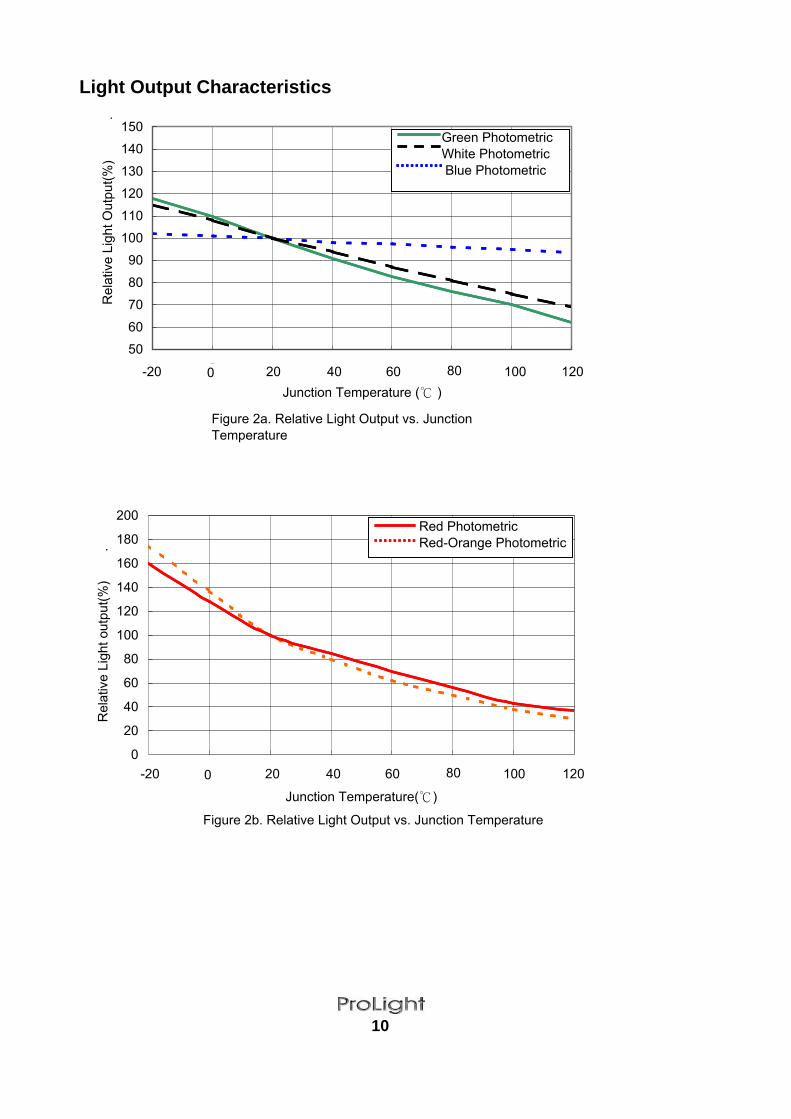
Light Output Characteristics
10
50
60
70
80
90
100
110
120
130
140
150
1 2 3 4 5 6 7 8
Junction Temperature ( )
Rel
ativ
e Li
ght O
utpu
t(%)
.
Green Photometric White Photometric Blue Photometric
Figure 2a. Relative Light Output vs. JunctionTemperature
0
20
40
60
80
100
120
140
160
180
200
1 2 3 4 5 6 7 8
Junction Temperature()
Rel
ativ
e Li
ght o
utpu
t(%)
.
Red Photometric Red-Orange Photometric
Figure 2b. Relative Light Output vs. Junction Temperature
-20 0 20 40 60 80 100 120
-20 0 20 40 60 80 100 120
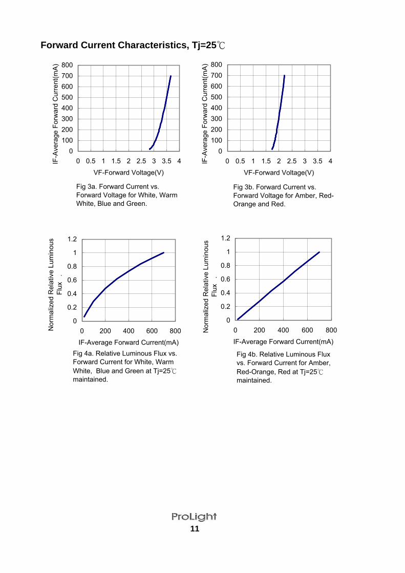
Forward Current Characteristics, Tj=25
11
0100200300400500600700800
0 0.5 1 1.5 2 2.5 3 3.5 4
VF-Forward Voltage(V)
IF-A
vera
ge F
orw
ard
Cur
rent
(mA
)
0100200300400500600700800
0 0.5 1 1.5 2 2.5 3 3.5 4
VF-Forward Voltage(V)
IF-A
vera
ge F
orw
ard
Cur
rent
(mA
)
Fig 3a. Forward Current vs.Forward Voltage for White, WarmWhite, Blue and Green.
Fig 3b. Forward Current vs.Forward Voltage for Amber, Red-Orange and Red.
0
0.2
0.4
0.6
0.8
1
1.2
0 200 400 600 800
IF-Average Forward Current(mA)
Nor
mal
ized
Rel
ativ
e Lu
min
ous
Flux
.
0
0.2
0.4
0.6
0.8
1
1.2
0 200 400 600 800
IF-Average Forward Current(mA)
Nor
mal
ized
Rel
ativ
e Lu
min
ous
Flux
.
Fig 4a. Relative Luminous Flux vs.Forward Current for White, WarmWhite, Blue and Green at Tj=25maintained.
Fig 4b. Relative Luminous Fluxvs. Forward Current for Amber,Red-Orange, Red at Tj=25maintained.
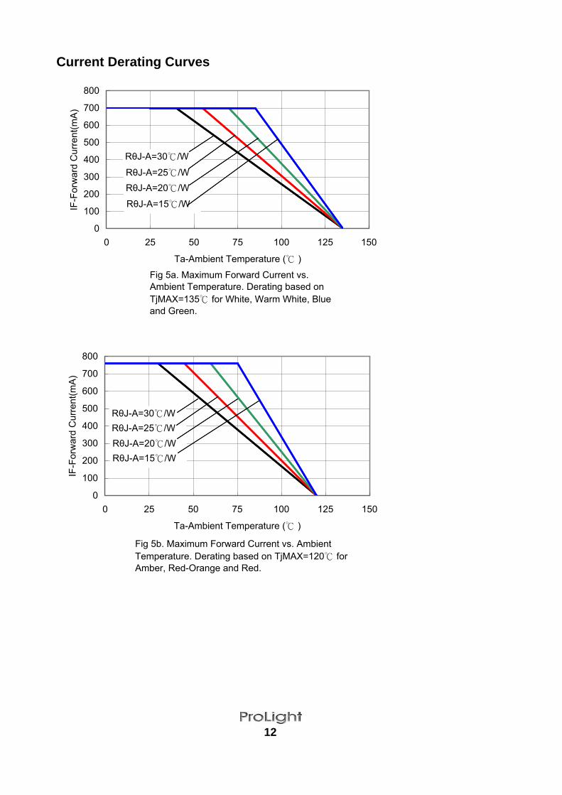
Current Derating Curves
12
0
100
200
300
400
500
600
700
800
0 25 50 75 100 125 150
Ta-Ambient Temperature ( )
IF-F
orw
ard
Cur
rent
(mA
)
0
100
200
300
400
500
600
700
800
0 25 50 75 100 125 150
Ta-Ambient Temperature ( )
IF-F
orw
ard
Cur
rent
(mA
)
Fig 5a. Maximum Forward Current vs.Ambient Temperature. Derating based onTjMAX=135 for White, Warm White, Blueand Green.
Fig 5b. Maximum Forward Current vs. AmbientTemperature. Derating based on TjMAX=120 forAmber, Red-Orange and Red.
RθJ-A=30/W
RθJ-A=30/W
RθJ-A=25/W
RθJ-A=15/W
RθJ-A=20/W
RθJ-A=20/W
RθJ-A=15/W
RθJ-A=25/W
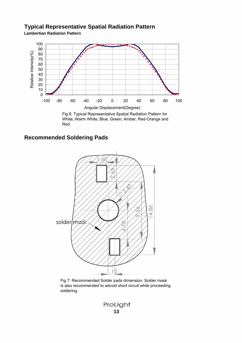
Typical Representative Spatial Radiation PatternLambertian Radiation Pattern
Recommended Soldering Pads
13
0102030405060708090
100
-100 -80 -60 -40 -20 0 20 40 60 80 100
Angular Displacement(Degree)
Rel
ativ
e In
tens
ity(%
)
Fig 6. Typical Representative Spatial Radiation Pattern forWhite, Warm White, Blue, Green, Amber, Red-Orange andRed.
Fig 7. Recommended Solder pads dimension. Solder maskis also recommended to advoid short circuit while proceedingsoldering.

Heat Plate Soldering Condition
Heat Plate temperature: 230'C max for Lead Solder and 260'C max for Lead-Free Solder When soldering, do not put stress on the LEDs during heating. After soldering, do not warp the circuit board. Air Reflow Process are not allow, it will cause optical lens damage and effect optical performance.
Manual Hand Soldering
Hand solder the leads with a solder tip temperature of 230'C for less than 5 sec. Avoiding damage to the emitter or to the MCPCB dielectric layer. Damage to the epoxy layer can cause
Do not let the solder contact from solder pad to back-side of MC PCB. This one will cause a short circuit and damage emitter.
14
a short circuit in the array.
For Prototype builds or small series production runs it possible to place and solder the emitters by hand.
MC PCB
Heat Plate
Use Solder Mask to print solder paste on MC PCB
Place emitter on the MC PCB
Heat Plate
Put MC PCB on Heat Plate until solder paste melt.The solder paste sould be melted within 10sec.Take out MC PCB out from Heat Plate within 15sec.
Put MC PCB on Heat Plate
Place solder wire to the solder pad of MC PCB
MC PCBSolder Paste
Heat Plate
(1) Soldering Process for Solder Paste (2) Soldering Process for Solder Wire
Heat Plate
Solder Wire
Put emitter on MC PCB. Take the MC PCB outfrom Heat Plate within 10 sec.
Thermal PasteMC PCB
Place solder paste on the MC PCB Place emitter on the MC PCB Use Soldering Iron to solder thelead of emtter.
Solder IronSolder Wire
emitter

Emitter Tube Packaging
15
Notes:1. 50pieces per tube.2. Drawing not to scale.3. All dimensions are in millimeters.4 .All dimendions without tolerances are for reference only.


![1312 [51.7] 30 A 1498](https://img.dokumen.tips/doc/110x75/61b149b38d976a20e8422984/1312-517-30-a-1498.jpg)
