Embed Size (px)
Citation preview

1
Techno-economic investigation of alternative propulsion plants for Ferries and RoRo ships
George A. Livanosa*, Gerasimos Theotokatosb, Dimitrios-Nikolaos Pagonisa
aDepartment of Naval Architecture, Ag. Spyridonos Street, Egaleo GR 12210, Greece
bDepartment of Naval Architecture & Marine Engineering, 100 Montrose Street, Glasgow G4 0LZ, UK
Abstract
In this paper, the main alternative propulsion plants based on reciprocating internal combustion engines
of a ferry or RoRo ship operating in routes that include Emission Control Areas (ECAs) are
comparatively assessed. Specifically, a dual fuel engine propulsion plant is compared with a
conventional Diesel engine plant. For both cases, the installation of a Waste Heat Recovery system,
which covers a part of the ship electric energy demand, is also considered. The ship main DF engines
are assumed to operate using LNG and a small amount of MDO for initiating combustion, whereas low
sulphur MDO was regarded as the fuel for the case of the Diesel engine plant. The installation of
selective catalytic reduction (SCR) after-treatment unit for reducing the NOx emissions for the case of
Diesel engines plant is also taken into account. The propulsion plants were modelled under steady state
conditions, and the simulation results were analysed in order to compare the alternative configurations.
Furthermore, the energy efficiency design index (EEDI) values were calculated and the two examined
propulsion system cases were compared on EEDI basis. Finally, the Life Cycle Cost for each
alternative propulsion plant was calculated and used for completing an economic evaluation of the
Dual fuel propulsion plant versus the conventional designs applied in ferries.
Keywords: Ferries propulsion plant, Dual fuel engines, waste heat recovery systems, EEDI, techno-
economic assessment
2
1. Introduction
The increased pressure for greener shipping resulted in an updated legislation framework set by the
International Maritime Organization (IMO), for constraining the greenhouse gaseous emissions, mainly
the carbon dioxide, as well as the nitrogen oxides (NOx) and sulphur oxides (SOx). Thus, in the recent
amendment of IMO rules [1-3], the Energy Efficiency Design Index (EEDI) and the Ship Energy
Efficiency Management Plan (SEEMP) were introduced focusing on the reduction of CO2 emissions
and fuel consumption throughout the ship lifetime. For reducing SOx emissions, the IMO [4] defines
the upper limits of the sulphur content for the fuels used onboard ships sailing inside and outside
Emission Control Areas (ECA). Presently, the use of marine fuels with up to 1% sulphur content is
only permitted inside ECAs, whereas the allowed fuel sulphur content value will be drastically reduced
reaching 0.1% from 2015 onwards. For the NOx emissions, the three tier program [5] has been
established according to which, Tier II that requires 15% reduction of NOx compared to Tier I is
currently in effect, whereas Tier III imposes 80% reduction in NOx (also compared to Tier I) and will
come into effect possibly in 2016.
To cope with the continuously increasing environmental demands, a number of measures for the ship
propulsion system can be taken; these comprise the induction of more optimised propulsor designs
including wing thrusters and contra rotating propellers, as well as the replacement of the conventional
mechanical system by the more flexible Diesel-Electric propulsion system or combined Diesel
mechanical/electric propulsion systems [6]. However, in order for the ship propulsion engines running
on Heavy Fuel Oil (HFO) or Marine Diesel Oil (MDO) to comply with the future environmental
regulations [7], techniques such as Selective Catalytic Reduction (SCR) or Exhaust Gas Recirculation
(EGR) might be required for reducing the NOx emissions, whereas exhaust scrubbers or alternatively
separate low sulphur fuel systems have to be installed onboard for addressing the SOx emissions
reduction issue [8-9]. These measures deteriorate the ship propulsion plant efficiency and as a result
increase the CO2 emissions as well as the ship operational cost. All the above, in conjunction with the
unprecedented rising of fuel oil prices throughout the last years and the continuously increasing
availability of natural gas resources around the globe [10] render the use of Liquefied Natural Gas
(LNG) as an alternative marine fuel attractive. LNG fuel is presently established as a clean and reliable
fuel for propulsion and auxiliary power generation and its usage forms a very efficient way for
reducing emissions [11]. Indeed, the SOx emissions are totally eliminated owing to the fact that
sulphur is not contained in LNG, whereas the NOx emissions can be reduced up to 85% owing to the
fact that the combustion takes place at air–fuel ratio values around 2.1 to 2.3 (lean burn combustion
concept). In addition, the reduction of CO2 emissions can reach 25%-30% thanks to the low carbon to
hydrogen ratio of fuel. On top of the above, the DF engines exhibit very low particulate emissions
level, no visible smoke and no sludge deposits [12]. The LNG infrastructure has been developed in the
last years [13], particularly in Norway, to the extent that other ship types, like Ro-Ro and smaller
ferryboats can be bunkered.
3
The use of liquefied fuels (LNG/LPG) for the ship propulsion is not a new idea; these fuels have been
used for many years onboard liquefied gas carriers equipped with steam turbine propulsion systems.
Recently, four-stroke diesel mechanical or diesel-electric propulsion systems [14] have been also used.
The former provide greater increase of the propulsion plant efficiency, whereas the latter combine the
high efficiency with the increased flexibility. In all these cases, the boil-off gas produced due to
evaporation inside the ship cargo tanks has been used as the main fuel in the ship propulsion system.
Nowadays, the commercial available gas engine portfolio includes three main technologies [15]: Gas,
Gas-Diesel (GD), and Dual-Fuel (DF) engines. Gas engines are of the four-stroke type and run
exclusively on gas. The combustion of the gas-air mixture takes place based on the Otto cycle triggered
by spark plug ignition, whereas the gas is injected into the engine cylinder ports upstream the engine
valves at low pressure (4–6 bar). The GD engines can operate on different mixtures of gas and diesel
fuels or alternatively on diesel fuel only. The engine cylinder processes follow the Diesel cycle
(compression–ignition) and the gas is injected into the engine cylinder during the compression stroke at
high pressure (up to 300 bar). These engines could be either of the two-stroke or four-stroke type. Dual
Fuel engines are of the four-stroke type and can run in gas or diesel modes. In the gas mode, 99% of
the fuel is gas and 1% (the pilot fuel) is diesel fuel. The gas is injected into the engine ports at low
pressure (4–6 bar), whereas the combustion of the gas-air mixture takes place following the Otto cycle
with the ignition being triggered by the injection of the pilot diesel fuel. In the diesel mode, the fuel is
exclusively of the diesel type and the combustion of the diesel-air mixture takes place according to the
Diesel cycle. An alternative categorisation of gas fuelled engines can be accomplished based on the
ignition principle (spark ignition versus liquid fuel pilot ignition) and the combustion chamber
geometry (single chamber versus pre-chamber) [16]. The concept of using DF medium speed diesel
engines in marine propulsion plants is continuously expanding nowadays [17]; a number of ferries with
DF engines were set in operation in the area of Baltic Sea and new ferries are being designed for
operating in the Mediterranean Sea.
One of the most important issues addressed by the classification societies rules is the placement of the
LNG tanks; they are not allowed to be close to the vessel sides and must also be at a certain distance
above the ship bottom for safety reasons in case of ship grounding. The following locations have been
proposed [18-19]: a) in the centre of superstructure, inside the outer raw of cabins and in front of the
engine casing but above the public space decks so as not to obstruct the passenger flows, b) down on
the tanktop in the centre of the vessel inside the B/5 lines (B: ship breadth), c) in the ship stern, below
the swimming pool, and d) on the upper open deck if space available. Another challenge for LNG
storage comes from the larger size of the tanks [7]. In order to produce the same amount of energy, a
volume of LNG equal to 1.8 times that of diesel fuel is required. When taking into account the LNG
tank insulation volume and the maximum tank filling ratio that can be only up to 95%, the required
volume is increased to about 2.3 times compared to the respective in the case of diesel fuel. The
practical space required in the ship becomes about 4 times higher when also counting the squared void

4
space around the cylindrical LNG tank. If compared to the MDO tanks located above the ship double
bottoms, the total volume difference is somewhat smaller, about 3 times. The weight of the bunkered
LNG amount is marginally lower than that of MDO, when considering the actual fuel itself. However,
the special tank and tank room steel structure increases the total weight for LNG storage to about 1.5
times higher than the respective one required for MDO [18-19].
For further improving the ship power plant efficiency and thus, reducing the fuel consumption and CO2
emissions, waste heat recovery (WHR) systems have been used. Depending on the ship size, the
following typical options of the exhaust gas WHR systems are commonly installed [20-22]: a) systems
for the production of saturated steam indented for covering the thermal power requirements of the ship
(heating services), b) systems for generating electricity in a steam turbine driven generator (turbo-
generator), and (c) system generating electric energy in a combined steam turbine/power gas turbine
driven generator. A comprehensive review of the waste heat recovery applications for oceangoing
vessels is presented in [23]. In Dimopoulos et al [24] the modelling and optimisation of a containership
power plant system combined with a waste heat recovery system was presented. In Hountalas et al
[25], the waste heat recovery system for recovering energy from the exhaust gas of a marine two-stroke
engine is investigated comparing its obtained performance when using two different working fluids. In
Choi and Kim [26], a combined water-organic fluid waste heat recovery system for the propulsion
engine of a containership is examined. In Gewald et al [27], an integrated approach to optimise the
combined cycle overall system efficiency for three large medium speed engines was presented focusing
on the waste heat recovery cycle combined with the optimal layout of the engine cooling system. In
Burel et al [28], the power plant of a handy size tanker operating with LNG and for various alternatives
of waste heat recovery systems including steam and organic fluid cycles was studied.
Techno-economic investigation of alternative options for propulsion plants, specifically for ships
operating frequently in ECA areas, e.g. Ferries, Ro-Ro ships, handy size tankers, is a useful tool that
can delineate the cost-effective and environmental sound solutions. Such a study for the propulsion
plant of two different ferries was reported in [18], whereas a techno-economic study for a bulk carrier
propulsion system was presented in [29]. However, studies for the integrated technical-environmental
and economic assessment of gas fuelled engines combined with waste heat recovery systems for ship
propulsion plants have not been reported. In that respect, the present study focuses on the investigation
of techno-economic and environmental sustainability of four alternative propulsion plants, based on
reciprocating internal combustion engines running either on Diesel or LNG fuels, equipped or not with
waste heat recovery system for the case of a typical ferry ship operating in routes that include Emission
Control Areas (ECAs).
2. Description of investigated propulsion system
5
The propulsion system of the new built ferries should comply with the maritime regulations, provide
increased reliability and safety and additionally operate at high efficiency levels. The typical ferry
propulsion system arrangement comprises two pairs of engines of the four-stroke type, which are
connected to the respective gearboxes for driving the two ship propellers. A power take-off machine,
usually an electric generator, is also connected to each gearbox. The ship electric power demand is
covered by a number (usually three electric generators). For further increasing the efficiency and the
flexibility of the traditional ferry propulsion system, modified configurations of combined diesel-
electric and diesel-mechanical systems, which drive controllable pitch propellers, pod thrusters or
contra-rotating propellers have been proposed [6]. For the cases of ferries propulsion plants operating
on HFO, SCR units and SOx scrubbers are required in order for the ships to comply with the IMO
imposed emissions limits when sailing inside ECAs. The alternative to that option is the use of MGO
or MDO inside ECAs and switching to HFO outside ECA zones. However, the installation of a SCR
unit is still required for reducing NOx emissions in that case. The third option is the installation of DF
engines and the usage of LNG fuel for the ship main engines and generator sets.
In the present work, the power plant system diagrammatically depicted in Figure 1 is investigated. That
type of propulsion plant can be found in small to medium size ferries. The propulsion system consists
of two main engines of the four-stroke type; each one is connected to one engine controllable pitch
propeller via a gearbox unit. In addition, three generator sets are installed for covering the ship electric
power requirements. For increasing the efficiency of the power plant at ship sailing conditions, the
installation of WHR systems for recovering part of the ship main engines exhaust gas heat and
producing electric energy was also studied.
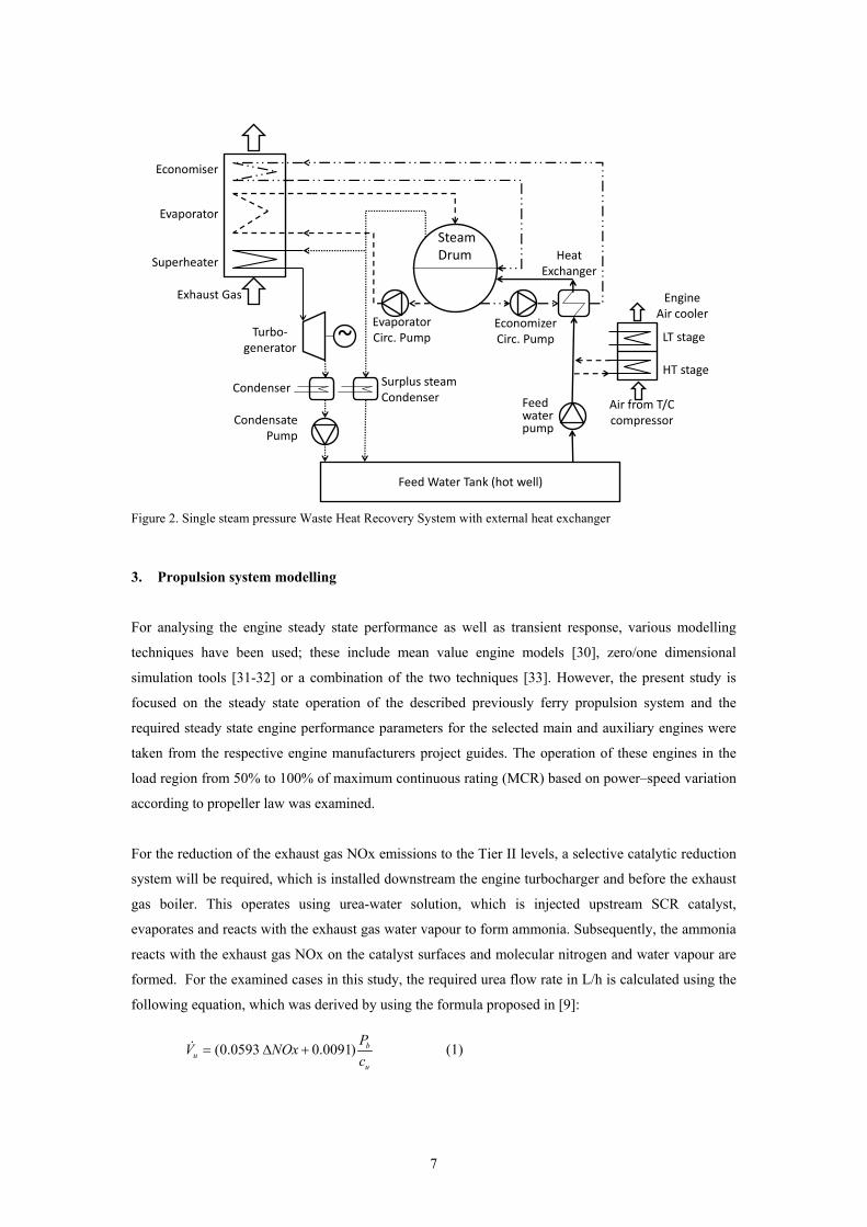
The considered WHR systems arrangement as well as their components and piping are illustrated in
Figure 2. The systems are of the single steam pressure type with external heat exchanger for heating the
feed water entering into the boiler drum. The heat exchanger is used, so that the water entering the
economiser section of the boiler is kept in a temperature level around 130oC (for the case of Diesel
fuels) in order to avoid condensing of the sulphur oxides contained in the exhaust gas, which causes
corrosion of the boiler surfaces. The option of heating the feed water using the engine air cooler is also
taken into consideration. The WHR systems are used for the production of only superheated steam,
which expands in a steam turbine coupled to an electric alternator, thus generating electricity. The
exhaust gas boiler consists of three stages; the economizer (preheater), the evaporator and the
superheater. The feed water is pumped by the feed water pump into the water/steam drum, whereas an
external heat exchanger is used for preheating it. As an option, the high temperature stage of the engine
air cooler could be also used for initially preheating the feed water. The heating medium of the heat
exchanger is the saturated water contained in the drum, which is pumped by the economizer circulating
water pump, enters the heat exchanger heating the feed water, leaves the heat exchanger with lower
temperature and then enters to the economiser section. The circulating water exiting the economizer
returns to the drum having temperature approximately equal to the saturation temperature
corresponding to the drum operating pressure. An additional circulating pump is used to circulate the

6
water through the evaporation section of the boiler, where a portion of saturated water is evaporated
and saturated steam is produced. The flow rate of this pump is usually selected two to four times the
flow rate of feed water, so that the integrity of the evaporator is not jeopardized in the case where
temporarily more steam is produced at system transients. The saturated water/steam mixture exiting the
boiler returns into the drum, where the saturated steam is separated from the water and is accumulated
in the upper part of the drum. The saturated steam is advanced into the superheater section of the
boiler. The superheated steam exiting the boiler enters into the steam turbine stages of turbogenerator,
where it expands producing mechanical power and driving the electric generator. The steam exiting the
steam turbine is advanced to the condenser, where it condenses by the usage of sea water. The
condensate is then pumped into the feed water tank (hot well) through the condensate pump. In case
where surplus amount of saturated steam is produced, it is also forwarded into the surplus steam
condenser where it converts to condensate water, which subsequently is pumped to the feed water tank.
Figure 1. Investigated Ship Propulsion Plant consisting of two main engines (Diesel or Dual-Fuel) and a WHR
systems for electric power generation
7
Figure 2. Single steam pressure Waste Heat Recovery System with external heat exchanger
3. Propulsion system modelling
For analysing the engine steady state performance as well as transient response, various modelling
techniques have been used; these include mean value engine models [30], zero/one dimensional
simulation tools [31-32] or a combination of the two techniques [33]. However, the present study is
focused on the steady state operation of the described previously ferry propulsion system and the
required steady state engine performance parameters for the selected main and auxiliary engines were
taken from the respective engine manufacturers project guides. The operation of these engines in the
load region from 50% to 100% of maximum continuous rating (MCR) based on power–speed variation
according to propeller law was examined.
For the reduction of the exhaust gas NOx emissions to the Tier II levels, a selective catalytic reduction
system will be required, which is installed downstream the engine turbocharger and before the exhaust
gas boiler. This operates using urea-water solution, which is injected upstream SCR catalyst,
evaporates and reacts with the exhaust gas water vapour to form ammonia. Subsequently, the ammonia
reacts with the exhaust gas NOx on the catalyst surfaces and molecular nitrogen and water vapour are
formed. For the examined cases in this study, the required urea flow rate in L/h is calculated using the
following equation, which was derived by using the formula proposed in [9]:
(0.0593 0.0091) bu
u
PV NOx
c (1)
~
Feed Water Tank (hot well)
Economiser
Evaporator
Superheater
Exhaust Gas
Steam Drum
Condensate Pump
Condenser Surplus steamCondenser
Turbo‐generator
EconomizerCirc. Pump
EvaporatorCirc. Pump
Heat Exchanger
Air from T/C compressor
Engine Air cooler
HT stage
LT stage
Feed water pump

8
where Pb is the engine brake power in kW, ΔNOx is the expected reduction of specific NOx emissions
in g/kWh and cu is urea mass fraction percentage of the used urea-water solution.
Although, there is exhaust gas temperature changing from the urea solution injection point till the SCR
unit exit (initially the exhaust gas is cooled due the urea-water evaporation; heating of exhaust gas
takes places in catalyst surfaces due to the reaction exothermic nature), this was not taken into account.
The WHR systems operation was analysed under steady state conditions by applying the mass and
energy conservation equations in the various components of the installation as explained bellow. The
boiler transferred heat from the exhaust gas to the steam/water is calculated using the following
equation:
_ _ _( )b b g p g g i g oQ m c T T (2)
where gm is the exhaust gas mass flow rate, cp_g is the exhaust gas mean specific heat at constant
pressure, Tg_i is the temperature of the exhaust gas entering into the boiler, Tg_o is the temperature of the
exhaust gas exiting the boiler, and ηb is the boiler efficiency that is in the order of 98-99% (1- ηb is the
boiler heat transfer losses).
Considering that saturated water exits the economizer section, mixture of saturated water/steam exits
the evaporator section and superheated steam exit the superheater section, the energy balance in the
boiler gives:
_ _ _ _ _ _( ) ( ) ( ) ( )
b ec ev sh
cw ec w cw ec i cw ev w cw ev i s s w sh sh s
Q Q Q Q
m h h m h h m h h m h h
(3)
where _cw ecm is the economizer circulating water mass flow rate, _cw evm is the evaporator circulating
water mass flow rate, shm is the superheated steam mass flow rate, sm is the mass flow rate of the
saturated steam produced in the evaporator, hcw_ec_i is the specific enthalpy of the circulating water
entering into the economizer (which is exiting from the external heat exchanger), hsh is the specific
enthalpy of the superheated steam exiting the boiler, hcw_ev_i is the specific enthalpy of the circulating
water entering into the evaporator (exiting the evaporator circulating water pump), hw and hs are the
specific enthalpies of saturated water and steam, which form the saturated mixtureexiting the
evaporator, respectively.
The energy conservation applied to the system water/steam drum, feed water tank and heat exchanger
respectively, gives the following equations:
_ _ _ _( )( ) ( )cw ec cw ev cw w fw fw d i wm m h h m h h (4)
_ _ _ _ _ _ _ _ _( ) ( )cw ec cw ec pd cw ec i fw fw d i fw HE im h h m h h (5)

9
_fw fw sh c pdm h m h (6)
where fwm is the feed water mass flow rate, hcw is the specific enthalpy of the water contained within
the drum, hfw_d_i is the specific enthalpy of the feed water entering into the drum (exiting the heat
exchanger), hcw_ec_pd is the specific enthalpy of the circulating water exiting the economizer circulating
water pump (entering the heat exchanger), hfw_HE_i is the specific enthalpy of the feed water entering the
heat exchanger (for the case of no heating of the feed water in the engine air cooler this coincides to the
specific enthalpy of the feed water exiting the feed water pump, hfw_pd), hfw is the specific enthalpy of
the feed water contained within the feed water tank, hc_pd is the specific enthalpy of condensate water
exiting the condensate pump (entering the feed water tank), respectively.
The heat exchanger effectiveness is defined by the following equation:
_ _ _ _
_ _ _ _
fw d i fw HE iHE
cw ec pd fw HE i
h h
h h
(7)
The specific enthalpy of the water exiting the system pumps are calculated as follows:
_ _ /i pd i pu i ih h P m (8)
where Pi is the pump power, im is the pump mass flow rate, hi_pu and hi_pd are the fluid specific
enthalpies upstream and downstream the pump, respectively, and i = fw for the feed water pump, i =
cw_ec for the economizer circulating water pump, i = cw_ev for the evaporator circulating water pump,
i = c for the condensate water pump.
The power for each one of the system pumps is calculated based on the pump pressure increase,
efficiency and fluid density as follows:
/ ( )P m p (9)
where Δpi is the pump pressure increase; ηi is the pump efficiency and ρi is the fluid density.
In the case where the high temperature stage of the engine air cooler is used for heating the feed water
tank, the energy balance in the air cooler provides:
_ _ _ ac a _ a ac _ _ ac _ _( ) ( )fw fw HE i fw pd p HT i HT om h h m c T T (10)
where am is the air mass flow rate entering the engine air cooler, cp_a is the mean specific heat at
constant pressure of the air in the high temperature stage of the engine air cooler, Tac_HT_i is the
temperature of the air entering the high temperature stage of the engine air cooler, Tac_HT_o is the
temperature of the air exiting the high temperature stage of the engine air cooler and and ηac is the air
cooler efficiency that is in the order of 99.5% (1- ηac is the air cooler heat transfer losses).
The mass balance in the waste heat recovery system gives:
fw s shm m m (11)
The circulating pumps mass flow rates were calculated by estimating the respective ratio values:

10
_ _ _ _,cw ec cw ec fw cw ev cw ev fwm r m m r m (12)
where rcw_ev is the ratio of evaporator circulating water mass flow rate to the feed water mass flow rate
and rcw_ec is the ratio of economiser circulating water mass flow rate to the feed water mass flow rate.
The equations (2)-(12) form an algebraic system of equations with unknowns the mass flow rates and
specific enthalpies of water and steam. This is solved iteratively using as initial value of the
superheated steam mass flow rate the estimation that provides the ideal Rankine cycle consideration as
well as the following input: a) the engine exhaust gas mass flow rate, temperature and equivalence ratio
as well as the temperature of the air exiting the turbocharger compressor, b) the pressure of the drum
water/steam, c) the pressure and temperature of the feed water tank, d) the way of feed water heating
(no heating, using saturated steam or using the engine air cooler) e) the pressure losses in the various
boiler sections and the piping of the WHR installation, f) the ratio of the economizer circulating water
to the produced saturated steam mass flow rates and the ratio of the evaporator circulating water to the
produced saturated steam mass flow rates, g) the mass flow rate of saturated steam required for the ship
heating services, h) the boiler efficiency, the pumps efficiency, the external heat exchanger
effectiveness and the air cooler efficiency, i) the temperature of superheated steam exiting the boiler, j)
the temperature drops at various sections of the WHR installation, k) the condenser pressure, and l) the
algebraic equations for the calculation of the properties of water/steam, exhaust gas and air.
The WHR system produced electric power is calculated by the following equation:
el sh ST TG b T LP m AE f f f (13)
where STAE is the available specific energy in the steam turbine (corresponds to the steam isentropic
expansion), ηTG is the efficiency of the turbo-generator, and fb, fT, fL are correction factors for the steam
turbine back pressure, steam temperature and steam turbine load, respectively. Data for the estimation
of turbo-generator efficiency and the correction factors are given in [34].
The specific enthalpy of the steam exiting the steam turbine and entering the condenser is calculated
by:
_ _ST o ST i ST STh h AE (14)
where hST_i is the specific enthalpy of the saturated steam entering the steam turbine, ηST = ηTG/(ηG ηm)
is the steam turbine efficiency, ηG is the generator efficiency, and ηm is the turbogenerator mechanical
efficiency.
The steam exiting the steam turbine is condensed by using sea water in the system condenser. The
power of the sea water pump was also calculated by using eq. (9). The required sea water mass flow
rate is calculated by the following equation, which was derived by applying the energy balance in the
condenser:
_ _ _ _( ) / ( )c sw sh ST o c w p sw swm m h h c T (15)

11
where _c wh is the specific enthalpy of the condensate water exiting the condenser, cp_sw is the condenser
sea water specific heat, and ΔTsw is the temperature increase of the sea water in the condenser.
For the examined case, where saturated steam is not used for the ship heating services, the increase in
the ship propulsion installation efficiency due to the electric power generation is calculated by the
following equation:
( ) / ( )el f Lpumps
P P m H (16)
where fm is mass flow rate of the engine fuel and HL is the fuel lower heating value.
The minimum temperature difference (pinch point) is calculated using the following equation, which is
derived using the energy balance in the evaporator and superheater sections of the boiler:
__
ev shpp g i s
b g p g
Q QT T T
m c
(17)
4. IMO Energy Efficiency Design Index Calculation
The Marine Environmental Protection Committee (MEPC) of the IMO [2] introduced the ship Energy
Efficiency Design Index (EEDI) as a measure of ships CO2 emissions, which, in the case of new built
cargo ships (no ice-class), is calculated by the following formula:
eff AEeff FAE AEP C SFOC P C SFOC f P C SFOCME FME ME AE FAE AEEEDI
Capacity Vref
(18)
where EEDI is in g CO2/t/NM, CF is a conversion factor between fuel consumption (in g) and CO2
emissions (also in g) and is based on fuel carbon content; CF = 3.206 g CO2/g fuel for the case of
Diesel Gas/Oil and CF= 2.750 g CO2/g fuel for the case of LNG, ME and AE refer to the main and
auxiliary engine(s), respectively; Capacity is taken the ship deadweight (DWT) for the cargo ships and
the ship gross tonnage (GT) for the Ro-Pax ferries; PME is defined as the 75% of the rated installed
power of the main engine after having deducted any installed shaft generator power; PAE is the required
auxiliary engine power to supply normal maximum sea load including necessary power for
propulsion/machinery systems but excluding any other power e.g. ballast pumps, thrusters, cargo gear
etc, in the condition where the ship engaged in voyage at the speed Vref under the design loading
condition; PAEeff is the auxiliary power reduction due to innovative electrical energy efficient
technology (e.g. WHR) measured at PME; feff is the availability factor of each innovative energy
efficiency technology; SFOCME and SFOCAE are the brake specific fuel oil consumptions (in g/kWh) of
the main and auxiliaries engines at the 75% and 50% of their MCR points, respectively.
12
The baseline value of EEDI can be defined, based on regression analysis of data of several ships. For
the case of RoRo cargo ships, the following expression was proposed [35]:
0.71419788EEDI DWT
(19)
5. Financial evaluation of investments in maritime sector
The economic analyses of the alternative configurations for the ship propulsion plant are based on the
calculation of the respective annual machinery cost, which consists of the Capital and the Operational
expenditures. The Capital Expenditure (CAPEX) is the constant annual instalment to which the initial
investment cost (IC) is equally distributed throughout the investment lifetime (n) under a determined
discount rate (R) and can be calculated by the following equation given by VDI 2067 [36]:
∙ ∙ (20)
The discount rate, which alternatively referred as the cost of capital, opportunity cost, or weighted
average cost of capital, is used for spreading the investment cost over the expected investment life or it
can be used for determining the present value of future benefits or costs. It can have a large impact on
the results, and therefore, the selection of the proper value for the discount rate is important for
accurately determining the capital expenditure. A minimum “risk free” discount rate values in the order
of 4.0 to 4.5% for using in marginal abatement cost analysis of energy efficiency measures (including
WHR) has been proposed in [37]. A discount rate value around 10% appears to be adequate for the cost
analysis studies of marine industry.
The Operation Expenditure (OPEX) is the sum of the Annual Fuel consumption Cost (AFC) (including
HFO, MDO and LNG), the Annual Lubricating Oil consumption Cost (ALOC), the Annual
Maintenance Cost (AMC) and the Annual Urea solution consumption Cost (AUC) for the case where a
SCR system is used. All those costs are calculated using main engine (subscript MEi) and auxiliary
engines (subscript AEi) a) specific fuel oil consumptions for pilot - ( , ) and main
fuel ( , ), b) specific lubricating oil consumptions ( , ), c) annual
operating profile of the plant expressed in running hours ( , ) at certain load levels ( ,
), d) fuel prices ( , ) , e) lube oil price ( ), f) labour and parts prices expressed as
specific maintenance cost ( , ), g) urea price ( and SCR system urea specific
consumption ( , ). The OPEX is expressed by the following equation:
A A A A (21),
where:

13
∙ ∙ ∙ ∙ ∙
∙ ∑ ∙ ∙ ∙ ∙ (22)
∑ ∙ ∙ ∙ ∙ ∙ (23)
∑ ∙ ∙ ∙ ∙ (24)
∑ ∙ ∙ ∙ ∙ ∙ (25)
where N is the number of operating conditions (i.e. sailing, manoeuvring, waiting in port).
6. Case Study
The ship investigated in this paper is a ferry or Ro-Ro cargo ship, whose general characteristics are
presented in Table 1. The required ship propulsion power of 17 MW should be delivered by two four-
stroke reciprocating engine units of 8.5 ΜW (or more), whereas three generating sets of 1 MW power
are required for covering the ship electric energy demand. The ship is considered to sail in a route of
1160 NM, which includes a part of 340 NM inside ECA. An example of this route is the itinerary
between the ports of Trieste (Italy) and Istanbul (Turkey). Each leg of ship voyage lasts approximately
58 h considering a sailing speed of 20 knots; 57 h sailing and 0.5 h manoeuvring time at each port. It is
also assumed that the ship stays 7 h on each port of her voyage and operates 80% of the calendar year.
In specific, the ship spends her annual operating hours, as follows: 5.4% in ECA Ports, 5.4% in Non-
ECA Ports, 0.39% manoeuvring in ECA waters, 0.39% manoeuvring in Non-ECA waters, 25.9%
sailing in ECA open sea and 62.5% sailing in Non-ECA open sea.
The following alternative propulsion plants are investigated in the present study: a) The vessel is
equipped with two medium speed diesel engines for propulsion and three diesel generating sets (for
example the W9L46 marine Diesel engine [38] and the W6L20 generating set [39] respectively, both
from Wärtsilä), running on Marine Gas Oil (MGO) within ECA zones and on Low Sulphur Heavy Fuel
Oil, outside ECA zones. A selective catalytic reduction system (SCR) is considered to be installed for
reducing NOx emissions when the ship operates within ECA zones (fulfillment of IMO Tier III
emission level). The SCR system is consuming urea solution and is switched off when the Ferry is
sailing in Non-ECA zones, where the less strict NOx emission levels (IMO Tier II) can be met by the
engines, without any exhaust gas after-treatment system. b) The vessel is equipped with two medium
speed dual fuel engines for propulsion and three dual fuel generating sets (for example the W9L50DF
[40] dual fuel marine engine and the W9L20DF dual fuel generating set [39] respectively, both from
Wärtsilä), continuously running on LNG. A small amount (around 1% on energy basis) of MGO is also

14
injected in engines cylinders for combustion commencement. The combustion of LNG enables the
engines to meet the emission limits inside and outside ECA zones. c) This configuration is as the case
(a) with the addition of a waste heat recovery system (WHR), recovering energy from the main engines
exhaust gases for producing superheated steam, to be expanded in a steam turbine coupled to an
electric alternator. d) This configuration is as the case (b) with the addition of the waste heat recovery
system described above. The advantage of the configurations with WHR systems is that electricity can
be generated onboard by the turbo-generators, enabling the ship operator to unload or even switch off
one of the ship generating sets. The main engine parameters of the selected Diesel and DF engines are
given in Table 2.
Table 1. Ferry Main Particulars
Characteristic Value Size 35000 GT Length 220 m Beam 28.2 m Draft 7.0 m Speed (service) 21.0 knots Deadweight 12500 mt Propulsion Power (installed) 17.0 MW Aux. Power (installed) 3.0 MW Propulsion 2 CP propellers
Table 2. Main Engine Parameters
Characteristic Diesel Engine
Dual Fuel Engine
Cylinders 9L 9L Bore 460 mm 500 mm Stroke 580 mm 580 mm Brake Power at MCR 8775 kW 8775 kW Brake Power at MCR 500 rpm 514 rpm
The required engine data for modelling the WHR system include the mass flow rate, temperature and
equivalence ratio of the exhaust gas exiting engine turbocharger turbine. The latter was used for
estimating the exhaust gas composition considering perfect combustion, which, in turn, was used for
calculating the exhaust gas specific heat at constant pressure. For the case of the heating the feed water
using the engine air cooler, the temperature of the air exiting the turbocharger compressor is also
required as input. All the required parameters are taken for engine loads in the range from 50% to
100% of MCR, considering that the engines operate according to propeller law and ISO ambient
conditions, using the data given in the engine project guides [38-40]. An increase by 3% for the
reported values brake specific fuel consumption was taken into account since the manufactures give the
engine BSFC values with a tolerance of ±5%. The shafting system efficiency for all the examined cases
is considered to be 97% at MCR, whereas the correction that is given in [34] is taken in to account at
lower engine loads.
For the case of 9L46 engine operating at MCR, an exhaust gas amount of 30% was considered to
bypass the boiler, so that the boiler geometric characteristics are kept balanced. This value derived

15
considering that the available engine exhaust energy at 100% load is approximately 30% greater than
the one for the case of 85% load. Thus, the oversizing of the exhaust gas boiler is avoided, since the
engine rarely operates at 100% load. For the case of the diesel engines, the urea flow rate was
calculated using the equation reported in [9] considering a 40 wt % urea-water solution and exhaust
gas NOx emission level of 2.5 g/kWh to comply with Tier III limits. The LNG fuel composition was
taken as follows: 95% methane, 2% ethane and 3% butane; the lower heating value of that LNG was
calculated to be 49467 kJ/kg.
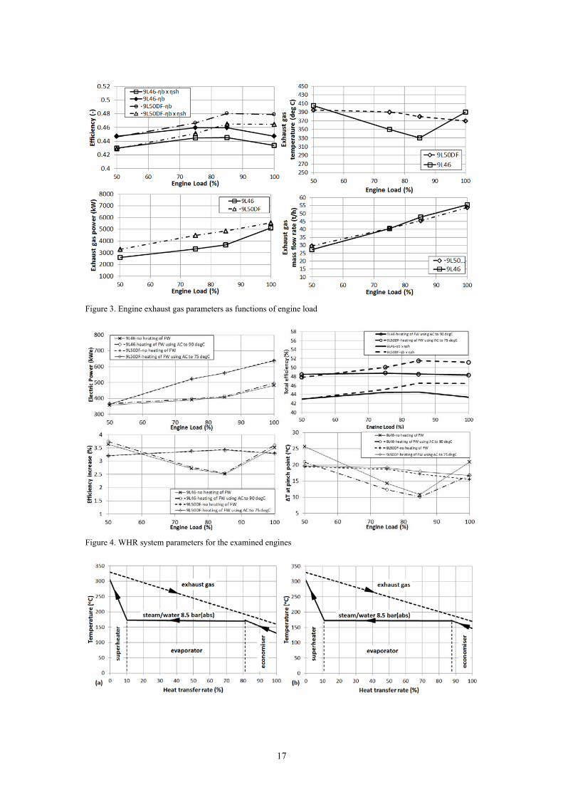
The values of the temperature and mass flow rate of the exhaust gas exiting the engine for both the
examined engines (9L46 running on MDO and 9L50DF running on LNG and using MDO pilot
injection for the start of combustion) as well as the exhaust gas thermal power, which are used in the
WHR installation simulation cases presented below, are shown in Figure 3. The brake efficiency for
both engines as well as the product of engine brake efficiency and the shafting system efficiency are
also given in Figure 3. The DF engine operates with increased efficiency 2-3% for the load region from
85% and above compared to the diesel engine. Although, the exhaust gas mass flow rates of both
engines are comparable, the exhaust gas waste thermal power are greater for the case of the dual fuel
engine due to the exhaust gas higher temperature values in the region from 55% to 95% of engine load.
A set of results including the net produced electric power, the power plant efficiency increase due to
the production of the electric power from the WHR system, the total power plant efficiency and the
minimum temperature difference at exhaust gas boiler pinch point for the cases of the 9L46 and
9L50DF engines are presented in Figure 4. The following cases for the WHR system parameters were
simulated: no heating of the feed water tank and heating the feed water using the engine air cooler. In
all the simulated cases, no production of saturated steam for the ship heating services was assumed.
The boiler drum absolute pressure was considered to be 8.5 bar, whereas the pressure of the condenser
was taken as 0.065 bar. The temperature-heat transfer rate diagrams of the exhaust gas boiler for the
9L46 engine operating at 85% load for the case of no heating the feed water tank and heating the feed
water tank using the engine air cooler are shown in Figure 5.
As it can be deduced from Figure 4, a considerable amount of electric power is produced, namely from
350 kW to 490 kW for the case of 9L46 engine and from 350 kW to 640 kW for the case of 9L50DF
engine. In the case of the dual fuel engine, the produced electric power is greater by 100 to 120 kW
when the engine operates at load region from 70% to 100% of MCR. This means that in the case of
simultaneous operation of both ship main engines at 75% load, the respective exhaust gas WHR
systems can generate 800 kWe for the case of Diesel engines and 1040 kWe for the case of DF engines.
Therefore, in the latter case, one of the ship generating sets can be switched off. The efficiency increase
owing to the net electric power generation (the power required by the WHR system pumps are
excluded) is above 2.5% for the case of 9L46 engine and above 3.2% for the case of the 9L50DF
engine, which indicates that the power plant efficiency is substantially improved when a WHR system
is used. The power plant total efficiency (the product of engine brake efficiency and the shafting
16
system efficiency plus the efficiency increase) is in the range of 48 to 49% for the case of the 9L46
engine, whereas it can reach values as high as almost 52% in the case of the 9L50DF engine.
Therefore, it is estimated that even in the case of using dual fuel-electric propulsion, the overall
propulsion system efficiency can be maintained in comparable levels to a conventional Diesel engine
propulsion system, taking into account the respective propulsion systems losses (3% for the case of a
conventional four-stroke Diesel engine propulsion system vs. 10% for the case of the dual fuel engine-
electric propulsion system, both at MCR).
The minimum exhaust gas boiler temperature difference (pinch point) is maintained above 10oC for the
case of the 9L46 engine and above 15oC for the case of 9L50DF engine, which means that the exhaust
gas boiler for the case of DF engine will be less bulky, since smaller heat transfer area is required. This
is explained by considering the temperature profiles of both engines shown in Figure 3. For the DF
engine, the exhaust gas temperature lays in the region from 370oC to 390oC with the lower temperature
obtained at 100% engine load. At that load, the minimum temperature difference is slightly above
15oC. On the other hand, for the Diesel enginethe minimum temperature of the exhaust gas is obtained
for the operating point of 85% load. At that point, the minimum temperature difference if slightly
above 10oC.. In the case of heating the feed water using the engine air cooler, the heat transfer rate of
the economiser section of the exhaust gas boiler is lower, having, as a result, the reduction of the
minimum temperature difference. Thus, higher temperature of the exhaust gas exiting the boiler is
required in order to maintain the minimum temperature difference at acceptable level. This is clearly
seen in Figure 5 comparing the left and right diagrams. The exhaust gas temperature at boiler exit is
increased by 10oC in the case of heating the feed water using the engine air cooler (Figure 5b), so that
the temperature difference at pinch point is kept above 10oC. For that reason, the electric power
production for the WHR system with the feed water heating using the engine air cooler is only
marginally improved in comparison to the feed water no heating case. In that respect, the heating of
feed water using the engine air cooler seems not to be a viable option for case of a single pressure
WHR system.
17
Figure 3. Engine exhaust gas parameters as functions of engine load
Figure 4. WHR system parameters for the examined engines
18
Figure 5. Temperature-Heat transfer rate diagrams for the exhaust gas boiler of the 9L46 engine operating at 85%
load for the cases of (a) no heating the feed water and (b) heating the feed water using the engine air cooler to
90oC
The attained Energy Efficiency Design Index (EEDI) was calculated using equation (5) considering the
Ro-Ro cargo ship case for the various options of its propulsion plant installation (diesel engine with
and without WHR, Dual Fuel engine with and without WHR). The derived results are presented in
Figure 6. As it can be observed, the calculated EEDI value for the case of Diesel engines propulsion
plant is 32.4, whereas the EEDI for the case of LNG (Dual Fuel) engines propulsion plant is 23.7. Both
values are greater than the proposed baseline EEDI value, which was found 23.5 according to equation
(6). Thus, it is inferred that even in the case of using a “clean fuel” such LNG, the attained EEDI
marginally exceeds the EEDI baseline value. This means that only the change of fuel is not adequate
for complying with the EEDI regulations, and therefore, additional measures should be taken for
increasing the ship propulsion plant efficiency in the design phase. The installation of a WHR system
belongs to the possible solutions. In such a case, significant reductions of the attained EEDI can be
obtained; from 32.4 to 30.9 for the case of Diesel engines; from 23.7 to 21.2 for the case of DF
engines. However, as it is also observed from Figure 6, only the combination of LNG and WHR can
obtain EEDI value below the baseline limit and in that respect it can be regarded as completely green
alternative propulsion plant according to the imposed IMO EEDI regulations.
The economic viability of this option will be investigated below based on figures presented in recent
publications of [18], [19] and [21]. The machinery costs estimations for each one of the ship propulsion
plant alternatives are given in Table 3. The annual machinery costs were calculated for each propulsion
plant alterative, considering 55 roundtrips per year, HFO price 483 €/t, MDO price 676 €/t, LNG price
477€/t, Urea Price 350€/t, a discount rate of 10% and duration of investment 20 years. The results are
presented in Figure 7. As can be observed from Figure 7, there are significant savings when a WHR
system is added. In detail, the savings found to be 391.1 k€/year for the case of the Diesel engines and
801,8 k€/year for the case of the LNG engines. It must be noticed that the optimum solution remains
the “LNG-WHR” propulsion plant with around 2,4 M€ annual savings compared with the “Diesel–
WHR” propulsion plant. This means that the LNG engines combined with a WHR system, despite of
the increased cost of initial investment, remain the most cost effective solution and in the same time
environmentally sound.

19
Figure 6. Calculated Energy Efficiency Design Index (EEDI) for the investigated alternative propulsion plants
Figure 7. Annual Machinery Costs
Table 3. Specific Machinery Costs
Machinery Item Cost (EUR/kW) Main Engine (Diesel) 235.00 Propulsion Line 220.00 Generating Sets 505.00 SCR system 40.00 LNG Tanks and Equipment 365.00 Waste Heat Recovery System 103.00
7. Conclusions
The techno-economic sustainability of four alternative propulsion plants, based on reciprocating
internal combustion engines running either on Diesel or LNG fuels, equipped or not with Waste Heat
Recovery systems was investigated for the of a typical ferry or Ro-Ro ship operating in a route passing
through ECA. The main findings derived from this work are summarised as follows.
0,00 €
2,00 €
4,00 €
6,00 €
8,00 €
10,00 €
12,00 €
14,00 €
LNG ‐ WHR DIESEL ‐ WHR LNG Diesel
Millions
UREA
Lube Oil Cost
Maintenance Costs
Fuel Costs
Capital Cost

20
The ship propulsion plant comprising by DF engines and running on LNG can operate with up to 2%
higher efficiency compared to the diesel engines propulsion plant. When a WHR system is used for
generating electric power, a substantial part of the ship electric energy demand can be covered. In the
case of LNG propulsion, a 3.2 to 3.5% increase in the plant efficiency was calculated, whereas the
predicted efficiency increase was from 2.5 to 3.5% in the case of diesel propulsion. More electric
power can be produced for the case of LNG propulsion. When both DF engines operate at 85% load,
the switching off of one of the generating sets is possible. For the examined single steam pressure
WHR system, the option of heating the feed water by using the engine air cooler stages does not
significantly improve the overall system efficiency, and hence, it is not considered as a viable solution,
as it can be for the WHR systems of double steam pressures.
For the Ro-Ro ship case, the diesel engines propulsion plant, even in the case where the WHR system
is installed, presented EEDI values above the proposed baseline. The DF engines propulsion plant
EEDI is in the region of the proposed baseline value (although slightly above). Only the combination
of DF engines and WHR demonted an EEDI value lower than the proposed baseline, indicating that
additional measures should be taken, so that a new built ship comply the EEDI legislation.
The economic analysis of the examined options demonstrated that although the DF engines propulsion
plant has greater initial cost, it gave lower annual cost, which is attributed to the higher overall
efficiency and the lower price of LNG compared with the MDO/MGO price. The inclusion of WHR
system further lowers the propulsion installation annual machinery cost. However, it must be noted that
the possible reduction of the transport ship capacity due to the increase volume of the LNG fuel storage
system was not taken into account in the present analysis.
In conclusion, the solution of the DF main engines running on LNG combined with a WHR system for
electricity generation was found to be technically, environmentally and economiclly sound, by reaching
the higher total energy efficiency up to 52%, the lower EEDI value (20.8) (below the limit of 23.5 for
the Ro-Ro ship case), 80% less NOx emissions, practically no sulphur emissions and a superior cost
effectiveness proved by annual saving in operating costs exceeding 2 M€ compared with the Diesel
engines alternative for the examined ship operational profile.
However, several challenges related with the use of LNG onboard, should be seriously taken into
consideration, before the final selection is made. The lack of LNG infrastructure in the majority of the
commercial ports, the limited experience from running marine engines with gas fuels, the required
safety measures, the future gas price variation are among the critical factors that should be further
investigated in the future works.

21
References
[1] IMO. 2011, Resolution MEPC.203(62), Amendments to the annex of the protocol of 1997 to amend
the international convention for the prevention of pollution from ships, 1973, as modified by the
protocol of 1978 relating thereto (Inclusion of regulations on energy efficiency for ships in MARPOL
Annex VI), MEPC 62/24/Add.1, London: International Maritime Organization.
[2] IMO. 2012, a) Resolution MEPC.212(63) Guidelines on the method of calculation of the attained
energy efficiency design index (EEDI) for new ships. MEPC 63/23, London: International Maritime
Organization.
[3] IMO. 2012, b) Resolution MEPC.213(63), Guidelines for the development of a ship energy
efficiency management plan (SEEMP), MEPC 63/23, London: International Maritime Organization.
[4] IMO, Sulphur oxides (SOx) – Regulation 14, London: International Maritime Organization.
[5] IMO, Nitrogen Oxides (NOx) – Regulation 13, London: International Maritime Organization.
[6] Levander, O. (2009) New Concepts in Ferries propulsion, Wärtsilä Publication, 01/2009, pp. 1-11.
[7] Wik, Ch. (2013) Tier III technology development and its influence on ship installation and
operation, In Proceedings of the 27th CIMAC World Congress. Shanghai. China. 13–16 May 2013.
Paper No: 159.
[8] MAN Diesel and Turbo. (2008) Exhaust Gas Emission Control Today and Tomorrow-Application
on MAN B&W Two-stroke Marine Diesel Engines, Publ. No. 5510-0060-00, Copenhagen, Denmark.
[9] Wärtsilä. (2013) Wärtsilä environmental product guide, Issue 2/2013, June 2013, Wärtsilä Finland
Oy.
[10] Wood, DA. (2012) A review and outlook for the global LNG trade, Journal of Natural Gas
Science and Engineering, 9. 16-27.
[11] Bengtsson, S. Andersson, K & Fridell, E. (2011) A comparative life cycle assessment of marine
fuels: liquefied natural gas and three other fossil fuels, Proc IMechE, Part M: J of Engineering for the
Maritime Environment, 225, 97-110.
[12] Hoenders, R., EU Initiatives regarding the use of LNG as bunker fuel and EMSA’s involvement in
promoting the use of LNG as alternative fuel, European Maritime Safety Agency (EMSA), July 2013,
[13] DMA. (2012) North European LNG Infrastructure Project A feasibility study for an LNG filling
station infrastructure and test of recommendations, March 2012, Copenhagen: The Danish Maritime
Authority.
[14] Adreola, M. & Tirelli, G. (2007) Dual-fuel-electric LNG carrier machinery: when a concept
becomes reality, Wärtsilä Technical Journal: Marine/InDetail, 02/2007, 33-36.
[15] Woodyard, D. (2009) Pounders Marine Diesel Engine and Gas Turbines, 9th ed. Elsevier Ltd,
Oxford, UK.
22
[16] Murukami, S. & Baufeld, T. (2013) Current status and future strategies of Gas Engine
Development, In Proceedings of the 27th CIMAC World Congress. Shanghai. China. 13–16 May 2013.
Paper No: 413
[17] Dirix, T. (2013) Operational experiences of DNV classed Gas Fuelled vessels, In Proceedings of
the 27th CIMAC World Congress. Shanghai. China. 13–16 May 2013. Paper No: 158.
[18] Bui, Y. (2011) Machinery Concepts and LNG for meeting IMO Tier III rules, Wärtsilä Technical
Journal: Marine/InDetail, 01/2011, pp. 31-38.
[19] Levander, O. (2011) Handy Size LNG Cruise Ship Concept, Wärtsilä Technical Journal:
Marine/InDetail, 01/2011, pp. 44-51.
[20] MAN Diesel and Turbo. (2005) Thermo Efficiency System (TES) for Reduction of Fuel
Consumption and CO2 Emission, Publ. No.: P3339161, Copenhagen, Denmark.
[21] MAN Diesel and Turbo. (2011) MAN Diesel and Turbo Technology Boosts Efficiency-WHR and
TCS-PTG improve efficiency on large engines, Publ. No.: 6510-0238, 6/2011, Copenhagen, Denmark.
[22] Schmid, H. (2004) Less emissions through waste heat recovery, Green Ship Technology
Conference, London, 28-29 April 2004, London, UK. SNAME. (1990) Marine Diesel Power Plant
Practices, T&R Bulletin 3-49.
[23] Shu, G. Liang, Y., Wei, L. Tian, H. Zhao, J. & Liu, L. (2013) A review of waste heat recovery on
two-stroke IC engines aboard ships, Renewable and Sustainable Energy Reviews, 19, 385-401.
[24] Dimopoulos, G.G. Georgopoulou, Ch.A. & Kakalis, N.M.P. (2011) Modelling and optimisation
of an integrated marine combined cycle system. In Proceedings of ECOS 2011 Conference, Novi Sad,
Serbia, July 4–7 2011, 1283-1298.
[25] Hountalas, DT. Katsanos, C & Mavropoulos G C. (2012) Efficiency improvement of large scale 2-
stroke Diesel engines through recovery of exhaust gas using Rankine cycle, Procedia-Social and
Behavioral Sciences, 48, 1444-1453.
[26] Choi, BC. & Kim, YM. (2013) Thermodynamic analysis of a dual loop heat recovery system with
trilateral cycle applied to exhaust gases of internal combustion engine for propulsion of the 6800 TEU
container ship, Energy, 58, 404-416.
[27] Gewald, D. Karellas, S. Schuster, A. & Spliethoff, H. (2012) Integrated system approach for
increase of engine combined cycle efficiency, Energy Conversion and Management, 60, 36-44.
[28] Burel, F. Taccani, R. Zuliani, N. (2013) Improving Sustainability of Maritime Transport through
utilization of Liquefied Natural Gas (LNG) for Propulsion, Energy, 57, 1, pp. 412–420.
[29] Theotokatos, G. & Livanos, G. (2013) Techno-economical analysis of single pressure exhaust gas
waste heat recovery systems in marine propulsion plants, Proc IMechE Part M: J Engineering for the
Maritime Environment, 227(2), pp. 83–97.

23
[30] Theotokatos, G. (2010) On the cycle mean value modelling of a large two-stroke marine diesel
engine, Proc. IMechE Part M: J. Engineering for the Maritime Environment, 224, pp. 193-205.
[31] Kyrtatos, N.P. Theodossopoulos, P. Theotokatos, G. & Xiros, N. (1999) Simulation of the overall
ship propulsion plant for performance prediction and control, In Proceedings of the Conference on
Advanced marine machinery systems with low pollution and high efficiency (MarPower ’99), 25–26
March 1999, Newcastle upon Tyne, UK.
[32] Rakopoulos, CD. & Giakoumis EG. (2006) Review of thermodynamic diesel engine simulations
under transient operating conditions. Trans SAE, J Engines, 2006; 115: 467–504 [SAE paper no. 2006-
01-0884].
[33] Livanos, G.A. Simotas, G.N. & Kyrtatos, N.P. (2006) Tanker Propulsion Plant Transient Behavior
during Ice Braking Conditions, 16th International Offshore and Polar Engineering Conference (ISOPE
2006), San Francisco, USA.
[34] SNAME. (1990) Marine Diesel Power Plant Practices, T&R Bulletin 3-49.
[35] IMO. (2009) Recalculation of energy efficiency design index baselines for cargo ships, GHG-WG
2/2/7.
[36] VDI 2067, (2000), Wirtschaftlichkeit gebaudetechnischer Anlagen: Grundlagen der
Kostenberechnung.
[37] Russel, B. & Amand, D. (2011) Marginal Abatement Costs and Cost Effectiveness of Energy
Efficiency Measures, SNAME T&R Program, Panel AHP 20: Greenhouse Gases & Economics, March
2011.
[38] Wärtsilä. (2007) Wärtsila 46 product guide, 3/2007, Finland.
[39] Wärtsilä. (2012) Wärtsila 20DF product guide, 7/2012, Finland.
[40] Wärtsilä. (2011) Wärtsila 50DF product guide, 2/2011, Finland.
.
24
NomenclatureAE specificavailableenergy(J/kg)
AFC annualcostsforfuelconsumption(€)
AK annualmachinerycost(€)
ALOC annuallubricatingoilconsumptioncosts(€)
AMC annualmaintenancecost(€)
AUC annualureaconsumptioncost(€)
cp specificheatatconstantpressure(J/kg/K)
cu ureaconcentration(%)
CF conversionfactor(gCO2/gfuel)
CAPEX capitalexpenditure(€)
DWT deadweight(t)
EEDI EnergyEfficiencyDesignIndex(gCO2/t/NM)
FP FuelPrice(€/g)
f correctionfactors(‐)
h specificenthalpy(J/kg)
HL lowerheatingvalue(J/kg)
IC investmentcost(€)
IRR internalrateofreturn(%)
LOP lubeoilprice(€/g)
m massflowrate(kg/s)
n lifetimeofinvestment(years)
OPEX operationexpenditure(€)
P power(W)
Q heattransferrate(W)
R discountrate(‐,%)
RH RunningHours
SFOC brakespecificfuelconsumption(g/kWh)
SLOC brakespecificlubricatingoilconsumption(g/kWh)

25
SMC specificmaintenancecost(€/kWh)
SUC specificureaconsumption(g/kWh)
T temperature(K)
UP ureaprice(€/g)
Vref referenceshipspeed(kn)
V volumetricflowrate(W)
ε heatexchangereffectiveness(‐)
η efficiency(‐)
ΔNOx specificNOxemissionsreduction(g/kWh)
Δp pressuredrop,pressureincrease(Pa)
ΔT temperaturedifference(K)
Δη efficiencyincrease(‐)
ρ density(kg/m3)
Subscriptsa air
ac aircooler
AE auxiliaryengine
b boiler
bv baselinevalue
c condensatewater
cw circulatingwater
d drum
ec economizer
el electric
ev evaporator
f fuel
fw feedwater
g exhaustgas
G generator

26
hfw heatingoffeedwater
HT hightemperature
i inlet
is isentropic
m mechanical
ME mainengine
o outlet
pd pumpdownstream
pp pinchpoint
pu pumpupstream
s saturatedsteam
sh superheater,superheatedsteam
ST steamturbine
sw seawater
TG turbogenerator
u urea
w saturatedwater
AbbreviationsAE auxiliaryengine(s)
CO2 carbondioxide
EIAPP EngineInternationalAirPollutionPrevention
HFO heavyfueloil
IMO InternationalMaritimeOrganization
LNG liquefiednaturalgas
LPG liquefiedpetroleumgas
MCR maximumcontinuousrating
MDO marinedieseloil
ME mainengine(s)
MGO marinegasoil

27
NOx nitrogenoxides
SCR selectivecatalyticreactor
SOx sulphuroxides
WACC weightedaveragecostofcapital
WHR wasteheatrecovery