Embed Size (px)
Citation preview

Prepared by Checked by Checked by
SSE/INSP/RDSO DSE/PS&SC/RDSO Dy.CEE/D&D)/CLW
GOVERNMENT OF INDIAMINISTRY OF RAILWAYS
TECHNICAL SPECIFICATION
FOR
DESIGN, DEVELOPMENT, SUPPLY AND COMMISSIONINGOF
IGBT BASED 3-PHASE DRIVE PROPULSION EQUIPMENT
ON
WAG9/WAG9H/WAP7 ELECTRIC LOCOMOTIVES
Specification No. RDSO/2008/EL/SPEC/0071, Rev.’5’
Issued on: ……’ 2015
Approved by Signature
Sr. EDSE/RDSO
CEE/CLW
Issued by:
ELECTRICAL DIRECTORATERESEARCH, DESIGNS & STANDARD ORGANISATION
MANAK NAGAR, LUCKNOW – 226011
Page 2 of 47 Issued on : May’2014 Spec. No. RDSO/2008/EL/SPEC/0071 Rev.’5’
Prepared by Checked by Checked by
SSE/INSP/RDSO DSE/PS&SC/RDSO Dy.CEE/D&D)/CLW
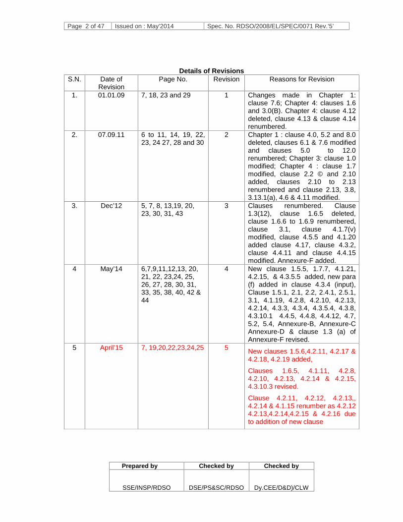
Details of RevisionsS.N. Date of
RevisionPage No. Revision Reasons for Revision
1. 01.01.09 7, 18, 23 and 29 1 Changes made in Chapter 1:clause 7.6; Chapter 4: clauses 1.6and 3.0(B). Chapter 4: clause 4.12deleted, clause 4.13 & clause 4.14renumbered.
2. 07.09.11 6 to 11, 14, 19, 22,23, 24 27, 28 and 30
2 Chapter 1 : clause 4.0, 5.2 and 8.0deleted, clauses 6.1 & 7.6 modifiedand clauses 5.0 to 12.0renumbered; Chapter 3: clause 1.0modified; Chapter 4 : clause 1.7modified, clause 2.2 © and 2.10added, clauses 2.10 to 2.13renumbered and clause 2.13, 3.8,3.13.1(a), 4.6 & 4.11 modified.
3. Dec’12 5, 7, 8, 13,19, 20,23, 30, 31, 43
3 Clauses renumbered. Clause1.3(12), clause 1.6.5 deleted,clause 1.6.6 to 1.6.9 renumbered,clause 3.1, clause 4.1.7(v)modified, clause 4.5.5 and 4.1.20added clause 4.17, clause 4.3.2,clause 4.4.11 and clause 4.4.15modified. Annexure-F added.
4 May’14 6,7,9,11,12,13, 20,21, 22, 23,24, 25,26, 27, 28, 30, 31,33, 35, 38, 40, 42 &44
4 New clause 1.5.5, 1.7.7, 4.1.21,4.2.15, & 4.3.5.5 added, new para(f) added in clause 4.3.4 (input),Clause 1.5.1, 2.1, 2.2, 2.4.1, 2.5.1,3.1, 4.1.19, 4.2.8, 4.2.10, 4.2.13,4.2.14, 4.3.3, 4.3.4, 4.3.5.4, 4.3.8,4.3.10.1 4.4.5, 4.4.8, 4.4.12, 4.7,5.2, 5.4, Annexure-B, Annexure-CAnnexure-D & clause 1.3 (a) ofAnnexure-F revised.
5 April’15 7, 19,20,22,23,24,25 5 New clauses 1.5.6,4.2.11, 4.2.17 &4.2.18, 4.2.19 added,
Clauses 1.6.5, 4.1.11, 4.2.8,4.2.10, 4.2.13, 4.2.14 & 4.2.15,4.3.10.3 revised.
Clause 4.2.11, 4.2.12, 4.2.13,,4.2.14 & 4.1.15 renumber as 4.2.124.2.13,4.2.14,4.2.15 & 4.2.16 dueto addition of new clause

Page 3 of 47 Issued on : ……….’2015 Spec. No. RDSO/2008/EL/SPEC/0071 Rev.’5’
Prepared by Checked by Checked by
SSE/INSP/RDSO DSE/PS&SC/RDSO Dy CEE/D&D)/CLW
CONTENTS
CHAPTER 1 GENERAL DESCRIPTION ANDSUPPLIER’S RESPONSIBILITIES
PAGE - 4
CHAPTER 2 OPERATING & SERVICE CONDITIONSAND DESIGN CONSTRAINTS
PAGE - 11
CHAPTER 3 PERFORMANCE REQUIREMENTS PAGE - 13
CHAPTER 4 TECHNICAL REQUIREMENTS PAGE - 18
CHAPTER 5 INSPECTIONS, TESTS AND TRIALS PAGE - 35
ANNEXURE A DESIGN DATA, CALCULATIONS AND DRAWINGSTO BE SUBMITTED BY SUPPLIER
PAGE - 37
ANNEXURE B DETAILS OF TRANSFORMER AND TRACTIONMOTOR
PAGE - 38
ANNEXURE C LOAD ON AUXILIARY CONVERTER PAGE - 40
ANNEXURE D INTERCONNECTION OF VCU WITH TRACTIONAND AUXILIARY CONVERTER
PAGE - 42
ANNEXURE E BURN IN TEST CYCLE PAGE - 43
ANNEXURE F MODES OF OPERATION AND FUNCTINALITY OFTHE LOCOMOTIVE
PAGE - 44

Page 4 of 47 Issued on : ……….’2015 Spec. No. RDSO/2008/EL/SPEC/0071 Rev.’5’
Prepared by Checked by Checked by
SSE/INSP/RDSO DSE/PS&SC/RDSO Dy CEE/D&D)/CLW
CHAPTER 1
GENERAL DESCRIPTION AND SUPPLIER’S RESPONSIBILITIES
1.1 Introduction1.1.1 Indian Railways (IR) is currently manufacturing electric locomotives employing 3-phase
propulsion based on the GTO technology. In order to upgrade the existing technology tothe present state-of-the-art, it is proposed to introduce electrics with three phase driveIGBT propulsion for fitment on WAG9 / WAG9H/WAP7 locomotive.
1.1.2 These propulsion equipments shall be provided by the Supplier inWAG9/WAG9H/WAP7 locomotives fitted with brake system and other equipment atCLW, Chittaranjan.
1.1.3 This specification defines the technical requirements of design, development,manufacture, testing, supply, delivery and commissioning of IGBT based 3-phasepropulsion equipments comprising of traction converter, auxiliary converter, vehiclecontrol unit (VCU) and their interconnections including documentation etc. for assemblyon WAG9/WAG9H/WAP7 locomotives of Indian Railways. The performancerequirements, environmental & service conditions, technical requirements andinspection, tests and trials are specified in the following chapters of this specification.The existing three phase Traction Motors 6FRA 6068 and the existing Transformer LOT6500/LOT 7500 shall be retained for WAG9/WAG9H/WAP7 locomotives. Two seriesresonant chokes available in the existing transformer also are to be used. The details ofTransformers and Traction Motors are given in Annexure B. Use of the existing chokehas to be mandatory since transformer is to be retained.
1.1.4 The design and manufacture of equipment shall be based on sound, proven andreliable engineering practice. The equipment used in different sub-systems shall be ofproven technology and design.
1.1.5 The specification envisages for design, development, manufacture, testing, supplydelivery and commissioning of IGBT based 3-phase propulsion system consisting oftraction converter, auxiliary converter, and control electronics (Vehicle control unit).
1.1.6 The Supplier has responsibility of engineering adaptation of the equipment and systemintegration of the locomotives.
1.1.7 The existing equipment layout in the machine room shall be studied by the Supplier.Traction converter, Auxiliary converter and Control electronics (Vehicle Control Unit)shall fit in existing locations of these equipments. Present mechanical drawings can beobtained from CLW/Chittaranjan.
1.2. Abbreviations and Definitions‘IR’ means Indian Railways
‘RDSO’ means Research Designs & Standards Organisation
‘Engineer’ means RDSO, Ministry of Railways
‘CLW’ means Chittaranjan Locomotive Works
‘Tenderer’ means Firm/companies participating in the tender
‘Supplier’ means the person, firm or Company with whom the order for supply of thework has been placed.
Page 5 of 47 Issued on : ……….’2015 Spec. No. RDSO/2008/EL/SPEC/0071 Rev.’5’
Prepared by Checked by Checked by
SSE/INSP/RDSO DSE/PS&SC/RDSO Dy CEE/D&D)/CLW
‘Sub Supplier’ means any person, firm or company from whom the Supplier may obtainany materials or fittings to be used for the works
‘Purchaser’ means the President of the Republic of India as represented by theRailways organisation entering into the contract.
‘Inspecting Officer’ means person, firm or department nominated to inspect thelocomotive or the representative of the inspecting officer so nominated
‘OEM’ means Original Equipment Manufacturer
‘BG’ means 1676 mm Broad Gauge used in IR
‘IS’ means Indian Standard
‘IRS’ means Indian Railways Standard
‘IEC’ means International Electrotechnical Commission
‘IEEE’ means Institution of Electrical and Electronics Engineers
‘UIC’ means Union International des Chemins de fer (International Union of Railways)
‘ORE’ means Office of Research and Experiment if the ‘UIC’
‘ISO’ means International Standards Organisation
1.3 References to Various Standards:
This Specification is based on the following Normative References and standards
1. IEC-61287 : Electronic Power Converter mounted on board rolling stock.
2. IEC-60571 : Specific rules concerning the electronic control part ofconverters.
3. IEC – 60349 –2 : Electronic converter fed alternating current motors
4. IEC-60563 : Permissible limiting temperature in services for component ofelectrical equipment of traction vehicles.
5. IEC –60505 : Guide for the evaluation and identification of insulation systemsof electrical equipment.
6. IEC –61375-1 : Electric Railway Equipment-Train Communication Network.
7. EN 50121-3-2 : Railway applications – Electromagnetic compatibility – Part 3-2 :Rolling stock – Apparatus.
8. EN 50121-2 : Railway applications – Electromagnetic compatibility – Part 2 :Emission of the whole railway system to the outside world.
9. IS 3231 : Relays and Contactors
10. IEC 228, IS 10810 : Cables
11. IEC 61373 : Railway applications – Rolling stock equipment – shock andvibration test
12. IEC 61377-3 : Combined testing of alternative current motors, fed by anindirect convertor, and their control system
13. IEC 60077–1 : Electric equipment for rolling stock – General service conditionsand general rules
Page 6 of 47 Issued on : ……….’2015 Spec. No. RDSO/2008/EL/SPEC/0071 Rev.’5’
Prepared by Checked by Checked by
SSE/INSP/RDSO DSE/PS&SC/RDSO Dy CEE/D&D)/CLW
14. IEC 60077–2 : Electric equipment for rolling stock – Electro technicalcomponents - general rules
15. IEC 61131 : Programming languages for PLC
16. EN 50153 : Railway application – Rolling Stock – Protective action againstelectrical hazards
17. EN 60529 : Protection classes of cases (IP code)
1.4 Submission of offers
1.4.1 Tenderer is required to offer clause-by-clause comments to this specification eitherconfirming acceptance of the clause and elaborating in detail where necessary orindicating deviations there from. The Tenderer shall be specific about deviationsrequired by them.
1.5 Scope of supply
1.5.1 The propulsion system to be supplied consists of following equipments:
IGBT based Traction Converter / Inverter IGBT based Auxiliary Converter / Inverter Cooling system Control, communication and protection system, including sensors & transducers Driver display unit and Interface of the system with driver display unit in each cab. Interface with other equipment not in the scope of the supply of this specification
such as brake system, speedometer. Apparatus / arrangement for ensuring safety of the operating and maintenance
personnel Traction motor speed sensors Source code and compiler of software of traction converter, auxiliary converter and
Vehicle Control Unit (VCU)OR
Supplier shall provide long term life time support for softwaremodification/upgradation as required by I.R. free of cost. An undertaking to thiseffect shall be furnished at the time of submission of tender document.
1.5.2 Commissioning of above equipments in WAG9/WAG9H/WAP7 locomotives.
1.5.3 The scope of supply shall also extend to the following:
1.5.3.1 Detailed design documents, drawings and calculations of the propulsion equipment.These shall be used for approval of design (see clause 1.7 of this specification).
1.5.3.2 Support material associated with the operation and maintenance of the equipments.The full documentation shall include Maintenance Manuals, Operation Manuals,Troubleshooting Directory, Training Manuals, QA documentation etc.
1.5.3.3 Complete know-how for assembly, testing and commissioning of the equipment on thelocomotive shall be transferred to IR at CLW. The engineering know how shall includeassembly / testing / commissioning process details, requisite drawings, training of staff,and maintenance instructions. These are required in order to enable series productionof such IGBT based WAG9/ WAG9H / WAP7 locomotives at CLW/Chittaranjan infuture.

Page 7 of 47 Issued on : ……….’2015 Spec. No. RDSO/2008/EL/SPEC/0071 Rev.’5’
Prepared by Checked by Checked by
SSE/INSP/RDSO DSE/PS&SC/RDSO Dy CEE/D&D)/CLW
1.5.3.4 One set of special tools, jigs & fixtures, special test equipment etc. for assembly,testing, commissioning, maintenance and operation of propulsion system, along withdocumentation, specification and purchase information thereof.
1.5.3.5 Suitable software tool and laptops (one laptop per propulsion system) as per clause4.4.8 and 4.4.9 of this specification.
1.5.3.6 Application software package required interacting with the Vehicle Electronics and forchanges in locomotive software operating parameters (like preset values, limits,characteristics etc. and behaviour of the locomotive in general) and other functions asper clause 4.4.10 of this specification.
1.5.3.7 One Off-loco test equipment for electronics as per clause 4.4.14 of this specification
1.5.4 The existing HB1/HB2, SB1/SB2 and Filter Cubicle shall be retained. Necessaryinterface of propulsion equipments with these cubicles have to be provided by theSupplier.
1.5.5 One set of spares of each type of module like power supply modules, IGBT modules,gate driver units, electronic cards and sensors of each type for at least one PropulsionSystem and thereafter one set of aforesaid spares for every 10 loco sets of PropulsionSystem.
1.5.6 One Lifting jig per 10 loco sets of propulsion system or part there of shall be supplied fortraction converter and Auxiliary Converter. One no. pump for filling coolant in tractionconverter shall be supplied per 10 loco set or part thereof.
1.6 Supplier’s ResponsibilitiesIn addition to the requirements spelt out elsewhere in this specification, the Supplier’sresponsibility shall also include the following:
1.6.1 The Supplier is expected to study the existing design, drawing and layout ofWAG9/WAG9H/WAP7 locomotives. The drawings can be obtained from ChittaranjanLocomotive works, Chittaranjan. Wherever the supplied equipment has to mechanicallyinterface with the existing equipment, requisite matching shall be ensured.
1.6.2 The Supplier shall arrange required instrumentation and carry out detailed tests andfield trials jointly with RDSO. The Supplier shall ensure availability of tools, testingequipment, measuring instruments & spare parts in adequate quantity for tests and fieldtrials.
1.6.3 The Supplier shall be entirely responsible for the supply and commissioning ofpropulsion system in accordance with the requirements of this specification.
1.6.4 The supply against this contract shall be designed in accordance with the specificationand the Supplier’s technical proposal for the satisfactory performance of the stock inservice notwithstanding any approval which the Engineer or the Inspecting officer mayhave given:
i) to the detailed drawings prepared by the Suppliers,
ii) of a Sub Supplier for material,
iii) of other parts of the work,
iv) of the tests carried out by the Supplier, Engineer or Inspection Officer.
1.6.5 . After successful commissioning in one of the WAG9/WAG9H/WAP7 locomotive, firstset of equipment shall be subjected to tests as per clause 5.1 of this specification.There after the equipments shall be subjected to Service Trials for a minimum 50000Kms as per clause 5.7 of this specification. The further supply of the propulsion system

Page 8 of 47 Issued on : ……….’2015 Spec. No. RDSO/2008/EL/SPEC/0071 Rev.’5’
Prepared by Checked by Checked by
SSE/INSP/RDSO DSE/PS&SC/RDSO Dy CEE/D&D)/CLW
shall start after successful completion of service trials. During the prototype tests/trialsor services, if any problem is observed or feed-back information is obtained, whichwarrants a re-check of the design / manufacture / quality of the equipment andcomponents, necessary action shall be taken by the Supplier to carry out the requiredinvestigations and to incorporate the modifications / improvements considered mostappropriate to comply with the specification & to ensure better reliability andperformance without any extra costs to the Purchaser. The Supplier shall not proceedwith any modifications / improvements unless approved by RDSO. Such modifications /improvements shall be carried out in all locomotives and shall be evaluated for theirvalidity for a further period of time as may be agreed mutually in each case.
1.6.6 For the equipment supplied / arranged by the Supplier, modifications mutually agreed tocomply with the specification shall be incorporated by the Supplier at his own cost in thelocomotives in a manner approved by the Purchaser. Drawings incorporating themodifications found necessary as a result of test and trial shall be submitted to RDSOfor approval before carrying out the modifications.
1.6.7 The Supplier shall further, notwithstanding any exercise by the Inspecting Officer of thepower of superintendence, be responsible for the sufficiency of the packing, markingetc. of all imported parts of the work to ensure their delivery in India without damage.
1.6.8 Training: The Supplier shall arrange for the training of CLW, RDSO and themaintenance & operating personnel of IR of 20 man months at supplier’s premises,where each man month shall be of 25 working man days. The cost of training shall beincluded in the offer. The details of the training shall be worked out during contractfinalisation stage/design approval stage.
1.7 APPROVAL OF DESIGN
1.7.1 The design shall be developed based on the requirements given in this specification andsound engineering practices. The design shall be developed in SI units.
1.7.2 The entire design shall be supplied by the Supplier with required technical data andcalculations to RDSO for approval. The manufacturing shall commence after and asper the approval of design by RDSO. Three sets of RDSO approved design are to besupplied by the Supplier. The actual distribution shall be finalised during design stage.
1.7.3 Programme of design & drawing submission shall be furnished with the tender to enableRDSO to plan in advance. Programme shall be finalized at the time of contractfinalization.
1.7.4 The Supplier shall submit all necessary data, designs, calculations, drawings andspecifications referred in their drawings or design documents in English language asrequired by RDSO for examination and shall provide explanation and clarification of thedocuments for which approval is sought. Approval or decision by RDSO shall normallybe given within 3 weeks of submission of all clarifications by the Supplier to thesatisfaction of RDSO. For the purpose, the Supplier shall depute its technical experts toRDSO for design discussions and finalisation. After the final design is approved theSupplier shall furnish complete set of specifications and standards as mentioned in theapproved drawings & documents and shall also submit the list of equivalent IndianStandards, wherever applicable.
1.7.5 Supplier shall submit complete design details, block diagrams, functional description ofall sub-systems, schematic drawings, loading calculations, circuits, wiring diagrams,
Page 9 of 47 Issued on : ……….’2015 Spec. No. RDSO/2008/EL/SPEC/0071 Rev.’5’
Prepared by Checked by Checked by
SSE/INSP/RDSO DSE/PS&SC/RDSO Dy CEE/D&D)/CLW
device rating & data sheets of converter, inverter and other power, control and the majorequipment, loading of electronic equipment /components calculated under the ambientconditions as specified, ventilation design, component rating etc. The aspects coveredabove are not exhaustive and the Supplier shall commit to supply / furnish completetechnical details with respect to their system and equipment design and to thesatisfaction of RDSO for design approval.
1.7.6 Supplier shall enclose details of their system design, weight particulars and itsdisposition covering all items, viz, Converter/Inverter, Auxiliary Converter, controlsystem etc. basic software specification, electronics, communication protocols, displaysystems, and any other aspect / equipment which is within the scope of supply of theSupplier. The Supplier shall also submit in their offer the simulated values of themaximum interference currents in the power supply. Supplier shall refer to Annexure Awhile enclosing the details.
1.7.7 A documentation giving description of design aspect for controlling emission andimmunity, test methodology and test plan as per EN 50238 & EN-50121 standards shallbe submitted to RDSO for approval.
1.7.8 Deviations proposed by the Supplier in the interest of reliability and better performanceshall be examined by RDSO in close consultation and association with the manufacturerso as to arrive at the final locomotive design.
1.7.9 The Supplier shall submit the complete material / technical specification and sources ofthe components during design approval. The specification shall specifically be indicatedon relevant drawings / documents.
1.7.10 The Supplier shall furnish details of its Quality Assurance and Quality Control at thedesign approval stage. The quality checks to be made at various stages of manufacture,final assembly and commissioning with tolerance would be indicated. The system wouldalso cover the quality assurance for bought out items.
1.7.11 Approval of design means the approval of general design features. Notwithstandingapproval from RDSO the Supplier shall be wholly and completely responsible for thesatisfactory performance of the equipment.
1.7.12 The Supplier shall be responsible for carrying out improvements and modifications at hisown expense on all the equipment supplied, provided such modifications/improvementsare decided to be necessary for meeting the requirements of reliability, performance,safety etc. jointly between Supplier and Purchaser.
1.7.13 For the purpose of technical decisions on improvements/modifications etc. onequipment, the final authority from the Purchaser’s side shall be RDSO.
1.8 STANDARD SPECIFICATIONS
International Electro-Technical Commission (IEC) publications and Indian Standards(IS) as far as applicable and relevant to the various equipment, systems and sub-systems shall be considered. The standards applicable for equipment as well as formaterials shall be furnished during design approval stage. In case of any conflictbetween the requirements of this specification and standards, the stipulations of thisspecification shall have precedence. In case of contradictions between thesestandards, the same shall be agreed mutually. Any deviations from these specifications

Page 10 of 47 Issued on : ……….’2015 Spec. No. RDSO/2008/EL/SPEC/0071 Rev.’5’
Prepared by Checked by Checked by
SSE/INSP/RDSO DSE/PS&SC/RDSO Dy CEE/D&D)/CLW
as specified herein and as may be mutually agreed to subsequently between theSupplier and RDSO shall not reduce reliability or decrease safety margins.
1.9 DOCUMENTATION
1.9.1 The Supplier shall furnish as made drawings and tracings, manual of instructions foroperation and maintenance of the equipments, trouble shooting instructions and suchother technical information as may be required for the maintenance and operation of theequipments in India. A preliminary version shall be supplied along with the despatch ofthe first equipments from the Supplier’s works. Final documentation shall be providedincorporating experience gained in final manufacturing phase and the first period oftrials within 6 months after completion of these trials.
1.9.2 Operation Manual
The operation manual shall be comprehensive, easy to read & understand and shallinclude the Trouble Shooting Instruction, the equipment ratings & operating limits ofinstalled system and control & safety features.
1.9.3 Maintenance Manual
The maintenance manuals shall include details of the various systems and sub-systemfrom a maintenance and fault finding stand point, with particulars of operatingparameters, tools for dismantling and testing methods of assembly and disassemblytolerances, repair techniques, lubrication details, software details and trouble shootingtools and all other information necessary to set up repair and servicing programme.Those shall be accompanied by suitable illustrations & diagram. It shall includeinspection / overhaul procedure and periodicity of various inspection / overhaulschedules in detail, including the tools, special tools / plants, and facilities required. Anillustrated parts catalogue with sufficient information to identify and requisition any partshall be included.
1.9.4 Clarification and amendments to the document, particularly operations andmaintenance manual, as necessary during the defect liability period shall be supplied bythe Supplier. Updates shall be provided for the original and all copies supplied.
1.9.5 The operations & maintenance manuals shall be supplied @ 1 set (hard copies) perequipment. All the document shall be supplied in electronic form on Compact Discs /DVD also along with software and hardware tools to read and print them. The manualshall be generally in A4 size and shall be bound with wear resistant covers.
1.10 INFRINGEMENT OF PATENT RIGHTSIndian Railway shall not be responsible for infringement of patent rights arising due tosimilarity in design, manufacturing process, components used in design, developmentand manufacturing of propulsion system and any other factor which may be a causesuch dispute. The responsibility to settle any issue lies with the manufacturer.
*************************

Page 11 of 47 Issued on : ……….’2015 Spec. No. RDSO/2008/EL/SPEC/0071 Rev.’5’
Prepared by Checked by Checked by
SSE/INSP/RDSO DSE/PS&SC/RDSO Dy CEE/D&D)/CLW
CHAPTER - 2
OPERATING & SERVICE CONDITIONS AND DESIGN CONSTRAINTS
2.1 Leading parameters of Locomotive:
Parameter WAG9 locomotive WAG9H locomotive WAP7 locomotiveAxle load 20.5 tonnes ± 2% 22.0 tonnes
± 2%20.5 tonnes ± 2%
No. of axles 6 6 6
Weight 123 tonnes ± 1% 132 tonnes ± 1% 123 tonnes ± 1%
Max. design speed 100 kmph 100 kmph 140 kmph
Test speed 110 kmph 110 kmph 155 kmph
2.2 Power Supply System:
Nominal supply voltage 25 kV, 50 Hz, single phase, AC
Normal variation in supply voltage 19 kV to 27.5 kV
Occasional maximum voltage 31 kV
Occasional minimum voltage 16.5 kV
Variation in supply frequency ± 8% (46 to 54 Hz)
2.3 Climatic and Environmental Conditions:
Atmospherictemperature
Under Sun : 75°C max.In shade : 55°C max.Temp. inside working locomotive may reach 60°C.Minimum temperature: -5°C
Humidity 100% saturation during rainy season. Reference site
conditionsi) Ambient Temp.: 50°Cii) Temp. inside loco: 60°Ciii) Humidity: 100%iv) Altitude: 1776 m above mean sea level.
Rain fall Very heavy in certain areas. Atmosphere
during hotweather
Extremely dusty and desert terrain in certain areas. The dustconcentration in air may reach a high value of 1.6 mg/m3. Inmany iron ore and coalmine areas, the dust concentration isvery high affecting the filter and air ventilation system.
Coastal area Locomotive and equipment shall be designed to work in coastalareas in humid and salt laden atmosphere with maximum pHvalue of 8.5, sulphate of 7 mg per litre, max. concentration ofchlorine 6 mg per litre and maximum conductivity of 130 microsiemens /CM
Vibration High level of vibration and shocks. Electromagnetic High degree of electromagnetic pollution is anticipated in

Page 12 of 47 Issued on : ……….’2015 Spec. No. RDSO/2008/EL/SPEC/0071 Rev.’5’
Prepared by Checked by Checked by
SSE/INSP/RDSO DSE/PS&SC/RDSO Dy CEE/D&D)/CLW
Pollution locomotive machine room, where the equipment shall bemounted. Necessary precaution shall be taken in this regard.
The equipment shall be able to start up at the maximum temperature, which may bereached inside a locomotive standing in sun, without any requirement of pre-cooling ofelectronic equipment.
2.4 Interferences:
2.4.1 The electric and electronic apparatus used in propulsion system shall comply emissionand immunity aspects of EMC to CENELEC standard EN 50238 and EN-50121. Theinternal EMC shall cover a combination of earthing, shielding and isolation ofinterference sources so that conducted and radiated noises are properly segregated orsuppressed and no other equipment is affected due to operation of propulsionequipments.
2.4.2 The tracks over which the offered locomotive propulsion system shall work shall beequipped with DC track circuits, 83-1/3 Hz track circuits as well as track circuits athigher frequencies. Similarly, other devices like axle counters, block instruments, pointmachines, etc., shall also be employed. On the communication network, controlcircuits, teleprinter circuits, as well as VHF/UHF and micro-wave circuits are employed.
2.4.3 The harmonic currents injected in the overhead supply system (as also the track returncurrent) can introduce voltage harmonics on power supply and can interfere with signaland telecom circuits. The design of the power electronics and control electronicsprovided on the propulsion system shall be such as not to cause levels of interferenceexceeding the levels specified below at any point in the operating envelope of thelocomotive:
Psophometric current 10.0 A
DC component 4.7 A
2nd Harmonic component(100 Hz) 8.5 A
1400 Hz to 5000 Hz 400 mA
More than 5000 Hz up to 50000 Hz 270 mA
2.5 Weight and layout particulars
2.5.1 Weights of the existing major equipment are as follows:
Traction Converter / Inverter (2 nos.) : 3330 kg each
Auxiliary Converter ( 3 nos. in 2 boxes) : 608 kg (box1) + 1130 kg (box2)
Control cubicle SB1 & SB2 incl. control electronics : 160 kg + 170 kg = 330 kg
Weights of equipment to be fitted in the locomotive have to be considered tomake sure the final locomotive weight remains as per stipulation in thisspecification.
***********************

Page 13 of 47 Issued on : May’2014 Spec. No. RDSO/2008/EL/SPEC/0071 Rev.’5’
Prepared by Checked by Checked by
SSE/INSP/RDSO DSE/PS&SC/RDSO Dy.CEE/D&D)/CLW
CHAPTER 3
PERFORMANCE REQUIREMENTS
3.1 Performance: At 22.5 kV line voltage and half worn wheels, locomotive fitted with thepropulsion equipment shall be capable of the following performance under the referencesite conditions. Full traction power shall be available in the voltage range of 22.5 kV to28.5 kV. Variation in traction power beyond 22.5 kV – 28.5kV shall be indicated in thedesign details.
Parameter WAG9 locomotive WAG9Hlocomotive
WAP7 locomotive
(i) Startingtractive effortunder dry railcondition
Not less than 460 kN Not less than 500kN
Not less than 322.6kN
(ii) Continuousrated speed
Not more than 50kmph
Not more than 50kmph
Not more than 70kmph
(iii) Max. designspeed
100 kmph 100 kmph 140 kmph
(iv) Continuousrated power atrail
Not less than 4500kW at all speedsfrom continuousspeed to max.design speed
Not less than 4500kW at all speedsfrom continuousspeed to max.design speed
Not less than 4500kW at all speedsfrom continuousspeed to max.design speed
(v) Regenerativebrake
Maximum possible without skidding over full speed range but notless than 260 KN.

Page 14 of 47 Issued on : ……….’2015 Spec. No. RDSO/2008/EL/SPEC/0071 Rev.’5’
Prepared by Checked by Checked by
SSE/INSP/RDSO DSE/PS&SC/RDSO Dy CEE/D&D)/CLW
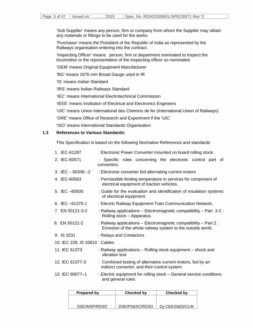
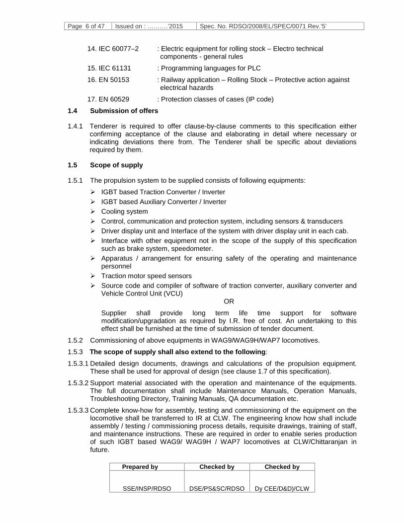
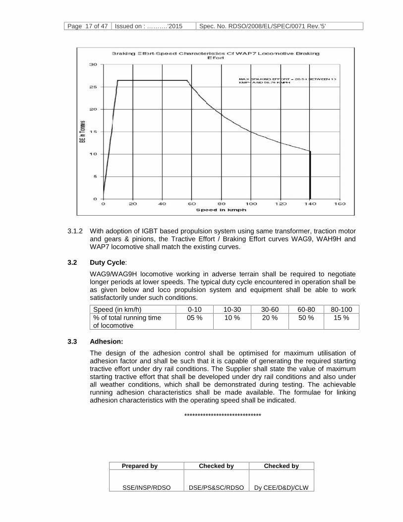
3.1.1 The present characteristics of WAG9, WAG9H and WAP7 locomotive with GTO basedpropulsion are given below :
Page 15 of 47 Issued on : ……….’2015 Spec. No. RDSO/2008/EL/SPEC/0071 Rev.’5’
Prepared by Checked by Checked by
SSE/INSP/RDSO DSE/PS&SC/RDSO Dy CEE/D&D)/CLW

Page 16 of 47 Issued on : ……….’2015 Spec. No. RDSO/2008/EL/SPEC/0071 Rev.’5’
Prepared by Checked by Checked by
SSE/INSP/RDSO DSE/PS&SC/RDSO Dy CEE/D&D)/CLW
Page 17 of 47 Issued on : ……….’2015 Spec. No. RDSO/2008/EL/SPEC/0071 Rev.’5’
Prepared by Checked by Checked by
SSE/INSP/RDSO DSE/PS&SC/RDSO Dy CEE/D&D)/CLW
3.1.2 With adoption of IGBT based propulsion system using same transformer, traction motorand gears & pinions, the Tractive Effort / Braking Effort curves WAG9, WAH9H andWAP7 locomotive shall match the existing curves.
3.2 Duty Cycle:
WAG9/WAG9H locomotive working in adverse terrain shall be required to negotiatelonger periods at lower speeds. The typical duty cycle encountered in operation shall beas given below and loco propulsion system and equipment shall be able to worksatisfactorily under such conditions.
Speed (in km/h) 0-10 10-30 30-60 60-80 80-100% of total running timeof locomotive
05 % 10 % 20 % 50 % 15 %
3.3 Adhesion:The design of the adhesion control shall be optimised for maximum utilisation ofadhesion factor and shall be such that it is capable of generating the required startingtractive effort under dry rail conditions. The Supplier shall state the value of maximumstarting tractive effort that shall be developed under dry rail conditions and also underall weather conditions, which shall be demonstrated during testing. The achievablerunning adhesion characteristics shall be made available. The formulae for linkingadhesion characteristics with the operating speed shall be indicated.
*****************************

Page 18 of 47 Issued on : May’2014 Spec. No. RDSO/2008/EL/SPEC/0071 Rev.’5’
Prepared by Checked by Checked by
SSE/INSP/RDSO DSE/PS&SC/RDSO Dy.CEE/D&D)/CLW
CHAPTER 4
TECHNICAL REQUIREMENTS
4.1 GENERAL
4.1.1 The equipment shall be of proven state of the art technology that has beentried/tested in rail traction application with good level of performance and result. Thedetails of such applications and user experience shall be provided. Features to yieldhigh availability for traffic use, low maintenance requirements, easy maintainability,high reliability in operation and high efficiency shall be incorporated.
4.1.2 The system and equipment shall be specially adopted for application to meet theperformance requirements under environmental conditions specified in Chapter 2 & 3of this specification. Adequate margin shall be built in the design, particularly to takecare of condition of high ambient temperatures, dusty condition, high humidityprevailing in India. The equipment, sub-system and their mounting arrangement shallbe designed to withstand satisfactorily vibrations and shocks encountered in serviceas specification in relevant IEC publications unless otherwise prescribed.
4.1.3 Easy access for inspection and maintenance requiring minimum attention shall begiven special consideration in the design and layout.
4.1.4 It shall be possible to use the locomotive in multiple unit operation up to 02locomotives in one group. The entire control of both locomotives shall be achievedfrom the leading locomotive under multiple locomotive operations.
4.1.5 Provision shall be made in the control circuitry of the locomotive, to limit the startingtractive effort to predefined values when required during operation. The predefinedvalues shall be around 30 ton per locomotive, to be decided during design stage.
4.1.6 Provision shall be made to enable operation of locomotive under inching control modeat a constant speed settable by the driver in steps of 0.1 Kmph, in the range 0.5Kmph to 1.5 kmph in yards for a load not greater than 5200 tonnes and on a gradientof 1 in 1000 or flatter. It shall be possible to change from inching control mode toNormal Mode and vice versa by the driver depending upon his requirement.Provision shall also be made to enable operation of locomotive in shunting mode upto 15 kmph in yards for a load not greater than 5200 tonnes and on a gradient of 1 in1000 or flatter.
4.1.7 Adequate redundancy shall be built in with the design in order to improve reliabilityand availability. In the vital units of the power control circuit, where any defect/failureof a component would cause complete failure of locomotive’s electrical system,suitable redundancy/duplication shall be provided preferably with automaticsubstitution features to avoid locomotive failure or drastic reduction in performancedue to such defects. The power supplies to the control circuit shall be hot redundant.The redundancy requirements are given in following paragraph.
No single-point failure of the propulsion system shall cause the complete failure of thelocomotives and the number of single point failures which would result in a loss ofmore than 1/6th (one sixth) of the traction power shall be minimised. The Suppliershall identify and advise the Purchaser of any single-point failures that shall cause a
Page 19 of 47 Issued on : ……….’2015 Spec. No. RDSO/2008/EL/SPEC/0071 Rev.’5’
Prepared by Checked by Checked by
SSE/INSP/RDSO DSE/PS&SC/RDSO Dy CEE/D&D)/CLW
loss of power of 1/6th (one sixth) or greater of the traction power as part of the designdetails.
In the event of breakdown of any component or basic unit of equipment, it shall bepossible to continue to haul the train with the least reduction possible in its services,operating within restricted but permissible conditions. The basic principles andprocedures to be followed in the event of a breakdown shall be:
i) Breakdown of drive side converter of traction converter (except for shortcircuit of IGBTs) or electrical failure of traction motor: The power of thelocomotive shall be reduced only by 1/6 (one sixth).
ii) Breakdown of line side converter of traction converter (except for short circuitof IGBTs): The power of the locomotive shall be reduced only by 1/4 (onefourth).
iii) Failure of drive controller unit or power supply of the drive controller unit orgate unit or gate unit power supply of a drive side converter of tractionconverter: The power of the locomotive shall only be reduced by 1/6 (onesixth).
iv) Failure of drive controller unit or power supply of the drive controller unit orgate unit or gate unit power supply of line side converter of traction converter:The power of the locomotive shall be reduced only by 1/4 (one fourth).
v) Failure of one speed sensor element: The operation of the locomotive shall notbe degraded and all traction motors shall remain operational.
vi) Breakdown of an auxiliary converter: The traction capacity of the locomotiveshall not be affected as a result of the redundant design of the auxiliaryconverters.
vii) Control Electronics (VCU) shall have adequate redundancy so that abreakdown shall not affect the traction and braking operations of locomotive.
4.1.8 The protection/alarm/indication circuits shall normally have self-correcting featuresrather than cause tripping of the locomotive or drastic reduction in tractive effort. IfDriver’s intervention is needed, sufficient time/advance indication shall be madeavailable to the Driver to enable corrective action to be taken in time.
4.1.9 In design and construction, reliability and maintainability shall be of paramountconsideration. Supplier shall submit reliability calculations indicating MTBF fordifferent devices, cards and sub-assemblies during design stage. Adequate marginshall be provided to take into account ambient conditions prevailing in India.
4.1.10 High efficiency of equipment shall be important consideration, next only to highreliability. The components and technology used shall ensure very high efficiency ofthe converter. Tenderer shall furnish the expected efficiency with respect to vehicleload and speeds The Tenderer shall specify the efficiency of individual equipmentsuch as Traction Converter and Auxiliary Converter. These measurements ofefficiencies shall have to be organised by the Supplier at their cost and shall bewitnessed by IR’s representative.
4.1.11 Modular constructions shall be adopted wherever considered possible. Easy accessfor inspection/maintenance and minimum maintenance requirement shall be givenspecial consideration in design and layout. Traction Converter shall be designed insuch a way that main Transformer bushings are visible after opening of Traction

Page 20 of 47 Issued on : ……….’2015 Spec. No. RDSO/2008/EL/SPEC/0071 Rev.’5’
Prepared by Checked by Checked by
SSE/INSP/RDSO DSE/PS&SC/RDSO Dy CEE/D&D)/CLW
Converter front door to check any oil leakage from bushing. In this reference, thescheduled maintenance activities shall be a part of design documents and have to begot approved along with design approval.
4.1.12 In the design and construction of IGBT based converter/inverter and associatedcontrol equipments, adequate margin shall be provided to taken into accountconditions prevailing in India. Freedom from dust and protection from surges shall beensured. Modular construction shall be adopted wherever considered possible forachieving the above requirements.
4.1.13 The voltage rating of IGBT would be so chosen that at least 25% margin is availableafter taking into consideration the DC link voltage and voltage jump on account ofinductance and capacitances in the circuit. The current rating of IGBT shall be suchthat the junction temperature has the minimum thermal margin of 10ºC in the worstloading conditions and under the ambient conditions as specified.
4.1.14 The design calculations of worst case temperature rise of equipment shall be madeafter taking into account 25% choking of filters and heat sink/radiator fins. A safetymargin of at least 10ºC shall be kept with respect to maximum permissible junctiontemperature of power devices declared by the manufacturer.
4.1.15 The power equipment shall be designed and operated to achieve near unity powerfactor and minimum harmonic interference current from OHE. The input power factorshall be close to unity within the normal variation range of line voltage at all speeds ofoperation of the locomotive. The maximum interference current permitted is specifiedin chapter 2 of this specification. Pantograph bouncing normally experienced inservice shall not adversely affect the propulsion equipment.
4.1.16 The equipments for WAG9/WAG9H/WAP7 shall be identical in all respects.
4.1.17 Energy metering (energy consumption and energy regeneration) function shall beintegrated in the control software.
4.1.18 Marking: The major equipments / subassemblies shall bear marking and serialnumber. The equipment shall contain serial number and make of Supplier.
(a) All equipments / cubicles shall contain name plates of anodized aluminumwith engraved / punched letters.
(b) The inverter rating plate shall be marked with the following information:
(i) Type / Make
(ii) Contract number
(iii) Month and year of manufacture / batch no. / serial no.
(iv) Rating:
- kVA
- Input voltage range
- Output voltage, frequency and wave shape.
4.1.19 Pantograph bouncing up to 45 ms (limit of zero pressure contact) normallyexperienced in service shall not adversely affect the propulsion equipment.

Page 21 of 47 Issued on : ……….’2015 Spec. No. RDSO/2008/EL/SPEC/0071 Rev.’5’
Prepared by Checked by Checked by
SSE/INSP/RDSO DSE/PS&SC/RDSO Dy CEE/D&D)/CLW
4.1.20 The modes of operations and functionality of the locomotives are detailed in Annexure-F.
4.1.21 Any new systems may be planned to be commissioned on locomotive in future likeRadio Remote Control and Remote Diagnostic System. In such cases, supplier shallprovide full cooperation for adaptability of these systems with their Propulsion System.The cooperation shall include minor design changes, hardware modifications andsoftware changes without any extra cost to I.R.
4.2 Traction converter
4.2.1 There are two traction converters identical in all respects shall be provided in oneloco. The Supplier is expected to study in detail the existing interface of the GTOConverter with the remaining equipment on the locomotive (e.g. Traction Motor, itsspeed and Temperature Sensors, Transformer with its series resonant choke,Harmonic Filter, Cooling Arrangement and Vehicle Control Unit etc.). The Supplier isalso expected to study in detail the existing machine room layout, ducting, cablerouting etc. on the locomotive. Site visit for this purpose can be arranged on priorintimation to CLW. It shall be deemed that the Tenderer knows all the relevantaspects at the time of making offer.
4.2.2 Following special features shall be provided to maximise the performance & reliabilityand minimise possibilities of trains being stalled in the section:
(a) Individual axle control shall be provided.
(b) Suitable redundancy shall be provided in the vital PCBs connected with safetyand power supplies, so that locomotive failure, degradation in performance anddisabling the train is avoided in the event of their failure.
(c) The existing fault screen of the driver (fault messages displayed on driverdisplay) and DDS recording shall remain same as in existing GTO locomotiveswith the adoption of IGBT traction converter except for following new messagesneeded due to individual axle control:
Motor 1 – Bogie 1 isolated – reduced traction/braking Motor 2 – Bogie 1 isolated – reduced traction/braking Motor 3 – Bogie 1 isolated – reduced traction/braking Line converter 1 – Bogie 1 isolated – reduced traction/braking Line converter 2 – Bogie 1 isolated – reduced traction/braking Motor 1 – Bogie 2 isolated – reduced traction/braking Motor 2 – Bogie 2 isolated – reduced traction/braking Motor 3 – Bogie 2 isolated – reduced traction/braking Line converter 1 – Bogie 2 isolated – reduced traction/braking Line converter 2 – Bogie 2 isolated – reduced traction/braking
4.2.3 The wheel slip detection and correction system shall be an integral part of the controlsystem of the Power converters/inverter and shall supervise excessive acceleration,differential speeds between axles, over speed and any other parameter considerednecessary to maximize adhesion and minimize wheel slipping / skidding. Theadhesion control system shall be capable of giving high adhesion through a wheel slipcontrol system of proven performance. The objective shall be to maximise thedelivered draw bar pull through control system in conjunction with sanding.
Page 22 of 47 Issued on : ……….’2015 Spec. No. RDSO/2008/EL/SPEC/0071 Rev.’5’
Prepared by Checked by Checked by
SSE/INSP/RDSO DSE/PS&SC/RDSO Dy CEE/D&D)/CLW
4.2.4 The converter/inverter system shall be capable of withstanding the maximum shortcircuit current under fault conditions and these shall be established throughcalculations. The converter / inverter system shall also be designed to withstandextreme disturbances like short-circuit / open circuit etc. at all points of input / outputinterfaces with locomotive, without any failure. This shall be demonstrated duringprototype tests as per the relevant clause of the IEC.
4.2.5 During the earth fault or phase to phase fault in the traction motor, protection schemeof the converter/ inverter shall ensure that the fault does not have any adverse impacton the Performance of the converter/inverter. Details shall be furnished by theSupplier of such a scheme.
4.2.6 Only dry type capacitors shall be used for dc link / harmonic filter / resonant circuits.
4.2.7 Wheel diameter difference permissible shall be more than or equal to the presentlimits, which are as follows:
Wheels on different axles of the same bogie : 8.0 mm Wheels on axles of the different bogies : 25.0 mm
4.2.8 The proposed equipments shall not violate the given space envelopes of theequipment to be replaced. Any needed change due to new equipment has to bedemonstrated with the help of suitable drawings. The dimensions of the convertershall not exceed the existing foot print and no intermediate frame shall be allowed formounting of traction converter as a separate part of converter. IR intends to use DCcontactors inside the traction converter for isolation of individual traction motor infuture. This aspect may also be taken into consideration while designing theconverter.
Item Envelope Dimensions (WxDxH) mmIGBT converter with VCU interface andcooling pump.
3000x1100x2087
Cooling tower with water/air and oil/airexchanger
1450x1154x1510
Machine Room Blower 800x1100x1620
4.2.9 Existing principle of the machine room ventilation shall be kept unchanged.
4.2.10 Traction motor speed sensor and associated accessories:
(i) Active speed Sensors with 120 tooth wheel ring duly approved by RDSO/CLWshall be provided.
(ii) Power supply for the speed sensor shall be from the electronics card of theconverter. Presently 2 (two) shielded cables, each having single twisted pair areused in the loco machine room for speed sensor. Same arrangement of cableshall be retained.
Following shall be within the scope of supply of the Supplier:
Active speed sensor with existing mechanical interface.
Tooth wheel with existing mechanical interface.
Sensor plate.
Suitable male and female parts of the speed sensor connectors at the sensorplate.
The sensor connector at the converter end. Note: Speed sensor shall be supplied asper CLW specification No. CLW/ES/03/0528 dated Nov’.12 or latest which may be

Page 23 of 47 Issued on : ……….’2015 Spec. No. RDSO/2008/EL/SPEC/0071 Rev.’5’
Prepared by Checked by Checked by
SSE/INSP/RDSO DSE/PS&SC/RDSO Dy CEE/D&D)/CLW
taken from CLW. The drawing and details of location of speed sensor connectorsused presently in GTO converter may be had from CLW and location of speed sensorconnectors at converter shall be kept same as per the drawing to have same length ofcable for speed sensor.
4.2.11 Existing input power connection methodology from transformer terminal to tractionConverter terminal shall be used. Supplier shall use same transformer links andflexible links as per CLW specification no. CLW/ES/3/0138 or latest
4.2.12 Converter outputThe motor converter output current ripple shall be such as to keep the torquepulsations and traction motor heating to a minimum. It is the Supplier’s responsibilityto make sure that output quality of the Traction Converter is entirely suitable for theexisting traction motors. The motor converter shall generate the 3-phase output withhigher pulsating frequencies and improved pulse pattern than with the existing GTOsystem.
4.2.13 The existing transformer, which is to be used, is provided with a filter winding. Theresistance and inductance values of which have been given in Annexure B. The filterresistor and filter capacitor ratings are 2800 V, 0.2 ohm/40 kW & 0.2 ohm/60 kW and0.4 mF, 2500 V, 80 A (bank capacity) respectively. During single bogie operation, filteradaption contactor (8.2) is opened thereby introducing an additional resistance.During normal operation, contactor 8.2 remains closed. The existing harmonic filterhas to be considered while designing the system for interference limits. It is expectedthat with higher switching frequency of IGBT, this shall be sufficient to meet thestipulated harmonics requirements. It shall be possible to simplify the Harmonic Filter.The Tenderer shall indicate clearly the filter arrangement required, and if anymodifications are required, it has to be done through choosing appropriate externalRC elements, which shall then be provided to IR for necessary modification in thelocomotive.
4.2.14 Mechanical Dimensions:Dimensions of the existing Traction Converter are 3000 x 1100 x 2100 mm (WxDxH).The dimensions of the IGBT Traction shall not exceed these values. Detaileddimensional drawings can be made available to the Tenderer at CLW. The panelsheets used for fabrication of enclosure shall be of steel as per IRSM 41-97 ofminimum thickness 2.0 mm or more with corrosion resistance coating. The cabinetdoor material may be used aluminium alloy for light weight of the door. The quantity offixing bolt per door shall not be more than 10 nos. Necessary FEM analysis ofcabinet shall be submitted by supplier.
4.2.15 Cooling:The present GTO Converter uses forced oil cooling. There is a common aluminiumalloy heat exchanger module for both converter and transformer, but with different oilcircuits. The blower is common. There are two cooling units, one for each bogie.
The Supplier shall use the existing radiator and cooling circuit with blower and pumpsfor the cooling of the Traction Converter The coolant used for the converter shall bewater cooled (mixture of water and ethylene glycol containing corrosion inhibitors) andthe ratio of ethylene glycol and water shall be 30:70. The form and appearance ofcoolant shall be liquid green. Visibility of coolant level shall be provided inconservator of the converter and there shall be sufficient gap between maximum andminimum level. There shall also be a drain cock on the converter side to prevent

Page 24 of 47 Issued on : ……….’2015 Spec. No. RDSO/2008/EL/SPEC/0071 Rev.’5’
Prepared by Checked by Checked by
SSE/INSP/RDSO DSE/PS&SC/RDSO Dy CEE/D&D)/CLW
spillage of coolant. The detailed drawings of the existing system can be obtainedfrom CLW.
4.2.16 MCB in HB panels & Connectors in the converter side for 3-phase 415 V auxiliarysupply, i.e., for pump/fan etc, in the Propulsion System shall be in the firm’s scope ofsupply. Existing MCB of 16A in HB panel used in GTO based converter shall be onlybe used. MCBs within the power converter shall be avoided for protection of coolingpump. Standard cable length as in GTO loco shall be adopted for cooling pumpconnection. Details and drawings for location of pump connection point at converterside may be had from CLW.
4.2.17 Standard orientation of Traction Motors and standard sequence of motor terminals tobe adopted as in existing GTO based traction converters. The same configurationshall be used by CLW for the connections of Traction Motors. Supplier shall alsoadopt the standard lengths of the control cable as in case of GTO based converters.The details shall be obtained from CLW.
4.2.18 The initialization time for IGBT based Traction Converter shall be kept less than 30sec. Further, the total time for achieving node 504 shall be less than 50 sec.
4.2.19 Converter control electronics and IGBT modules enclosures shall comply with IP 54.
4.3 Auxiliary System:4.3.1 Auxiliary system shall consist of Auxiliary Converters, Battery Charger and associated
protection system. The Auxiliary system shall be galvanically isolated from the tractionpower system. Auxiliary system design shall ensure that there is no surge / spike inthe output voltage between phase to phase and with respect to earth. The commonmode output voltage (with respect to earth) shall be as low as possible, preferablyzero.
4.3.2 Auxiliary Converter shall be IGBT based and forced air-cooled. However thyristorscan be used on input side. The control shall be microprocessor / micro-controllerbased with diagnostic features. Protection from overload/short circuit, single phasingand any other protection considered necessary for reliable functioning shall beprovided. The output of Auxiliary converter shall be SINUSOIDAL.
4.3.3 Three Auxiliary converters (BUR1, BUR2 and BUR3) identical in all respects eachwith 130 kVA capacity and battery-charging unit (details in clause 4.3.4) shall beprovided in one loco.
4.3.4 Converter Ratings (BUR1, BUR2 & BUR3):
A INPUT
(a) Voltage : 1000V single phase 50 Hz at a catenaryvoltage of 25 kV. The catenary voltage canvary in the range as specified in clause 2.2of this specification.
(b) Frequency : 50 Hz ± 8%
(c) Power Factor : 0.8 or more (at full load) between OHEvoltage 19kV to 27.5kV and min. 0.55 above27.5 kV.
Page 25 of 47 Issued on : ……….’2015 Spec. No. RDSO/2008/EL/SPEC/0071 Rev.’5’
Prepared by Checked by Checked by
SSE/INSP/RDSO DSE/PS&SC/RDSO Dy CEE/D&D)/CLW
(d) Total Harmonic Distortion(Current)
: To be kept to minimum, manufacturer shallindicate the optimized value at full load.
(e) Winding Details : 334 kVA / 5.82% Impedance / 258.58 mΩ
(f) Other Details : A R-C snubber is placed across theauxiliary winding with R = 22 Ohm, 320Wand C = 0.66 micro Farad, 2000V. Inaddition, toroid cores are inserted in theinput cables to minimize the di/dt andinteraction between multiple convertersacross same winding. The tenderer has tostudy the present scheme and to ensurethat offered converter is protected in alloperating conditions.
B OUTPUT(i) SINUSOIDAL AC, 3 Phase
(a) AC Voltage (L-L) : 415 V ± 5%
(b) Nominal Output Frequency : 50 Hz ± 3%
(c) KVA output : 130 kVA
(d) Short time current rating : Same as overload rating of existing GTObased 3 x 100 kVA Auxiliary Converter.
(e) Total harmonic distortion(THD) in the output voltageto the 3-phase motor
: Less than 10%.
(f) dv / dt : Less than 500V/Microsecond
(g) The auxiliary converter shall be suitable for generating 3-phase AC output atmultiple voltages and frequencies as detailed in para 4.3.7 below
(ii) Nominal DC Output : 110V, 80A with current ripple less than 5%and voltage regulation ±5%, with batterycurrent maximum of 110A.
: The Battery Charger characteristics shall besuitable for charging the existing 199 AH Ni– Cd battery & supplying the 110V load in 3-phase locomotives.
Note: Rated capacity of 130 kVA is expected for input voltage range as specified in clause2.2 of this specification. However, degraded performance in terms of lower outputvoltage or frequency is acceptable below the range specified and manufacturer shallspecify the extent of degraded performance. It shall not be possible to regulate theduty cycle of the loads.
Page 26 of 47 Issued on : ……….’2015 Spec. No. RDSO/2008/EL/SPEC/0071 Rev.’5’
Prepared by Checked by Checked by
SSE/INSP/RDSO DSE/PS&SC/RDSO Dy CEE/D&D)/CLW
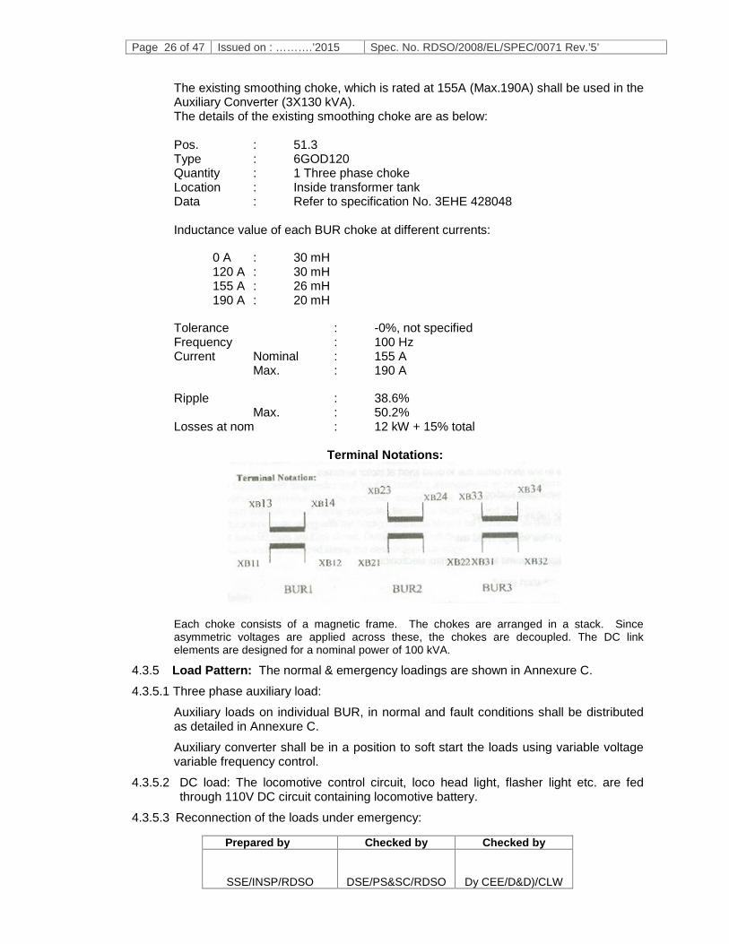
The existing smoothing choke, which is rated at 155A (Max.190A) shall be used in theAuxiliary Converter (3X130 kVA).The details of the existing smoothing choke are as below:
Pos. : 51.3Type : 6GOD120Quantity : 1 Three phase chokeLocation : Inside transformer tankData : Refer to specification No. 3EHE 428048
Inductance value of each BUR choke at different currents:
0 A : 30 mH120 A : 30 mH155 A : 26 mH190 A : 20 mH
Tolerance : -0%, not specifiedFrequency : 100 HzCurrent Nominal : 155 A
Max. : 190 A
Ripple : 38.6%Max. : 50.2%
Losses at nom : 12 kW + 15% total
Terminal Notations:
Each choke consists of a magnetic frame. The chokes are arranged in a stack. Sinceasymmetric voltages are applied across these, the chokes are decoupled. The DC linkelements are designed for a nominal power of 100 kVA.
4.3.5 Load Pattern: The normal & emergency loadings are shown in Annexure C.
4.3.5.1 Three phase auxiliary load:
Auxiliary loads on individual BUR, in normal and fault conditions shall be distributedas detailed in Annexure C.
Auxiliary converter shall be in a position to soft start the loads using variable voltagevariable frequency control.
4.3.5.2 DC load: The locomotive control circuit, loco head light, flasher light etc. are fedthrough 110V DC circuit containing locomotive battery.
4.3.5.3 Reconnection of the loads under emergency:

Page 27 of 47 Issued on : ……….’2015 Spec. No. RDSO/2008/EL/SPEC/0071 Rev.’5’
Prepared by Checked by Checked by
SSE/INSP/RDSO DSE/PS&SC/RDSO Dy CEE/D&D)/CLW
If one of the auxiliary converter fails then the provision is made for continuedoperation with reconnection of loads. The reconnection of loads is done with the helpof contactors with interlocking feature. See Annexure C for the proposed connection.These contactors are controlled by the vehicle control electronics. The necessaryactions for reconnection shall be taken by vehicle control electronics.
4.3.5.4 The auxiliary converter shall have provision for giving suitable supply for cab airconditioning, which may be adopted in future. The tenderer shall submit the completeproposal consisting of related hardware and software.
4.3.5.5 4.3.5.5 At present, TM Blowers start running upon closure of VCB and continue to run even ifTraction Motor temperature is not high & locomotive is at standstill. Energyoptimisation shall be done by supplier by running auxiliaries at various speeds throughsoftware/hardware by sensing temperature of traction motor and transformer. Furtherdetails shall be worked out by supplier in association with RDSO and CLW duringdetailed design stage.
4.3.6 Protection:4.3.6.1 The devices used in the inverter shall be protected against high rate of rise of voltage
& current, line transient surge, switching surges etc. The converters shall be protectedagainst:
(a) Open circuit in auxiliary winding(b) Ground fault in AC input circuit(c) Ground fault in 3-phase load(d) Auxiliary converter phase fault(e) Line to line short circuit due to dead short at motor terminals(f) Thermal over loading(g) Fuse failure in converter(h) High / low voltage in DC link(i) Failures of power supply to control electronics(j) DC link short circuit(k) Input over voltage / under voltage(l) Input over current
The details of such protection shall be submitted by the successful Tenderer forreview during design stage.
4.3.6.2 The equipment shall be protected against internal transient, spikes and surges as perlimit laid down as per IEC 60571 (1998-02).
4.3.7 Multiple voltage / frequency operation:The energy conservation feature through multi level ventilation / cooling, as existing inthe present 3 X 100 kVA GTO based Auxiliary converter shall be retained. Atpresent, frequency steps for multiple operations are 37 Hz, 47 Hz and 50 Hz. Stepsof voltage / frequency to be adopted for multiple frequency operation as well asmethodology of implementation shall be finalized at the design approval stage.
4.3.8 Mechanical dimensions:The spaces for retro fitment of auxiliary converter in place of existing equipment arementioned under. The changes if any are to be agreed to between Railways and theSupplier. It is to be ensured that the above equipment shall be fitted in existing typesof locos of IR namely WAG9,WAG9H and WAP7 and supplier shall make use ofexisting mounting arrangement used in GTO based auxiliary converter or necessaryadaptation for installation shall be provided by supplier.

Page 28 of 47 Issued on : ……….’2015 Spec. No. RDSO/2008/EL/SPEC/0071 Rev.’5’
Prepared by Checked by Checked by
SSE/INSP/RDSO DSE/PS&SC/RDSO Dy CEE/D&D)/CLW
Envelope size of the space available in the locomotive for mounting the equipment (alldimensions are in mm) for retro fitment on WAP7 / WAG9/WAG9H locos, shall be asunder:-
Overall Size Mounting Dimensions
(i) Cubicle 1 1160 x 1020 x 1860 (LxDxH) 1120 x 900 (LxW)
(ii) Cubicle 2 1520 x 1020 x 1860 (LxDxH) 1480 x 900 (LxW)
Note: A. A gap of 50 to 100 mm only is available between roof and equipment in thelocomotive and hence cooling system design shall be done accordingly.
B. Cubicle 1 houses one and cubicle 2 hoses two fully identical 130 kVAconverter as described in clause 4.3 of this specification.
C. Design details shall include power loss calculation considering existingcooling system.
4.3.9 The weight of the Auxiliary converter cubicles are approx. 608 kg for cubicle –1 (BUR-1) and 1130 kg for cubicle –2 (BUR 2 & BUR 3).
4.3.10 Enclosure:4.3.10.1 The panel sheets used for fabrication of enclosure shall be of steel of minimum
thickness 2.0 mm or more with corrosion resistance coating. The cabinet door materialmay be used aluminium alloy for light weight of the door. Necessary FEM analysis ofcabinet shall be submitted by supplier.
4.3.10.2 Enclosure would be as per TOT design documents for auxiliary converter of 3-phaseloco. Any alternative design meeting functional requirement shall be offered with fulldetails for IR’s scrutiny and approval.
4.3.10.3 The enclosure for electronics shall be free from dust and moisture. Design of coolingheat exchanger shall be done to ensure temperature difference less than 10 deg.Centigrade across the heat exchanger. Control electronics and power modulesenclosures shall comply with IP 54.
4.3.11 Cooling:From machine room blowers, a part of the cooling air is guided to the existingauxiliary converter cooling. The heat losses in the BUR are carried away through theheat exchanger. The ventilation air guiding ducts from the machine roof to cubicle 1& 2 provide following air values:
Cubicle 1Air flow rate Front : 1100 m3/h
Rear : 550 m3/h
Air speed Front : 2.5 m/s
Rear : 5.0 m/s
Pressure Front : 30 Pa
Rear : 6 Pa
Cubicle 1 & 2 provide following air values:

Page 29 of 47 Issued on : ……….’2015 Spec. No. RDSO/2008/EL/SPEC/0071 Rev.’5’
Prepared by Checked by Checked by
SSE/INSP/RDSO DSE/PS&SC/RDSO Dy CEE/D&D)/CLW
Cubicle 2Air flow rate Front : 1700 m3/h
Rear : 1100 m3/h
Air speed Front : 5.0 m/s
Rear : 5.0 m/s
Pressure Front : 30 Pa
Rear : 20 Pa
The existing arrangements for the cooling of the auxiliary converter shall be preferred.However, the Tenderer shall furnish detailed alternative arrangement if existingarrangement is found inadequate.
4.3.12 Locomotive cable interface: It is proposed that the cables for connection to thelocomotive shall be in the bottom of the panel. Following are the sizes of variouscables proposed to be used. However, this may change as per the requirements andneeds and shall be discussed and finalized after placement of order EB irradiatedcables shall be used for internal wiring.
(a) Transformer auxiliary winding to input of static converter panel – 70 mm2
cable.
(b) Output of static converter - 50 mm2 cable.
(c) Battery charger to battery base – Two 10 mm2 cable.
Control cables are connected from upper inside of the cubicle through a round socketconnector. However, finalization of cable outlets shall be done during designapproval after award of contract.
Location of input & output terminal shall be same as the one in existing Aux. converterto provide for interchangeability of different makes of Aux. converter.
4.3.13 General design feature:4.3.13.1 Safety factor:
(a) In the circuit configuration, 25% safety margin in the rating of both voltageand current under worst conditions is to be ensured. This shall beestablished in the design details with calculation.
(b) A min. thermal margin of 10 deg. C for junction temperature under worstoperating condition for the power devices is required. Over load margins andduration are to be furnished.
4.3.13.2 Current density of the bus bars: 4A / sq.mm
4.3.13.3 Acoustic Noise: Acoustic Noise generated by circuits and components shall be aslow as possible, less than 80 dB (A) at a distance of 1 M from the equipment.
4.3.13.4 The cards shall be provided with LED indication to show the health of cards, toassist maintenance and operating personnel in trouble shooting.
4.3.13.5 The power portion of the equipment shall be suitably protected to prevent accidentalcontact. The shields and screens shall be properly earthed.
4.3.13.6 Cable: The use of wires / cables shall be reduced to minimum. Bus Bars shall behigh grade copper and insulated bus bar is preferable. The wires / cables shall beof high grade, copper with halogen free thin walled insulations. All the cable
Page 30 of 47 Issued on : ……….’2015 Spec. No. RDSO/2008/EL/SPEC/0071 Rev.’5’
Prepared by Checked by Checked by
SSE/INSP/RDSO DSE/PS&SC/RDSO Dy CEE/D&D)/CLW
terminations shall be made through crimped sockets / lugs and wires with circuit anddiagram furnished. Each cable / wire shall be numbered at both ends for easyidentification. The use of pre-insulated lugs suitable for double crimp for insulationand conductor is recommended. Current collection through threads shall beavoided and terminals of adequate size shall be provided.
4.3.13.7 Cable grommets / glands of suitable size as required for input and output cablesshall be provided at cable entry / exit.
4.4 Electronics, Control and Communication:4.4.1 The general provisions of this para 4.4.1 shall be applicable to the Electronics used
for Traction and Auxiliary Converters also. The electronics used shall conform to IEC-60571. However, due to higher ambient temperature in India, it shall be suitable forworking for short time (at least 15 minutes) at high temperatures as expected to beencountered in locomotive standing under sun (refer to clause 2.3 of thisspecification). Therefore there shall be no requirement of pre-cooling of theelectronics on locomotive standing in summer sun for long duration. The electroniccontrol equipments shall be protected against unavoidable EMI in the machinecompartment.
4.4.2 Control and communication shall be based on open control architecture and compliantto IEC-61375 “Train Communication Network” protocol or any other superior,internationally published protocol. The programmable devices shall be programmedusing language compliant to IEC-61131, if PLCs (Programmable Logic Control) areused.
4.4.3 It is desirable that the majority of control and monitoring function is implemented bysoftware so as to reduce hardware and cables.
4.4.4 The control system shall integrate the task of fault diagnostics and display in additionto control task. It shall be capable of real time monitoring the status of all the vitalequipment continuously and occurrence of faults. It shall also take appropriateprotective action and shut down the equipment wherever necessary. Features of self-check, calibration and plausibility checks shall be incorporated in the design.
4.4.5 The vehicle control unit (VCU) has to interface with the existing brake system oflocomotive as well as new brake system to be introduced in future. Presently E-70brake system of M/s D&M / Faively Transport and CCB System of M/s Knorr-Bremseare used on of locomotives. The interface hardware and software shall be designedaccordingly. The automatic Flasher operation (in case of train parting) and theVigilance Control functionality, which are available at present through the brakesystem, shall be implemented. In addition, provision shall be kept to interface with thebrake system through multiplexed pair of wire on RS-485 protocol.
4.4.6 The VCU shall have a diagnostics computer, with non-volatile memory, to store all therelevant diagnostic data. On occurrence of each fault related to propulsion system inthe scope of this specification, besides the fault information on equipment parameters,background data with time stamp shall also be captured and stored with a view toenable proper fault analysis. There shall be facility to capture post trigger and pre-trigger background information. The diagnostic computer shall specify diagnostic offault up to card level. The diagnostic system shall be able to identify and log all faultson the locomotive caused by incorrect operation by the driver and such data shall bestored in the diagnostic computer for a period of not less than 100 days. Applicationsoftware shall be provided to facilitate the fault diagnosis and the analysis ofequipment wise failures. The steps required for investigation to be done bymaintenance staff shall be displayed in simple language along with background

Page 31 of 47 Issued on : ……….’2015 Spec. No. RDSO/2008/EL/SPEC/0071 Rev.’5’
Prepared by Checked by Checked by
SSE/INSP/RDSO DSE/PS&SC/RDSO Dy CEE/D&D)/CLW
information. Such software shall be compatible for working on commercially availableoperating systems.
4.4.7 The vehicle control unit (VCU) shall also provide on-line, context sensitive troubleshooting assistance to the driver in case of any fault, through the driver’s display.
4.4.8 It shall be possible to access all the processors within a vehicle using a standardlaptop connected to one of the ports provided on the VCU rack. Such access isneeded for uploading of firmware/application program, visualization of processparameters and also force or record the same and downloading the diagnostic data.Required interfaces shall be built in the VCU so that standard laptops shall be directlyplugged to the VCU without any special interface. Supply of a suitable software tooland laptops is included in the scope. Using this tool, it shall be possible to reset thediagnostic memory for further recording. This tool shall also provide detailed off lineanalysis facility. Preferably Ethernet/ USB 2.0/ USB3.0/RS232 interface shall be used.
4.4.9 Supply of a suitable visualization software tool, which would run in a laptop connectedto the vehicle control Unit, for visualizing the process variables, is within the scope ofsupply. Using this tool, it is expected to visualize any process variable on the screen,record and temporarily force its value. Recording shall be both in numerical andgraphical form.
4.4.10 It shall be possible for the Railways to execute parametric changes in the software inrespect of user’s interface viz: modifying some of the permissible parameters likecurrents, horse powers, temperatures, pressures, speeds etc., for adjusting thecharacteristic within permissible range, changing preset values, limits, characteristicsetc. and behavior of the locomotive in general, and add/alter the protection features, ifso required in future in order to improve the operation of locomotive. It shall bepossible to configure these parameters through laptop. A menu driven easy to useapplication software shall be provided for loading on the laptop for this purpose.Password protection shall be provided to safeguard against misuse.
4.4.11 The electronics shall be designed to be sealed from the remaining part of the machineroom so as to ensure that there is no dust ingress whatsoever in to the electronics.For its cooling, internal ventilation arrangement along with heat exchanger for removalof heat shall be provided. The cooling arrangement of the electronics of the traction
converter, auxiliary converter and the VCU shall be designed so that the temperatureadjacent to the electronic cards remains below 45 ºC (degrees Celsius) while thelocomotive is operating. Alternatively, the cooling arrangement of the electronics ofthe power converter, auxiliary converter and the VCU shall be designed so that atleast 20 deg Celsius margin is maintained between temperature adjacent to theelectronic cards and the maximum temperature allowed adjacent to the electroniccards.
4.4.12 The electronic cards shall be mechanically coded to ensure that insertion of card inwrong slot is not possible. Two additional expansion slots shall be kept to integrateadditional system in future.
4.4.13 Capacitors shall be liberally rated, keeping in view the high ambient in India, vibrationsof electric rolling stock and electrical surges expected during operation. IndianRailways have experienced high failure rates of electrolytic capacitors mounted onPCBs of electronic cards due to high operating temperature / voltage / current vis-à-vis designed operating temperature / voltage / current. This aspect shall be especiallykept in view during design. Dry type of capacitors shall preferably be used. Expectedlife of the cards, and electronics in general shall be at least 18 years under actualworking conditions.

Page 32 of 47 Issued on : ……….’2015 Spec. No. RDSO/2008/EL/SPEC/0071 Rev.’5’
Prepared by Checked by Checked by
SSE/INSP/RDSO DSE/PS&SC/RDSO Dy CEE/D&D)/CLW
4.4.14 Maintenance of electronic systems:a) On-board diagnostic shall be used on the locomotive to discriminate between
fault on the rest of the locomotive and fault on the electronic equipment.
b) Shall the electronic equipment found faulty, the on board diagnostic shallenable fault finding to be carried out at module level.
c) Off-loco test equipment shall be used in the maintenance depot/loco shed.This equipment shall allow fault finding down to the smallest replaceable itemof the equipment/subsystem.
4.4.15 It has been IR’s experience that the temperature inside the machine room nearelectronic cubicle of WAP5, WAG9 and WAP7 locos rises to more than 65 degCelsius during summer season when ambient temperature is as high as 50 degCelsius. The Supplier shall do trials of temperature measurement 12mm away fromcard by suitable equipment, such as thermocouple, in working condition of loco todemonstrate the temperature rise.
4.4.16 IR shall facilitate doing trials, if desired by Supplier, on existing WAG6A, WAG9 &WAP5 locos for temperature rise inside machine room near electronic cubicle anddust ingress in machine room to appreciate Indian conditions so as to considerappropriate design of electronics and suitable filters and blowers.
4.4.17 In the existing system, the electronic racks are mounted within a sealed casinglocated at low voltage cubicles (SB1 & SB2). The air from the machine room blowerindirectly cools the casing. In this offer also, the racks are to be mounted at the samelocations to avoid change in the locomotive cable harness. The suppliers may chooseto adopt the same mechanical system as existing today, which means the racks aremounted within the casing and the casing is cooled indirectly. In such a case, supplyof rack integrated with casing and heat exchanger shall be part of the supply. Theoffered rack shall be having its own cooling and ventilation arrangement. The physicallocation of present VCU1 and VCU2 shall be retained. The offered VCU racks are tobe mounted within the mechanical space envelope existing. Presently the rack whichcomes in a casing is indirectly cooled by a heat exchanger mounted on this casingthrough which the machine room air passes. The rack is a 6U card cage. While thelocation has to be retained within the constraints of existing space envelope andmounting arrangement, the requirement of the cooling shall be met either by utilizingthe existing arrangement or by providing a suitable alternative within existing spaceenvelop and airflow. Supply of rack casing and the cooling arrangement is part of thescope of supply.
The essence is as follows:
New racks are to be accommodated in casing on which SB1/2 cubiclesshall be mounted like used presently.
The Supplier may or may not utilize the present indirect coolingarrangement using MR air and BEHR Radiator depending on the design.In case the heat exchanger is not required opening has to be suitablyblanked at this point by the Supplier.
The Supplier has to make his own arrangement for internal circulation ofair to avoid hot spots. Presently a fan tray is mounted below the rack.
Casing shall be within the scope of supply.
External heat exchanger is also part of the supply in case the design soneeds it.
Page 33 of 47 Issued on : ……….’2015 Spec. No. RDSO/2008/EL/SPEC/0071 Rev.’5’
Prepared by Checked by Checked by
SSE/INSP/RDSO DSE/PS&SC/RDSO Dy CEE/D&D)/CLW
At present, the vehicle control units are housed in two racks viz. rack typeHVB494A33 and HVB494A34 for vehicle control units VCU1 & VCU2respectively. The interconnections of VCU1/VCU2 with control rack of TractionConverter and Auxiliary Converter is given in annexure D.
4.4.18 IR prefers to retain the existing cable looms with connectors (for I/Os andbattery power) without any change, so that the same shall be plugged on tothe new system under consideration. The tenderers are expected to study thepresent arrangement and expected to comment specifically about the retentionof present arrangement without any change.
4.4.19 Special Comment on Control Cabling from Driver’s Desk:
In existing scheme, the driver’s desk is physically wired to the VCUI and VCU2cubicles. The tenderers may propose alternative schemes involvingintelligent I/Os which shall reside in the driver’s desk for capturing andactuating various drivers’ interfaces communicate with VCU over CAN/MVBand the existing cabling then can be saved upon. This however shall bequoted as an option and the IR shall decide upon the relative merits of existingscheme and this alternative.
4.4.20 Maximum mechanical Dimension (envelope) of VCU housing Case
Length - 760 mmWidth - 502 mmHeight - 560 mm
4.5 Driver’s Display:4.5.1 Display units for driver shall be provided in each cab on driver’s desk displaying
important information relevant to the driver, such as operational aspects, fault status /messages and status of various important parameters as selected by drivermaintenance staff or as required for the satisfactory system operation. etc. Thedisplay shall be menu driven. The interface with the driver shall be very simpleconsidering average level of proficiency of drivers in handling electronic devices.
4.5.2 The display shall be designed to provide full guidance and assistance to driver aboutaction to be taken in case of fault. The interface shall be user friendly and there shallnormally not be any need for a separate Trouble Shooting Directory for driver’s use.
4.5.3 Selection of display medium shall take into account high ambient temperature andlight, due to direct sunlight on the driver’s desk. Backlit arrangement shall be providedfor all time visibility. The display system shall be protected against dust and moisture.The display system along with its controls shall be very rugged for repeated roughuse.
4.5.4 Display units shall be accommodated in same space envelop of existing display units.
4.5.5 The display system shall be protected against dust and moisture to an IP rating of IP65.
4.6 Insulating materials:In selecting materials of insulation, the moist tropical weather conditions prevailing inIndia shall be kept in view. In this regard, the manufacturer shall furnish fullinformation regarding the suitability of the selected materials under various climaticconditions referred to in this specification. Additional necessary tests, if any, forensuring suitability of materials shall be conducted by the manufacturer in the

Page 34 of 47 Issued on : ……….’2015 Spec. No. RDSO/2008/EL/SPEC/0071 Rev.’5’
Prepared by Checked by Checked by
SSE/INSP/RDSO DSE/PS&SC/RDSO Dy CEE/D&D)/CLW
presence of Indian Railway’s representative and the test results advised to thePurchaser.
4.7 Safety measures:Standard protective systems for protection of the electrical equipments againstabnormal currents, excessive voltages, etc., as well as indication of normal andabnormal conditions so as to ensure safe and correct operations shall be provided.While working in multiple, the faults in the trailing locomotives shall be indicated in theleading loco.
All equipments shall be adequately earthed insulated, screened or enclosed andprovided with essential interlocks and keys as may be appropriate to ensure theprotection of the equipments and safety of those concerned with its operation andmaintenance. The present arrangement of safety interlocking of the major equipmentmay be studied by the Tenderer and appropriate arrangement for the equipmentunder the scope of this tender may be offered.
Voltage indicator shall be provided on top of the converter for indication of presenceof high voltage to ensure safety of maintenance personnel.
A sensitive reliable protection arrangement against earth fault shall be provided.
All electrical circuits shall be fully insulated from the superstructure on both positiveand negative sides. The super-structure shall not be used as a portion of an earthreturn circuit.
Fire prevention measure: - The design of equipment shall incorporate all measures toprevent fires and shall be such that shall any fire take place, the effect shall beminimized and no spread of fire shall take place. Materials, which are not fire-retardant, shall not be used.
All safety features in the matter of design construction and materials used shallconform to the best safety standards and shall in particular prevent fires inlocomotives.
*******************

Page 35 of 47 Issued on : May’2014 Spec. No. RDSO/2008/EL/SPEC/0071 Rev.’5’
Prepared by Checked by Checked by
SSE/INSP/RDSO DSE/PS&SC/RDSO Dy.CEE/D&D)/CLW
CHAPTER 5INSPECTION, TESTS AND TRIALS
5.1 The propulsion system shall be tested on a combined test bed generally in accordancewith the IEC: 61377-3. The individual equipment and system/sub-systems as may benecessary shall be type and routine tested in accordance with the relevantstandards/specification/publications/details given elsewhere in this specification, which,if required, may be modified to suit local conditions. Dry Heat test of the Electronicsshall be carried out at 80º C as per IEC: 60571. Alternatively Supplier may propose fordry heat test as per IEC 60571 subject to provisions to ensure temperature in thevicinity of cards being less than 70 OC when ambient temperature is 50 OC, which shallhave to be established during test trials. All optional tests mentioned in variousstandards shall also be carried out. Details shall be worked out during design approval.
The electronic cards used in the equipments shall be subjected to burn in test as pertemperature cycle in Annexure E. The cards shall be kept energized during the test.The functional test each card shall be carried out after the burn in test.
5.2 Type and routine tests shall be carried out by the Supplier at his own responsibility andcost and in the presence of and to the satisfaction of representatives of RDSO/CLW.
5.3 Wherever the relevant standard test procedures do not adequately cover therequirements of arduous environmental conditions prevailing in India, RDSO might laydown special tests apart from those specified that shall be required to be conducted.These may include accelerated ageing tests and endurance test.
5.4 The Supplier shall formulate and submit type and routine test protocol / plan at designapproval stage for approval of RDSO before undertaking manufacture. It shall,however, be open for RDSO to waive some of tests in case of equipment and sub-assemblies, where the manufacturer can establish to the satisfaction of RDSO thatsuch tests have already been carried out earlier on the same equipment and whereequipment has been proved in prolonged service.
5.5 First locomotives equipped with the propulsion system supplied as per this specificationshall be subjected to the following tests to satisfy Indian Railways regarding operationalperformance, capability and safety:-
(i) Dynamometer car tests to ascertain starting and rolling resistance of thelocomotive and to prove tractive effort / braking effort – speed characteristics.
(ii) Adhesion tests to prove the adhesion capability of the locomotive.
(iii) Tests to determine the levels of interference with the traction power supply andsignal and telecommunication equipments to prove that these are withinacceptable limits.
(iv) Any other tests that may be found necessary.
5.6 Wheel slip and adhesion characteristics shall receive proper attention during the testsand trials under different track conditions.
5.7 The locomotive shall also be evaluated during operation under actual load conditions.These shall be termed as “Service Trials”. Apart from checking on the repeatability ofthe operational performance under different conditions, these tests shall also enablepractical evaluation of the maintainability, accessibility of components, reliability inservice and such other aspects, which have been envisaged in this specification.
5.8 Modifications found necessary as a result of the tests/trials shall be incorporated by theSupplier at his own cost in the locomotives in a manner approved by the Purchaser.

Page 36 of 47 Issued on : ……….’2015 Spec. No. RDSO/2008/EL/SPEC/0071 Rev.’5’
Prepared by Checked by Checked by
SSE/INSP/RDSO DSE/PS&SC/RDSO Dy CEE/D&D)/CLW
Drawings incorporating the modifications found necessary, as a result of tests and trials,shall be submitted to RDSO for final approval.
5.9 The components of Traction/Auxiliary Converter etc. shall not be subjected to type testsbut their test certificates shall be submitted to RDSO by the Supplier.
*********

Page 37 of 47 Issued on : May’2014 Spec. No. RDSO/2008/EL/SPEC/0071 Rev.’5’
Prepared by Checked by Checked by
SSE/INSP/RDSO DSE/PS&SC/RDSO Dy.CEE/D&D)/CLW
Annexure A
DESIGN DATA, CALCULATIONS AND DRAWINGS TO BE SUBMITTED BY THESUPPLIER
1.1 Design data shall include following particulars:1.1.1. Traction, & Auxiliary Converter / Inverter: Make and type, number of cubicles per
loco, thermal characteristics of IGBTs, arrangement of devices, margin in current,voltage and junction temperature, heat sink details of IGBTs, cooling system, designdetails including air/water flow rates and arrangement of filtered air, noise level,configuration with detail calculation of branch wise current providing adequacy of thedevices used, Rating of each IGBT, Thermal margin with calculations, overalldimensions and weight. Details of the capacitor for DC link as well as resonancecircuit, if provided, details of the protection of power converter, the designed power lossin the converter.
1.1.2. Vehicle control unit and diagnostic system: Make and type, details ofmicroprocessor, Complete functional description, details of faults to be displayed indriving cab and stored in permanent memory, procedure for down loading the details offaults from memory, details of all protection schemes of all equipments, details ofcontrol for converter, DC link, inverter, traction motor, braking etc.
1.1.3. Smoothing Reactor / Filters: Make and type, number and rating of the coils,inductance and ripple characteristics up to 1.5 times the rated current, details of theconductor and insulation system, current density, losses, temperature rise limit, detailsof cooling system, dielectric test voltages, overall dimensions and weight of theequipment.
1.2 Design Calculations shall include:-a) Weights and centre gravity of each equipment with weight unbalance
calculations etc.
b) Adhesion calculation.
c) System performance calculations.
d) Cooling system calculations.
e) Tractive and braking effort vs. speed curves showing balancing speed.
f) Detailed step-wise calculations for equipment ratings and performancerequirement.
g) Curves of efficiency, power factor, frequency, slip as a function of speed.
h) Harmonic calculations.
i) Reliability predictions of each equipment at 40ºC.
1.3 Drawings:-1. Schematic diagram of power, dynamic braking, control and auxiliary circuits including
multiple operations.
2. Mounting details of equipments.
***

Page 38 of 47 Issued on : ……….’2015 Spec. No. RDSO/2008/EL/SPEC/0071 Rev.’5’
Prepared by Checked by Checked by
SSE/INSP/RDSO DSE/PS&SC/RDSO Dy CEE/D&D)/CLW
Annexure B
DETAILS OF TRACTION TRANSFORMER
SN Parameter Value1 Type LOT-6500 / LOT-7500*/LOT-7775**2 Original Design Secheron SA3 Windings:
TractionAuxiliaryFilterHotel Load*
4111*/2**
4 Frequency (f nom) 50 Hz5 Primary Voltage:
MaximumNominalMinimum
30.0 kV25.0 kV17.5 kV
6 Voltage Ratings (at 25.0 kV Catenary):TractionAuxiliaryFilterHotel Load*
1269V1000V1154V750V*/960**V
7 Current Ratings:HTTractionAuxiliaryFilterHotel Load*
311 A4 x 1142A334A347A1X1260A*/2X648A**
8 Thermal Ratings:PrimaryTractionFilterHotel Load*
6531 kVA4 x 1449 kVA400 kVA945 kVA*/2X622.5kVA**
9 Winding Data:TractionAuxiliaryFilterHotel Load*
37.0 mΩ, 2.1 mH ± 15%60.0 mΩ, 0.43 mH19.0 mΩ, 0.29 mH11.0 mΩ, 0.37 mH*
* Hotel Load winding available on LOT-7500.
** Hotel Load winding proposed on LOT-7775

Page 39 of 47 Issued on : ……….’2015 Spec. No. RDSO/2008/EL/SPEC/0071 Rev.’5’
Prepared by Checked by Checked by
SSE/INSP/RDSO DSE/PS&SC/RDSO Dy CEE/D&D)/CLW
CHARACTERISTICS OF TRACTION MOTORS
SN Characteristics Unit 6FXA 7059 6FRA 60681 Continuous Rating
.1 Shaft output KW 1150 850
.2 Nominal Voltage V 2180 2180
.3 Current A 370 270
.4 Speed Rpm 1585 1283
.5 Torque Nm 6930 6330
.6 Frequency Hz 80 65
.7 Power Factor - 0.86 0.882 One Hour Rating
.1 Shaft output KW 1150 850
.2 Nominal Voltage V 2044 2089
.3 Current A 396 290
.4 Speed Rpm 1485 1135
.5 Torque Nm 7420 7140
.6 Frequency Hz 75 57.5
.7 Power Factor - 0.86 0.863. Short Time Overload Rating:
.1 Shaft output KW 1150 850
.2 Nominal Voltage V 1540 1660
.3 Current A 540 370
.4 Speed Rpm 1107 892
.5 Torque Nm 9920 9100
.6 Frequency Hz 56.5 45.7
.7 Power Factor - 0.85 0.864. Max. Speed Rpm 3174 25845. Temperature Sensor 2 Pt. 100 resistance elements installed in stator
tooth.6. Speed Sensor Weigand transmitter system with transmitter ring
for 120 pulses per rotor revolution.
**********
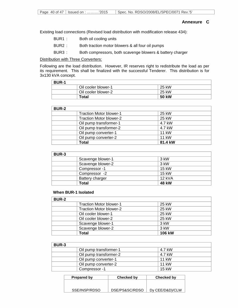
Page 40 of 47 Issued on : ……….’2015 Spec. No. RDSO/2008/EL/SPEC/0071 Rev.’5’
Prepared by Checked by Checked by
SSE/INSP/RDSO DSE/PS&SC/RDSO Dy CEE/D&D)/CLW
Annexure C
Existing load connections (Revised load distribution with modification release 434):
BUR1 : Both oil cooling units
BUR2 : Both traction motor blowers & all four oil pumps
BUR3 : Both compressors, both scavenge blowers & battery charger
Distribution with Three Converters:
Following are the load distribution. However, IR reserves right to redistribute the load as perits requirement. This shall be finalized with the successful Tenderer. This distribution is for3x130 kVA concept.
BUR-1Oil cooler blower-1 25 kWOil cooler blower-2 25 kWTotal 50 kW
BUR-2Traction Motor blower-1 25 kWTraction Motor blower-2 25 kWOil pump transformer-1 4.7 kWOil pump transformer-2 4.7 kWOil pump converter-1 11 kWOil pump converter-2 11 kWTotal 81.4 kW
BUR-3Scavenge blower-1 3 kWScavenge blower-2 3 kWCompressor -1 15 kWCompressor -2 15 kWBattery charger 12 kVATotal 48 kW
When BUR-1 IsolatedBUR-2
Traction Motor blower-1 25 kWTraction Motor blower-2 25 kWOil cooler blower-1 25 kWOil cooler blower-2 25 kWScavenge blower-1 3 kWScavenge blower-2 3 kWTotal 106 kW
BUR-3Oil pump transformer-1 4.7 kWOil pump transformer-2 4.7 kWOil pump converter-1 11 kWOil pump converter-2 11 kWCompressor -1 15 kW

Page 41 of 47 Issued on : ……….’2015 Spec. No. RDSO/2008/EL/SPEC/0071 Rev.’5’
Prepared by Checked by Checked by
SSE/INSP/RDSO DSE/PS&SC/RDSO Dy CEE/D&D)/CLW
Compressor -2 15 kWBattery charger 12 kVATotal 73.4 kW
When BUR-2 ISOLATED
BUR-1Traction Motor blower-1 25 kWTraction Motor blower-2 25 kWOil cooler blower-1 25 kWOil cooler blower-2 25 kWScavenge blower-1 3 kWScavenge blower-2 3 kWTotal 106 kW
BUR-3Oil pump transformer-1 4.7 kWOil pump transformer-2 4.7 kWOil pump converter-1 11 kWOil pump converter-2 11 kWCompressor -1 15 kWCompressor -2 15 kWBattery charger 12 kVATotal 73.4 kW
When BUR-3 ISOLATED
BUR-1Traction Motor blower-1 25 kWTraction Motor blower-2 25 kWOil cooler blower-1 25 kWOil cooler blower-2 25 kWScavenge blower-1 3 kWScavenge blower-2 3 kWTotal 106 kW
BUR-2Oil pump transformer-1 4.7 kWOil pump transformer-2 4.7 kWOil pump converter-1 11 kWOil pump converter-2 11 kWCompressor -1 15 kWCompressor -2 15 kWBattery charger 12 kVATotal 73.4 kW
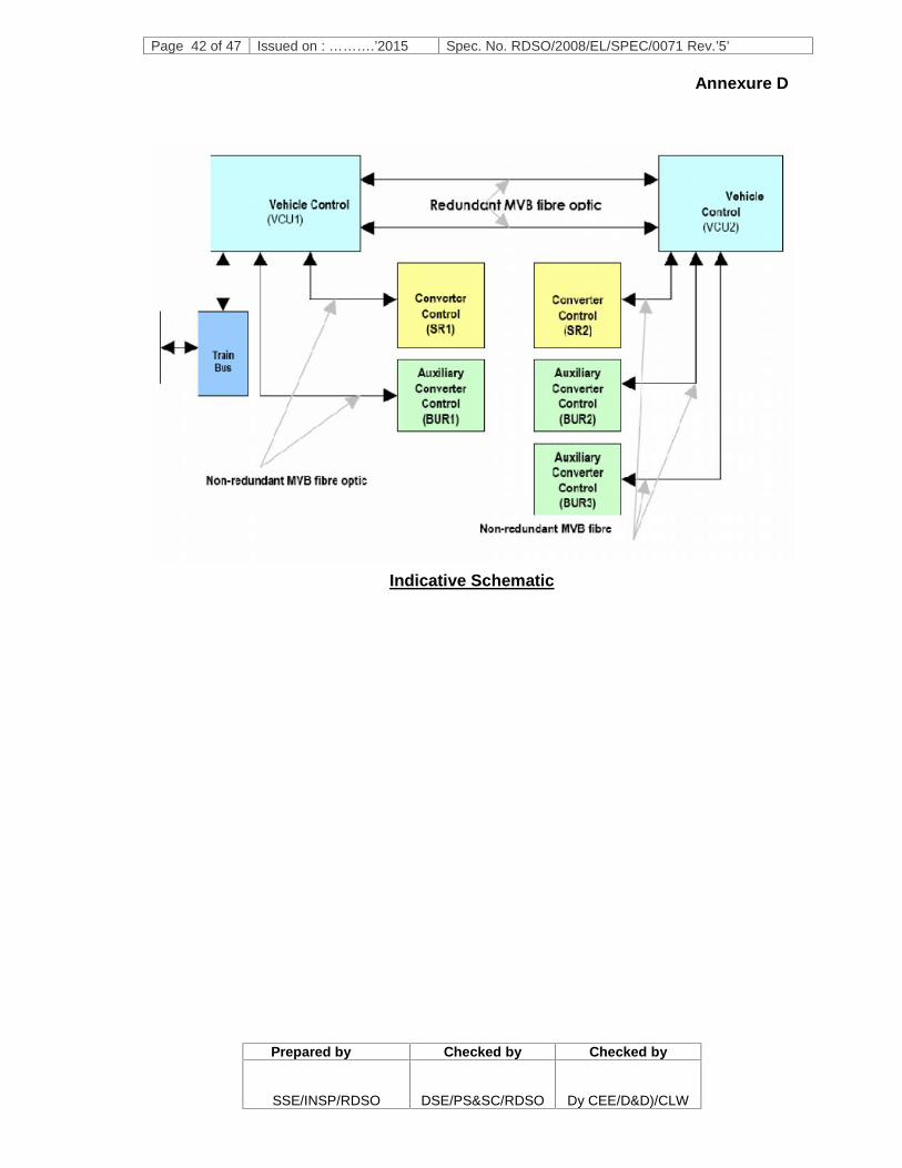
Page 42 of 47 Issued on : ……….’2015 Spec. No. RDSO/2008/EL/SPEC/0071 Rev.’5’
Prepared by Checked by Checked by
SSE/INSP/RDSO DSE/PS&SC/RDSO Dy CEE/D&D)/CLW
Annexure D
Indicative Schematic

Page 43 of 47 Issued on : ……….’2015 Spec. No. RDSO/2008/EL/SPEC/0071 Rev.’5’
Prepared by Checked by Checked by
SSE/INSP/RDSO DSE/PS&SC/RDSO Dy CEE/D&D)/CLW
Annexure E

Page 44 of 47 Issued on : ……….’2015 Spec. No. RDSO/2008/EL/SPEC/0071 Rev.’5’
Prepared by Checked by Checked by
SSE/INSP/RDSO DSE/PS&SC/RDSO Dy CEE/D&D)/CLW
Annexure F1. Modes of Operation (Normal and Degraded)1.1 Unless stated otherwise in this specification the locomotive provided with IGBT
based propulsion equipments in accordance with this specification, shall operate (innormal and degraded conditions) in the same manner as the existingWAG9/WAG9H/WAP7 locomotive as described in the current operational manual(Document number 3EHW411172).
1.2 The Supplier shall investigate the operation and functionality of the existingWAG9/WAG9H/WAP7 locomotive and develop the full functionality of the propulsionequipments to provide a similar level of operation.
1.3 For the avoidance of doubt, in addition to meeting the requirements of thisspecification, it shall be possible for the locomotives, provided with IGBT basedpropulsion equipments in accordance with this specification, to operate as a singlelocomotive in the following modes:
(a) Inching Mode - the WAG9 locomotive shall be able to operate at a constantspeed settable by the driver in steps of 0.1 Km/h, in the range from 0.5 to 1.5Km/h with loads up to 5200 tonnes on a gradient of 1 in 1000 or flatter.. Itshall be possible to change from inching mode to normal mode and vice versaby the driver depending upon his requirement;
(b) Constant Speed Control (CSC) - the locomotive shall be able to operate at apre-set speed selected by the driver. The selection of speed shall be possibleby pressing a switch. However, the system shall be inherently fail safe andshall immediately come out of the pre-set speed mode to normal mode onactuation of the master/ brake controller, reduction of brake pipe pressure,activation of the direct brake or as required from safety considerations;
(c) Shunting Mode – the locomotive shall be able to shunt the wagons/coaches tocreate the train formation. This operation shall be the same as that which isundertaken by the existing WAG9/WAG9H/WAP7 locomotive.
1.4 It shall be possible to operate a locomotive in multiple with other locomotives of thesame type i.e. it shall be possible to operate a Locomotive with other Locomotives.It shall be possible to operate a maximum of 2 (two) locomotives in multipleoperation.
1.5 When operating in multiple the controls of the coupled locomotives shall be achievedfrom the active cab of the leading locomotive. Provision shall also be made to enablethe driver in the active cab to monitor the important parameters of the otherlocomotives as well as to identify important faults in all locomotives.
1.6 Provision shall be made in the control circuitry of the Locomotive, to limit the startingtractive effort to predefined values when required during multiple operations withother locomotives. The two predefined value settings shall be 300 kN and 353 kNper locomotive.
1.7 It shall be possible for the locomotives to operate with other Locomotives in thefollowing modes:
a) trailing mode – the locomotive shall be able to operate the trailinglocomotive’s traction power from the leading Locomotive’s cab, in the eventof total failure of the traction power on the lead locomotive;
b) banking mode – the locomotive is mechanically and pneumatically coupledto the rear of a train and the lead locomotive shall control all the train
Page 45 of 47 Issued on : ……….’2015 Spec. No. RDSO/2008/EL/SPEC/0071 Rev.’5’
Prepared by Checked by Checked by
SSE/INSP/RDSO DSE/PS&SC/RDSO Dy CEE/D&D)/CLW
brakes; although in emergencies the rear locomotive driver can activate theemergency brake; and
c) towing mode – following a failure of a locomotive which is prevented fromoperating under its own power, it shall be possible to haul a Locomotive aspart of a train configuration.
2. Functionality of the Locomotive2.1 Unless stated otherwise in this specification the functionality of the locomotives,
provided with IGBT based propulsion equipments in accordance with thisspecification, shall provide the same operational functionality in normal anddegraded conditions, driver controls and interfaces as the existingWAG9/WAG9H/WAP7 locomotive as described in the current operational manual(Document number 3EHW411172).
2.2 The following clauses provide an overview of the required functionality of thelocomotive. The Supplier shall investigate the operation and functionality of theexisting WAG9/WAG9H/WAP7 locomotive and develop the full functionality of thepropulsion equipments to provide the same level of operation.
2.3 Driving controls and interlocks – the driving controls shall mimic those of the existingWAG9/Wag9H/WAP7 locomotive. The system shall have interlocks to preventtractive effort if the:
a) emergency stop button is active;
b) parking brake remains applied for speed more than 5 km/h;
c) pneumatic (direct) locomotive brake is applied for speed more than 10 km/h;
d) automatic brake is applied for speed more than 10 km/h;
e) main reservoir is below 5.6 Kg/cm2;
f) brake pipe pressure is below 4.7 kg/cm2;
g) isolation cock brake pipe control system is isolated;
h) fire detection system activated; or the
i) emergency exhaust isolating cock is open.
2.4 Traction interlocks – the activation of the traction interlock shall reduce thetractive/braking effort to zero and stop the pulsing of the traction converter. Anindicator shall alert the driver to the loss of tractive/braking effort. The following shallactivate a traction interlock:
a) vigilance system activation;
b) emergency stop button activation;
c) pressure switch emergency brake;
d) battery voltage too low;
e) 110% over speed;
f) failure of electronic brake control;
g) electric brake failure; and
h) any traction converter failure modes, including angle transmitter disturbanceand protective actions where the design process undertaken by the Supplieridentifies that a traction interlock is necessary.

Page 46 of 47 Issued on : ……….’2015 Spec. No. RDSO/2008/EL/SPEC/0071 Rev.’5’
Prepared by Checked by Checked by
SSE/INSP/RDSO DSE/PS&SC/RDSO Dy CEE/D&D)/CLW
2.5 The traction interlock shall be released as soon as the reason for the tractioninterlock disappears and the driver moves the master controller to the neutralposition. This interlock shall be manually released and shall never be an automaticoperation.
2.6 Sanding control – this shall be by automatic and manual operation. The manualoperation shall be by a foot switch. The automatic operation shall be controlled bythe wheel slip/slide control system. Only the leading axles of each bogie shall deliversand to the wheel rail interface dependent on direction of travel. The sand dischargerate shall optimise adhesion whilst not impeding detection through the track circuits.
2.7 Vigilance – the vigilance system requires the driver to operate, as a minimum, eithervigilance foot pedal, the sanding foot pedal, the master controller or the push buttonprovided on the assistant driver’s side, within a 60 second period. Any of theseactions shall reset the timer. Failure to reset the timer within the 60 second periodshall trigger an alarm. The alarm is to be cancelled by the vigilance foot pedal within16±4 seconds. Failure to cancel the alarm shall activate the emergency brake whichshall only be resettable after 32±2 seconds.
2.8 Pantograph control – a mechanical interlock system to ensure that a pantographcannot be raised until all the HV systems are secured and un-earthed shall beinstalled. The Locomotive pantograph shall be raised by a selection switch whichhas three modes and a raise and lower switch which are described below:
a) position "Auto" - automatically selects the pantograph at the opposite end ofthe locomotive to the activated cab;
b) position "I" - selects the pantograph at the cab 1 end to be raised irrespectiveof which cab is active; and
c) position "II" - selects the pantograph at the cab 2 end to be raised irrespectiveof which cab is active.
The selected pantograph shall be raised by the use of an "up" switch. If there isinsufficient air pressure to raise the pantograph an auxiliary pantograph compressorshall be automatically activated. The pantograph shall not raise until the auxiliarycompressor has de-activated;
The pantograph shall be lowered by the use of a "down" switch. The switch shallopen the VCB first, if closed, when activated.
2.9 Compressor Control – the compressors shall be operated in three different modeswhich are described below:
a) operating mode "Off" - with the switch active in this position both compressorsshall be inactive.
b) operating mode "Auto" - with the switch active in this position the compressorsshall supply the pneumatic system automatically cutting out once the pressurereaches 10 kg/cm2. The compressor shall automatically reactivate if the mainreservoir pressure reduces below 8 kg/cm2. The compressors shall operatealternately to ensure that the duty is balanced for both compressors.
c) operating mode "Man" - with the switch active in this position both compressorsshall be active as long as the main circuit breaker is closed. It should be notedthat the compressor cut-out switch shall not operate in this position.

Page 47 of 47 Issued on : ……….’2015 Spec. No. RDSO/2008/EL/SPEC/0071 Rev.’5’
Prepared by Checked by Checked by
SSE/INSP/RDSO DSE/PS&SC/RDSO Dy CEE/D&D)/CLW
2.10 Emergency stop button – there shall be an emergency stop button located on thedriver’s desk that shall open the VCB, lower the pantograph and apply theemergency brake. The system shall be designed such that the control system shallnot reset until the locomotive has come to rest. The button shall be sited such that itis within the reach of the driver but shall not be susceptible to accidental orinadvertent operation.
2.11 Emergency Brake Activation – the emergency brake shall be activated by thefollowing:
a) vigilance equipment exceeding time limits;
b) emergency stop button activation;
c) 110% of maximum speed being exceeded;
d) moving the automatic brake controller to the EMERGENCY position;
e) activation of the emergency brake cock on the assistant driver’s side; and
f) failure of the electronic brake control.
2.12 Parking brake control – the parking brake shall be applied and released by the useof a single latch illuminated pushbutton. The parking brake shall be interlocked withthe traction equipment to prevent the driver taking traction with the parking brakeapplied. The drive shall not be able to apply the parking brake if the Locomotivespeed is greater than 5 Km/h.
2.13 Control of lighting - the control of the Locomotive lighting shall be similar to that ofthe existing WAG9/Wag9H/WAP7 locomotive. The cab lighting shall be controlled bythe driver and all the gauges and meters shall be self illuminated. The machine roomlighting shall be such that all initial fault finding can be undertaken without additionallighting.
2.14 Head lights – the head lights shall have twin beams that are controlled by the driver.
2.15 Marker lights – there shall be two sets of marker lights, one white and one red thatare controlled by the driver.
2.16 Flasher light – in the event of the train parting the flasher light shall be automaticallyactivated and any tractive effort on the locomotive shall be disabled untilacknowledged by the driver. Similarly, in the event of alarm chain pulling the flasherlight shall be automatically activated until acknowledged by the driver. The flasherlight shall have the ability to be activated manually by the driver by operating aswitch provided on the flasher light unit.
****************