Embed Size (px)
Citation preview
i
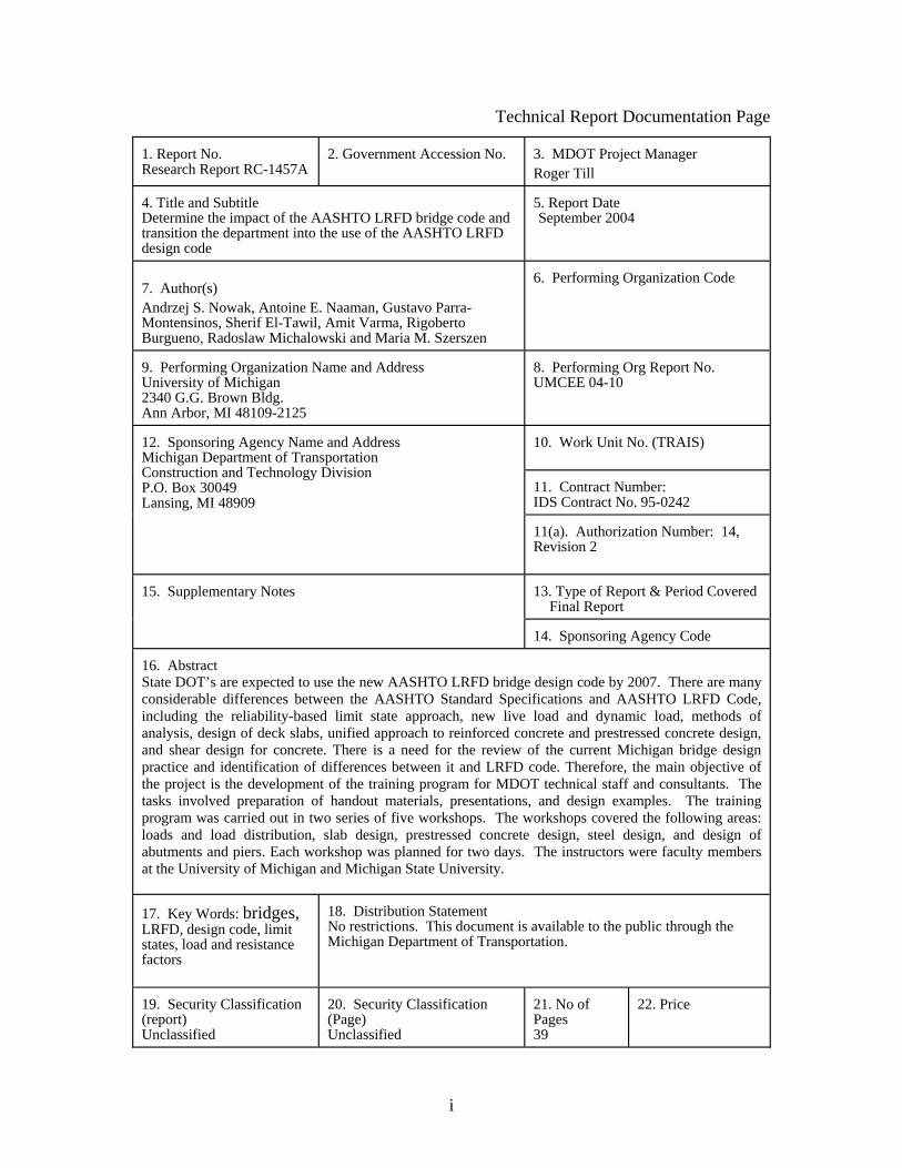
Technical Report Documentation Page 1. Report No. Research Report RC-1457A
2. Government Accession No.
3. MDOT Project Manager Roger Till
4. Title and Subtitle Determine the impact of the AASHTO LRFD bridge code and transition the department into the use of the AASHTO LRFD design code
5. Report Date September 2004
7. Author(s) Andrzej S. Nowak, Antoine E. Naaman, Gustavo Parra-Montensinos, Sherif El-Tawil, Amit Varma, Rigoberto Burgueno, Radoslaw Michalowski and Maria M. Szerszen
6. Performing Organization Code
9. Performing Organization Name and Address University of Michigan 2340 G.G. Brown Bldg. Ann Arbor, MI 48109-2125
8. Performing Org Report No. UMCEE 04-10
10. Work Unit No. (TRAIS) 11. Contract Number: IDS Contract No. 95-0242
12. Sponsoring Agency Name and Address Michigan Department of Transportation Construction and Technology Division P.O. Box 30049 Lansing, MI 48909
11(a). Authorization Number: 14, Revision 2 13. Type of Report & Period Covered Final Report
15. Supplementary Notes
14. Sponsoring Agency Code
16. Abstract State DOT’s are expected to use the new AASHTO LRFD bridge design code by 2007. There are many considerable differences between the AASHTO Standard Specifications and AASHTO LRFD Code, including the reliability-based limit state approach, new live load and dynamic load, methods of analysis, design of deck slabs, unified approach to reinforced concrete and prestressed concrete design, and shear design for concrete. There is a need for the review of the current Michigan bridge design practice and identification of differences between it and LRFD code. Therefore, the main objective of the project is the development of the training program for MDOT technical staff and consultants. The tasks involved preparation of handout materials, presentations, and design examples. The training program was carried out in two series of five workshops. The workshops covered the following areas: loads and load distribution, slab design, prestressed concrete design, steel design, and design of abutments and piers. Each workshop was planned for two days. The instructors were faculty members at the University of Michigan and Michigan State University. 17. Key Words: bridges, LRFD, design code, limit states, load and resistance factors
18. Distribution Statement No restrictions. This document is available to the public through the Michigan Department of Transportation.
19. Security Classification (report) Unclassified
20. Security Classification (Page) Unclassified
21. No of Pages 39
22. Price
ii
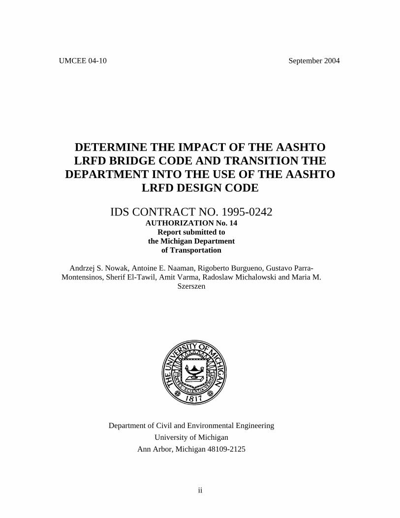
UMCEE 04-10 September 2004
DETERMINE THE IMPACT OF THE AASHTO LRFD BRIDGE CODE AND TRANSITION THE
DEPARTMENT INTO THE USE OF THE AASHTO LRFD DESIGN CODE
IDS CONTRACT NO. 1995-0242
AUTHORIZATION No. 14 Report submitted to
the Michigan Department of Transportation
Andrzej S. Nowak, Antoine E. Naaman, Rigoberto Burgueno, Gustavo Parra-
Montensinos, Sherif El-Tawil, Amit Varma, Radoslaw Michalowski and Maria M. Szerszen
Department of Civil and Environmental Engineering University of Michigan
Ann Arbor, Michigan 48109-2125

iii
DISCLAIMER
The contents of this report reflect the views of the authors, who are responsible for the facts and the accuracy of the information presented herein. This document is disseminated under the sponsorship of the Michigan Department of Transportation, in the interest of information exchange. The Michigan Department of Transportation assumes no liability for the contents or use thereof.

iv
Executive Summary
The Report documents the work performed as part of this project. State DOT’s are
expected to use the new AASHTO LRFD bridge design code by 2007. There are many
considerable differences between the AASHTO Standard Specifications and AASHTO
LRFD Code, including the reliability-based limit state approach, new live load and
dynamic load, methods of analysis, design of deck slabs, unified approach to reinforced
concrete and prestressed concrete design, and shear design for concrete. There is a need
for the review of the current Michigan practice and identification of differences between
it and LRFD code.
Therefore, the main objective of the project is the development of the training program
for MDOT technical staff and consultants. The tasks involved preparation of handout
materials, presentations, and design examples. The training program was carried out in
two series of workshops. Each series consisted of five Workshops developed by the team
of instructors at the University of Michigan and Michigan State University:
Workshop 1. Loads and Load distribution
Workshop 2. Reinforced Concrete Slab Design including Bridge Deck Design and Shear
Workshop 3. Prestressed concrete
Workshop 4. Steel Superstructure Design
Workshop 5. Concrete Pier and Abutment Design
Each workshop was planned for two days and it included lecture-style presentations,
presentations of design examples, and discussion.
The current MDOT practice as presented in the Michigan Bridge Design Manual was
reviewed and compared with the new AASHTO LRFD Code. The required changes in
the Michigan Bridge Design Manual to comply with the LRFD code were identified and
marked in the text.

v
TABLE OF CONTENTS
Executive Summary………………….........................................................................iv Acknowledgments.......................................................................................................vii
1. Introduction…………………………………...……...…............................................. 1 2. Objectives and Scope of the Project………………...…….......................................... 3
3. Workshop Program and Time Schedule…………………..….......................…......... 5
4. Workshop 1, Load and Load Distribution ………………………………………....... 7
5. Workshop 2, Reinforced Concrete Slab Design including Shear………………........11
6. Workshop 3, Prestressed Concrete ……………………………..........…...........…... 13
7. Workshop 4, Steel Superstructure Design……………...........…............................... 17
8. Workshop 5, Concrete Pier and Abutment Design ………………….....….............. 21
9. Instructors……………………….......................…........……........…........................ 23 10. Evaluation by Participants………….....................................................…............... 27
Appendix A Handouts……………….................................................……....................31
Appendix B Recommended Changes in the Michigan Design Manual………..............33

vi
Acknowledgments
The Workshops are sponsored by the Michigan Department of Transportation (MDOT)
which is gratefully acknowledged. Thanks are due to the technical staff of the Michigan
DOT, Roger Till, Sudhakar Kulkarni, David Juntunen, Steven Beck, Ali Mahdavi, John
Lazar, Phil Grotenhuis, Terry Frake and other members of Technical Advisory Group for
their useful comments, discussions and support.
The background material was prepared by the instructors assisted by students and staff of
the University of Michigan and Michigan State University. In particular, thanks are due
to Dr. Junsik Eom, David Ferrand, Taejun Cho, Aurelie Gregoire, Marco Breccolotti,
Pascal Laumet, Piotr Podhorecki and Artur Czarnecki. They were involved in
preparation of examples and parts of the text.
The realization of the project would not be possible without in kind support of the
Michigan DOT, University of Michigan and Michigan State University, including
reports, design guides, computer facilities, and library.

1
1. INTRODUCTION
The new LRFD AASHTO code was developed in 1994, and the 2nd edition was published
in 1998. AASHTO Subcommittee on Bridges and Structures decided to discontinue the
maintenance of the Standard Specifications and phase it out within the next few years.
The LRFD design code is the state-of-the-art document including provisions that are very
different from the Standard Specifications. The major changes include:
• Design is based on limit state philosophy and reliability analysis.
• Four types of limit states are considered, with load and resistance factors specified
for each limit state and material.
• Introduction of structural analysis methods.
• Live load and dynamic load.
• Live load distribution factors.
• Reinforced concrete and prestressed concrete design are integrated.
• Shear design of reinforced concrete and prestressed concrete.
• Expanded coverage of hydraulics and scour.
In addition, a considerable effort has been focused on the maintenance of the LRFD code
(NCHRP 12-42), as well as the development of LRFD-based additional chapters of the
code and design guides, dealing with specialized topics including steel curved girder
bridges (NCHRP 12-52), segmental bridges, seismic design of bridges (NCHRP 12-49),
design of retaining walls and substructure (NCHRP 12-55), design for extreme events
(NCHRP 12-48), moveable bridges (NCHRP 12-44). An application of these new
documents requires additional effort by the designers.
Therefore, there is a need for assisting the Michigan DOT in transition from the Standard
Specification to LRFD code. The need includes evaluation of the impact of the new code
provisions on Michigan bridge design practice, in particular,
• comparison with the current practice,

2
• for various structural types used in Michigan, checking if the new code is more or
less conservative,
• identification of clauses which require clarification
• identification of the need for changes in current practice
• identification of the need for new software and other support systems
Then, there is a need for the development and implementation of training program for the
Michigan DOT technical staff.

3
2. OBJECTIVES AND SCOPE OF THE PROJECT
The main objectives of the project are:
• identification of the needs for implementation of the LRFD AASHTO Code into
Michigan bridge design practice,
• development of the training program, including design examples and workshops
• organization and implementation of training sessions (workshops)
The project is within the MDOT Research Program Strategic Direction, under two goals:
• Improve Design, Construction and Maintenance Methods, measurable outcomes 3
(better understanding of the design code), 5 (better performance of the structure
designed using more rational code), 9 (design structures will be more cost
efficient), and 10 (the LRFD Code is based on the state-of-the-art research
findings).
• Provide Training, Education, and Process Improvement, measurable outcomes 1,
2, 3, 5, 9 and 10.
A series of five Workshops has been developed by the team of instructors at the
University of Michigan and Michigan State University:
Workshop 1. Loads and Load Distribution
Workshop 2. Reinforced Concrete Slab Design including Bridge Deck Design and Shear
Workshop 3. Prestressed Concrete
Workshop 4. Steel Superstructure Design
Workshop 5. Concrete Pier and Abutment Design

4
Note:
Intentionally left blank

5
3. WORKSHOP PROGRAM AND TIME SCHEDULE The Workshops were organized in two series, and each Workshop included a two day
program. The program included morning sessions (8-12), lunch break, and afternoon
sessions (1-4), with coffee breaks approximately every hour.
Series 1
Workshop 1, March 10-11, 2003
Workshop 2, April 3-4, 2003
Workshop 3, April 17-18, 2003
Workshop 4, May 1-2, 2003
Workshop 5, May 14-15, 2003
Series 2
Workshop 1, September 25-26, 2003
Workshop 2, October 2-3, 2003
Workshop 3, October 22-23, 2003
Workshop 4, November 6-7, 2003
Workshop 5, November 19-20, 2003
The material was presented using LCD computer projectors and PowerPoint slides and
MS Word files. The sessions included lecture-style presentations, design examples, and
discussion.

6
Note:
Intentionally left blank

7
4. WORKSHOP 1 - LOAD AND LOAD DITRIBUTION
Instructors: Andrzej S. Nowak and Rigoberto Burgueno.
The topics covered in the Workshop include:
Part A: 1.1 LRFD Philosophy
1.1.1 General Structure of the Code, Sections, Commentary 1.1.2 Loads, load combinations, and load application 1.1.3 Limit states 1.1 4 Strength limit state 1.1.5 Service limit state 1.1.6 Fatigue and fracture limit state 1.1.7 Extreme event limit state
1.2. Load Combinations and Load Factors 1.2.1 Load factors for construction loads, 1.3 Permanent Loads
1.3.1 Dead loads: DC, DW and EV
1.4 Live Loads: LL and PL
1.4.1 Number of Design Lanes 1.4.2 Multiple presence of live load 1.4.3 Design Vehicular Live Load 1.4.4 Design Truck 1.4.5 Design Tandem 1.4.6 Design lane load 1.4.7 Tire contact area 1.4.8 Distribution of Wheel loads through earth fills 1.4.9 Application of design vehicular live load 1.4.10 Pedestrian loads 1.4.11 Deck overhang design 1.4.12 Fatigue load 1.4.13 Load distribution for fatigue
1.5 Dynamic Load Allowance 1.6 Centrifugal Force

8
1.7 Braking Force 1.8 Vehicular Collision Force 1.9 Water Loads
1.9.1 Static Pressure 1.9.2 Buoyancy 1.9.3 Stream Pressure 1.9.4 Wave Load 1.9.5 Change in foundations due to limit state for scour
1.10 Wind Load: WL and WS
1.10.1 Horizontal Wind Pressure 1.10.2 Wind pressure on structures 1.10.3 Wind pressure on vehicles 1.10.4 Vertical wind pressure 1.10.5 Aeroelastic instability 1.11 Ice Loads: IC 1.11.1 Dynamic ice forces on piers
Part B: 1.1 STRUCTURAL ANALYSIS AND EVALUATION METHODS
1.1.1 Introduction and Scope 1.1.1.1 Convention and Notation 1.1.2 Modeling and Analysis 1.1.3 Fundamentals of Bridge Superstructure Behavior 1.1.4 Methods of Analysis 1.1.5 Analysis of Slab Decks 1.1.6 Analysis of Beam-and-Slab Decks 1.1.7 Analysis of Cellular Decks 1.1.7 The AASHTO Method of Analysis
1.2 APPROXIMATE METHODS OF ANALYSIS
1.2.1 General 1.2.2 Load Distribution Concept 1.2.3 Decks 1.2.4 Lever Rule Method

9
1.2.5 Beam-Slab Bridges 1.2.6 Cellular Bridges 1.2.7 Effective Flange Width 1.2.8 Skew Decks
1.3 REFINED METHODS OF ANALYSIS 1.3.1 General 1.3.2 Grillage Analysis of Slab Decks 1.3.3 Grillage Analysis of Beam-Slab Bridges 1.3.4 Grillage Analysis of Cellular and Box Bridges 1.3.5 Grillage Meshes for Skew Decks
1.4 Finite Element Method
1.4.1 General 1.4.2 Structural Members 1.4.3 Meshing Considerations 1.4.4 Boundary Conditions and Member Connections
1.5 ANALYSIS FOR TEMPERATURE GRADIENT
1.5.1 Temperature Effects 1 1.5.2 Principal Stresses 1.5.3 Secondary Stresses 1.5.4 Total Stresses 1.5.5 Other Considerations 1.5.6 Discrete Form of Temperature Induced Deformation Relations 1.5.7 Example 14 - Nonlinear Thermal Stresses 1.5.8 Example 15 - Secondary Stresses 1.5.9 Summary of Temperature Stress Analysis Procedure

10
Note:
Intentionally left blank

11
5. WORKSHOP 2 – REINFORCED CONCRETE SLAB DESIGN AND SHEAR
Instructors: Andrzej S. Nowak and Gustavo Parra-Montesinos.
The topics covered in the Workshop include:
1. Introduction
1.1. AASHTO LRFD Code - Organization of the Code, Sections covering concrete deck slabs design 1.2. Types of Decks covered by Analysis 1.3. Materials
1.3.1. Concrete 1.3.2. Reinforcing Steel 1.3.3. Prestressing Steel
2. Design - Limit States
2.1. Strength Limit State (A.9.5.4)
3. Design – Loads
3.1. Dead Loads (A.3.5) 3.1. Live Loads
3.1.1. Vehicular Live Load 3.1.2. Fatigue Load 3.1.3. Application of the Vehicular Load
4. Design - Criteria for Deflection (A.2.5.2.6.2) 5. Design - Methods of Analysis
5.1. Strip Method (A.4.6.2 - Approximate Methods of Analysis for Concrete Decks) 5.2. Empirical Method (A.9.7.2)
6. Design – Overhangs 7. Design- Slab Superstructures 8. Design - Stay-in-Place Formwork Decks 9. Joints in precast decks 10. Shear design 11. Example of shear design

12
Note:
Intentionally left blank

13
6. WORKSHOP 3 – PRESTRESSED CONCRETE DESIGN
Instructors: Antoine E. Naaman, Gustavo Parra-Montesinos and Andrzej S. Nowak.
The topics covered in the Workshop include:
1. Introduction: prestressing materials and systems; terminology; sign convention. 2. Bending in non-composite beams: working stress analysis and design;
Overall design process; stress inequality conditions; geometric representation of Service I and Service III limit states; prestressing force and eccentricity.
Example 1-a: Single T-beam 3. Bending: ultimate strength analysis and design
equilibrium equations; criteria for minimum and maximum reinforcements; stress in prestressing steel at ultimate; R versus T sections; Example 1-b: Single T-beam (continued)
4. Design for Shear:
background to AASHTO LRFD; compression field theory and strut-and-tie modeling. Example 1-c: Single T-beam (continued) 5. Deflection computation and control. deflections types: short and long term; theorems and formulae for deflections; cracked
sections; deflection limitation and control Example 1-d: Single T-beam (continued)
6. Analysis and Design of Composite Beams
particular design aspects; loading stages, shored vs. unshored; transformed section; horizontal shear transfer; tie reinforcement design; stress inequality conditions for composite beams; geometric representation; prestressing force design; nominal bending resistance.
Example 2-a: AASHTO No. IV precast beam with cast-in-place RC slab as part of a four lane bridge deck.
7. Design of RC slab at supports made continuous for live loads Example 2-b: AASHTO No. IV precast beam with cast-in-place RC slab made
continuous over two spans. 8. Example: Adjacent precast prestressed box beams for a two-lanes bridge deck 9. Prestress Losses
source of losses; type of losses in pretensioned and post-tensioned members; lump sum estimate of total losses according to AASHTO; lump sum estimates of separate losses.

14
10. Special Topics Introduction to partial prestressing, external prestressing, how to determine stresses with unbonded tendons.
11. Closing remarks. Note: The course notes include 2 main parts:
• Part 1: Background Information and Theory • Part 2: Examples
While the examples of Part 2 are self explanatory to the informed user, basic derivations and fundamentals can be found in the material of Part 1. Additional information on the teaching strategy is explained below. Part 1: Background Information and Theory Part 1 comprises several portions of chapters taken from the following textbook: “Prestressed Concrete Analysis and Design: Fundamentals, ©” by A.E. Naaman, 2nd Edition, in progress, 2003; these are directly related to the material treated in the examples. They are: Chapter 1: Introduction Chapter 2: Prestressing Materials Chapter 4: Flexure: Working Stress Analysis and Design Chapter 5: Flexure: Ultimate Strength Analysis and Design Design for Shear – Summary: prepared by G. Parra Montesinos Chapter 7: Deflection Computation and Control Chapter 8: Prestress Losses Chapter 9: Analysis and Design of Composite Beams Chapter 14: Prestressed Concrete Bridges Page numbers refer first to the chapter number, then to the page within that chapter, such as: 4.11, that is, page 11 of chapter 4. This allows the user to eventually go back to the book, find the reference material, and expand the reading if needed. A similar notation is given for section numbers, equation numbers, figure numbers, table numbers and reference numbers. Because an attempt is made to limit the material presented, intermediate sections in a given portion of chapter, may have been omitted. Part 2: Examples Part 2 comprises four design examples taken from the same textbook mentioned in Part 1, but adapted for continuity for the purpose of these notes. Two of the examples are complete and cover design for bending for service and strength limit states, design for shear (vertical and horizontal if relevant), detailing the prestressing steel profile, checking for deflections, and computation of prestress losses. The four examples are: Example 1: Non-Composite Prestressed T-Beam for a Foot Bridge
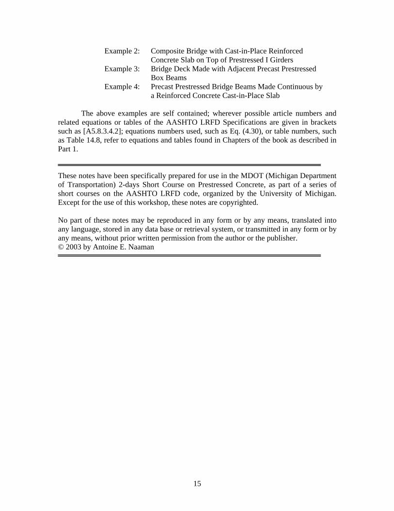
15
Example 2: Composite Bridge with Cast-in-Place Reinforced Concrete Slab on Top of Prestressed I Girders Example 3: Bridge Deck Made with Adjacent Precast Prestressed Box Beams Example 4: Precast Prestressed Bridge Beams Made Continuous by a Reinforced Concrete Cast-in-Place Slab The above examples are self contained; wherever possible article numbers and related equations or tables of the AASHTO LRFD Specifications are given in brackets such as [A5.8.3.4.2]; equations numbers used, such as Eq. (4.30), or table numbers, such as Table 14.8, refer to equations and tables found in Chapters of the book as described in Part 1. These notes have been specifically prepared for use in the MDOT (Michigan Department of Transportation) 2-days Short Course on Prestressed Concrete, as part of a series of short courses on the AASHTO LRFD code, organized by the University of Michigan. Except for the use of this workshop, these notes are copyrighted. No part of these notes may be reproduced in any form or by any means, translated into any language, stored in any data base or retrieval system, or transmitted in any form or by any means, without prior written permission from the author or the publisher. © 2003 by Antoine E. Naaman

16
Note:
Intentionally left blank

17
7. WORKSHOP 4 – STEEL SUPERSTRUCTURE DESIGN
Instructors: Sherif El-Tawil, Amit Varma and Andrzej S. Nowak.
The topics covered in the Workshop include:
1. Introduction
1.1. AASHTO LRFD Code Sections Pertaining to Steel Design Discuss structure of Section 6 in the code. Highlight major differences between LRFD and ASD.
1.2. Types of Components.
Tension members, compression members, composite action, flexural members (I-members and box girders), stiffeners, bolted connections, welded connections, diaphragms, bracing members.
1.3. Materials
Overview of steelmaking process. Production of finished products. Classification of 1) structural steels, 2) pins, rollers, and rockers, 3) bolts, nuts and washers, 4) stud shear connectors, and 5) weld metals. Residual stresses and the role they play in structural behavior. Fatigue. Ductile fracture. Brittle facture. Charpy v-notch test.
1.4. Corrosion Control
Techniques for corrosion control. 1.5. General Design Requirements
Effective span length. Dead load camber. Minimum thickness of steel. Diaphragms and cross-frames. Lateral bracing.
2. Limit States
2.1. General Introduction Review basic LRFD methodology.
2.2. Service Limit State Review service limit state equations.
2.3. Fatigue and Fracture Limit State
Review fatigue limit state equations. Discuss bolts and member fracture toughness requirements.
2.4. Strength Limit States
Discuss resistance factors and review strength limit state equations.

18
3. Tension and Compression Members
3.1. Tension Members Tensile failure mechanisms. Tensile resistance. Reduction factor. Net area. Limiting slenderness ratio. Combined tension and flexure.
3.2. Compression Members
Global buckling and local buckling issues. Inelastic buckling. Compression resistance. Combined axial compression and flexure. Limiting slenderness ratio.
4. Composite I-Girders in Flexure
4.1. General Considerations Flexural failure mechanisms. Section proportion limits.
4.2. Composite Action
Definition of composite action. Degree of composite action. Effective slab width. Basic section properties. Positive and negative flexure. Yield moment. Plastic Moment. Stiffness. Constructability issues.
4.3. Wind Effects
Compact and noncompact sections. 4.4. Flexural Strength Limit State
Review of resistance factors. Cross-section classification. Effect of flange and web slenderness on strength. Definition of flexural resistance. Ductility requirements. Lateral torsional buckling. Moment gradient effect.
4.5. Service Limit State Deflection control. Moment redistribution.
4.6. Fatigue Limit State
Flexure and shear considerations.
4.7. Shear Strength Limit State Review of resistance factors. Review of inelastic shear resistance and tension field theory. Resistance of stiffened and unstiffened webs. Resistance of shear connectors. Pitch, transverse spacing, cover, and fatigue resistance of shear connectors.
4.8. Stiffeners
Transverse intermediate stiffeners. Bearing stiffeners. 5. Examples

19
6. Box Girders in Flexure
6.1. General Introduction Limitations of provisions. Economic considerations for single versus multiple box girders. Live load distribution in multiple box girders. Torsional effects in boxes. Analysis techniques for box girders. Bearings.
6.2. Flexural Strength Limit State
Review of resistance factors. Positive and negative flexural resistance. Compression flange bracing.
6.3. Shear Strength Limit State Review of resistance factors. Resistance of stiffened and unstiffened webs. Resistance of shear connectors. Pitch, transverse spacing, cover, and fatigue resistance of shear connectors.
6.4. Stiffeners
Web stiffeners. Compression flange stiffeners. 6.5. Constructability
Web and compression flange slenderness. Shear.
7. Example 8. Fatigue and Fracture Considerations
8.1. General Introduction Factors affecting fatigue behavior. Definition of load-induced and distortion induced fatigue. Ductile fracture. Brittle fracture. Factors affecting fracture processes.
8.2. Load-Induced Fatigue Design criteria. Detail categories. Restricted use details. Fatigue resistance.
8.3. Distortion-Induced Fatigue
Transverse connection plates. Lateral connection plates. 8.4. Fracture
Fracture critical members. Temperature zone designations. Charpy v-notch requirements 9. Connections
9.1. General Introduction
9.2. Bolted Connections

20
Slip critical connections. Bearing type connections. Connection resistance for combined loading. Bolts, nuts and washers. Holes. General dimensioning guidelines. Prying action. Bolted splices
9.3. Welded Connections Types of welding. Resistance under combined loading. Block shear. Welded splices.
10. Curved I-Girders
10.1. General Introduction Challenges in designing curved girders including composite interaction between the concrete deck and steel girders, local buckling, torsional warping, distortional warping, interaction between different kinds of cross-sectional forces, and the effect of horizontal bridge curvature on both local and global behavior. Discuss project CURT and the new CSBR. Introduce LRFD design.
10.2. Analysis of Curved Bridges
Accurate methods. Approximate methods. Load distribution. 10.3. Design of Curved Bridges
Effect of curvature on various limit states.
11. Closing remarks

21
8. WORKSHOP 5 – CONCRETE PIER AND ABUTMENT DESIGN
Instructors: Andrzej S. Nowak and Radoslaw Michalowski.
The topics covered in the Workshop include:
1 Introduction
1.1 Definitions 1.2 Substructures in AASHTO LRFD Code 1.3 Abutments, piers and walls (types and dimensions) 1.4 Foundations (foundations under piers, abutments)
2 Loads on piers and abutments
2.1 Horizontal and vertical earth pressure on retaining walls and abutments 2.2 Dead load 2.3 Live load on approach 2.4 Live load on structure 2.5 Contraction 2.6 Expansion (abutment fixed to superstructure)
3 Limit states as defined by AASHTO
3.1 Service limit states 3.2 Bearing resistance and stability
3.2.1 Bearing resistance 3.2.2 Overturning 3.2.3 Overall stability 3.2.4 Passive resistance 3.2.5 Sliding 3.2.6 Structural failure
4 Examples
5 Design of retaining walls
5.1 Concrete cantilever retaining walls 5.2 Concrete bridge abutment 5.3 Modular walls
6 Design of piers 7 Design of abutments

22
8 Design of a footings for piers and abutments 9 Example of pier design 10 Example of abutment design
11 Closing remarks

23
9. INSTRUCTORS
The team of instructors includes:
Dr. Rigoberto Burgueño is an assistant professor of structural engineering at Michigan
State University. Dr. Burgueño's involvement in bridge engineering has been primarily
as a researcher in the implementation of advanced composite materials for civil
infrastructure. His research contributed significantly to the development and construction
of the Kings Stormwater Channel Bridge and the I-5/Gilman Advanced Technology
Bridge in California. He is an associate member of ACI Committee 440 on Fiber
Reinforced Polymer (FRP) Reinforcement.
Sherif El-Tawil, PhD, PE is associate professor of Civil Engineering at the University of
Michigan. His research focuses on steel and composite steel-concrete buildings and
bridges. He is secretary of ASCE's Composite Construction Committee and is a member
of ASCE's Seismic Effects and Analysis Methods Committees and ACI's Composite and
Hybrid Systems Committee. He is associate editor for the ASCE Journal of Structural
Engineering and is recipient of the 2002 Norman Medal from ASCE.
Radoslaw L. Michalowski, Ph.D. (1980) in Civil Engineering, Technical University of
Poznan (Poland), and Institute of Fundamental Technological Research (Polish Academy
of Sciences, Warsaw); M.S. (1974) in Civil Engineering, Technical University of
Poznan (Poland). Present position: Professor of Civil Engineering at The University of
Michigan, Ann Arbor; formerly faculty member at the Johns Hopkins University
(Baltimore) and University of Minnesota. Primary interests: interaction of structures and
foundations, transportation infrastructure, limit state analysis.
Antoine (Tony) E. Naaman is Professor of Civil Engineering in the Department of Civil
and Environmental Engineering at the University of Michigan, Ann Arbor. He obtained
a MS (1970) and Ph.D. (1972) degrees in Civil Engineering from the Massachusetts
Institute of Technology and has been involved in teaching and research since then. His

24
interests include prestressed concrete, high performance fiber reinforced cement
composites, and the integration-tailoring of advanced construction materials to improve
structural performance. He has written two textbooks (one on prestressed concrete), co-
edited eight books, and authored or co-authored more than 250 technical papers. He was
responsible for developing part of the provisions on partial prestressing and prestress
losses for the AASHTO LRFD specifications. He is a Fellow of ACI, ASCE, PCI and
IFS, and active on several of their technical committees.
Andrzej S. Nowak is professor of Civil Engineering at the University of Michigan since
1979. His research led to the development of a probabilistic basis for the new generation
of design codes, including the LRFD AASHTO Code, ACI 318 Code for Concrete
Structures, the Canadian and Ontario Highway Bridge Design Codes, and fatigue
evaluation criteria for BS-5400. Professor Nowak has authored and co-authored over 300
publications. He chairs TRB Committee A2C00 on Structures, ASCE Committee on
Structural Safety and Reliability, ASCE Committee on LRFD, and he is a past chair of
ACI Committee 348 on Structural Safety, and TRB Committee A2C05 on Dynamics and
Field Testing of Bridges. He is a Fellow of ASCE and ACI, and a recipient of the ASCE
Moisseiff Award.
Gustavo Parra is Assistant Professor in the Department of Civil and Environmental
Engineering at the University of Michigan, Ann Arbor. He obtained his B.S. degree in
Civil Engineering at Universidad Metropolitana, Venezuela, in 1994, and his M.S.E. and
Ph.D. degrees in Civil Engineering at the University of Michigan in 1997 and 2000,
respectively. Prof. Parra’s research areas include the behavior and design of reinforced
concrete and hybrid steel-concrete structures subjected to static and dynamic loading. He
has also worked on retrofit of reinforced concrete and hybrid structures, and the use of
fiber reinforced concrete to improve the behavior of reinforced concrete structures. Prof.
Parra is a member of ACI Committee 335, Composite and Hybrid Structures, ACI
Committee 352, Joints and Connections in Monolithic Concrete Structures, and ASCE
Committee on Composite Construction.

25
Amit Varma is an Assistant Professor at Michigan State University. He received his
Ph.D. in civil engineering from Lehigh University. His areas of interest include steel and
steel-concrete composite structures. Currently, he is actively conducting research on
the repair and rehabilitation of damaged steel bridges in Michigan.

26
Note:
Intentionally left blank

27
APPENDIX A – HANDOUTS
The handouts are included on the enclosed CD. For each Workshop there are several
groups of material:
(a) Notes - background material
(b) Slides - PowerPoint presentation
(c) Examples

28
Note:
Intentionally left blank

29
APPENDIX B – RECOMMENDED CHANGES IN THE MICHIGAN DESIGN MANUAL
The recommended changes are marked on the pages of the Michigan Design Manual,
included on the CD.